EP1617001A2 - Heat insulation system for an exterior cavity wall - Google Patents
Heat insulation system for an exterior cavity wall Download PDFInfo
- Publication number
- EP1617001A2 EP1617001A2 EP05015003A EP05015003A EP1617001A2 EP 1617001 A2 EP1617001 A2 EP 1617001A2 EP 05015003 A EP05015003 A EP 05015003A EP 05015003 A EP05015003 A EP 05015003A EP 1617001 A2 EP1617001 A2 EP 1617001A2
- Authority
- EP
- European Patent Office
- Prior art keywords
- insulating
- thermal insulation
- insulation system
- elements
- anchors
- Prior art date
- Legal status (The legal status is an assumption and is not a legal conclusion. Google has not performed a legal analysis and makes no representation as to the accuracy of the status listed.)
- Granted
Links
- 238000009413 insulation Methods 0.000 title claims abstract description 106
- 238000009423 ventilation Methods 0.000 claims abstract description 8
- 239000011491 glass wool Substances 0.000 claims abstract description 6
- 239000011490 mineral wool Substances 0.000 claims description 11
- 239000006260 foam Substances 0.000 claims description 4
- 230000002209 hydrophobic effect Effects 0.000 claims description 3
- 239000011810 insulating material Substances 0.000 claims description 3
- 239000003365 glass fiber Substances 0.000 claims description 2
- 239000006261 foam material Substances 0.000 abstract 1
- 239000010410 layer Substances 0.000 description 14
- 239000004575 stone Substances 0.000 description 9
- 238000010276 construction Methods 0.000 description 6
- 238000009434 installation Methods 0.000 description 4
- 239000002131 composite material Substances 0.000 description 3
- 239000004570 mortar (masonry) Substances 0.000 description 3
- 239000011449 brick Substances 0.000 description 2
- 239000011476 clinker brick Substances 0.000 description 2
- 230000001419 dependent effect Effects 0.000 description 2
- 238000011161 development Methods 0.000 description 2
- 230000018109 developmental process Effects 0.000 description 2
- 239000002356 single layer Substances 0.000 description 2
- 230000006978 adaptation Effects 0.000 description 1
- 239000011230 binding agent Substances 0.000 description 1
- 230000000295 complement effect Effects 0.000 description 1
- 230000000694 effects Effects 0.000 description 1
- 239000011521 glass Substances 0.000 description 1
- 239000012774 insulation material Substances 0.000 description 1
- 238000003475 lamination Methods 0.000 description 1
- 238000004519 manufacturing process Methods 0.000 description 1
- 238000000034 method Methods 0.000 description 1
- 230000035939 shock Effects 0.000 description 1
- 230000003068 static effect Effects 0.000 description 1
- 238000010408 sweeping Methods 0.000 description 1
- XLYOFNOQVPJJNP-UHFFFAOYSA-N water Substances O XLYOFNOQVPJJNP-UHFFFAOYSA-N 0.000 description 1
Images


Classifications
-
- E—FIXED CONSTRUCTIONS
- E04—BUILDING
- E04B—GENERAL BUILDING CONSTRUCTIONS; WALLS, e.g. PARTITIONS; ROOFS; FLOORS; CEILINGS; INSULATION OR OTHER PROTECTION OF BUILDINGS
- E04B1/00—Constructions in general; Structures which are not restricted either to walls, e.g. partitions, or floors or ceilings or roofs
- E04B1/62—Insulation or other protection; Elements or use of specified material therefor
- E04B1/74—Heat, sound or noise insulation, absorption, or reflection; Other building methods affording favourable thermal or acoustical conditions, e.g. accumulating of heat within walls
- E04B1/76—Heat, sound or noise insulation, absorption, or reflection; Other building methods affording favourable thermal or acoustical conditions, e.g. accumulating of heat within walls specifically with respect to heat only
- E04B1/7608—Heat, sound or noise insulation, absorption, or reflection; Other building methods affording favourable thermal or acoustical conditions, e.g. accumulating of heat within walls specifically with respect to heat only comprising a prefabricated insulating layer, disposed between two other layers or panels
- E04B1/7612—Heat, sound or noise insulation, absorption, or reflection; Other building methods affording favourable thermal or acoustical conditions, e.g. accumulating of heat within walls specifically with respect to heat only comprising a prefabricated insulating layer, disposed between two other layers or panels in combination with an air space
- E04B1/7616—Heat, sound or noise insulation, absorption, or reflection; Other building methods affording favourable thermal or acoustical conditions, e.g. accumulating of heat within walls specifically with respect to heat only comprising a prefabricated insulating layer, disposed between two other layers or panels in combination with an air space with insulation-layer locating devices combined with wall ties
Definitions
- the invention relates to a thermal insulation system for clam shell exterior walls, as well as suitable insulation elements.
- Corresponding thermal insulation systems are generally known (cf., DE 35 46 968 C2). These thermal insulation systems are used for clam shell exterior walls with at least one between the shells arranged insulation layer with and without ventilation and for a core insulation in masonry construction.
- wire anchors are used as fastening means, which are introduced into bearing joints of the mortared from blocks inner shells. These wire anchors are in this case correspondingly far beyond the outer surface of the inner shell, so that they can serve to hold the then by far superior outer shell, which is usually created as a facing masonry of facing bricks or clinker.
- the thermal insulation is carried out by thermal insulation boards or thermal insulation webs, which are arranged in the space between the inner shell and outer shell.
- the insulation elements are placed after creating the inner shell on the protruding wire anchors from the outside, which penetrate the insulation elements like a spit. Then the facing brickwork is created.
- a distance between the insulation board and the facing brickwork specified by the planner is kept free ("without ventilation”).
- additional ventilation openings are provided in the outer shell ("with rear ventilation").
- the thermal element fills the gap between the outer shell and inner shell substantially completely, but for processing technical reasons in the case of core insulation still a minimum distance of 10 mm between the outside thermal insulation and inside veneer is kept free, but not is ventilated (see in total also DIN standard 1053).
- Heat insulation panels made of glass wool or rockwool for double-shell masonry and core insulation are approximately 1,200 mm x 625 mm.
- For attachment to the inner shell of these insulation boards are pegged attached to the protruding from the outer surface of the inner shell wire anchor so that so the wire anchors pierce the thermal insulation boards. Since in practice over the outer surface of the inner shell projecting wire anchors are often bent or bent slightly, it can often lead to an inaccurate alignment of the plugged and finally over the wire armature against the outer surface of the inner shell pressed thermal insulation panels when attaching the thermal insulation panels, which has the consequence that between the adjacent thermal insulation panels often remain joints that form thermal bridges.
- thermal bridges If one wanted to exclude these thermal bridges, then the remaining gaps would have to be additionally filled with insulating material, which brings about a further working process. For this reason, a two-layer attachment of thermal insulation panels is often preferred in order to avoid possible thermal bridges due to insufficient panel joints. This practice has proven itself, but is time consuming and costly.
- the object of the invention is to provide a thermal insulation system for clam shell outer walls and a suitable insulation element, which avoids the occurrence of thermal bridges in the range of shocks between the insulation elements with a simple installation and that with a simple structure and ease of manufacture and handling of the insulation elements.
- the invention is based on the consideration that in a construction of a double-shell masonry according to DIN 1053 in consequence of the standardized stone construction dimensions, the stacked bearing joints have uniform distances in the vertical to each other. In the case of a stone measure of about 23.8 cm, this distance will be about 25 cm. This results between adjacent stacked rows of wire anchors, which are laid in the corresponding bearing joints, so to speak horizontal corridors, the due to the standardized stone dimensions always have an approximately equal vertical distance, here exemplarily 25 cm.
- the invention now uses these corridors by using according to the width of the corridors adapted insulation elements instead of matched to the wire anchor insulation elements, which are matched in width to the vertical spacing of adjacent superimposed rows of mounting anchors that the insulation elements in the corridors used and pressed on the outer surface of the inner shell between the wire anchors are held by clamping action.
- the insulating elements can be pressed without joints to neighboring insulating elements against the outer surface of the inner shell even with not rectilinear, but obliquely oriented or bent wire anchors, so that thermal bridges between adjacent insulation elements are reliably avoided.
- separate measures by filling any existing joints are unnecessary and it is sufficient, a single-layer arrangement of the insulation elements.
- the installation is very simple, because the insulation elements no longer skewered on the wire anchors, but only in the corridors must be used.
- the insulating elements of the thermal insulation system with an over-dependent on its width oversize, preferably smaller than 15 mm provided, for example, with a width of 250 mm, preferably about 5 mm, which ensures a reliable joint-free bond between the insulation elements in a simple manner. In addition, this ensures a particularly good clamping action between the wire anchors.
- the strip-like insulation boards or insulation boards thus inserted between the wire anchors or in the corridors are thus securely fixed in position and held in relation to the inner shell. Because of this clamping characteristic, the over and next to each other arranged insulating elements complement each other to a closed structure without joints corresponding to a single-layer structure of an insulating layer.
- additional fasteners such as bonding, which brings significant installation and cost advantages.
- the width of the insulating elements over the length of the Dämmelements an integer multiple of a Baurichtterrorismes, in particular according to DIN 4172 according to the distance of the heightwise adjacent wire anchor in the inner shell, which is expediently assumed by the Baurichtterrorism to DIN 4172 of 12.5 cm, so the width of the insulating elements 12.5 cm, 25 cm, 37.5 cm, 50 cm or 62.5 cm may be as an integer multiple of the height a stone layer additionally height of the mortar joint.
- the insulating element is formed of glass wool
- This gross density range allows easy handling on the construction site and guarantees a sufficient clamping effect in the event of a corresponding oversize.
- the insulating element expediently has a bulk density in the range of 20 to 100 kg / m 3 , preferably in the range of 25 to 70 kg / m 3 .
- the setting of a clamping characteristic with insulating elements made of mineral wool is known in principle.
- these insulating elements have an increased binder content of about 6-7 wt .-% in glass wool and about 3.5 to 4% in rock wool.
- These insulating elements are often referred to as Klemmfilze and are of rigid construction, such that in particular a laying with a permanent air gap can be realized.
- the insulating elements are hydrophobic, in particular completely hydrophobic, so that a perfect drainage of water is ensured.
- the insulating elements are used in the case of insulating strips in lengths of 2,000 to 10,000 mm, e.g. in the form of a wound roll.
- a strip-shaped insulation board preferably lengths in the range of 1,000 to 2,000 mm are suitable.
- incisions or recesses are provided on at least one of the fastening anchors facing longitudinal surface of the Dämmelements, which are arranged at intervals to each other.
- the distance indicates the lateral distance of the wire anchors in the inner shell, ie in this design of the insulating elements results in a mounting function, since the insulation elements are used as a "lost" template for the wire anchors, but what then means that the walling of the rear shell has to be done simultaneously with the attachment of the insulation, and the wire anchors to pass through the predetermined cuts or recesses ...
- the insulation elements for use of the thermal insulation system are characterized by appropriate dimensioning of the width of the insulating elements in adaptation to the bearing joint spacing of the inner shell, so that the insulation elements between adjacent rows of outwardly over the inner shell projecting wire anchor can be set.
- nonwoven carded insulating elements can be used in which at least one of the two main surfaces is provided with a cover layer of glass fiber fleece in particular.
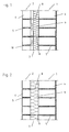
- Fig. 1 shows a clam shell masonry with air layer of an inner shell 1 and a distance set in front of outer shell 2 and a gap 3 between inner shell 1 and outer shell 2.
- the inner shell 1 is in the usual way by a masonry formed of superimposed mortared blocks 4, wherein between the blocks 4 corresponding, filled with mortar bearing joints are present, which are denoted by 5.
- the outer shell 2 is formed of masonry and indeed from one another mortared clinker bricks 6. Again, the bearing joint is denoted by 5.
- the bearing joints 5 of the inner shell 1 are designated 8 fastening anchors introduced, which are usually formed by wire anchors, such as one-piece rod-like anchor.
- wire anchors such as one-piece rod-like anchor.
- the outer shell 2 is held against the inner shell 1 and fixed.
- the wire anchors 8 fastened to the inner shell 1 extend into the bearing joints of the masonry of the outer shell 2.
- the thermal insulation here formed from an insulating panel 9 made of mineral wool.
- FIG. 1 describes a double-shell masonry with an air layer
- the outer shell 2 is set at a distance by mortaring the clinker bricks 6 one above the other.
- the corresponding joints are height aligned with each other, so that the outwardly projecting wire anchor 8 are grouted with and about the outer shell 2 is fixed relative to the inner shell 1.
- the air layer of the masonry according to FIG. 1 is denoted by 10 and serves for rear ventilation. The air flow is symbolized by an arrow.
- Fig. 2 shows a core insulation using a corresponding mineral wool plate 9, wherein in this figure the same reference numerals have been used for the same components.
- the core insulation formed from a thermal insulation panel 9 made of mineral wool fills the space between the two shells 1 and 2 completely, although for processing technical reasons in the core insulation not shown in the drawing distance of about 1 cm between the outside thermal insulation and the inside outer shell or veneer 2 is kept free, which is generally not aerated.
- the attachment of the insulation board 9 made of mineral wool merely by putting the insulation board on the previously introduced into the bearing joints of the inner shell 1 wire anchor 8, which act as Aufstecksp fauxe.
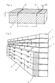
- the thermal insulation system Since the building blocks of the masonry, ie the inner shell 1 are in standard sizes, there is a uniform distance between the wire anchors of adjacent bearing joints in the stacked wire joints 8 inserted wire anchor 8 and so to speak a horizontal corridor whose height of 250 mm the standard stone size including bearing joint of the inner shell 1 corresponds.
- the mounting of the insulation boards or insulation boards is no longer by plugging on the wire anchor 8, but the insulation elements are adjusted in width B the height spacing of adjacent stacked rows of introduced into the corresponding bearing joints 5 wire anchors 8, preferably with a Oversize of 5 mm.
- the insulating elements which may be in the form of insulation boards 11 or insulation boards 12 are due to the adjusted or matched width dimension B press between the rows of stacked wire armature 8, so to speak placed in the corridors between the wire anchors and indeed introduced between the wire anchor 8 press , Due to the existing excess, the insulating elements 11, 12 fixed in this case by clamping action between the wire anchors 8 in their position and held against the inner shell 1. They only need to be inserted between the wire anchors 8 and pressed against the outer surface of the inner shell 1. Another assembly effort greater effort is unnecessary. As a result, the insulating elements 11, 12 are exactly joint-wise aligned and arranged one above the other, so that an oblique orientation or the like.
- the insulating elements 11, 12 have a width of 255 mm under inclusion of an excess of 5 mm .
- the insulation elements can be pressed between the wire anchors , are held there and form a thermal bridge-free composite also in the area of their joints.
- the outer shell 2 can then be bricked up or set in the conventional manner, with or without ventilation.
- the width of the insulating elements is aligned with the Baurichtstock, which is 12.5 cm according to DIN 4172, i. the width is an integer multiple of the construction dimension (height of stone and mortar joint). In this case, preferred widths are 125 mm, 250 mm, 375 mm, 500 mm and 625 mm. Although only one insulating element is provided between adjacent rows of wire anchors arranged on top of each other with reference to the preferred embodiment described in FIG . Per corridor also several insulating elements are arranged one above the other.
- both insulation boards 11 and insulation boards 12 can be used separately or together per object.
- Fig. 4 shows an insulating element in the form of a foam plate 14 made of EPS, in which recesses 16 are introduced at the upper longitudinal surface, in a longitudinal distance L to each other. That is, in this embodiment, the arrangement of the wire anchors is given by these recesses as a kind of template.
- the width BR of the recesses 16 is in this case matched to the diameter of the wire anchors and is usually in the range of 3 to 5 mm.
- the depth T of the recesses 16 corresponds at least to the diameter of the wire anchors.
- the longitudinal distance L between the recesses 16 is about 75 cm.
- Fig. 5 shows the assembled arrangement of the insulating elements and in the upper two rows of recesses 16 insulating boards 15 and provided in the lower two rows with recesses 16 insulation boards.
- the walling of the inner shell takes place simultaneously with the attachment of the insulation, wherein the wire anchors are inserted by utilizing the template function of the insulating elements in their predetermined recesses. Thereafter, the fixing of the inserted wire anchors by the bricking of the next stone layer, and at the same time serving as a template insulation elements in the form of a clamp.
- the outer shell is then in turn pre-set in a conventional manner, wherein the protruding wire anchors are embedded in the joints.
- Fig. 6 shows the embodiment of a thermal insulation system with insulating elements, which are provided with recesses 16, wherein in this embodiment, the superior outer shell 2 and the gap 3 is shown.
- the insulating material webs are conveniently kept ready in roll form and in lengths preferably from 2,000 mm to 10,000 mm.
- the strip-shaped insulation boards are preferably kept in lengths of 1,000 mm to 2,000 mm.
- the insulation boards and insulation boards can be laminated on one or both sides. As lamination is suitable, for example a glass fleece.
Abstract
Description
Die Erfindung betrifft ein Wärmedämmsystem für zweischalige Außenwände, sowie hierfür geeignete Dämmelemente.The invention relates to a thermal insulation system for clam shell exterior walls, as well as suitable insulation elements.
Entsprechende Wärmedämmsysteme sind allgemein bekannt (vgl. DE 35 46 968 C2). Diese Wärmedämmsysteme werden für zweischalige Außenwände mit mindestens einer zwischen den Schalen angeordneten Dämmschicht mit und ohne Hinterlüftung und für eine Kerndämmung in Mauerwerksbauweise verwendet. Hierbei werden Drahtanker als Befestigungsmittel verwendet, die in Lagerfugen der aus Bausteinen aufgemörtelten Innenschalen eingebracht sind. Diese Drahtanker stehen hierbei entsprechend weit über die Außenfläche der Innenschale vor, so dass sie zur Halterung der danach mit Abstand vorgesetzten Außenschale dienen können, die in der Regel als Verblendmauerwerk aus Vormauerziegeln oder Klinkern erstellt wird.Corresponding thermal insulation systems are generally known (cf., DE 35 46 968 C2). These thermal insulation systems are used for clam shell exterior walls with at least one between the shells arranged insulation layer with and without ventilation and for a core insulation in masonry construction. In this case, wire anchors are used as fastening means, which are introduced into bearing joints of the mortared from blocks inner shells. These wire anchors are in this case correspondingly far beyond the outer surface of the inner shell, so that they can serve to hold the then by far superior outer shell, which is usually created as a facing masonry of facing bricks or clinker.
Die Wärmedämmung erfolgt durch Wärmedämmplatten oder Wärmedämmbahnen, die in den Zwischenraum zwischen Innenschale und Außenschale angeordnet werden. Hierbei werden die Dämmelemente nach Erstellung der Innenschale auf die vorstehenden Drahtanker von außen aufgesetzt, welche die Dämmelemente spießartig durchdringen. Anschließend wird das Verblendmauerwerk erstellt. Im Falle eines zweischaligen Mauerwerks mit ruhender Luftschicht ist ein vom Planer vorgegebener Abstand zwischen Dämmplatte und Verblendmauerwerk freigehalten ("ohne Hinterlüftung"). Für ein zweischaliges Mauerwerk mit bewegter Luftschicht sind zusätzlich Lüftungsöffnungen in der Außenschale vorgesehen ("mit Hinterlüftung"). Im Falle eines zweischaligen Mauerwerks mit Kerndämmung füllt dagegen das Wärmedämmelement den Zwischenraum zwischen Außenschale und Innenschale im wesentlichen vollständig aus, wobei jedoch aus verarbeitungstechnischen Gründen im Falle der Kerndämmung noch ein minimaler Abstand von 10 mm zwischen Außenseite Wärmedämmung und Innenseite Verblendschale freigehalten wird, der jedoch nicht durchlüftet wird (vgl. insgesamt auch DIN-Norm 1053).The thermal insulation is carried out by thermal insulation boards or thermal insulation webs, which are arranged in the space between the inner shell and outer shell. Here, the insulation elements are placed after creating the inner shell on the protruding wire anchors from the outside, which penetrate the insulation elements like a spit. Then the facing brickwork is created. In the case of a double-shell masonry with a static air layer, a distance between the insulation board and the facing brickwork specified by the planner is kept free ("without ventilation"). For a double-shell masonry with a moving air layer, additional ventilation openings are provided in the outer shell ("with rear ventilation"). In the case of a clam shell masonry with core insulation, however, the thermal element fills the gap between the outer shell and inner shell substantially completely, but for processing technical reasons in the case of core insulation still a minimum distance of 10 mm between the outside thermal insulation and inside veneer is kept free, but not is ventilated (see in total also DIN standard 1053).
Bekannte Abmessungen der z.B. aus Glaswolle oder Steinwolle gefertigten Wärmedämmplatten für zweischaliges Mauerwerk und Kerndämmungen betragen etwa 1.200 mm x 625 mm. Zur Befestigung an der Innenschale werden diese Dämmplatten auf die von der Außenfläche der Innenschale vorstehenden Drahtanker spießartig aufgesteckt, so dass also die Drahtanker die Wärmedämmplatten durchstoßen. Da in der Praxis die über die Außenfläche der Innenschale vorstehenden Drahtanker häufig leicht abgeknickt oder gebogen sind, kann es beim Aufstecken der Wärmedämmplatten häufig zu einer ungenauen Ausrichtung der aufgesteckten und über die Drahtanker schließlich gegen die Außenfläche der Innenschale gedrückten Wärmedämmplatten kommen, was zur Folge hat, dass zwischen den benachbarten Wärmedämmplatten vielfach Fugen verbleiben, die Wärmebrücken bilden. Wollte man diese Wärmebrücken ausschließen, dann müssten die verbleibenden Spalte mit Dämmmaterial zusätzlich gefüllt werden, was einen weiteren Arbeitsvorgang mit sich bringt. Deswegen wird vielfach eine zweilagige Anbringung von Wärmedämmplatten bevorzugt, um mögliche Wärmebrücken aufgrund unzureichenden Plattenstößen zu vermeiden. Diese Praxis hat sich durchaus bewährt, ist jedoch zeit- und kostenaufwändig.Known dimensions of e.g. Heat insulation panels made of glass wool or rockwool for double-shell masonry and core insulation are approximately 1,200 mm x 625 mm. For attachment to the inner shell of these insulation boards are pegged attached to the protruding from the outer surface of the inner shell wire anchor so that so the wire anchors pierce the thermal insulation boards. Since in practice over the outer surface of the inner shell projecting wire anchors are often bent or bent slightly, it can often lead to an inaccurate alignment of the plugged and finally over the wire armature against the outer surface of the inner shell pressed thermal insulation panels when attaching the thermal insulation panels, which has the consequence that between the adjacent thermal insulation panels often remain joints that form thermal bridges. If one wanted to exclude these thermal bridges, then the remaining gaps would have to be additionally filled with insulating material, which brings about a further working process. For this reason, a two-layer attachment of thermal insulation panels is often preferred in order to avoid possible thermal bridges due to insufficient panel joints. This practice has proven itself, but is time consuming and costly.
Aufgabe der Erfindung ist es, ein Wärmedämmsystem für zweischalige Außenwände sowie ein hierfür geeignetes Dämmelement zu schaffen, welches bei einfacher Montage das Auftreten von Wärmebrücken im Bereich von Stößen zwischen den Dämmelementen vermeidet und zwar bei einfachem Aufbau und einfacher Herstellung und Handling der Dämmelemente.The object of the invention is to provide a thermal insulation system for clam shell outer walls and a suitable insulation element, which avoids the occurrence of thermal bridges in the range of shocks between the insulation elements with a simple installation and that with a simple structure and ease of manufacture and handling of the insulation elements.
Diese Aufgabe wird erfindungsgemäß durch die im kennzeichnenden Teil des Anspruchs 1 enthaltenen Merkmale gelöst, wobei zweckmäßige Weiterbildungen der Erfindung durch die in den Unteransprüchen enthaltenen Merkmale gekennzeichnet sind.This object is achieved by the features contained in the characterizing part of
Die Erfindung geht von der Überlegung aus, dass bei einem Bau eines zweischaligen Mauerwerks nach DIN 1053 in Folge der genormten Steinbaumaße die übereinander angeordneten Lagerfugen gleichmäßige Abstände in der Vertikalen zueinander aufweisen. Im Falle eines Steinmaßes von etwa 23,8 cm, wird dieser Abstand etwa 25 cm betragen. Dadurch ergeben sich zwischen benachbarten übereinander angeordneten Reihen von Drahtankern, die in den entsprechenden Lagerfugen verlegt sind, sozusagen horizontale Korridore, die aufgrund der genormten Steinmaße immer einen etwa gleichen vertikalen Abstand, hier exemplarisch 25 cm, aufweisen. Die Erfindung nutzt nun diese Korridore, indem sie anstelle von auf die Drahtanker aufsteckbaren Dämmelementen entsprechend auf die Breite der Korridore angepasste Dämmelemente verwendet, die in ihrer Breite derart auf den vertikalen Abstand benachbarter übereinander angeordneter Reihen von Befestigungsankern abgestimmt sind, dass die Dämmelemente in die Korridore eingesetzt und an der Außenfläche der Innenschale zwischen den Drahtankern press durch Klemmwirkung gehalten sind. Dadurch können die Dämmelemente selbst bei nicht geradlinig, sondern schief ausgerichteten oder gebogenen Drahtankern fugenfrei zu benachbarten Dämmelementen gegen die Außenfläche der Innenschale gedrückt werden, so dass Wärmebrücken zwischen benachbarten Dämmelementen zuverlässig vermieden werden. Dadurch sind gesonderte Maßnahmen durch Verfüllen etwaiger vorhandener Fugen entbehrlich und es genügt auch eine einlagige Anordnung der Dämmelemente. Zudem ist die Montage denkbar einfach, weil die Dämmelemente nicht mehr auf die Drahtanker aufgespießt, sondern nur in die Korridore eingesetzt werden müssen.The invention is based on the consideration that in a construction of a double-shell masonry according to DIN 1053 in consequence of the standardized stone construction dimensions, the stacked bearing joints have uniform distances in the vertical to each other. In the case of a stone measure of about 23.8 cm, this distance will be about 25 cm. This results between adjacent stacked rows of wire anchors, which are laid in the corresponding bearing joints, so to speak horizontal corridors, the due to the standardized stone dimensions always have an approximately equal vertical distance, here exemplarily 25 cm. The invention now uses these corridors by using according to the width of the corridors adapted insulation elements instead of matched to the wire anchor insulation elements, which are matched in width to the vertical spacing of adjacent superimposed rows of mounting anchors that the insulation elements in the corridors used and pressed on the outer surface of the inner shell between the wire anchors are held by clamping action. As a result, the insulating elements can be pressed without joints to neighboring insulating elements against the outer surface of the inner shell even with not rectilinear, but obliquely oriented or bent wire anchors, so that thermal bridges between adjacent insulation elements are reliably avoided. As a result, separate measures by filling any existing joints are unnecessary and it is sufficient, a single-layer arrangement of the insulation elements. In addition, the installation is very simple, because the insulation elements no longer skewered on the wire anchors, but only in the corridors must be used.
Zweckmäßigerweise werden die Dämmelemente des Wärmedämmsystems mit einem von deren Breite abhängigen Übermaß, vorzugsweise kleiner gleich 15 mm bereitgestellt, z.B bei einer Breite von 250 mm bevorzugt etwa 5 mm, wodurch in einfacher Weise ein zuverlässiger fugenfreier Verbund zwischen den Dämmelementen gewährleistet ist. Zudem ist hierdurch eine besonders gute Klemmwirkung zwischen den Drahtankern gewährleistet. Die derart zwischen die Drahtanker bzw. in die Korridore eingesetzten streifenartigen Dämmbahnen oder Dämmplatten sind somit sicher gegenüber der Innenschale lagefixiert und gehalten. Aufgrund dieser Klemmcharakteristik ergänzen sich die über- und nebeneinander angeordneten Dämmelemente zu einem geschlossenen Aufbau ohne Fugen entsprechend eines einlagigen Aufbaus einer Dämmschicht. Zudem kann auf zusätzliche Befestigungsmittel, wie Verklebung, verzichtet werden, was erhebliche Montage- und auch Kostenvorteile bringt.Conveniently, the insulating elements of the thermal insulation system with an over-dependent on its width oversize, preferably smaller than 15 mm provided, for example, with a width of 250 mm, preferably about 5 mm, which ensures a reliable joint-free bond between the insulation elements in a simple manner. In addition, this ensures a particularly good clamping action between the wire anchors. The strip-like insulation boards or insulation boards thus inserted between the wire anchors or in the corridors are thus securely fixed in position and held in relation to the inner shell. Because of this clamping characteristic, the over and next to each other arranged insulating elements complement each other to a closed structure without joints corresponding to a single-layer structure of an insulating layer. In addition, can be dispensed with additional fasteners, such as bonding, which brings significant installation and cost advantages.
Zweckmäßigerweise beträgt die Breite der Dämmelemente über die Länge des Dämmelements einem ganzzahligen Vielfachen eines Baurichtmaßes, insbesondere nach DIN 4172 entsprechend dem Abstand der höhenmäßig benachbarten Drahtanker in der Innenschale, wobei zweckmäßigerweise von dem Baurichtmaß nach DIN 4172 von 12,5 cm ausgegangen wird, also die Breite der Dämmelemente 12,5 cm, 25 cm, 37,5 cm, 50 cm oder 62,5 cm betragen kann, als einem ganzzahligen Vielfachen der Höhe einer Steinlage zusätzlich Höhe der Mörtelfuge.Advantageously, the width of the insulating elements over the length of the Dämmelements an integer multiple of a Baurichtmaßes, in particular according to DIN 4172 according to the distance of the heightwise adjacent wire anchor in the inner shell, which is expediently assumed by the Baurichtmaß to DIN 4172 of 12.5 cm, so the width of the insulating elements 12.5 cm, 25 cm, 37.5 cm, 50 cm or 62.5 cm may be as an integer multiple of the height a stone layer additionally height of the mortar joint.
In dem Fall, dass das Dämmelement aus Glaswolle gebildet ist, ist es zweckmäßig, das Dämmelement in einer Rohdichte von 7 bis 40 kg/m3, bevorzugt 10 bis 25 kg/m3 auszubilden. Dieser Rohdichtebereich erlaubt ein einfaches Handling auf der Baustelle und garantiert eine ausreichende Klemmwirkung im Falle eines entsprechenden Übermaßes. Im Falle von Steinwolle weist das Dämmelement zweckmäßigerweise eine Rohdichte im Bereich von 20 bis 100 kg/m3, bevorzugt im Bereich von 25 bis 70 kg/m3 auf. Die Einstellung einer Klemmcharakteristik bei Dämmstoffelementen aus Mineralwolle ist prinzipiell bekannt. Hierzu weisen diese Dämmstoffelemente einen erhöhten Bindemittelgehalt von etwa 6-7 Gew.-% bei Glaswolle und etwa 3,5 bis 4 % bei Steinwolle auf. Diese Dämmelemente werden häufig als Klemmfilze bezeichnet und sind von steifem Aufbau, dergestalt, dass insbesondere auch eine Verlegung mit bleibendem Luftspalt realisiert werden kann.In the case that the insulating element is formed of glass wool, it is expedient to form the insulating element in a bulk density of 7 to 40 kg / m 3 , preferably 10 to 25 kg / m 3 . This gross density range allows easy handling on the construction site and guarantees a sufficient clamping effect in the event of a corresponding oversize. In the case of rock wool, the insulating element expediently has a bulk density in the range of 20 to 100 kg / m 3 , preferably in the range of 25 to 70 kg / m 3 . The setting of a clamping characteristic with insulating elements made of mineral wool is known in principle. For this purpose, these insulating elements have an increased binder content of about 6-7 wt .-% in glass wool and about 3.5 to 4% in rock wool. These insulating elements are often referred to as Klemmfilze and are of rigid construction, such that in particular a laying with a permanent air gap can be realized.
Zweckmäßigerweise sind die Dämmelemente hydrophiert, insbesondere vollständig hydrophobiert, so dass eine einwandfreie Wasserableitung gewährleistet ist.Conveniently, the insulating elements are hydrophobic, in particular completely hydrophobic, so that a perfect drainage of water is ensured.
Unter praktischen Gesichtspunkten werden die Dämmelemente im Falle von Dämmbahnen in Längen von 2.000 bis 10.000 mm verwendet, z.B. in Form einer aufgewickelten Rolle. Im Falle einer streifenförmigen Dämmplatte eignen sich bevorzugt Längen im Bereich von 1.000 bis 2.000 mm.In practical terms, the insulating elements are used in the case of insulating strips in lengths of 2,000 to 10,000 mm, e.g. in the form of a wound roll. In the case of a strip-shaped insulation board preferably lengths in the range of 1,000 to 2,000 mm are suitable.
In einer zweckmäßigen Weiterbildung der Erfindung insbesondere für Schaumdämmstoffe wie EPS, XPS, PUR, PE oder dergleichen bzw. Mineralwolle mit höheren Rohdichten sind an mindestens einer den Befestigungsankern zugewandten Längsfläche des Dämmelements Einschnitte oder Ausnehmungen vorgesehen, die in Abständen zueinander angeordnet sind. Das Abstandsmaß gibt hierbei den seitlichen Abstand der Drahtanker in der Innenschale vor, d.h. bei dieser Ausbildung der Dämmelemente ergibt sich eine Montagefunktion, da die Dämmelemente als "verlorene" Schablone für die Drahtanker verwendet werden, was allerdings dann bedeutet, dass das Aufmauern der Hinterschale gleichzeitig mit dem Anbringen der Dämmung zu erfolgen hat, und die Drahtanker die vorgegebenen Einschnitte oder Ausnehmungen durchgreifen...In an expedient development of the invention in particular for foam insulation materials such as EPS, XPS, PUR, PE or the like or mineral wool with higher densities incisions or recesses are provided on at least one of the fastening anchors facing longitudinal surface of the Dämmelements, which are arranged at intervals to each other. The distance here indicates the lateral distance of the wire anchors in the inner shell, ie in this design of the insulating elements results in a mounting function, since the insulation elements are used as a "lost" template for the wire anchors, but what then means that the walling of the rear shell has to be done simultaneously with the attachment of the insulation, and the wire anchors to pass through the predetermined cuts or recesses ...
Die Dämmelemente für den Einsatz des Wärmedämmsystems zeichnen sich durch entsprechende Bemessung der Breite der Dämmelemente in Anpassung an den Lagerfugenabstand der Innenschale aus, so dass die Dämmelemente zwischen benachbarten Reihen der nach außen über die Innenschale vorstehenden Drahtanker gesetzt werden können.The insulation elements for use of the thermal insulation system are characterized by appropriate dimensioning of the width of the insulating elements in adaptation to the bearing joint spacing of the inner shell, so that the insulation elements between adjacent rows of outwardly over the inner shell projecting wire anchor can be set.
In vorteilhafter Weise können auch vlieskardierte Dämmelemente verwendet werden, bei denen mindestens eine der beiden Hauptflächen mit einer Deckschicht aus insbesondere Glasfaservlies versehen ist.Advantageously, nonwoven carded insulating elements can be used in which at least one of the two main surfaces is provided with a cover layer of glass fiber fleece in particular.
Nachfolgend werden Ausführungsbeispiele der Erfindung anhand der rein schematisch dargestellten Zeichnung beschrieben. Darin zeigen
- Fig. 1
- eine Schnittansicht eines zweischaligen Mauerwerks mit hinterlüfteter Luftschicht,
- Fig. 2
- eine Schnittansicht eines zweischaligen Mauerwerks mit Kemdämmung,
- Fig. 3
- eine perspektivische Ansicht einer erfindungsgemäßen Ausführungsform eines Wärmedämmsystems,
- Fig. 4
- eine Ausführungsform eines Dämmelements mit Ausnehmungen,
- Fig. 5
- eine schematische Darstellung eines Teils eines Wärmedämmsystems der Erfindung mit Dämmelementen nach Fig. 4 sowie
- Fig. 6
- eine perspektivische Darstellung eines Wärmedämmsystems mit Dämmelementen nach Fig. 4.
- Fig. 1
- a sectional view of a two-shell masonry with ventilated air layer,
- Fig. 2
- a sectional view of a double-shell masonry with insulation,
- Fig. 3
- a perspective view of an embodiment of a thermal insulation system according to the invention,
- Fig. 4
- an embodiment of an insulating element with recesses,
- Fig. 5
- a schematic representation of a portion of a thermal insulation system of the invention with insulating elements of FIG. 4 and
- Fig. 6
- a perspective view of a thermal insulation system with insulation elements of FIG .. 4
Fig. 1 zeigt ein zweischaliges Mauerwerk mit Luftschicht aus einer Innenschale 1 und einer mit Abstand davor gesetzten Außenschale 2 und einem Zwischenraum 3 zwischen Innenschale 1 und Außenschale 2. Die Innenschale 1 ist in der üblichen Weise durch ein Mauerwerk aus übereinander gemörtelten Bausteinen 4 gebildet, wobei zwischen den Bausteinen 4 entsprechende, mit Mörtel gefüllte Lagerfugen vorhanden sind, die mit 5 bezeichnet sind.Fig. 1 shows a clam shell masonry with air layer of an
Auch die Außenschale 2 ist aus Mauerwerk gebildet und zwar aus übereinander gemörtelten Klinkersteinen 6. Auch hier ist die Lagerfuge mit 5 bezeichnet. In die Lagerfugen 5 der Innenschale 1 sind mit 8 bezeichnete Befestigungsanker eingebracht, die üblicherweise durch Drahtanker, etwa einteilige stabartige Anker, gebildet sind. Über diese Drahtanker 8 wird die Außenschale 2 gegenüber der Innenschale 1 gehalten und fixiert. Entsprechend erstrecken sich die an der Innenschale 1 befestigten Drahtanker 8 in die Lagerfugen des Mauerwerks der Außenschale 2. Im Zwischenraum 3 zwischen den beiden Schalen befindet sich die Wärmedämmung, hier gebildet aus einer Dämmplatte 9 aus Mineralwolle. Zur Bildung des Mauerwerks wird zuerst die Innenschale 1 mit den Mauersteinen 4 aufgemauert, wobei in die Fugen die Drahtanker 8 eingebracht werden. Auf die nach außen vorstehenden Drahtanker 8 wird dann in konventioneller Bauart die Wärmedämmplatte 9 aufgesteckt, wobei die Drahtanker 8 die Wärmedämmplatte spießartig durchdringen. Dadurch ist die Wärmedämmplatte 9 gegenüber der Innenschale 1 lagefixiert und gehalten. Schließlich wird, da Fig. 1 ein zweischaliges Mauerwerk mit Luftschicht beschreibt, die Außenschale 2 mit Abstand vorgesetzt, indem die Klinkersteine 6 übereinander gemörtelt werden. Hierbei sind die entsprechenden Fugen höhenmäßig miteinander ausgerichtet, so dass die nach außen hin vorstehenden Drahtanker 8 mit eingemörtelt werden und darüber die Außenschale 2 gegenüber der Innenschale 1 fixiert ist. Die Luftschicht des Mauerwerks nach Fig. 1 ist hierbei mit 10 bezeichnet und dient der Hinterlüftung. Die Luftströmung ist hierbei durch Pfeil symbolisiert.The
Fig. 2 zeigt eine Kerndämmung unter Verwendung einer entsprechenden Mineralwolleplatte 9, wobei in dieser Figur für dieselben Bauteile dieselben Bezugszeichen verwendet worden sind. Ersichtlich füllt die aus einer Wärmedämmplatte 9 aus Mineralwolle gebildete Kerndämmung den Zwischenraum 3 zwischen den beiden Schalen 1 und 2 vollständig aus, wenngleich aus verarbeitungstechnischen Gründen bei der Kerndämmung ein in der Zeichnung nicht dargestellter Abstand von ca. 1 cm zwischen Außenseite Wärmedämmung und Innenseite Außenschale 2 bzw. Verblendschale 2 freigehalten wird, der generell nicht durchlüftet wird. Auch hier erfolgt die Befestigung der Dämmplatte 9 aus Mineralwolle durch bloßes Aufstecken der Dämmplatte auf die zuvor in die Lagerfugen der Innenschale 1 eingebrachten Drahtanker 8, die als Aufsteckspieße wirken.Fig. 2 shows a core insulation using a corresponding
Bei der Ausführungsform nach Fig. 3, bei der die Innenschale wiederum mit 1 bezeichnet ist, sind ebenso wie im Falle der Figuren 1 und 2 entsprechende Drahtanker bzw. Befestigungsanker 8 in übereinander angeordneten Fugen des Mauerwerks eingebracht und stehen über die Außenfläche der Innenschale 1 entsprechend weit vor, um einen Verbund mit der in Fig. 3 nicht dargestellten Verblendschale bzw. Außenschale zu bilden. Auch hier sind die Drahtanker entsprechend in die Lagerfugen eingelegt (gemäß Vorgabe DIN 1053). Ersichtlich sind bei dieser gemäß DIN 1053 ausgeführten Innenschale 1 die pro Quadratmeter statisch erforderlichen Drahtanker in der Vertikalen in gleichmäßig beabstandeten Reihen, nämlich in die gleichmäßig beabstandeten Lagerfugen eingebracht. Da die Bausteine des Mauerwerks, d. h. der Innenschale 1 in normgerechten Größen vorliegen, ergibt sich ein gleichmäßiger Abstand der in die übereinander angeordneten Lagerfugen 5 eingelegten Drahtanker 8 und damit zwischen den Drahtankern benachbarter Lagerfugen sozusagen ein horizontaler Korridor, dessen Höhe von 250 mm dem genormten Steinmaß inklusive Lagerfuge der Innenschale 1 entspricht. Im erfindungsgemäßen Wärmedämmsystem erfolgt die Halterung der Dämmplatten oder Dämmbahnen nicht mehr durch Aufstecken auf die Drahtanker 8, vielmehr sind die Dämmelemente in ihrer Breite B dem höhenmäßigen Abstand benachbarter übereinander angeordneter Reihen von in den entsprechenden Lagerfugen 5 eingebrachten Drahtankern 8 angepasst, und zwar bevorzugt mit einem Übermaß von 5 mm. Die Dämmelemente, die in Form von Dämmplatten 11 oder Dämmbahnen 12 vorliegen können, werden aufgrund der angepassten bzw. abgestimmten Breitenabmessung B press zwischen die Reihen übereinander angeordneter Drahtanker 8, also sozusagen in die Korridore zwischen den Drahtankern gelegt und zwar press zwischen die Drahtanker 8 eingebracht. Aufgrund des vorhandenen Übermaßes werden die Dämmelemente 11, 12 hierbei durch Klemmwirkung zwischen den Drahtankern 8 fest in ihrer Lage fixiert und gegenüber der Innenschale 1 gehalten. Sie brauchen lediglich zwischen die Drahtanker 8 eingesetzt und gegen die Außenfläche der Innenschale 1 gedrückt zu werden. Eine weitere Montagemaßnahme größeren Aufwands ist entbehrlich. Dadurch werden die Dämmelemente 11, 12 exakt fugenweise ausgerichtet und übereinander angeordnet, so dass eine Schrägausrichtung oder dgl. selbst bei schief aus der Außenfläche der Innenschale 1 vorstehenden Drahtankern 8 ausgeschlossen ist. Dadurch sind die Fugen zwischen benachbarten Dämmelementen 11, 12 fest geschlossen, so dass Wärmebrücken vermieden werden. Dadurch reicht es, dass die Dämmplatten 11 oder Dämmbahnen 12 einlagig verlegt werden. Für die unterste Lage zwischen Perimeterdämmung und der ersten Ankerlage kann die unausgerollte Rolle auf dieses Maß in einfacher Weise zugeschnitten werden und anschließend kann die einfache Verlegung wie bei den anderen Rollen zwischen den Ankerreihen erfolgen.In the embodiment of Fig. 3, in which the inner shell is again denoted by 1, as in the case of Figures 1 and 2 corresponding wire anchors or
Im dargestellten Ausführungsbeispiel, also bei einem genormten Steinmaß der Steine 4 von 250 mm inklusive Lagerfuge der Innenschale 1 besitzen die Dämmelemente 11, 12 eine Breite von 255 mm unter Einberechnung eines Übermaßes von 5 mm.. Dadurch können die Dämmelemente press zwischen den Drahtankern eingelegt werden, werden dort gehalten und bilden einen wärmebrückenfreien Verbund auch im Bereich ihrer Stoßstellen. Nach Montage der Dämmelemente kann dann in der konventionellen Weise die Außenschale 2 aufgemauert bzw. vorgesetzt werden, und zwar mit oder ohne Hinterlüftung.In the illustrated embodiment, ie at a standardized stone size of the
Die Breite der Dämmelemente ist auf das Baurichtmaß ausgerichtet, welches nach DIN 4172 12,5 cm beträgt, d.h. die Breite ist ein ganzzahliges Vielfaches des Baurichtmaßes (Höhe Stein und Mörtelfuge). Bevorzugte Breiten sind hierbei 125 mm, 250 mm, 375 mm, 500 mm und 625 mm.. Zwar ist anhand des in Fig. 3 beschriebenen bevorzugten Ausführungsbeispiels jeweils nur ein Dämmelement zwischen benachbarten übereinander angeordneten Reihen von Drahtankern vorgesehen, jedoch können alternativ je Reihe bzw. je Korridor auch mehrere Dämmelemente übereinander angeordnet werden.The width of the insulating elements is aligned with the Baurichtmaß, which is 12.5 cm according to DIN 4172, i. the width is an integer multiple of the construction dimension (height of stone and mortar joint). In this case, preferred widths are 125 mm, 250 mm, 375 mm, 500 mm and 625 mm. Although only one insulating element is provided between adjacent rows of wire anchors arranged on top of each other with reference to the preferred embodiment described in FIG . Per corridor also several insulating elements are arranged one above the other.
Zum Beispiel bei einem Korridormaß B von 500 mm entsprechend der Anordnung in Fig. 3 könnten also jeweils zwei Dämmelemente übereinander je Korridor angeordnet werden, wenn diese auf die Breite von 250 mm zuzüglich Übermaß ausgelegt sind. Auch für diesen Fall, wenn also zwei Dämmelemente übereinander je Korridor angeordnet werden, ergibt sich eine feste Halterung der zwischen die Drahtanker eingebrachten Dämmelemente und ein lückenloser bzw. fugenloser und damit wärmebrückenfreier Verbund im Stoßflächenbereich der Dämmelemente.For example, in the case of a corridor dimension B of 500 mm corresponding to the arrangement in FIG. 3, it would thus be possible for two insulating elements to be arranged one above the other per corridor if they are designed for the width of 250 mm plus oversize. Also for this case, so if two insulating elements are arranged one above the other corridor, there is a firm support of introduced between the wire anchor insulation elements and a gapless or seamless and thus free of thermal bridges composite in the abutting surface of the insulation elements.
Wie in Fig. 3 dargestellt, können sowohl Dämmplatten 11 als auch Dämmbahnen 12 separat oder gemeinsam pro Objekt verwendet werden.As shown in Fig. 3, both
Fig. 4 zeigt ein Dämmelement in Form einer Schaumstoffplatte 14 aus EPS, bei der an der oberen Längsfläche Ausnehmungen 16 eingebracht sind, und zwar in einem Längenabstand L zueinander. D. h., bei dieser Ausführungsform wird die Anordnung der Drahtanker durch diese Ausnehmungen als eine Art Schablone vorgegeben. Die Breite BR der Ausnehmungen 16 ist hierbei auf den Durchmesser der Drahtanker abgestimmtund liegt hierbei üblicherweise im Bereich von 3 bis 5 mm. Die Tiefe T der Ausnehmungen 16 entspricht mindestens dem Durchmesser der Drahtanker. Im dargestellten Ausführungsbeispiel beträgt der Längsabstand L zwischen den Ausnehmungen 16 etwa 75 cm.Fig. 4 shows an insulating element in the form of a
Fig. 5 zeigt die montierte Anordnung der Dämmelemente und zwar in den oberen beiden Reihen mit Ausnehmungen 16 versehene Dämmbahnen 15 und in den unteren beiden Reihen mit Ausnehmungen 16 versehene Dämmplatten.Fig. 5 shows the assembled arrangement of the insulating elements and in the upper two rows of
Das Aufmauern der Innenschale erfolgt gleichzeitig mit dem Anbringen der Dämmung, wobei die Drahtanker unter Ausnutzung der Schablonenfunktion der Dämmelemente in deren vorgegebene Ausnehmungen eingelegt werden. Danach erfolgt die Fixierung der eingelegten Drahtanker durch das Aufmauern der nächsten Steinlage, und gleichzeitig der als Schablone dienenden Dämmelemente in Form einer Klemmung.The walling of the inner shell takes place simultaneously with the attachment of the insulation, wherein the wire anchors are inserted by utilizing the template function of the insulating elements in their predetermined recesses. Thereafter, the fixing of the inserted wire anchors by the bricking of the next stone layer, and at the same time serving as a template insulation elements in the form of a clamp.
Auch hier sind im Stoßstellenbereich keine Fugen vorhanden, die Wärmebrücken bilden können, da die Ausnehmungen 16 im Prinzip durch die durchgreifenden Drahtanker gefüllt, wobei die Ausnehmungen im übrigen entsprechend eng bemaßt werden, so dass beim Eintritt der Drahtanker die Wände der Einschnitte leicht verformen und danach wieder um die eingeführten Drahtanker zurückfedernd anliegen, so dass auch hier im Prinzip keine Wärmebrücken vorhanden sind.Again, no joints are present in the joint area, which can form thermal bridges, since the
Die Außenschale wird dann wiederum in konventioneller Weise vorgesetzt, wobei die vorstehenden Drahtanker in den Fugen eingebettet sind.The outer shell is then in turn pre-set in a conventional manner, wherein the protruding wire anchors are embedded in the joints.
Fig. 6 zeigt die Ausführungsform eines Wärmedämmsystems mit Dämmelementen, die mit Ausnehmungen 16 versehen sind, wobei in dieser Ausführungsform auch die vorgesetzte Außenschale 2 und der Zwischenraum 3 dargestellt ist.Fig. 6 shows the embodiment of a thermal insulation system with insulating elements, which are provided with
Die Dämmstoffbahnen werden zweckmäßigerweise in Rollenform bereitgehalten und zwar in Längen bevorzugt von 2.000 mm bis 10.000 mm. Die streifenförmigen Dämmplatten werden vorzugsweise in Längen von 1.000 mm bis 2.000 mm bereitgehalten. Die Dämmplatten und Dämmbahnen können ein oder beidseitig kaschiert sein. Als Kaschierung eignet sich z.B. ein Glasvlies.The insulating material webs are conveniently kept ready in roll form and in lengths preferably from 2,000 mm to 10,000 mm. The strip-shaped insulation boards are preferably kept in lengths of 1,000 mm to 2,000 mm. The insulation boards and insulation boards can be laminated on one or both sides. As lamination is suitable, for example a glass fleece.
Claims (18)
Priority Applications (1)
| Application Number | Priority Date | Filing Date | Title |
|---|---|---|---|
| PL05015003T PL1617001T3 (en) | 2004-07-12 | 2005-07-11 | Heat insulation system for an exterior cavity wall |
Applications Claiming Priority (1)
| Application Number | Priority Date | Filing Date | Title |
|---|---|---|---|
| DE102004033607A DE102004033607A1 (en) | 2004-07-12 | 2004-07-12 | Thermal insulation system for clam shell exterior walls |
Publications (3)
| Publication Number | Publication Date |
|---|---|
| EP1617001A2 true EP1617001A2 (en) | 2006-01-18 |
| EP1617001A3 EP1617001A3 (en) | 2006-11-08 |
| EP1617001B1 EP1617001B1 (en) | 2009-09-30 |
Family
ID=34979331
Family Applications (1)
| Application Number | Title | Priority Date | Filing Date |
|---|---|---|---|
| EP05015003A Not-in-force EP1617001B1 (en) | 2004-07-12 | 2005-07-11 | Heat insulation system for an exterior cavity wall |
Country Status (5)
| Country | Link |
|---|---|
| EP (1) | EP1617001B1 (en) |
| AT (1) | ATE444417T1 (en) |
| DE (2) | DE102004033607A1 (en) |
| DK (1) | DK1617001T3 (en) |
| PL (1) | PL1617001T3 (en) |
Cited By (4)
| Publication number | Priority date | Publication date | Assignee | Title |
|---|---|---|---|---|
| NL2001794C2 (en) * | 2008-07-11 | 2010-01-12 | Ecotherm Beheer B V | Insulation panel for cavity wall of building e.g. house, has two insulating surfaces formed between circumferential sides, where dimension of panel between circumferential sides is equivalent to anchor distance defined by cavity anchors |
| CN102071782A (en) * | 2011-01-11 | 2011-05-25 | 泉州市奇特艺工艺制品有限公司 | EPS (expandable polystyrene) light building material |
| BE1018967A3 (en) * | 2009-10-19 | 2011-12-06 | Douterloigne Nv | METHOD FOR ISOLATING A BUILDING AND BUILDING STONE APPLIED THEREOF |
| CN103206032A (en) * | 2013-03-28 | 2013-07-17 | 苏州市世好建材新技术工程有限公司 | Heat-insulation wall with low temperature difference |
Families Citing this family (2)
| Publication number | Priority date | Publication date | Assignee | Title |
|---|---|---|---|---|
| DE202011005374U1 (en) | 2011-04-16 | 2011-08-02 | Wilhelm Christian Koch | Device for thermal insulation of a building with vacuum insulation panels |
| CN113738070A (en) * | 2021-10-19 | 2021-12-03 | 烟台市顺达聚氨酯有限责任公司 | Heat preservation construction method and heat preservation structure for gaps of civil engineering refrigeration house |
Citations (3)
| Publication number | Priority date | Publication date | Assignee | Title |
|---|---|---|---|---|
| GB2033448A (en) * | 1978-10-10 | 1980-05-21 | Lite Pac Ltd | Wall tie supporting insulation in cavity wall |
| FR2558865A1 (en) * | 1984-01-30 | 1985-08-02 | Ortiz Antoine | Exterior insulating lining for a masonry wall |
| US5755070A (en) * | 1989-08-28 | 1998-05-26 | Hohmann Enterprises, Inc. | Multi veneer anchor structural assembly and drywall construction system |
Family Cites Families (3)
| Publication number | Priority date | Publication date | Assignee | Title |
|---|---|---|---|---|
| GB2069564B (en) * | 1980-02-20 | 1983-09-28 | Catnic Components Ltd | Wall tie for retaining cavity insulating material |
| GB2111095A (en) * | 1981-08-12 | 1983-06-29 | Glasgow Steel Nail Company Lim | Wall Tie |
| US6668505B1 (en) * | 2002-09-03 | 2003-12-30 | Hohmann & Barnard, Inc. | High-span anchors and reinforcements for masonry walls |
-
2004
- 2004-07-12 DE DE102004033607A patent/DE102004033607A1/en not_active Withdrawn
-
2005
- 2005-07-11 EP EP05015003A patent/EP1617001B1/en not_active Not-in-force
- 2005-07-11 PL PL05015003T patent/PL1617001T3/en unknown
- 2005-07-11 DE DE502005008224T patent/DE502005008224D1/en active Active
- 2005-07-11 AT AT05015003T patent/ATE444417T1/en not_active IP Right Cessation
- 2005-07-11 DK DK05015003T patent/DK1617001T3/en active
Patent Citations (3)
| Publication number | Priority date | Publication date | Assignee | Title |
|---|---|---|---|---|
| GB2033448A (en) * | 1978-10-10 | 1980-05-21 | Lite Pac Ltd | Wall tie supporting insulation in cavity wall |
| FR2558865A1 (en) * | 1984-01-30 | 1985-08-02 | Ortiz Antoine | Exterior insulating lining for a masonry wall |
| US5755070A (en) * | 1989-08-28 | 1998-05-26 | Hohmann Enterprises, Inc. | Multi veneer anchor structural assembly and drywall construction system |
Cited By (6)
| Publication number | Priority date | Publication date | Assignee | Title |
|---|---|---|---|---|
| NL2001794C2 (en) * | 2008-07-11 | 2010-01-12 | Ecotherm Beheer B V | Insulation panel for cavity wall of building e.g. house, has two insulating surfaces formed between circumferential sides, where dimension of panel between circumferential sides is equivalent to anchor distance defined by cavity anchors |
| BE1018967A3 (en) * | 2009-10-19 | 2011-12-06 | Douterloigne Nv | METHOD FOR ISOLATING A BUILDING AND BUILDING STONE APPLIED THEREOF |
| BE1019521A3 (en) * | 2009-10-19 | 2012-08-07 | Douterloigne Nv | METHOD FOR ISOLATING A BUILDING AND BUILDING STONE APPLIED THEREOF |
| CN102071782A (en) * | 2011-01-11 | 2011-05-25 | 泉州市奇特艺工艺制品有限公司 | EPS (expandable polystyrene) light building material |
| CN103206032A (en) * | 2013-03-28 | 2013-07-17 | 苏州市世好建材新技术工程有限公司 | Heat-insulation wall with low temperature difference |
| CN103206032B (en) * | 2013-03-28 | 2014-12-31 | 苏州市世好建材新技术工程有限公司 | Heat-insulation wall with low temperature difference |
Also Published As
| Publication number | Publication date |
|---|---|
| EP1617001B1 (en) | 2009-09-30 |
| DK1617001T3 (en) | 2009-12-21 |
| PL1617001T3 (en) | 2010-02-26 |
| DE502005008224D1 (en) | 2009-11-12 |
| EP1617001A3 (en) | 2006-11-08 |
| DE102004033607A1 (en) | 2006-02-16 |
| ATE444417T1 (en) | 2009-10-15 |
Similar Documents
| Publication | Publication Date | Title |
|---|---|---|
| EP2639394B1 (en) | Wall edge strip, window border and wall construction with wall edge strip | |
| EP1617001B1 (en) | Heat insulation system for an exterior cavity wall | |
| CH696546A5 (en) | Fastening element for fastening on building of insulating course and ventilated protective layer, has metal shaft inserted from outside into insulating course and with first and second load application elements on respective ends | |
| DE10147831B4 (en) | stud wall | |
| DE19951105C2 (en) | Heat and / or sound insulation element | |
| EP1707699A2 (en) | Ventilated and heat insulated building front | |
| EP2960392A1 (en) | Ceilings edge formwork element | |
| EP2067905B1 (en) | Prefabricated cladding element for an external wall near a window or door embrasure | |
| AT17112U1 (en) | Wall or roof cladding unit, wall and roof cladding system, in particular back-ventilated or rear-ventilated wall and roof cladding system, as well as wall, in particular wooden frame construction wall, and roof and use of the wall or roof cladding unit | |
| DE202012012901U1 (en) | edge form | |
| EP1327732B1 (en) | Edge shuttering for concrete slabs | |
| DE3214502C2 (en) | ||
| DE7625460U1 (en) | FINISHED ELEMENT | |
| EP2330259A2 (en) | Cladding element for an external wall | |
| EP0201757A3 (en) | Façade coating, in particular for the restoration of old buildings | |
| EP1918469B1 (en) | Composite heat insulation system | |
| EP3091167A1 (en) | Fastening element for attaching a window frame to a ceiling of a structure, associated structure and method for fixing a frame of a window to a ceiling | |
| AT13485U1 (en) | Isolated building facade | |
| DE202017107471U1 (en) | Slab edge formwork element | |
| DE102013003796A1 (en) | System for the fire protection of buildings | |
| EP1264943B1 (en) | Wall, ceiling and sound proofing element | |
| AT522813B1 (en) | formwork element | |
| AT525083B1 (en) | Kit for an attic structure on a building | |
| DE102005025517B4 (en) | Corner bandage for insulation boards | |
| AT397400B (en) | Connecting element for the layers of a multi-layer masonry structure |
Legal Events
| Date | Code | Title | Description |
|---|---|---|---|
| PUAI | Public reference made under article 153(3) epc to a published international application that has entered the european phase |
Free format text: ORIGINAL CODE: 0009012 |
|
| AK | Designated contracting states |
Kind code of ref document: A2 Designated state(s): AT BE BG CH CY CZ DE DK EE ES FI FR GB GR HU IE IS IT LI LT LU LV MC NL PL PT RO SE SI SK TR |
|
| AX | Request for extension of the european patent |
Extension state: AL BA HR MK YU |
|
| PUAL | Search report despatched |
Free format text: ORIGINAL CODE: 0009013 |
|
| AK | Designated contracting states |
Kind code of ref document: A3 Designated state(s): AT BE BG CH CY CZ DE DK EE ES FI FR GB GR HU IE IS IT LI LT LU LV MC NL PL PT RO SE SI SK TR |
|
| AX | Request for extension of the european patent |
Extension state: AL BA HR MK YU |
|
| 17P | Request for examination filed |
Effective date: 20070115 |
|
| 17Q | First examination report despatched |
Effective date: 20070219 |
|
| AKX | Designation fees paid |
Designated state(s): AT BE BG CH CY CZ DE DK EE ES FI FR GB GR HU IE IS IT LI LT LU LV MC NL PL PT RO SE SI SK TR |
|
| GRAP | Despatch of communication of intention to grant a patent |
Free format text: ORIGINAL CODE: EPIDOSNIGR1 |
|
| GRAS | Grant fee paid |
Free format text: ORIGINAL CODE: EPIDOSNIGR3 |
|
| GRAA | (expected) grant |
Free format text: ORIGINAL CODE: 0009210 |
|
| AK | Designated contracting states |
Kind code of ref document: B1 Designated state(s): AT BE BG CH CY CZ DE DK EE ES FI FR GB GR HU IE IS IT LI LT LU LV MC NL PL PT RO SE SI SK TR |
|
| REG | Reference to a national code |
Ref country code: CH Ref legal event code: EP Ref country code: GB Ref legal event code: FG4D Free format text: NOT ENGLISH |
|
| REG | Reference to a national code |
Ref country code: IE Ref legal event code: FG4D |
|
| REF | Corresponds to: |
Ref document number: 502005008224 Country of ref document: DE Date of ref document: 20091112 Kind code of ref document: P |
|
| REG | Reference to a national code |
Ref country code: DK Ref legal event code: T3 |
|
| PG25 | Lapsed in a contracting state [announced via postgrant information from national office to epo] |
Ref country code: LT Free format text: LAPSE BECAUSE OF FAILURE TO SUBMIT A TRANSLATION OF THE DESCRIPTION OR TO PAY THE FEE WITHIN THE PRESCRIBED TIME-LIMIT Effective date: 20090930 Ref country code: FI Free format text: LAPSE BECAUSE OF FAILURE TO SUBMIT A TRANSLATION OF THE DESCRIPTION OR TO PAY THE FEE WITHIN THE PRESCRIBED TIME-LIMIT Effective date: 20090930 Ref country code: SE Free format text: LAPSE BECAUSE OF FAILURE TO SUBMIT A TRANSLATION OF THE DESCRIPTION OR TO PAY THE FEE WITHIN THE PRESCRIBED TIME-LIMIT Effective date: 20090930 |
|
| LTIE | Lt: invalidation of european patent or patent extension |
Effective date: 20090930 |
|
| PG25 | Lapsed in a contracting state [announced via postgrant information from national office to epo] |
Ref country code: LV Free format text: LAPSE BECAUSE OF FAILURE TO SUBMIT A TRANSLATION OF THE DESCRIPTION OR TO PAY THE FEE WITHIN THE PRESCRIBED TIME-LIMIT Effective date: 20090930 Ref country code: SI Free format text: LAPSE BECAUSE OF FAILURE TO SUBMIT A TRANSLATION OF THE DESCRIPTION OR TO PAY THE FEE WITHIN THE PRESCRIBED TIME-LIMIT Effective date: 20090930 |
|
| REG | Reference to a national code |
Ref country code: PL Ref legal event code: T3 |
|
| PG25 | Lapsed in a contracting state [announced via postgrant information from national office to epo] |
Ref country code: PT Free format text: LAPSE BECAUSE OF FAILURE TO SUBMIT A TRANSLATION OF THE DESCRIPTION OR TO PAY THE FEE WITHIN THE PRESCRIBED TIME-LIMIT Effective date: 20100201 Ref country code: IS Free format text: LAPSE BECAUSE OF FAILURE TO SUBMIT A TRANSLATION OF THE DESCRIPTION OR TO PAY THE FEE WITHIN THE PRESCRIBED TIME-LIMIT Effective date: 20100130 Ref country code: ES Free format text: LAPSE BECAUSE OF FAILURE TO SUBMIT A TRANSLATION OF THE DESCRIPTION OR TO PAY THE FEE WITHIN THE PRESCRIBED TIME-LIMIT Effective date: 20100110 Ref country code: EE Free format text: LAPSE BECAUSE OF FAILURE TO SUBMIT A TRANSLATION OF THE DESCRIPTION OR TO PAY THE FEE WITHIN THE PRESCRIBED TIME-LIMIT Effective date: 20090930 Ref country code: CZ Free format text: LAPSE BECAUSE OF FAILURE TO SUBMIT A TRANSLATION OF THE DESCRIPTION OR TO PAY THE FEE WITHIN THE PRESCRIBED TIME-LIMIT Effective date: 20090930 Ref country code: RO Free format text: LAPSE BECAUSE OF FAILURE TO SUBMIT A TRANSLATION OF THE DESCRIPTION OR TO PAY THE FEE WITHIN THE PRESCRIBED TIME-LIMIT Effective date: 20090930 |
|
| PG25 | Lapsed in a contracting state [announced via postgrant information from national office to epo] |
Ref country code: SK Free format text: LAPSE BECAUSE OF FAILURE TO SUBMIT A TRANSLATION OF THE DESCRIPTION OR TO PAY THE FEE WITHIN THE PRESCRIBED TIME-LIMIT Effective date: 20090930 Ref country code: CY Free format text: LAPSE BECAUSE OF FAILURE TO SUBMIT A TRANSLATION OF THE DESCRIPTION OR TO PAY THE FEE WITHIN THE PRESCRIBED TIME-LIMIT Effective date: 20090930 |
|
| PLBE | No opposition filed within time limit |
Free format text: ORIGINAL CODE: 0009261 |
|
| STAA | Information on the status of an ep patent application or granted ep patent |
Free format text: STATUS: NO OPPOSITION FILED WITHIN TIME LIMIT |
|
| 26N | No opposition filed |
Effective date: 20100701 |
|
| PG25 | Lapsed in a contracting state [announced via postgrant information from national office to epo] |
Ref country code: GR Free format text: LAPSE BECAUSE OF FAILURE TO SUBMIT A TRANSLATION OF THE DESCRIPTION OR TO PAY THE FEE WITHIN THE PRESCRIBED TIME-LIMIT Effective date: 20091231 |
|
| PG25 | Lapsed in a contracting state [announced via postgrant information from national office to epo] |
Ref country code: MC Free format text: LAPSE BECAUSE OF NON-PAYMENT OF DUE FEES Effective date: 20100731 |
|
| REG | Reference to a national code |
Ref country code: CH Ref legal event code: PL |
|
| PG25 | Lapsed in a contracting state [announced via postgrant information from national office to epo] |
Ref country code: IT Free format text: LAPSE BECAUSE OF FAILURE TO SUBMIT A TRANSLATION OF THE DESCRIPTION OR TO PAY THE FEE WITHIN THE PRESCRIBED TIME-LIMIT Effective date: 20090930 |
|
| REG | Reference to a national code |
Ref country code: FR Ref legal event code: ST Effective date: 20110331 |
|
| PG25 | Lapsed in a contracting state [announced via postgrant information from national office to epo] |
Ref country code: CH Free format text: LAPSE BECAUSE OF NON-PAYMENT OF DUE FEES Effective date: 20100731 Ref country code: LI Free format text: LAPSE BECAUSE OF NON-PAYMENT OF DUE FEES Effective date: 20100731 |
|
| PG25 | Lapsed in a contracting state [announced via postgrant information from national office to epo] |
Ref country code: FR Free format text: LAPSE BECAUSE OF NON-PAYMENT OF DUE FEES Effective date: 20100802 |
|
| PG25 | Lapsed in a contracting state [announced via postgrant information from national office to epo] |
Ref country code: AT Free format text: LAPSE BECAUSE OF NON-PAYMENT OF DUE FEES Effective date: 20100711 |
|
| PG25 | Lapsed in a contracting state [announced via postgrant information from national office to epo] |
Ref country code: HU Free format text: LAPSE BECAUSE OF FAILURE TO SUBMIT A TRANSLATION OF THE DESCRIPTION OR TO PAY THE FEE WITHIN THE PRESCRIBED TIME-LIMIT Effective date: 20100401 Ref country code: LU Free format text: LAPSE BECAUSE OF NON-PAYMENT OF DUE FEES Effective date: 20100711 Ref country code: BG Free format text: LAPSE BECAUSE OF FAILURE TO SUBMIT A TRANSLATION OF THE DESCRIPTION OR TO PAY THE FEE WITHIN THE PRESCRIBED TIME-LIMIT Effective date: 20090930 |
|
| PG25 | Lapsed in a contracting state [announced via postgrant information from national office to epo] |
Ref country code: TR Free format text: LAPSE BECAUSE OF FAILURE TO SUBMIT A TRANSLATION OF THE DESCRIPTION OR TO PAY THE FEE WITHIN THE PRESCRIBED TIME-LIMIT Effective date: 20090930 |
|
| PGFP | Annual fee paid to national office [announced via postgrant information from national office to epo] |
Ref country code: DK Payment date: 20130722 Year of fee payment: 9 Ref country code: BE Payment date: 20130725 Year of fee payment: 9 Ref country code: NL Payment date: 20130725 Year of fee payment: 9 Ref country code: IE Payment date: 20130727 Year of fee payment: 9 |
|
| PGFP | Annual fee paid to national office [announced via postgrant information from national office to epo] |
Ref country code: GB Payment date: 20130724 Year of fee payment: 9 |
|
| PGFP | Annual fee paid to national office [announced via postgrant information from national office to epo] |
Ref country code: PL Payment date: 20140630 Year of fee payment: 10 |
|
| REG | Reference to a national code |
Ref country code: DK Ref legal event code: EBP Effective date: 20140731 |
|
| REG | Reference to a national code |
Ref country code: NL Ref legal event code: V1 Effective date: 20150201 |
|
| GBPC | Gb: european patent ceased through non-payment of renewal fee |
Effective date: 20140711 |
|
| PG25 | Lapsed in a contracting state [announced via postgrant information from national office to epo] |
Ref country code: NL Free format text: LAPSE BECAUSE OF NON-PAYMENT OF DUE FEES Effective date: 20150201 |
|
| REG | Reference to a national code |
Ref country code: IE Ref legal event code: MM4A |
|
| PG25 | Lapsed in a contracting state [announced via postgrant information from national office to epo] |
Ref country code: GB Free format text: LAPSE BECAUSE OF NON-PAYMENT OF DUE FEES Effective date: 20140711 |
|
| PG25 | Lapsed in a contracting state [announced via postgrant information from national office to epo] |
Ref country code: DK Free format text: LAPSE BECAUSE OF NON-PAYMENT OF DUE FEES Effective date: 20140731 |
|
| PG25 | Lapsed in a contracting state [announced via postgrant information from national office to epo] |
Ref country code: IE Free format text: LAPSE BECAUSE OF NON-PAYMENT OF DUE FEES Effective date: 20140711 |
|
| PG25 | Lapsed in a contracting state [announced via postgrant information from national office to epo] |
Ref country code: PL Free format text: LAPSE BECAUSE OF NON-PAYMENT OF DUE FEES Effective date: 20150711 |
|
| PG25 | Lapsed in a contracting state [announced via postgrant information from national office to epo] |
Ref country code: BE Free format text: LAPSE BECAUSE OF NON-PAYMENT OF DUE FEES Effective date: 20140731 |
|
| PGFP | Annual fee paid to national office [announced via postgrant information from national office to epo] |
Ref country code: DE Payment date: 20220531 Year of fee payment: 18 |
|
| REG | Reference to a national code |
Ref country code: DE Ref legal event code: R119 Ref document number: 502005008224 Country of ref document: DE |