EP1616998A2 - Armature sanitaire mural - Google Patents
Armature sanitaire mural Download PDFInfo
- Publication number
- EP1616998A2 EP1616998A2 EP05013298A EP05013298A EP1616998A2 EP 1616998 A2 EP1616998 A2 EP 1616998A2 EP 05013298 A EP05013298 A EP 05013298A EP 05013298 A EP05013298 A EP 05013298A EP 1616998 A2 EP1616998 A2 EP 1616998A2
- Authority
- EP
- European Patent Office
- Prior art keywords
- connection
- bayonet
- functional unit
- bayonet ring
- housing
- Prior art date
- Legal status (The legal status is an assumption and is not a legal conclusion. Google has not performed a legal analysis and makes no representation as to the accuracy of the status listed.)
- Granted
Links
Images


Classifications
-
- E—FIXED CONSTRUCTIONS
- E03—WATER SUPPLY; SEWERAGE
- E03C—DOMESTIC PLUMBING INSTALLATIONS FOR FRESH WATER OR WASTE WATER; SINKS
- E03C1/00—Domestic plumbing installations for fresh water or waste water; Sinks
- E03C1/02—Plumbing installations for fresh water
- E03C1/04—Water-basin installations specially adapted to wash-basins or baths
- E03C1/042—Arrangements on taps for wash-basins or baths for connecting to the wall
-
- E—FIXED CONSTRUCTIONS
- E03—WATER SUPPLY; SEWERAGE
- E03C—DOMESTIC PLUMBING INSTALLATIONS FOR FRESH WATER OR WASTE WATER; SINKS
- E03C1/00—Domestic plumbing installations for fresh water or waste water; Sinks
- E03C1/02—Plumbing installations for fresh water
- E03C1/021—Devices for positioning or connecting of water supply lines
Definitions
- connection between the functional unit and connector body is generally done by screws.
- the screwing takes a relatively long time and is sometimes difficult to perform under confined space and poor visibility.
- Object of the present invention is to provide a sanitary concealed fitting of the type mentioned in such a way that the connection between the functional unit and connector body is fast and easy to produce.
- the bayonet elements are not provided in a modification of conventional bayonet joints on the housing of the functional unit itself. Rather, one of the bayonet elements is a separate bayonet ring, which can be rotated relative to the housing of the functional unit, but with this immovably connected in the axial direction. To lock the functional unit to the connector body so only the bayonet ring is rotated while the position of the housing of the functional unit remains unchanged.
- the linear sliding of the functional unit on the connector body and the rotation of the bayonet ring can be carried out very quickly even under unfavorable external conditions.
- the bayonet ring is pressed by a spring in the direction of the rotational position corresponding to a locking of the bayonet connection with the terminal body.
- the bayonet ring is placed before the placement of the functional unit against the action of the spring first in that rotational position corresponding to a solution of the bayonet connection.
- the functional unit can be connected to the connector body.
- an embodiment of the invention in which a locking device is provided, with which the bayonet ring in the rotational position, the solution of the bayonet connection with corresponds to the terminal body, is releasably lockable.
- connection between the bayonet ring and housing of the functional unit is done so that at least one elastically ausbiegbare detent is integrally formed on the bayonet ring, which engages in an annular groove on the lateral surface of the housing of the functional unit.
- the detent slides in the annular groove of the housing, but constantly ensures that an axial displacement of the bayonet ring relative to the housing of the Function unit is not possible.
- flush-mounted fitting is a member of a whole set of concealed fittings, which are optionally used in individual cases.
- the various concealed fittings that belong to the set differ in their function.
- one member of this set may be a single-lever mixer, another member of the set may be a thermostatic mixer, and a third member of the set may be a two-handle faucet.
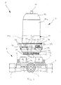
- All flush valves 1 belonging to the set are composed of two main components, namely a connector body 2 and a so-called "functional unit" 3.
- the connector body 2 which will be described in more detail below, is the same for all members of the kit; the "functional unit" 3, however, is different for the different members of the set of concealed fittings.
- the detailed structure of both the terminal body 2 and the functional unit 3 is not of interest in the present context; it is described only to the extent necessary to understand the manner in which the functional unit 3 is attached to the connector body 2.
- the terminal body 2 has the basic shape of a relatively shallow shell, in the lower region four connecting pieces 4, 5, 6, 7 are introduced.
- the connecting pieces 4, 5, 6, 7 may be integral part of the connecting body 2, but also separately with the connecting body 2 to be connected parts. Shown is the Case of the one-piece
- the connecting pieces 4, 5, 6, 7 communicate via water-carrying channels with four substantially cylindrical, axially parallel connecting bores 46, 47, 48, 49, which are brought out of the bottom region of the connecting body 2 upwards (see Figure 9).
- a check valve is in each case seen; the valve spindles 8, 9, via which these shut-off valves can be actuated, can be seen in particular in FIGS. 1 and 2.
- each of these fastening ribs 10, 11 has the shape of a circular ring segment; between adjacent fastening ribs 10, 11, a gap 12 is provided in each case, as again in particular of Figure 1 can be seen.
- the fastening ribs 10, 11 In the cylindrical inner circumferential surface of the fastening ribs 10, 11 each have a circular arc-shaped groove 13 is formed.
- the fastening ribs 10, 11 with their groove 13 and the gap 12 lying between the fastening ribs 10, 11 are part of a bayonet closure with which the functional unit 3 can be fastened to the connector body 2 in the manner described below.
- the terminal body 2 is mounted at a relatively early stage of expansion of the building in a niche of the corresponding building wall at a corresponding depth.
- the four connecting pieces 4, 5, 6, 7 are connected to corresponding laid in the wall of the building house lines.
- the connecting pieces 4, 7, which associated with the above-mentioned shut-off valves are connected to the cold water and hot water domestic line, while the connecting pieces 5 and 6 are connected to those lines leading to a shower or a bath spout.
- the terminal body 2 initially remains alone in the niche of the building wall, which is closed during this time in a suitable manner. Only in the final stage of interior design, the builder must decide what type of concealed fitting 1 he wants. Then the respective correct functional unit 3 is selected from the available set and connected to the terminal body 2 in a manner described below.
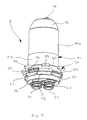
- the functional unit 3 has a substantially cylindrical adapter housing 14, in the upper region 14a of which a receiving space for a valve cartridge not shown is provided.
- a receiving space for a valve cartridge not shown is provided.
- the skilled artisan recognizes at the top of a hemispherical cap 15 extending out society 16, that in the present case is the valve cartridge of a single lever mixer.
- an O-ring seal 23 and 24 a In two axially spaced from each other annular grooves on the outer circumferential surface of the insertion pieces 19, 20, 21, 22 is in each case an O-ring seal 23 and 24 a.
- the upper O-ring seal 23 serves to seal the Einsteckstutzens 19, 20, 21, 22 against the adapter housing 14, while the respective lower O-ring seal 24 in the assembled state, the sealing of the Einsteckstutzens 19, 20, 21, 22 against the lateral surface of the Receiving opening 46, 47, 48, 49 in the connecting body 2 is used.
- the receiving space in the upper region 14a of the adapter housing 14 is substantially cylindrical and has a bottom surface into which three of the above-mentioned water-carrying channels open , Two of these water-conducting channels lead directly to those Einsteckstutzen 19, 22, which are introduced in the assembled functional part 3 in those receiving openings 46, 48 of the connector body 2, which communicate with the cold water or hot water house.
- the valve cartridge is supplied with hot and cold water via these channels.
- a third, opening into the bottom surface of the receiving space and not shown in the drawing channel leads to a provided in the lower portion 14b of the adapter housing 14 switching device, which is also not shown. Turn from the switching device run two channels to the spigot 20 and 21, which are introduced at mounted flush-mounted fitting 1 in those connection openings 47, 49 of the terminal body 2, which communicate with the bath spout or the shower.
- the arrangement is thus that, that the functional part 3 can be inserted in advance with its Einsteckstutzen 19, 20, 21, 22 in the connector body 2, whereby the necessary water connections between the laid in the building wall lines and the valve cartridge in the functional unit 3 are made.
- the bayonet ring 31 has a hollow cylindrical main portion 32, at the upper edge of a plurality of radially projecting projections 33 are formed at uniform angular intervals.
- the projections 33 serve, as will be described below, as starting points for the fingers of the installer during rotation of the bayonet ring 31st
- the arc length of the bayonet claws 34 is slightly smaller than the arc length of the gaps 12 between the fixing ribs 10, 11 of the terminal body 2; the arc length of the gaps 35 between adjacent bayonet claws 34 of the bayonet ring 31 is slightly larger than the arc length of the fastening ribs 10, 11 of the terminal body. 2
- three resilient latching lugs 36 are formed on the inner circumferential surface of the main region 32 of the bayonet ring 31 at an angular distance of 120 °.
- the locking lugs 36 are integrally connected in their lower region with the main portion 32 of the bayonet ring 31 and at its upper, free end, which can be elastically pressed radially outwardly provided with a radially inwardly pointing locking rib 37 (see Figure 6).
- the outer diameter of the lower portion 14b of the adapter housing 14 above the projections 25, 26, 27, 28 coincides with the inner diameter of the main portion 32 of the bayonet ring 31.
- the lateral surface of the region 14b is provided with a circumferential annular groove 38 (see FIG.
- the bayonet ring 1 can therefore be attached to the adapter housing 14 so that it is slipped over the adapter housing 14 from above. If he passes over the larger diameter in the lower portion 14b of the adapter housing 14, the locking lugs 36 are pressed elastically outwardly due to the radially inwardly projecting locking ribs 37. Reaching the locking ribs 37, the axial height of the annular groove 38 in the adapter housing 14, they can engage in this under relaxation.
- the bayonet ring 31 is then attached to the latter rotatable about the axis of the adapter housing 14.
- a spring arm 39 is formed, which extends substantially in the circumferential direction.
- end of the spring arm 39 is integrally connected to the main portion 32 of the bayonet ring 31, while at its free, in Figures 6 and 7, the left end has a downwardly projecting, integrally molded locking pin 40 .
- a wedge block 41 is integrally formed, which extends with relaxed spring arm 39 in an opening 42 on the underside of one of the projections 33 partially hineinerstreckt from the bottom but still has a certain distance.
- annular collar 43 of the adapter housing 14 is located between two projections 25, 26 an axially parallel bore 44, whose diameter is slightly larger than the diameter the locking pin 40 of the bayonet ring 31 is.
- the locking pin 40 can engage in the bore 44 in such a rotational position of the bayonet ring 1, in which the bayonet claws 34 above the projections 25, 26, 27, 28 of the adapter housing 14 and the gaps between these projections 25, 26, 27, 28 with the gaps between the bayonet claws 34 are aligned.
- leg spring 45 In the space between the inner circumferential surface of the bayonet claws 34 and the lateral surface of the lower portion 14b of the adapter housing 14 serving as a torsion spring leg spring 45 is inserted.
- This leg spring 45 can be seen in particular in Figures 7 and 8.
- An axially parallel bent out end of this leg spring 45 is hooked into an axially parallel bore at the top of the annular collar 43, the other, axially parallel bent end of the leg spring 45 in a corresponding bore of the bayonet ring 31.
- the arrangement is such that the leg spring 45 in the assembled state seeks to rotate the bayonet ring 31 to a position in which the bayonet claws 34, unlike in Figures 2, 3 and 7, over the gaps between adjacent projections 25, 26, 27, 28th stand of the adapter housing 14.
- the functional unit 3 is now operatively connected to the terminal housing 2 and only needs to be supplemented in the usual way by a rosette covering the installation niche and provided with the operating handle.
Landscapes
- Health & Medical Sciences (AREA)
- Life Sciences & Earth Sciences (AREA)
- Engineering & Computer Science (AREA)
- Hydrology & Water Resources (AREA)
- Public Health (AREA)
- Water Supply & Treatment (AREA)
- Quick-Acting Or Multi-Walled Pipe Joints (AREA)
- Orthopedics, Nursing, And Contraception (AREA)
- Absorbent Articles And Supports Therefor (AREA)
- Connector Housings Or Holding Contact Members (AREA)
- Domestic Plumbing Installations (AREA)
Applications Claiming Priority (1)
| Application Number | Priority Date | Filing Date | Title |
|---|---|---|---|
| DE102004034150A DE102004034150B4 (de) | 2004-07-15 | 2004-07-15 | Sanitäre Unterputzarmatur |
Publications (3)
| Publication Number | Publication Date |
|---|---|
| EP1616998A2 true EP1616998A2 (fr) | 2006-01-18 |
| EP1616998A3 EP1616998A3 (fr) | 2008-06-04 |
| EP1616998B1 EP1616998B1 (fr) | 2009-02-18 |
Family
ID=34937564
Family Applications (1)
| Application Number | Title | Priority Date | Filing Date |
|---|---|---|---|
| EP05013298A Not-in-force EP1616998B1 (fr) | 2004-07-15 | 2005-06-21 | Armature sanitaire mural |
Country Status (3)
| Country | Link |
|---|---|
| EP (1) | EP1616998B1 (fr) |
| AT (1) | ATE423238T1 (fr) |
| DE (2) | DE102004034150B4 (fr) |
Cited By (4)
| Publication number | Priority date | Publication date | Assignee | Title |
|---|---|---|---|---|
| EP1657366A2 (fr) * | 2004-11-12 | 2006-05-17 | Hansa Metallwerke Ag | Armature sanitaire murale |
| DE102014014744A1 (de) * | 2014-10-09 | 2016-04-14 | Grohe Ag | Sanitärarmatur mit einer Halterung für eine Kartusche |
| WO2016133475A3 (fr) * | 2015-02-18 | 2016-10-13 | Eczacibaşi Yapi Gereçleri̇ Sanayi̇ Ve Ticaret Anoni̇m Şi̇rketi̇ | Mécanisme pour le placement de tous types de groupes montés en surface sur tous types de groupes encastrés dans des appareils intégrés et appareil comprenant ledit mécanisme |
| IT201800007171A1 (it) * | 2018-07-13 | 2020-01-13 | Raccordo di distribuzione di fluido incassato a muro per rubinetto miscelatore di fluido |
Families Citing this family (3)
| Publication number | Priority date | Publication date | Assignee | Title |
|---|---|---|---|---|
| DE102007010965B3 (de) * | 2007-03-05 | 2008-10-09 | Hansa Metallwerke Ag | Sanitärarmatur |
| DE102009012837B3 (de) * | 2009-03-04 | 2010-06-10 | Hansgrohe Ag | Verbindungsanordnung für Sanitärarmaturen |
| DE102019100676A1 (de) * | 2019-01-11 | 2020-07-16 | Grohe Ag | Unterputz-Baugruppe für eine Sanitärarmatur |
Citations (3)
| Publication number | Priority date | Publication date | Assignee | Title |
|---|---|---|---|---|
| DE3723828A1 (de) * | 1987-07-18 | 1989-01-26 | Grohe Armaturen Friedrich | Anschlussvorrichtung fuer mischarmaturen und verfahren zum anschluss der armatur |
| EP0389810A1 (fr) * | 1989-03-09 | 1990-10-03 | Friedrich Grohe Aktiengesellschaft | Dispositif de raccordement pour robinets mélangeurs |
| US20030192116A1 (en) * | 2002-04-12 | 2003-10-16 | Burger Terry L. | Tub and shower valve |
Family Cites Families (4)
| Publication number | Priority date | Publication date | Assignee | Title |
|---|---|---|---|---|
| DE3519763C2 (de) * | 1985-06-01 | 1994-01-05 | Grohe Armaturen Friedrich | Unterputzanschlußstück |
| DE19806634A1 (de) * | 1998-02-18 | 1999-08-19 | Grohe Armaturen Friedrich | Befestigungsvorrichtung für Wasserarmaturen |
| DE20102175U1 (de) * | 2000-03-21 | 2001-06-13 | Geberit Technik Ag | Sanitär-Spülarmatur |
| DE10161144B4 (de) * | 2001-12-12 | 2004-04-15 | Reinert. Ritz Gmbh | Zugfeste Rohrverbindung |
-
2004
- 2004-07-15 DE DE102004034150A patent/DE102004034150B4/de not_active Expired - Fee Related
-
2005
- 2005-06-21 EP EP05013298A patent/EP1616998B1/fr not_active Not-in-force
- 2005-06-21 AT AT05013298T patent/ATE423238T1/de active
- 2005-06-21 DE DE502005006635T patent/DE502005006635D1/de active Active
Patent Citations (3)
| Publication number | Priority date | Publication date | Assignee | Title |
|---|---|---|---|---|
| DE3723828A1 (de) * | 1987-07-18 | 1989-01-26 | Grohe Armaturen Friedrich | Anschlussvorrichtung fuer mischarmaturen und verfahren zum anschluss der armatur |
| EP0389810A1 (fr) * | 1989-03-09 | 1990-10-03 | Friedrich Grohe Aktiengesellschaft | Dispositif de raccordement pour robinets mélangeurs |
| US20030192116A1 (en) * | 2002-04-12 | 2003-10-16 | Burger Terry L. | Tub and shower valve |
Cited By (5)
| Publication number | Priority date | Publication date | Assignee | Title |
|---|---|---|---|---|
| EP1657366A2 (fr) * | 2004-11-12 | 2006-05-17 | Hansa Metallwerke Ag | Armature sanitaire murale |
| EP1657366A3 (fr) * | 2004-11-12 | 2006-09-20 | Hansa Metallwerke Ag | Armature sanitaire murale |
| DE102014014744A1 (de) * | 2014-10-09 | 2016-04-14 | Grohe Ag | Sanitärarmatur mit einer Halterung für eine Kartusche |
| WO2016133475A3 (fr) * | 2015-02-18 | 2016-10-13 | Eczacibaşi Yapi Gereçleri̇ Sanayi̇ Ve Ticaret Anoni̇m Şi̇rketi̇ | Mécanisme pour le placement de tous types de groupes montés en surface sur tous types de groupes encastrés dans des appareils intégrés et appareil comprenant ledit mécanisme |
| IT201800007171A1 (it) * | 2018-07-13 | 2020-01-13 | Raccordo di distribuzione di fluido incassato a muro per rubinetto miscelatore di fluido |
Also Published As
| Publication number | Publication date |
|---|---|
| DE102004034150A1 (de) | 2006-02-09 |
| EP1616998A3 (fr) | 2008-06-04 |
| DE502005006635D1 (de) | 2009-04-02 |
| DE102004034150B4 (de) | 2008-10-09 |
| ATE423238T1 (de) | 2009-03-15 |
| EP1616998B1 (fr) | 2009-02-18 |
Similar Documents
| Publication | Publication Date | Title |
|---|---|---|
| EP1616998B1 (fr) | Armature sanitaire mural | |
| EP2101002B1 (fr) | Boîtier d'encastrement destiné à l'encastrement variable d'armatures sanitaires | |
| WO2006018274A1 (fr) | Appareil de plomberie dissimule | |
| EP1657366B1 (fr) | Armature sanitaire murale | |
| EP0733839A1 (fr) | Mitigeur avec un levier | |
| DE102007009409B4 (de) | Armatur mit Schwenkauslauf | |
| DE102015101695A1 (de) | Wandarmatur und Verfahren zu deren Befestigung | |
| EP1809822B1 (fr) | Robinetterie sanitaire encastree | |
| DE102015219175B4 (de) | Anschlussrohrstutzen für eine Sanitärarmatur | |
| DE102014008570A1 (de) | Sanitäre Unterputzarmatur | |
| DE4314101A1 (de) | Armatur mit Bajonettverschluß | |
| DE102008023671B4 (de) | Wandhalterung | |
| DE10358119B4 (de) | Einbauvorrichtung für Sanitärarmaturen | |
| DE19902397C1 (de) | Sanitärarmatur, insbesondere Waschtischarmatur | |
| DE102013016103B4 (de) | Anschlusskörper für eine sanitare Unterputzarmatur | |
| EP1438529B1 (fr) | Connecteur de gaz | |
| EP3914783A1 (fr) | Pièce de raccordement de robinetterie | |
| EP1128108B1 (fr) | Dispositif de raccordement sanitaire | |
| DE10243304B4 (de) | Schwenkauslauf für Sanitärarmaturen | |
| EP4303371A1 (fr) | Robinetterie sanitaire pourvue d'élément de verrouillage | |
| EP3122949B1 (fr) | Dispositif d'installation encastré pour des mitigeurs à levier unique | |
| DE4125569A1 (de) | Anschlussvorrichtung fuer eine an einer gebaeudewand angeordneten mischbatterie | |
| DE10316417B4 (de) | Sanitärarmatur | |
| DE102005061112A1 (de) | Hülsrohrglocke mit Adapter | |
| DE102007022788A1 (de) | Hülsrohrglocke mit Adapter II |
Legal Events
| Date | Code | Title | Description |
|---|---|---|---|
| PUAI | Public reference made under article 153(3) epc to a published international application that has entered the european phase |
Free format text: ORIGINAL CODE: 0009012 |
|
| AK | Designated contracting states |
Kind code of ref document: A2 Designated state(s): AT BE BG CH CY CZ DE DK EE ES FI FR GB GR HU IE IS IT LI LT LU MC NL PL PT RO SE SI SK TR |
|
| AX | Request for extension of the european patent |
Extension state: AL BA HR LV MK YU |
|
| PUAL | Search report despatched |
Free format text: ORIGINAL CODE: 0009013 |
|
| AK | Designated contracting states |
Kind code of ref document: A3 Designated state(s): AT BE BG CH CY CZ DE DK EE ES FI FR GB GR HU IE IS IT LI LT LU MC NL PL PT RO SE SI SK TR |
|
| AX | Request for extension of the european patent |
Extension state: AL BA HR LV MK YU |
|
| RIC1 | Information provided on ipc code assigned before grant |
Ipc: E03C 1/04 20060101AFI20050713BHEP Ipc: E03C 1/02 20060101ALI20080425BHEP |
|
| GRAP | Despatch of communication of intention to grant a patent |
Free format text: ORIGINAL CODE: EPIDOSNIGR1 |
|
| 17P | Request for examination filed |
Effective date: 20080719 |
|
| GRAS | Grant fee paid |
Free format text: ORIGINAL CODE: EPIDOSNIGR3 |
|
| GRAA | (expected) grant |
Free format text: ORIGINAL CODE: 0009210 |
|
| AKX | Designation fees paid |
Designated state(s): AT BE BG CH CY CZ DE DK EE ES FI FR GB GR HU IE IS IT LI LT LU MC NL PL PT RO SE SI SK TR |
|
| AK | Designated contracting states |
Kind code of ref document: B1 Designated state(s): AT BE BG CH CY CZ DE DK EE ES FI FR GB GR HU IE IS IT LI LT LU MC NL PL PT RO SE SI SK TR |
|
| REG | Reference to a national code |
Ref country code: GB Ref legal event code: FG4D Free format text: NOT ENGLISH |
|
| REG | Reference to a national code |
Ref country code: CH Ref legal event code: EP |
|
| REG | Reference to a national code |
Ref country code: CH Ref legal event code: NV Representative=s name: FREI PATENTANWALTSBUERO AG |
|
| REG | Reference to a national code |
Ref country code: IE Ref legal event code: FG4D Free format text: LANGUAGE OF EP DOCUMENT: GERMAN |
|
| REF | Corresponds to: |
Ref document number: 502005006635 Country of ref document: DE Date of ref document: 20090402 Kind code of ref document: P |
|
| PG25 | Lapsed in a contracting state [announced via postgrant information from national office to epo] |
Ref country code: ES Free format text: LAPSE BECAUSE OF FAILURE TO SUBMIT A TRANSLATION OF THE DESCRIPTION OR TO PAY THE FEE WITHIN THE PRESCRIBED TIME-LIMIT Effective date: 20090529 Ref country code: LT Free format text: LAPSE BECAUSE OF FAILURE TO SUBMIT A TRANSLATION OF THE DESCRIPTION OR TO PAY THE FEE WITHIN THE PRESCRIBED TIME-LIMIT Effective date: 20090218 Ref country code: FI Free format text: LAPSE BECAUSE OF FAILURE TO SUBMIT A TRANSLATION OF THE DESCRIPTION OR TO PAY THE FEE WITHIN THE PRESCRIBED TIME-LIMIT Effective date: 20090218 Ref country code: SI Free format text: LAPSE BECAUSE OF FAILURE TO SUBMIT A TRANSLATION OF THE DESCRIPTION OR TO PAY THE FEE WITHIN THE PRESCRIBED TIME-LIMIT Effective date: 20090218 Ref country code: NL Free format text: LAPSE BECAUSE OF FAILURE TO SUBMIT A TRANSLATION OF THE DESCRIPTION OR TO PAY THE FEE WITHIN THE PRESCRIBED TIME-LIMIT Effective date: 20090218 |
|
| NLV1 | Nl: lapsed or annulled due to failure to fulfill the requirements of art. 29p and 29m of the patents act | ||
| PG25 | Lapsed in a contracting state [announced via postgrant information from national office to epo] |
Ref country code: PL Free format text: LAPSE BECAUSE OF FAILURE TO SUBMIT A TRANSLATION OF THE DESCRIPTION OR TO PAY THE FEE WITHIN THE PRESCRIBED TIME-LIMIT Effective date: 20090218 Ref country code: SE Free format text: LAPSE BECAUSE OF FAILURE TO SUBMIT A TRANSLATION OF THE DESCRIPTION OR TO PAY THE FEE WITHIN THE PRESCRIBED TIME-LIMIT Effective date: 20090518 Ref country code: IS Free format text: LAPSE BECAUSE OF FAILURE TO SUBMIT A TRANSLATION OF THE DESCRIPTION OR TO PAY THE FEE WITHIN THE PRESCRIBED TIME-LIMIT Effective date: 20090618 |
|
| REG | Reference to a national code |
Ref country code: IE Ref legal event code: FD4D |
|
| PG25 | Lapsed in a contracting state [announced via postgrant information from national office to epo] |
Ref country code: PT Free format text: LAPSE BECAUSE OF FAILURE TO SUBMIT A TRANSLATION OF THE DESCRIPTION OR TO PAY THE FEE WITHIN THE PRESCRIBED TIME-LIMIT Effective date: 20090727 Ref country code: IE Free format text: LAPSE BECAUSE OF FAILURE TO SUBMIT A TRANSLATION OF THE DESCRIPTION OR TO PAY THE FEE WITHIN THE PRESCRIBED TIME-LIMIT Effective date: 20090218 Ref country code: DK Free format text: LAPSE BECAUSE OF FAILURE TO SUBMIT A TRANSLATION OF THE DESCRIPTION OR TO PAY THE FEE WITHIN THE PRESCRIBED TIME-LIMIT Effective date: 20090218 Ref country code: CZ Free format text: LAPSE BECAUSE OF FAILURE TO SUBMIT A TRANSLATION OF THE DESCRIPTION OR TO PAY THE FEE WITHIN THE PRESCRIBED TIME-LIMIT Effective date: 20090218 Ref country code: EE Free format text: LAPSE BECAUSE OF FAILURE TO SUBMIT A TRANSLATION OF THE DESCRIPTION OR TO PAY THE FEE WITHIN THE PRESCRIBED TIME-LIMIT Effective date: 20090218 |
|
| PG25 | Lapsed in a contracting state [announced via postgrant information from national office to epo] |
Ref country code: SK Free format text: LAPSE BECAUSE OF FAILURE TO SUBMIT A TRANSLATION OF THE DESCRIPTION OR TO PAY THE FEE WITHIN THE PRESCRIBED TIME-LIMIT Effective date: 20090218 Ref country code: RO Free format text: LAPSE BECAUSE OF FAILURE TO SUBMIT A TRANSLATION OF THE DESCRIPTION OR TO PAY THE FEE WITHIN THE PRESCRIBED TIME-LIMIT Effective date: 20090218 |
|
| PLBE | No opposition filed within time limit |
Free format text: ORIGINAL CODE: 0009261 |
|
| STAA | Information on the status of an ep patent application or granted ep patent |
Free format text: STATUS: NO OPPOSITION FILED WITHIN TIME LIMIT |
|
| BERE | Be: lapsed |
Owner name: HANSA METALLWERKE A.G. Effective date: 20090630 |
|
| 26N | No opposition filed |
Effective date: 20091119 |
|
| PG25 | Lapsed in a contracting state [announced via postgrant information from national office to epo] |
Ref country code: MC Free format text: LAPSE BECAUSE OF NON-PAYMENT OF DUE FEES Effective date: 20090630 Ref country code: BG Free format text: LAPSE BECAUSE OF FAILURE TO SUBMIT A TRANSLATION OF THE DESCRIPTION OR TO PAY THE FEE WITHIN THE PRESCRIBED TIME-LIMIT Effective date: 20090518 |
|
| GBPC | Gb: european patent ceased through non-payment of renewal fee |
Effective date: 20090621 |
|
| REG | Reference to a national code |
Ref country code: FR Ref legal event code: ST Effective date: 20100226 |
|
| PG25 | Lapsed in a contracting state [announced via postgrant information from national office to epo] |
Ref country code: FR Free format text: LAPSE BECAUSE OF NON-PAYMENT OF DUE FEES Effective date: 20090630 |
|
| PG25 | Lapsed in a contracting state [announced via postgrant information from national office to epo] |
Ref country code: GB Free format text: LAPSE BECAUSE OF NON-PAYMENT OF DUE FEES Effective date: 20090621 |
|
| PG25 | Lapsed in a contracting state [announced via postgrant information from national office to epo] |
Ref country code: BE Free format text: LAPSE BECAUSE OF NON-PAYMENT OF DUE FEES Effective date: 20090630 |
|
| PG25 | Lapsed in a contracting state [announced via postgrant information from national office to epo] |
Ref country code: GR Free format text: LAPSE BECAUSE OF FAILURE TO SUBMIT A TRANSLATION OF THE DESCRIPTION OR TO PAY THE FEE WITHIN THE PRESCRIBED TIME-LIMIT Effective date: 20090519 |
|
| PG25 | Lapsed in a contracting state [announced via postgrant information from national office to epo] |
Ref country code: IT Free format text: LAPSE BECAUSE OF FAILURE TO SUBMIT A TRANSLATION OF THE DESCRIPTION OR TO PAY THE FEE WITHIN THE PRESCRIBED TIME-LIMIT Effective date: 20090218 |
|
| PG25 | Lapsed in a contracting state [announced via postgrant information from national office to epo] |
Ref country code: LU Free format text: LAPSE BECAUSE OF NON-PAYMENT OF DUE FEES Effective date: 20090621 |
|
| PG25 | Lapsed in a contracting state [announced via postgrant information from national office to epo] |
Ref country code: HU Free format text: LAPSE BECAUSE OF FAILURE TO SUBMIT A TRANSLATION OF THE DESCRIPTION OR TO PAY THE FEE WITHIN THE PRESCRIBED TIME-LIMIT Effective date: 20090819 |
|
| PG25 | Lapsed in a contracting state [announced via postgrant information from national office to epo] |
Ref country code: TR Free format text: LAPSE BECAUSE OF FAILURE TO SUBMIT A TRANSLATION OF THE DESCRIPTION OR TO PAY THE FEE WITHIN THE PRESCRIBED TIME-LIMIT Effective date: 20090218 |
|
| PG25 | Lapsed in a contracting state [announced via postgrant information from national office to epo] |
Ref country code: CY Free format text: LAPSE BECAUSE OF FAILURE TO SUBMIT A TRANSLATION OF THE DESCRIPTION OR TO PAY THE FEE WITHIN THE PRESCRIBED TIME-LIMIT Effective date: 20090218 |
|
| PGFP | Annual fee paid to national office [announced via postgrant information from national office to epo] |
Ref country code: CH Payment date: 20160620 Year of fee payment: 12 |
|
| REG | Reference to a national code |
Ref country code: CH Ref legal event code: PL |
|
| PG25 | Lapsed in a contracting state [announced via postgrant information from national office to epo] |
Ref country code: LI Free format text: LAPSE BECAUSE OF NON-PAYMENT OF DUE FEES Effective date: 20170630 Ref country code: CH Free format text: LAPSE BECAUSE OF NON-PAYMENT OF DUE FEES Effective date: 20170630 |
|
| PGFP | Annual fee paid to national office [announced via postgrant information from national office to epo] |
Ref country code: DE Payment date: 20180625 Year of fee payment: 14 |
|
| PGFP | Annual fee paid to national office [announced via postgrant information from national office to epo] |
Ref country code: AT Payment date: 20180621 Year of fee payment: 14 |
|
| REG | Reference to a national code |
Ref country code: DE Ref legal event code: R119 Ref document number: 502005006635 Country of ref document: DE |
|
| REG | Reference to a national code |
Ref country code: AT Ref legal event code: MM01 Ref document number: 423238 Country of ref document: AT Kind code of ref document: T Effective date: 20190621 |
|
| PG25 | Lapsed in a contracting state [announced via postgrant information from national office to epo] |
Ref country code: AT Free format text: LAPSE BECAUSE OF NON-PAYMENT OF DUE FEES Effective date: 20190621 Ref country code: DE Free format text: LAPSE BECAUSE OF NON-PAYMENT OF DUE FEES Effective date: 20200101 |