EP1613824B1 - Scharnier - Google Patents
Scharnier Download PDFInfo
- Publication number
- EP1613824B1 EP1613824B1 EP04726701A EP04726701A EP1613824B1 EP 1613824 B1 EP1613824 B1 EP 1613824B1 EP 04726701 A EP04726701 A EP 04726701A EP 04726701 A EP04726701 A EP 04726701A EP 1613824 B1 EP1613824 B1 EP 1613824B1
- Authority
- EP
- European Patent Office
- Prior art keywords
- hinge
- damper housing
- cup
- bore
- hinge according
- Prior art date
- Legal status (The legal status is an assumption and is not a legal conclusion. Google has not performed a legal analysis and makes no representation as to the accuracy of the status listed.)
- Expired - Lifetime
Links
- 238000013016 damping Methods 0.000 claims description 7
- 239000012530 fluid Substances 0.000 claims description 3
- 238000002347 injection Methods 0.000 claims 1
- 239000007924 injection Substances 0.000 claims 1
- 238000004873 anchoring Methods 0.000 abstract 1
- 238000010586 diagram Methods 0.000 description 10
- 230000006835 compression Effects 0.000 description 2
- 238000007906 compression Methods 0.000 description 2
- 238000004519 manufacturing process Methods 0.000 description 1
- 230000007246 mechanism Effects 0.000 description 1
Images





Classifications
-
- E—FIXED CONSTRUCTIONS
- E05—LOCKS; KEYS; WINDOW OR DOOR FITTINGS; SAFES
- E05F—DEVICES FOR MOVING WINGS INTO OPEN OR CLOSED POSITION; CHECKS FOR WINGS; WING FITTINGS NOT OTHERWISE PROVIDED FOR, CONCERNED WITH THE FUNCTIONING OF THE WING
- E05F5/00—Braking devices, e.g. checks; Stops; Buffers
- E05F5/006—Braking devices, e.g. checks; Stops; Buffers for hinges having a cup-shaped fixing part, e.g. for attachment to cabinets or furniture
-
- E—FIXED CONSTRUCTIONS
- E05—LOCKS; KEYS; WINDOW OR DOOR FITTINGS; SAFES
- E05Y—INDEXING SCHEME ASSOCIATED WITH SUBCLASSES E05D AND E05F, RELATING TO CONSTRUCTION ELEMENTS, ELECTRIC CONTROL, POWER SUPPLY, POWER SIGNAL OR TRANSMISSION, USER INTERFACES, MOUNTING OR COUPLING, DETAILS, ACCESSORIES, AUXILIARY OPERATIONS NOT OTHERWISE PROVIDED FOR, APPLICATION THEREOF
- E05Y2201/00—Constructional elements; Accessories therefor
- E05Y2201/20—Brakes; Disengaging means; Holders; Stops; Valves; Accessories therefor
- E05Y2201/21—Brakes
-
- E—FIXED CONSTRUCTIONS
- E05—LOCKS; KEYS; WINDOW OR DOOR FITTINGS; SAFES
- E05Y—INDEXING SCHEME ASSOCIATED WITH SUBCLASSES E05D AND E05F, RELATING TO CONSTRUCTION ELEMENTS, ELECTRIC CONTROL, POWER SUPPLY, POWER SIGNAL OR TRANSMISSION, USER INTERFACES, MOUNTING OR COUPLING, DETAILS, ACCESSORIES, AUXILIARY OPERATIONS NOT OTHERWISE PROVIDED FOR, APPLICATION THEREOF
- E05Y2201/00—Constructional elements; Accessories therefor
- E05Y2201/20—Brakes; Disengaging means; Holders; Stops; Valves; Accessories therefor
- E05Y2201/252—Type of friction
- E05Y2201/254—Fluid or viscous friction
- E05Y2201/256—Fluid or viscous friction with pistons or vanes
-
- E—FIXED CONSTRUCTIONS
- E05—LOCKS; KEYS; WINDOW OR DOOR FITTINGS; SAFES
- E05Y—INDEXING SCHEME ASSOCIATED WITH SUBCLASSES E05D AND E05F, RELATING TO CONSTRUCTION ELEMENTS, ELECTRIC CONTROL, POWER SUPPLY, POWER SIGNAL OR TRANSMISSION, USER INTERFACES, MOUNTING OR COUPLING, DETAILS, ACCESSORIES, AUXILIARY OPERATIONS NOT OTHERWISE PROVIDED FOR, APPLICATION THEREOF
- E05Y2201/00—Constructional elements; Accessories therefor
- E05Y2201/20—Brakes; Disengaging means; Holders; Stops; Valves; Accessories therefor
- E05Y2201/262—Type of motion, e.g. braking
- E05Y2201/266—Type of motion, e.g. braking rotary
-
- E—FIXED CONSTRUCTIONS
- E05—LOCKS; KEYS; WINDOW OR DOOR FITTINGS; SAFES
- E05Y—INDEXING SCHEME ASSOCIATED WITH SUBCLASSES E05D AND E05F, RELATING TO CONSTRUCTION ELEMENTS, ELECTRIC CONTROL, POWER SUPPLY, POWER SIGNAL OR TRANSMISSION, USER INTERFACES, MOUNTING OR COUPLING, DETAILS, ACCESSORIES, AUXILIARY OPERATIONS NOT OTHERWISE PROVIDED FOR, APPLICATION THEREOF
- E05Y2201/00—Constructional elements; Accessories therefor
- E05Y2201/60—Suspension or transmission members; Accessories therefor
- E05Y2201/622—Suspension or transmission members elements
- E05Y2201/638—Cams; Ramps
-
- E—FIXED CONSTRUCTIONS
- E05—LOCKS; KEYS; WINDOW OR DOOR FITTINGS; SAFES
- E05Y—INDEXING SCHEME ASSOCIATED WITH SUBCLASSES E05D AND E05F, RELATING TO CONSTRUCTION ELEMENTS, ELECTRIC CONTROL, POWER SUPPLY, POWER SIGNAL OR TRANSMISSION, USER INTERFACES, MOUNTING OR COUPLING, DETAILS, ACCESSORIES, AUXILIARY OPERATIONS NOT OTHERWISE PROVIDED FOR, APPLICATION THEREOF
- E05Y2600/00—Mounting or coupling arrangements for elements provided for in this subclass
- E05Y2600/40—Mounting location; Visibility of the elements
- E05Y2600/46—Mounting location; Visibility of the elements in or on the wing
-
- E—FIXED CONSTRUCTIONS
- E05—LOCKS; KEYS; WINDOW OR DOOR FITTINGS; SAFES
- E05Y—INDEXING SCHEME ASSOCIATED WITH SUBCLASSES E05D AND E05F, RELATING TO CONSTRUCTION ELEMENTS, ELECTRIC CONTROL, POWER SUPPLY, POWER SIGNAL OR TRANSMISSION, USER INTERFACES, MOUNTING OR COUPLING, DETAILS, ACCESSORIES, AUXILIARY OPERATIONS NOT OTHERWISE PROVIDED FOR, APPLICATION THEREOF
- E05Y2900/00—Application of doors, windows, wings or fittings thereof
- E05Y2900/20—Application of doors, windows, wings or fittings thereof for furniture, e.g. cabinets
Definitions
- the invention relates to a hinge with a hinge cup, which is insertable into a bore in a furniture part, with a damper housing attached to the hinge cup.
- Hinges which are provided with a damper, which slows down when closing the furniture door, are from the EP 1 199 433 A2 , the Austrian utility model AT 005 477 U1 and the German utility model DE 202 05 905 U known.
- DE 20115250 U discloses all features of the preamble of claim 1.
- the object of the invention is to provide a hinge with a damper, wherein the damper is universally applicable.
- the damper housing is arranged in the inserted into the bore of the furniture part hinge cup entirely outside the bore.
- a further embodiment of the invention provides that the hinge cup has a voltage applied to the furniture door flange and that the damper housing is anchored to the flange of the hinge cup.
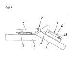
- the damper 1 is anchored on the hinge cup 3 of a hinge 2.
- the hinge cup 3 is inserted into a bore of the furniture door 7 and connected via a hinge lever 5 with a hinge arm 4, which is anchored to a base plate 6.
- the base plate 6 is fixed to a cabinet side wall 8, for example screwed to this.
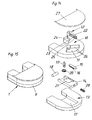
- the damper 1 is designed as a rotary damper with a rotary piston 12. It has a two-part damper housing 9. In a housing part 10, a cylinder chamber 11 is formed, in which the rotary piston 12 of the damper 1 is arranged and in the second housing part 13 supports a slide 14, which forms the actuating part.
- the slider 14 is provided with an insert part 15 on which a rack profile 16 is formed.
- the rack profile 16 could also be formed directly on the slide 14.
- the insert 15 has purely manufacturing advantages.
- the slider 14 is slidably mounted in a recess 17 of the housing part 13 and is acted upon by a compression spring 28. At its protruding from the damper housing 9 end of the slider 14 is provided with a roller body 18, which rolls when closing the furniture door 7 on the hinge 4.
- the rotary piston 12 rests on an axis 19. At the other end of the axis 19 is a pinion 20 which is received in the mounting position in a recess 21 of the slider 14 and meshes with the rack profile 16 of the insert part 15.
- the vane 22 of the rotary piston 12 has a valve which is formed by an opening 23 in the wing 22 and a leaf spring 24.
- the leaf spring 24 seals the opening 23 in the wing 22, and the damping fluid is forced through the gap between the tip 25 of the blade 22 and the wall 26 of the damper housing 9, resulting in the desired damping effect .
- the rotary piston 2 is rotated in the opposite direction, wherein the leaf spring 24 opens and the opening 23 releases, so that the damping fluid can flow through the opening 23.
- the compression spring 28 pushes the slider 14 back into the ready position.
- the damper housing 9 or the housing part 10 is provided with a cover cap 27.
- the hinge cup 3 has a flange 29 with an edge 30. In the edge 30 29 recesses 31 are formed on opposite sides of the flange.
- the damper housing 9 of the rotary damper 1 has molded sprung hooks 32, which engage with mounted rotary damper 1 in the recesses 31 below the flange 29.
- the rotary damper 1 can thus be mounted without tools on the hinge cup 3 by simply being pressed onto the flange 29 thereof.
- the resilient hooks 32 are formed so that the damper housing 9 is also detachable from the flange 29. The dismantling of the damper housing 9 from the flange 29 can be done without tools.
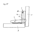
- hinge arms 4 may have different shapes, for example, there are also cranked hinge arms 4, can be fastened on the hinge arm 4, a top piece 17, on which the control surface 21 for the actuating part in the embodiment, the slider 14 is formed.
- the actuating member presses with its free end on the control surface 21.
- the control surface 21st describes a curved path that is adapted to the respective requirements.
- the control surface 21 may be inclined in opposite directions, concave, convex but also straight and oblique. This enables a targeted influencing of the closing characteristic for different hinge types and different closing mechanisms.
- the top piece is provided, for example, with pins 33 and the hinge arm 4 with holes 34, so that the top piece 17 can be easily pressed on the hinge arm 4 as needed.
Landscapes
- Hinges (AREA)
- Vehicle Step Arrangements And Article Storage (AREA)
- Passenger Equipment (AREA)
- Table Devices Or Equipment (AREA)
Description
- Die Erfindung bezieht sich auf ein Scharnier mit einem Scharniertopf, der in eine Bohrung in einem Möbelteil einsetzbar ist, mit einem am Scharniertopf befestigten Dämpfergehäuse.
- Scharniere, die mit einem Dämpfer versehen sind, der beim Schließen der Möbeltüre diese abbremst, sind aus der
EP 1 199 433 A2 , dem österreichischen GebrauchsmusterAT 005 477 U1 DE 202 05 905 U bekannt.DE 20115250 U offenbart alle Merkmale des Oberbegriffs des Anspruchs 1. Aufgabe der Erfindung ist es, ein Scharnier mit einem Dämpfer zu schaffen, wobei der Dämpfer universeller einsetzbar ist. - Die erfindungsgemäße Aufgabe wird durch die Merkmale des Anspruchs 1 gelöst.
- Vorteilhaft ist vorgesehen, dass das Dämpfergehäuse bei in die Bohrung des Möbelteiles eingesetztem Scharniertopf zur Gänze außerhalb der Bohrung angeordnet ist.
- Ein weiteres Ausführungsbeispiel der Erfindung sieht vor, dass der Scharniertopf einen an der Möbeltüre anliegenden Flansch aufweist und dass das Dämpfergehäuse am Flansch des Scharniertopfes verankert ist.
- Nachfolgend wird ein Ausführungsbeispiel der Erfindung anhand der Figuren der beiliegenden Zeichnungen beschrieben. Es zeigen:
- Die
Fig. 1 eine Seitenansicht einer Ausführungsform eines mit einem Dämpfer versehenen erfindungsgemäßen Scharniers, wobei Teile einer Korpuswand und der Möbeltüre gezeigt sind, - die
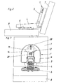
Fig. 2 eine Seitenansicht einer Ausführungsform eines erfindungsgemäßen Scharniers mit einem Dämpfer, wobei das Scharnier am Anfang des Dämpfungsweges gezeigt ist, - die
Fig. 3 eine Draufsicht auf ein Scharnier gemäß derFig. 2 , -
Fig. 4 eine Seitenansicht einer Ausführungsform eines erfindungsgemäßen Scharniers mit einem Dämpfer, wobei das Scharnier im mittleren Dämpfungsbereich gezeigt ist, - die
Fig. 5 eine Draufsicht auf ein Scharnier gemäß derFig. 4 , - die
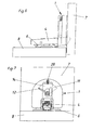
Fig. 6 eine Seitenansicht einer Ausführungsform eines erfindungsgemäßen Scharniers mit einem Dämpfer, wobei das Scharnier in der geschlossenen Stellung gezeigt ist, - die
Fig. 7 eine Draufsicht auf ein Scharnier gemäß derFig. 6 , - die
Fig. 8 ein Schaubild eines auf einen Scharniertopf befestigten Dämpfers von oben gesehen, - die
Fig. 9 ein auseinandergezogenes Schaubild einer Ausführungsform eines erfindungsgemäßen Dämpfers und eines Scharniertopfes, - die
Fig. 10 ein auseinandergezogenes Schaubild einer Ausführungsform eines erfindungsgemäßen Dämpfers und eines Scharniertopfes, wobei die Teile in Bezug auf dieFig. 8 um 180° gedreht sind, - die
Fig. 11 ein Schaubild einer Ausführungsform eines Scharniertopfes mit dem Dämpfer, - die
Fig. 12 ein Schaubild einer Ausführungsform eines erfindungsgemäßen Dämpfers, - die
Fig. 13 ein auseinandhergezogenes Schaubild einer Ausführungsform eines erfindungsgemäßen Dämpfers, - die
Fig. 14 ein auseinandergezogenes Schaubild einer Ausführungsform eines erfindungsgemäßen Dämpfers, wobei die Teile in Bezug auf dieFig. 13 um 180° gedreht gezeichnet sind, - die
Fig. 15 ein weiteres Schaubild einer Ausführungsform eines erfindungsgemäßen Dämpfers, - die
Fig. 16 ein Schaubild eines Scharnierarmes mit einem Aufsatzstück, - die
Fig. 17 ein Schaubild eines Scharnierarmes, der zur Aufnahme eines Aufsatzstückes geeignet ist, - die
Fig. 18 bis 20 Seitenansichten eines Aufsatzstückes, - die
Fig. 21 zeigt eine Seitenansicht eines Scharniers mit aufgesetztem Aufsatzstück in der Offenstellung, und - die
Fig. 22 zeigt eine Seitenansicht einer Ausführungsform eines erfindungsgemäßen Scharniers mit Aufsatzstück in der Schließstellung. - Im gezeigten Ausführungsbeispiel ist der Dämpfer 1 auf dem Scharniertopf 3 eines Scharniers 2 verankert. Der Scharniertopf 3 ist in eine Bohrung der Möbeltüre 7 eingesetzt und über Gelenkhebel 5 mit einem Scharnierarm 4 verbunden, der auf einer Grundplatte 6 verankert ist. Die Grundplatte 6 ist an einer Korpusseitenwand 8 befestigt, beispielsweise mit dieser verschraubt.
- Der Dämpfer 1 ist als Rotationsdämpfer mit einem Drehkolben 12 ausgebildet. Er weist ein zweiteiliges Dämpfergehäuse 9 auf. In einem Gehäuseteil 10 ist eine Zylinderkammer 11 ausgebildet, in der der Drehkolben 12 des Dämpfers 1 angeordnet ist und im zweiten Gehäuseteil 13 lagert ein Schieber 14, der den Betätigungsteil bildet. Der Schieber 14 ist mit einem Einsatzteil 15 versehen, an dem ein Zahnstangenprofil 16 ausgebildet ist. Das Zahnstangenprofil 16 könnte auch unmittelbar am Schieber 14 ausgebildet sein. Das Einsatzstück 15 bringt rein herstellungstechnische Vorteile.
- Der Schieber 14 ist in einer Aussparung 17 des Gehäuseteiles 13 verschiebbar gelagert und wird von einer Druckfeder 28 beaufschlagt. An seinem aus dem Dämpfergehäuse 9 herausragenden Ende ist der Schieber 14 mit einem Rollkörper 18 versehen, der beim Schließen der Möbeltüre 7 am Scharnierarm 4 abrollt.
- Der Drehkolben 12 lagert auf einer Achse 19. Am anderen Ende der Achse 19 befindet sich ein Ritzel 20, das in Montagelage in einer Aussparung 21 des Schiebers 14 aufgenommen ist und mit dem Zahnstangenprofil 16 des Einsatzteiles 15 kämmt.
- Der Flügel 22 des Drehkolbens 12 weist ein Ventil auf, das von einer Öffnung 23 im Flügel 22 und einer Blattfeder 24 gebildet wird. Wird der Drehkolben 12 in der Dämpfungsrichtung gedreht, dichtet die Blattfeder 24 die Öffnung 23 im Flügel 22 ab, und das Dämpfungsfluid wird durch den Spalt zwischen der Spitze 25 des Flügels 22 und der Wand 26 des Dämpfergehäuses 9 gepresst, wodurch sich der gewünschte Dämpfungseffekt ergibt. Beim Öffnen der Möbeltüre 7 wird der Drehkolben 2 in der Gegenrichtung gedreht, wobei sich die Blattfeder 24 öffnet und die Öffnung 23 freigibt, sodass das Dämpfungsfluid auch durch die Öffnung 23 strömen kann. Dabei schiebt die Druckfeder 28 den Schieber 14 wieder in die Bereitschaftsstellung.
- Das Dämpfergehäuse 9 bzw. der Gehäuseteil 10 ist mit einer Abdeckkappe 27 versehen.
- Der Scharniertopf 3 weist einen Flansch 29 mit einem Rand 30 auf. Im Rand 30 sind an einander gegenüberliegenden Seiten des Flansches 29 Aussparungen 31 ausgebildet. Das Dämpfergehäuse 9 des Rotationsdämpfers 1 weist angespritzte federnde Haken 32 auf, die bei montiertem Rotationsdämpfer 1 in die Aussparungen 31 unterhalb des Flansches 29 eingreifen. Der Rotationsdämpfer 1 kann somit werkzeuglos auf dem Scharniertopf 3 montiert werden, indem er einfach auf dessen Flansch 29 aufgedrückt wird. Vorteilhaft sind die federnden Haken 32 so ausgebildet, dass das Dämpfergehäuse 9 auch vom Flansch 29 lösbar ist. Auch die Demontage des Dämpfergehäuses 9 vom Flansch 29 kann ohne Werkzeug erfolgen.
- Da Scharnierarme 4 unterschiedliche Formen aufweisen können, beispielsweise gibt es auch gekröpfte Scharnierarme 4, kann auf dem Scharnierarm 4 ein Aufsatzstück 17 befestigbar sein, an dem die Steuerfläche 21 für den Betätigungsteil im Ausführungsbeispiel den Schieber 14 ausgebildet ist. Beim Schließen der Türe 7 drückt der Betätigungsteil mit seinem freien Ende auf die Steuerfläche 21. Die Steuerfläche 21 beschreibt eine Kurvenbahn, die den jeweiligen Erfordernissen angepasst ist. Die Steuerfläche 21 kann nach entgegengesetzten Richtungen geneigt, konkav, konvex aber auch gerade und schräg ausgebildet sein. Dies ermöglicht eine gezielte Beeinflussung der Schließcharakteristik bei unterschiedlichen Scharniertypen und unterschiedlichen Schließmechanismen.
- Das Aufsatzstück ist beispielsweise mit Zapfen 33 versehen und der Scharnierarm 4 mit Löchern 34, sodass das Aufsatzstück 17 nach Bedarf einfach auf dem Scharnierarm 4 aufgedrückt werden kann.
Claims (13)
- Scharnier mit einem Scharniertopf (3), der in eine Bohrung in einem Möbelteil einsetzbar ist, mit einem am Scharniertopf (3) befestigten Dämpfergehäuse (9), wobei das Dämpfergehäuse (9) bei in die Bohrung des Möbelteiles eingesetztem Scharniertopf (3) zumindest teilweise außerhalb der Bohrung angeordnet ist, dadurch gekennzeichnet, dass das Dämpfergehäuse (9) Haken (32) aufweist, mittels dienen es am Scharniertopf (3) verankerbar ist, womit das Dämpfergehäuse (9) werkzeuglos am Scharniertopf (3) montierbar und/oder werkzeuglos an diesem lösbar befestigbar ist.
- Scharnier nach Anspruch 1, dadurch gekennzeichnet, dass das Dämpfergehäuse (9) bei in die Bohrung des Möbelteiles eingesetztem Scharniertopf (3) zur Gänze außerhalb der Bohrung angeordnet ist.
- Scharnier nach Anspruch 1, dadurch gekennzeichnet, dass die Haken (32) federnd ausgebildet sind.
- Scharnier nach einem der Ansprüche 1 bis 3, dadurch gekennzeichnet, dass das Dämpfergehäuse (9) aus Kunststoff gespritzt und die Haken (32) einstückig mit dem Gehäuse (9) ausgebildet sind.
- Scharnier nach einem der Ansprüche 1 bis 4, dadurch gekennzeichnet, dass im Dämpfergehäuse (9) ein Drehkolben (12) mit mindestens einem Flügel (22), der mit der Gehäusewand einen Spalt für den Durchlass eines Dämpfungsfluids abgrenzt, lagert, wobei der Drehwinkel des Drehkolbens (12) auf maximal 380°, vorzugsweise maximal 180° beschränkt ist
- Dämpfer nach Anspruch 5, dadurch gekennzeichnet, dass das Gehäuse (9) zweiteilig ausgeführt ist, wobei in einem Teil (13) der Drehkolben (12) und im anderen Teil (10) ein vorzugsweise als Schieber (14) ausgebildeter Betätigungsteil für den Drehkolben (12) aufgenommen ist.
- Scharnier nach Anspruch 5, dadurch gekennzeichnet, dass der Flügel (22) des Drehkolbens (12) mit einer Klappe, vorzugsweise in der Form einer Blattfeder (24), versehen ist.
- Scharnier nach mindestens einem der Ansprüche 1 bis 6, dadurch gekennzeichnet, dass der Scharniertopf (3) einen an der Möbeltüre (7) anliegenden Flansch (29) aufweist und dass das Dämpfergehäuse (9) am Flansch (29) des Scharniertopfes (3) verankert ist.
- Scharnier nach Anspruch 8, dadurch gekennzeichnet, dass der Flansch (29) mit einem Rand (30) versehen ist, der Aussparungen (31) aufweist, in die Befestigungshaken (32) des Dämpfergehäuses (9) eingreifen.
- Scharnier nach Anspruch 8 oder 9, dadurch gekennzeichnet, dass der Scharniertopf (3) gelenkig mit einem Scharnierarm (4) verbunden ist, der ein Aufsatzstück (17) aufweist, an dem eine Steuerfläche (21) für den Betätigungsteil ausgebildet ist.
- Scharnier nach Anspruch 10, dadurch gekennzeichnet, dass das Aufsatzstück (17) mindestens einen Zapfen (33) aufweist, mittels dem es auf dem Scharnierarm (4) befestigt ist.
- Scharnier nach Anspruch 10, dadurch gekennzeichnet, dass die Steuerfläche (21) eine Kurvenbahn beschreibt.
- Scharnier nach Anspruch 10, dadurch gekennzeichnet, dass das Aufsatzstück (17) an dem Ende des Scharnierarmes (4) angeordnet ist, an dem der Scharniertopf (3) angelenkt ist.
Priority Applications (2)
| Application Number | Priority Date | Filing Date | Title |
|---|---|---|---|
| EP09003435A EP2063054A1 (de) | 2003-04-15 | 2004-04-09 | Scharnier |
| SI200431312T SI1613824T1 (sl) | 2003-04-15 | 2004-04-09 | šarnir |
Applications Claiming Priority (2)
| Application Number | Priority Date | Filing Date | Title |
|---|---|---|---|
| AT0057703A AT502613B1 (de) | 2003-04-15 | 2003-04-15 | Dämpfer mit gehäuse |
| PCT/AT2004/000126 WO2004092516A1 (de) | 2003-04-15 | 2004-04-09 | Scharnier |
Related Child Applications (1)
| Application Number | Title | Priority Date | Filing Date |
|---|---|---|---|
| EP09003435A Division EP2063054A1 (de) | 2003-04-15 | 2004-04-09 | Scharnier |
Publications (2)
| Publication Number | Publication Date |
|---|---|
| EP1613824A1 EP1613824A1 (de) | 2006-01-11 |
| EP1613824B1 true EP1613824B1 (de) | 2009-10-07 |
Family
ID=33163426
Family Applications (2)
| Application Number | Title | Priority Date | Filing Date |
|---|---|---|---|
| EP04726701A Expired - Lifetime EP1613824B1 (de) | 2003-04-15 | 2004-04-09 | Scharnier |
| EP09003435A Withdrawn EP2063054A1 (de) | 2003-04-15 | 2004-04-09 | Scharnier |
Family Applications After (1)
| Application Number | Title | Priority Date | Filing Date |
|---|---|---|---|
| EP09003435A Withdrawn EP2063054A1 (de) | 2003-04-15 | 2004-04-09 | Scharnier |
Country Status (14)
| Country | Link |
|---|---|
| US (1) | US7395580B2 (de) |
| EP (2) | EP1613824B1 (de) |
| JP (1) | JP4573052B2 (de) |
| CN (1) | CN1774555B (de) |
| AT (2) | AT502613B1 (de) |
| AU (1) | AU2004231112B2 (de) |
| BR (1) | BRPI0409433A (de) |
| CA (1) | CA2521995C (de) |
| DE (2) | DE202004021541U1 (de) |
| ES (1) | ES2333426T3 (de) |
| MY (1) | MY141387A (de) |
| RU (1) | RU2349725C2 (de) |
| SI (1) | SI1613824T1 (de) |
| WO (1) | WO2004092516A1 (de) |
Families Citing this family (38)
| Publication number | Priority date | Publication date | Assignee | Title |
|---|---|---|---|---|
| DE20302524U1 (de) * | 2003-02-17 | 2004-06-24 | Arturo Salice S.P.A., Novedrate | Vorrichtung zur Dämpfung der Bewegung beweglicher Möbelteile in deren Schließbereich |
| CN100459787C (zh) * | 2004-08-29 | 2009-02-04 | 华为技术有限公司 | 一种用户卡的安全保障方法 |
| DE202004016396U1 (de) | 2004-10-21 | 2005-01-05 | Julius Blum Gmbh | Dämpferanordnung |
| AT501397B1 (de) * | 2004-11-17 | 2007-08-15 | Blum Gmbh Julius | Scharnier, insbesondere für bewegbare möbelteile, mit einem integrierten dämpfer |
| SI21971A (sl) | 2005-02-18 | 2006-08-31 | Lama D.D. Dekani | Oplemeniteni pohistveni sarnir |
| AT502486B1 (de) * | 2005-09-01 | 2007-04-15 | Blum Gmbh Julius | Anordnung mit einem scharnier, insbesondere möbelscharnier |
| AT502487B1 (de) * | 2005-10-06 | 2007-04-15 | Blum Gmbh Julius | Dämpferanordnung |
| ITRM20060001U1 (it) * | 2006-01-04 | 2007-07-05 | Salice Arturo Spa | Cerniera per mobile |
| ITRM20060054U1 (it) * | 2006-03-16 | 2007-09-17 | Salice Arturo Spa | Cerniera per mobile con dispositivo di smorzamento |
| ITRM20060081U1 (it) * | 2006-05-11 | 2007-11-12 | Salice Arturo Spa | Cerniera per mobile con dispositivo di smorzamento |
| ITMI20061999A1 (it) * | 2006-10-18 | 2008-04-19 | Agostino Ferrari Spa | Cerniera per mobilio provvista di ammortizzatore ed ammortizzatore per cerniera |
| CN101304325B (zh) * | 2007-05-10 | 2013-04-24 | 华为技术有限公司 | 一种组播方法和装置 |
| ITMI20072169A1 (it) * | 2007-11-14 | 2009-05-15 | Agostino Ferrari Spa | "gruppo ammortizzatore per cerniere di mobili" |
| KR100814739B1 (ko) * | 2007-12-27 | 2008-03-19 | 삼성정밀공업 주식회사 | 가구힌지용 도어완충기의 고정 장치 |
| SI2235310T2 (sl) * | 2008-01-22 | 2023-01-31 | Grass America, Inc. | Blažilni mehanizem za pohištveni šarnirski sestav |
| AT506520B1 (de) * | 2008-02-25 | 2012-10-15 | Blum Gmbh Julius | Scharnier für bewegbare möbelteile |
| ITMI20080465A1 (it) * | 2008-03-19 | 2009-09-20 | Salice Arturo Spa | Dispositivo do decelerazione della rotazione di una cerniera particolarmente per mobili e cerniera particolarmente per mobili che presenta detto dispositivo di decelerazione |
| AT506643A1 (de) * | 2008-04-11 | 2009-10-15 | Blum Gmbh Julius | Dämpfvorrichtung zur dämpfung einer öffnungs- und/oder schliessbewegung eines möbelbeschlages |
| DE102008002629A1 (de) * | 2008-06-25 | 2009-12-31 | Zf Friedrichshafen Ag | Drehschwingungsdämpfer für ein Kraftfahrzeugfahrwerk |
| AT507697B1 (de) * | 2008-12-17 | 2011-12-15 | Blum Gmbh Julius | Möbelscharnier mit rotationsdämpfer |
| JP5396908B2 (ja) * | 2009-02-24 | 2014-01-22 | 株式会社イトーキ | 回動扉のヒンジ取付部構造 |
| US8270169B2 (en) | 2009-03-24 | 2012-09-18 | Raytheon Company | Translating hinge |
| AT508068B1 (de) * | 2009-03-25 | 2016-11-15 | Blum Gmbh Julius | Möbelscharnier |
| GB2469846B (en) * | 2009-04-29 | 2013-12-11 | Lama D D Dekani | Improvements in hinge assemblies |
| WO2013031806A1 (ja) * | 2011-08-31 | 2013-03-07 | スガツネ工業株式会社 | ダンパ付きヒンジ装置 |
| DE202012003508U1 (de) | 2012-04-05 | 2013-07-08 | Grass Gmbh | Vorrichtung für ein bewegbares Möbelteil und Möbel |
| GB2507051B (en) * | 2012-10-16 | 2020-04-15 | Titus D O O Dekani | Toggle type hinge with damping device |
| GB201303093D0 (en) * | 2013-02-21 | 2013-04-10 | Lama D D Dekani | Improvments in damped hinge assemblies |
| US10081975B2 (en) | 2014-01-31 | 2018-09-25 | Hardware Resources, Inc. | Low profile adjustable soft close hinge apparatus |
| US9169681B2 (en) | 2014-01-31 | 2015-10-27 | Hardware Resources, Inc. | Low profile adjustable soft close hinge apparatus |
| CN106232922B (zh) * | 2014-03-25 | 2018-01-16 | Ol.Mi有限公司 | 液压铰链,尤其用于门的隐藏式铰链 |
| DE102015106917B4 (de) | 2015-05-04 | 2016-12-08 | Samet Kalip Ve Maden Esya San. Ve Tic. A.S. | Möbelscharnier mit einem Dämpfer und einer Feder |
| DE102015106919A1 (de) * | 2015-05-04 | 2016-11-10 | Samet Kalip Ve Maden Esya San. Ve Tic. A.S. | Möbelscharnier mit einem Dämpfer |
| US10344517B2 (en) | 2015-10-15 | 2019-07-09 | Hardware Resources, Inc. | Soft close device for compact hinges |
| DE102017114473A1 (de) * | 2017-06-29 | 2019-01-03 | Hettich-Oni Gmbh & Co. Kg | Scharnier und Verfahren zum Öffnen und Schließen eines Scharniers |
| CN108222724B (zh) * | 2018-01-13 | 2024-03-15 | 广东炬森精密科技股份有限公司 | 具自动隐蔽功能的铰链 |
| EP4023847A4 (de) * | 2019-08-30 | 2023-08-23 | Sugatsune Kogyo Co., Ltd. | Einachsiges scharnier |
| EP4198230A1 (de) * | 2021-12-14 | 2023-06-21 | Julius Blum GmbH | Scharnier |
Family Cites Families (24)
| Publication number | Priority date | Publication date | Assignee | Title |
|---|---|---|---|---|
| FR1526678A (fr) * | 1967-06-12 | 1968-05-24 | Charnière pour meubles | |
| US3975791A (en) * | 1969-06-10 | 1976-08-24 | Kunststoff Gmbh | Door closing device |
| DE6923018U (de) * | 1969-06-10 | 1970-01-22 | Kunststoff Gmbh | Moebel mit scharnier und zuhaltevorrichtung |
| SU415185A1 (de) * | 1969-10-20 | 1974-02-15 | ||
| DE2912813A1 (de) * | 1979-03-30 | 1980-10-09 | Lautenschlaeger Kg Karl | Schnaepperscharnier, insbesondere fuer tueren von spiegelschraenken |
| JPH0446470Y2 (de) * | 1986-11-10 | 1992-10-30 | ||
| US5083343A (en) * | 1990-06-14 | 1992-01-28 | Samsung Electronics Co., Ltd. | Hydraulically damping apparatus for door of control part of electric and electronic goods |
| US5269043A (en) * | 1992-07-23 | 1993-12-14 | Yang Ming Hua | Pneumatic hinge |
| DE9210092U1 (de) | 1992-07-28 | 1992-09-24 | Yang, Ming-Hua, Hsinchuang, Taipei | Scharnier |
| ATE136977T1 (de) * | 1993-02-08 | 1996-05-15 | Blum Gmbh Julius | Scharniertopf |
| US5421221A (en) * | 1993-05-19 | 1995-06-06 | Vibratech, Inc. | Stackable plastic damper |
| AT1214U1 (de) * | 1995-12-18 | 1996-12-27 | Blum Gmbh Julius | Scharnier |
| EP1359284B1 (de) * | 1998-03-06 | 2006-10-11 | Hans Arnhold | Vorrichtung zur Steuerung eines Rolladens |
| CN1105818C (zh) * | 1998-09-19 | 2003-04-16 | 赵晖 | 门后安装式多用途闭门器 |
| AT5477U1 (de) * | 2000-04-20 | 2002-07-25 | Blum Gmbh Julius | Scharnier |
| AT410118B (de) * | 2000-10-19 | 2003-02-25 | Blum Gmbh Julius | Scharnier |
| DE10159140A1 (de) | 2000-12-22 | 2002-07-04 | Blum Gmbh Julius | Schrankartiges Möbel und Scharnier zur Verwendung bei einem derartigen Möbel |
| DE10121977B4 (de) | 2001-05-05 | 2007-04-19 | Grass Gmbh | Möbelbeschlag mit Brems- und Dämpfungsvorrichtung |
| DE20115250U1 (de) * | 2001-07-06 | 2002-11-14 | Lautenschlaeger Mepla Werke | Dämpfungsvorrichtung |
| DE20205905U1 (de) * | 2002-04-16 | 2002-07-11 | Julius Blum Ges.m.b.H., Höchst | Fluiddämpfer |
| DE10254375C1 (de) | 2002-04-30 | 2003-11-13 | Zimmer Guenther | Vorrichtung zum Dämpfen von Schwenkbewegungen |
| DE10227078B4 (de) * | 2002-06-17 | 2004-05-27 | Zimmer, Günther Stephan | Vorrichtung zum Dämpfen von Schwenkbewegungen |
| TW589434B (en) * | 2002-11-13 | 2004-06-01 | Salice Arturo Spa | Hinge |
| DE20303534U1 (de) * | 2002-11-13 | 2004-03-25 | Arturo Salice S.P.A., Novedrate | Scharnier |
-
2003
- 2003-04-15 AT AT0057703A patent/AT502613B1/de not_active IP Right Cessation
-
2004
- 2004-04-09 DE DE202004021541U patent/DE202004021541U1/de not_active Expired - Lifetime
- 2004-04-09 EP EP04726701A patent/EP1613824B1/de not_active Expired - Lifetime
- 2004-04-09 CA CA2521995A patent/CA2521995C/en not_active Expired - Lifetime
- 2004-04-09 ES ES04726701T patent/ES2333426T3/es not_active Expired - Lifetime
- 2004-04-09 WO PCT/AT2004/000126 patent/WO2004092516A1/de not_active Ceased
- 2004-04-09 AU AU2004231112A patent/AU2004231112B2/en not_active Expired
- 2004-04-09 BR BRPI0409433-6A patent/BRPI0409433A/pt not_active Application Discontinuation
- 2004-04-09 JP JP2006503950A patent/JP4573052B2/ja not_active Expired - Lifetime
- 2004-04-09 CN CN200480010086.0A patent/CN1774555B/zh not_active Expired - Lifetime
- 2004-04-09 AT AT04726701T patent/ATE445070T1/de active
- 2004-04-09 EP EP09003435A patent/EP2063054A1/de not_active Withdrawn
- 2004-04-09 DE DE502004010196T patent/DE502004010196D1/de not_active Expired - Lifetime
- 2004-04-09 SI SI200431312T patent/SI1613824T1/sl unknown
- 2004-04-09 RU RU2005135437/12A patent/RU2349725C2/ru active
- 2004-04-14 MY MYPI20041370A patent/MY141387A/en unknown
-
2005
- 2005-10-13 US US11/248,256 patent/US7395580B2/en not_active Expired - Fee Related
Also Published As
| Publication number | Publication date |
|---|---|
| JP4573052B2 (ja) | 2010-11-04 |
| RU2349725C2 (ru) | 2009-03-20 |
| US7395580B2 (en) | 2008-07-08 |
| CA2521995C (en) | 2011-09-27 |
| AT502613A1 (de) | 2007-04-15 |
| CA2521995A1 (en) | 2004-10-28 |
| AT502613B1 (de) | 2007-08-15 |
| SI1613824T1 (sl) | 2010-02-26 |
| MY141387A (en) | 2010-04-30 |
| RU2005135437A (ru) | 2006-04-10 |
| DE502004010196D1 (de) | 2009-11-19 |
| US20060026792A1 (en) | 2006-02-09 |
| JP2006523787A (ja) | 2006-10-19 |
| EP2063054A1 (de) | 2009-05-27 |
| CN1774555A (zh) | 2006-05-17 |
| AU2004231112B2 (en) | 2008-11-06 |
| DE202004021541U1 (de) | 2008-11-13 |
| CN1774555B (zh) | 2011-08-31 |
| ATE445070T1 (de) | 2009-10-15 |
| EP1613824A1 (de) | 2006-01-11 |
| BRPI0409433A (pt) | 2006-04-18 |
| AU2004231112A1 (en) | 2004-10-28 |
| ES2333426T3 (es) | 2010-02-22 |
| WO2004092516A1 (de) | 2004-10-28 |
Similar Documents
| Publication | Publication Date | Title |
|---|---|---|
| AT502613B1 (de) | Dämpfer mit gehäuse | |
| EP1727954B1 (de) | Scharnier, insbesondere zum verbinden zweier teilklappen einer faltklappe | |
| EP1199433A2 (de) | Scharnier mit Dämpfer | |
| DE202004000652U1 (de) | Scharnier | |
| EP1725727A1 (de) | Dämpfungsvorrichtung für möbelscharniere | |
| EP1651834A1 (de) | Scharnier | |
| WO2016012577A1 (de) | Haushaltskältegerät mit einem schliessnocken, der eine koppelnase mit einer mulde aufweist | |
| DE7717049U1 (de) | Scharnier | |
| WO2019137899A1 (de) | Möbelplatte mit einem scharnier und möbel mit einer derartigen möbelplatte | |
| DE3912494A1 (de) | Moebelscharnier mit schliessmechanismus | |
| EP1497521A1 (de) | Befestigungsanordnung von möbelbeschlägen an rahmenprofilen von platten- oder tafelförmigen möbelteilen | |
| DE3407174C2 (de) | ||
| DE7802918U1 (de) | Scharnier | |
| DE3202513C2 (de) | ||
| DE4023790C2 (de) | ||
| AT413728B (de) | Scharnier | |
| WO2014166850A1 (de) | Haushaltskältegerät mit einem türschliess-beschlagsteil | |
| EP3426871A1 (de) | Ausstellvorrichtung | |
| EP0144639B1 (de) | Weitwinkelscharnier | |
| EP1387921B2 (de) | Türflügel-anschlagteil für gelenkscharniere zur verschwenkbaren anlenkung von rahmenlosen spiegel- oder glastüren am korpus | |
| DE3107662C1 (de) | Schnappverschluss fuer Schranktueren oder dgl. | |
| EP0254109B1 (de) | Eingelenkiges Einlassscharnier | |
| DE20121164U1 (de) | Scharnier | |
| DE8800379U1 (de) | Vorrichtung zur Regelung der Schließfolge von zweiflügeligen Türen | |
| DE3040287A1 (de) | Tuerscharnier mit druckvorrichtung |
Legal Events
| Date | Code | Title | Description |
|---|---|---|---|
| PUAI | Public reference made under article 153(3) epc to a published international application that has entered the european phase |
Free format text: ORIGINAL CODE: 0009012 |
|
| 17P | Request for examination filed |
Effective date: 20050926 |
|
| AK | Designated contracting states |
Kind code of ref document: A1 Designated state(s): AT BE BG CH CY CZ DE DK EE ES FI FR GB GR HU IE IT LI LU MC NL PL PT RO SE SI SK TR |
|
| AX | Request for extension of the european patent |
Extension state: AL HR LT LV MK |
|
| DAX | Request for extension of the european patent (deleted) | ||
| 17Q | First examination report despatched |
Effective date: 20070201 |
|
| GRAP | Despatch of communication of intention to grant a patent |
Free format text: ORIGINAL CODE: EPIDOSNIGR1 |
|
| GRAS | Grant fee paid |
Free format text: ORIGINAL CODE: EPIDOSNIGR3 |
|
| RAP1 | Party data changed (applicant data changed or rights of an application transferred) |
Owner name: JULIUS BLUM GMBH |
|
| GRAA | (expected) grant |
Free format text: ORIGINAL CODE: 0009210 |
|
| AK | Designated contracting states |
Kind code of ref document: B1 Designated state(s): AT BE BG CH CY CZ DE DK EE ES FI FR GB GR HU IE IT LI LU MC NL PL PT RO SE SI SK TR |
|
| REG | Reference to a national code |
Ref country code: GB Ref legal event code: FG4D Free format text: NOT ENGLISH |
|
| REG | Reference to a national code |
Ref country code: CH Ref legal event code: EP |
|
| REG | Reference to a national code |
Ref country code: IE Ref legal event code: FG4D |
|
| REF | Corresponds to: |
Ref document number: 502004010196 Country of ref document: DE Date of ref document: 20091119 Kind code of ref document: P |
|
| REG | Reference to a national code |
Ref country code: ES Ref legal event code: FG2A Ref document number: 2333426 Country of ref document: ES Kind code of ref document: T3 |
|
| NLV1 | Nl: lapsed or annulled due to failure to fulfill the requirements of art. 29p and 29m of the patents act | ||
| PG25 | Lapsed in a contracting state [announced via postgrant information from national office to epo] |
Ref country code: SE Free format text: LAPSE BECAUSE OF FAILURE TO SUBMIT A TRANSLATION OF THE DESCRIPTION OR TO PAY THE FEE WITHIN THE PRESCRIBED TIME-LIMIT Effective date: 20091007 Ref country code: PT Free format text: LAPSE BECAUSE OF FAILURE TO SUBMIT A TRANSLATION OF THE DESCRIPTION OR TO PAY THE FEE WITHIN THE PRESCRIBED TIME-LIMIT Effective date: 20100208 Ref country code: FI Free format text: LAPSE BECAUSE OF FAILURE TO SUBMIT A TRANSLATION OF THE DESCRIPTION OR TO PAY THE FEE WITHIN THE PRESCRIBED TIME-LIMIT Effective date: 20091007 |
|
| REG | Reference to a national code |
Ref country code: IE Ref legal event code: FD4D |
|
| PG25 | Lapsed in a contracting state [announced via postgrant information from national office to epo] |
Ref country code: PL Free format text: LAPSE BECAUSE OF FAILURE TO SUBMIT A TRANSLATION OF THE DESCRIPTION OR TO PAY THE FEE WITHIN THE PRESCRIBED TIME-LIMIT Effective date: 20091007 |
|
| PG25 | Lapsed in a contracting state [announced via postgrant information from national office to epo] |
Ref country code: DK Free format text: LAPSE BECAUSE OF FAILURE TO SUBMIT A TRANSLATION OF THE DESCRIPTION OR TO PAY THE FEE WITHIN THE PRESCRIBED TIME-LIMIT Effective date: 20091007 Ref country code: BG Free format text: LAPSE BECAUSE OF FAILURE TO SUBMIT A TRANSLATION OF THE DESCRIPTION OR TO PAY THE FEE WITHIN THE PRESCRIBED TIME-LIMIT Effective date: 20100107 Ref country code: NL Free format text: LAPSE BECAUSE OF FAILURE TO SUBMIT A TRANSLATION OF THE DESCRIPTION OR TO PAY THE FEE WITHIN THE PRESCRIBED TIME-LIMIT Effective date: 20091007 Ref country code: IE Free format text: LAPSE BECAUSE OF FAILURE TO SUBMIT A TRANSLATION OF THE DESCRIPTION OR TO PAY THE FEE WITHIN THE PRESCRIBED TIME-LIMIT Effective date: 20091007 Ref country code: RO Free format text: LAPSE BECAUSE OF FAILURE TO SUBMIT A TRANSLATION OF THE DESCRIPTION OR TO PAY THE FEE WITHIN THE PRESCRIBED TIME-LIMIT Effective date: 20091007 Ref country code: EE Free format text: LAPSE BECAUSE OF FAILURE TO SUBMIT A TRANSLATION OF THE DESCRIPTION OR TO PAY THE FEE WITHIN THE PRESCRIBED TIME-LIMIT Effective date: 20091007 |
|
| PLBE | No opposition filed within time limit |
Free format text: ORIGINAL CODE: 0009261 |
|
| STAA | Information on the status of an ep patent application or granted ep patent |
Free format text: STATUS: NO OPPOSITION FILED WITHIN TIME LIMIT |
|
| PG25 | Lapsed in a contracting state [announced via postgrant information from national office to epo] |
Ref country code: SK Free format text: LAPSE BECAUSE OF FAILURE TO SUBMIT A TRANSLATION OF THE DESCRIPTION OR TO PAY THE FEE WITHIN THE PRESCRIBED TIME-LIMIT Effective date: 20091007 Ref country code: CZ Free format text: LAPSE BECAUSE OF FAILURE TO SUBMIT A TRANSLATION OF THE DESCRIPTION OR TO PAY THE FEE WITHIN THE PRESCRIBED TIME-LIMIT Effective date: 20091007 |
|
| 26N | No opposition filed |
Effective date: 20100708 |
|
| PG25 | Lapsed in a contracting state [announced via postgrant information from national office to epo] |
Ref country code: GR Free format text: LAPSE BECAUSE OF FAILURE TO SUBMIT A TRANSLATION OF THE DESCRIPTION OR TO PAY THE FEE WITHIN THE PRESCRIBED TIME-LIMIT Effective date: 20100108 |
|
| BERE | Be: lapsed |
Owner name: JULIUS BLUM GMBH Effective date: 20100430 |
|
| PG25 | Lapsed in a contracting state [announced via postgrant information from national office to epo] |
Ref country code: MC Free format text: LAPSE BECAUSE OF NON-PAYMENT OF DUE FEES Effective date: 20100430 |
|
| REG | Reference to a national code |
Ref country code: CH Ref legal event code: PL |
|
| GBPC | Gb: european patent ceased through non-payment of renewal fee |
Effective date: 20100409 |
|
| REG | Reference to a national code |
Ref country code: FR Ref legal event code: ST Effective date: 20101230 |
|
| PG25 | Lapsed in a contracting state [announced via postgrant information from national office to epo] |
Ref country code: LI Free format text: LAPSE BECAUSE OF NON-PAYMENT OF DUE FEES Effective date: 20100430 Ref country code: CH Free format text: LAPSE BECAUSE OF NON-PAYMENT OF DUE FEES Effective date: 20100430 |
|
| PG25 | Lapsed in a contracting state [announced via postgrant information from national office to epo] |
Ref country code: BE Free format text: LAPSE BECAUSE OF NON-PAYMENT OF DUE FEES Effective date: 20100430 Ref country code: GB Free format text: LAPSE BECAUSE OF NON-PAYMENT OF DUE FEES Effective date: 20100409 |
|
| PG25 | Lapsed in a contracting state [announced via postgrant information from national office to epo] |
Ref country code: FR Free format text: LAPSE BECAUSE OF NON-PAYMENT OF DUE FEES Effective date: 20100430 |
|
| PG25 | Lapsed in a contracting state [announced via postgrant information from national office to epo] |
Ref country code: CY Free format text: LAPSE BECAUSE OF FAILURE TO SUBMIT A TRANSLATION OF THE DESCRIPTION OR TO PAY THE FEE WITHIN THE PRESCRIBED TIME-LIMIT Effective date: 20091007 |
|
| PG25 | Lapsed in a contracting state [announced via postgrant information from national office to epo] |
Ref country code: HU Free format text: LAPSE BECAUSE OF FAILURE TO SUBMIT A TRANSLATION OF THE DESCRIPTION OR TO PAY THE FEE WITHIN THE PRESCRIBED TIME-LIMIT Effective date: 20100408 Ref country code: LU Free format text: LAPSE BECAUSE OF NON-PAYMENT OF DUE FEES Effective date: 20100409 |
|
| PGFP | Annual fee paid to national office [announced via postgrant information from national office to epo] |
Ref country code: TR Payment date: 20230328 Year of fee payment: 20 |
|
| P01 | Opt-out of the competence of the unified patent court (upc) registered |
Effective date: 20230523 |
|
| PGFP | Annual fee paid to national office [announced via postgrant information from national office to epo] |
Ref country code: IT Payment date: 20230421 Year of fee payment: 20 Ref country code: ES Payment date: 20230515 Year of fee payment: 20 Ref country code: DE Payment date: 20230427 Year of fee payment: 20 |
|
| PGFP | Annual fee paid to national office [announced via postgrant information from national office to epo] |
Ref country code: SI Payment date: 20230322 Year of fee payment: 20 Ref country code: AT Payment date: 20230428 Year of fee payment: 20 |
|
| REG | Reference to a national code |
Ref country code: DE Ref legal event code: R071 Ref document number: 502004010196 Country of ref document: DE |
|
| PG25 | Lapsed in a contracting state [announced via postgrant information from national office to epo] |
Ref country code: ES Free format text: LAPSE BECAUSE OF EXPIRATION OF PROTECTION Effective date: 20240410 |
|
| REG | Reference to a national code |
Ref country code: ES Ref legal event code: FD2A Effective date: 20240426 |
|
| PG25 | Lapsed in a contracting state [announced via postgrant information from national office to epo] |
Ref country code: ES Free format text: LAPSE BECAUSE OF EXPIRATION OF PROTECTION Effective date: 20240410 |
|
| PG25 | Lapsed in a contracting state [announced via postgrant information from national office to epo] |
Ref country code: SI Free format text: LAPSE BECAUSE OF EXPIRATION OF PROTECTION Effective date: 20240410 |
|
| REG | Reference to a national code |
Ref country code: AT Ref legal event code: MK07 Ref document number: 445070 Country of ref document: AT Kind code of ref document: T Effective date: 20240409 |
|
| PG25 | Lapsed in a contracting state [announced via postgrant information from national office to epo] |
Ref country code: SI Free format text: LAPSE BECAUSE OF EXPIRATION OF PROTECTION Effective date: 20240410 |