EP1612920A2 - Positionssensor für einen Linearmotor - Google Patents
Positionssensor für einen Linearmotor Download PDFInfo
- Publication number
- EP1612920A2 EP1612920A2 EP05013618A EP05013618A EP1612920A2 EP 1612920 A2 EP1612920 A2 EP 1612920A2 EP 05013618 A EP05013618 A EP 05013618A EP 05013618 A EP05013618 A EP 05013618A EP 1612920 A2 EP1612920 A2 EP 1612920A2
- Authority
- EP
- European Patent Office
- Prior art keywords
- stator
- position detecting
- linear motor
- linear
- magnets
- Prior art date
- Legal status (The legal status is an assumption and is not a legal conclusion. Google has not performed a legal analysis and makes no representation as to the accuracy of the status listed.)
- Withdrawn
Links
Images



Classifications
-
- H—ELECTRICITY
- H02—GENERATION; CONVERSION OR DISTRIBUTION OF ELECTRIC POWER
- H02K—DYNAMO-ELECTRIC MACHINES
- H02K41/00—Propulsion systems in which a rigid body is moved along a path due to dynamo-electric interaction between the body and a magnetic field travelling along the path
- H02K41/02—Linear motors; Sectional motors
- H02K41/03—Synchronous motors; Motors moving step by step; Reluctance motors
- H02K41/031—Synchronous motors; Motors moving step by step; Reluctance motors of the permanent magnet type
-
- H—ELECTRICITY
- H02—GENERATION; CONVERSION OR DISTRIBUTION OF ELECTRIC POWER
- H02K—DYNAMO-ELECTRIC MACHINES
- H02K11/00—Structural association of dynamo-electric machines with electric components or with devices for shielding, monitoring or protection
- H02K11/20—Structural association of dynamo-electric machines with electric components or with devices for shielding, monitoring or protection for measuring, monitoring, testing, protecting or switching
- H02K11/21—Devices for sensing speed or position, or actuated thereby
- H02K11/215—Magnetic effect devices, e.g. Hall-effect or magneto-resistive elements
-
- H—ELECTRICITY
- H02—GENERATION; CONVERSION OR DISTRIBUTION OF ELECTRIC POWER
- H02K—DYNAMO-ELECTRIC MACHINES
- H02K11/00—Structural association of dynamo-electric machines with electric components or with devices for shielding, monitoring or protection
- H02K11/20—Structural association of dynamo-electric machines with electric components or with devices for shielding, monitoring or protection for measuring, monitoring, testing, protecting or switching
- H02K11/21—Devices for sensing speed or position, or actuated thereby
- H02K11/22—Optical devices
-
- H—ELECTRICITY
- H02—GENERATION; CONVERSION OR DISTRIBUTION OF ELECTRIC POWER
- H02K—DYNAMO-ELECTRIC MACHINES
- H02K29/00—Motors or generators having non-mechanical commutating devices, e.g. discharge tubes or semiconductor devices
- H02K29/06—Motors or generators having non-mechanical commutating devices, e.g. discharge tubes or semiconductor devices with position sensing devices
- H02K29/08—Motors or generators having non-mechanical commutating devices, e.g. discharge tubes or semiconductor devices with position sensing devices using magnetic effect devices, e.g. Hall-plates, magneto-resistors
Definitions
- the present invention relates to a position detecting device of a linear motor, which enables the linear motor to carry out position detection and position control alone without a linear scale provided in parallel arrangement for controlling the linear motor, by utilizing the magnet arrangement constituting the linear motor itself as the linear scale for positioning.
- the linear motor either utilizes a separately provided linear scale arranged in parallel with the linear motor, or comprises a stator constituting the linear motor having two kinds of magnets with different surface magnetism arranged alternately and at uniform intervals along a linear moving direction, and a coil disposed movably in the linear direction while maintaining a uniform distance from the surface of the magnets constituting the stator, wherein the induced voltage occurring between the magnet and coil is detected, and thereby, the position of a moving member with respect to the stator is detected by computing the displacement of induced voltage (refer for example to Japanese Patent No. 3396216 (patent document 1) and Japanese Patent Application Laid-Open Publication No. 2002-281783 (patent document 2).
- the present invention provides a position detecting device of a linear motor that solves the problems of the prior art.
- the present invention provides a position detecting device of a linear motor which is built into the linear motor, comprising a stator having two kinds of magnets with different surface magnetism arranged alternately and at uniform intervals along a linear moving direction; a coil, which is a moving member, disposed movably in the linear direction while maintaining a uniform distance from the surface of the magnets constituting the stator; a detector for detecting the magnetic flux of the magnets; a position detecting circuit enabling the detector to detect position; a measuring device for measuring the position of the stator used as a magnet scale for correcting the position detecting circuit and for measuring the variation of arrangement of the magnets or sizes of the magnet members; a storage unit for storing a correction data obtained by comparing the stator position and the result of measurement of the measuring device; and a control unit for correcting the detection position based on the correction data stored in advance when carrying out positioning of the moving member.
- the measuring device includes a laser length measuring machine.
- the measuring device carries out the measurement only once in the initial stage, or carries out the measurement again when an attachment error of the magnet occurs by vibration or the like.
- the measuring device carries out the measurement again when an error occurs to the data of the measurement device or the control unit (such as when the data are lost).
- the position detecting circuit, the measuring device or the control unit can be built into the numerical control device.
- FIG. 1 is an explanatory view showing a measuring device of a position detecting device of a linear motor according to the present invention
- FIG. 2 is a cross-sectional view showing the arrangement of a stator 20 composed of magnets disposed on a base 10, amovingmember 30 composed of coils arranged inside a housing 32, and a detector head 50 attached to the housing 32 of the moving member 30.
- the position detecting device of a linear motor is composed of, as basic means, a stator 20 arranged at uniform intervals on a linearly formed base 10.
- a stator 20 is formed so that two kinds of magnets having different surface magnetism are arranged alternately and at uniform intervals along the linear moving direction.
- a moving member 30 equipped with coils is disposed so as to be able to move in the linear direction while maintaining a uniform distance from the stator 20.
- a detector head 50 integrally disposed on the moving member 30 detects the magnetic flux of the stator 20 and sends the data to a position detecting circuit 80.
- the stator 20 is machined to a uniform size and arranged to have uniform intervals, but due to mounting error, vibration, magnetic flux density and the like, the distances between the detector head 50 and the magnets inevitably some certain variations.
- a measuring device in this case, a laser length measuring machine 100 is used to measure mechanical errors of the intervals between stator magnets in advance, and the corresponding correction data are stored in a storage unit 70.
- the correction data are output to a control circuit 60, which sends control signals to a numerical control device 40 upon receiving a signal from the detector head 50, and drives the moving member 30.
- FIG. 3 is an explanatory view showing the relationship between a laser length measuring machine 100 and a target 110 attached to the housing 32 of the moving member 30, and
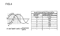
- FIG. 4 is a view showing the structure of data of the nominal position of the magnet scale and the data measured by the laser length measuring machine stored in the storage unit 70.
- the fixed laser length measuring machine 100 irradiates laser beam LB to the target 110 attached to the moving member, and using reflected light, measures the distance between the laser length measuring machine 100 and the target 110 with high accuracy.
- the positional data of the stator 20 used as a magnet scale and the highly accurate position detection data of the laser length measuring machine 100 are compared, and based thereon, the correction value corresponding to the position of the stator 20 is computed and stored in the storage unit 70.
- the data of the laser length measuring machine can be read based on the magnet scale data.
- FIG. 5 shows the configuration of a position detecting device of a linear motor using a stator 20 having the corresponding position correction data measured in advance.
- the control circuit 60 sends a command to the numerical control device 40 to move the moving member 30 to a given position.
- the distance that the moving member 30 moves is detected by the detector head 50 sensing the change of magnetic flux of the stator 20, and the detected distance is sent to the control unit 60.
- the storage unit 70 provided between the detector head 50 and the control unit 60 sends the correction value corresponding to the position data of the stator 20 constituting the magnet scale to the control unit 60, and based thereon, the control unit corrects the error caused mechanically by the stator.
- a laser length measuring machine is used as an example of the measuring device in the above description of the preferred embodiments, but a linear scale can also be adopted to carry out the present invention.
- the measurement of the position detecting data is normally carried out only once in the initial stage, but it can be carried out again if, for example, attachment error of magnets occurs by vibration or the data of the measurement device or the control unit are lost.
- the position detecting circuit, the measuring device and the control unit are provided separately from the numerical control device, but they can also be contained in the numerical control device.
Landscapes
- Engineering & Computer Science (AREA)
- Power Engineering (AREA)
- Microelectronics & Electronic Packaging (AREA)
- Physics & Mathematics (AREA)
- Chemical & Material Sciences (AREA)
- Combustion & Propulsion (AREA)
- Electromagnetism (AREA)
- Control Of Linear Motors (AREA)
- Linear Motors (AREA)
- Length Measuring Devices By Optical Means (AREA)
Applications Claiming Priority (1)
| Application Number | Priority Date | Filing Date | Title |
|---|---|---|---|
| JP2004195355A JP2006020415A (ja) | 2004-07-01 | 2004-07-01 | リニアモータ用位置検出装置 |
Publications (2)
| Publication Number | Publication Date |
|---|---|
| EP1612920A2 true EP1612920A2 (de) | 2006-01-04 |
| EP1612920A3 EP1612920A3 (de) | 2008-07-16 |
Family
ID=35169831
Family Applications (1)
| Application Number | Title | Priority Date | Filing Date |
|---|---|---|---|
| EP05013618A Withdrawn EP1612920A3 (de) | 2004-07-01 | 2005-06-23 | Positionssensor für einen Linearmotor |
Country Status (4)
| Country | Link |
|---|---|
| US (1) | US7265460B2 (de) |
| EP (1) | EP1612920A3 (de) |
| JP (1) | JP2006020415A (de) |
| CN (1) | CN100346569C (de) |
Cited By (3)
| Publication number | Priority date | Publication date | Assignee | Title |
|---|---|---|---|---|
| CN103019256A (zh) * | 2012-11-28 | 2013-04-03 | 沈阳工业大学 | 基于激光测距的直线轨道车定位系统及方法 |
| CN113162488A (zh) * | 2021-05-06 | 2021-07-23 | 深圳市航顺芯片技术研发有限公司 | 电机的转子位置测量方法、控制方法、电机转子和电机 |
| DE102013001295B4 (de) | 2012-01-26 | 2022-03-17 | Okuma Corp. | Verfahren zur Steuerung eines Linearmotors |
Families Citing this family (13)
| Publication number | Priority date | Publication date | Assignee | Title |
|---|---|---|---|---|
| JP2006020415A (ja) * | 2004-07-01 | 2006-01-19 | Yamazaki Mazak Corp | リニアモータ用位置検出装置 |
| DE102006038162A1 (de) * | 2006-08-16 | 2008-02-21 | Siemens Ag | Elektromotor mit Messsystem für Position oder Bewegung |
| JP2009089545A (ja) * | 2007-10-02 | 2009-04-23 | Hiwin Mikrosystem Corp | リニアモータ用サーボ制御装置 |
| JP5093664B2 (ja) * | 2008-02-06 | 2012-12-12 | 村田機械株式会社 | 移動体システム |
| US7591041B1 (en) * | 2008-08-08 | 2009-09-22 | Hiwin Mikrosystem Corp. | Pneumatic cleaning module for magnetic ruler of position measurement system |
| US20100072937A1 (en) * | 2008-09-25 | 2010-03-25 | Teng Hong-Chun | Mobile positioning structure for an axial rod motor |
| HUE031873T2 (en) * | 2009-06-29 | 2017-08-28 | Univ Sabanci | Position detection device for moving magnetic linear motor |
| JP5912426B2 (ja) * | 2011-11-07 | 2016-04-27 | ヤマハ発動機株式会社 | リニアコンベア |
| US9093933B2 (en) * | 2013-08-27 | 2015-07-28 | GM Global Technology Operations LLC | Method and apparatus for monitoring rotational position of an electric machine |
| JP6391843B2 (ja) * | 2015-09-01 | 2018-09-19 | 三菱電機株式会社 | アクチュエータとその調整方法 |
| JP2020100214A (ja) * | 2018-12-20 | 2020-07-02 | 日立オートモティブシステムズ株式会社 | ステアリング装置 |
| CN115473472B (zh) * | 2022-09-09 | 2023-08-22 | 深圳市软赢科技有限公司 | 应用于直线电机的位置自比较输出系统 |
| CN116659422A (zh) * | 2023-06-13 | 2023-08-29 | 穆恩直驱技术(江苏)有限公司 | 一种直线电机的直线精度检测装置 |
Family Cites Families (16)
| Publication number | Priority date | Publication date | Assignee | Title |
|---|---|---|---|---|
| JPS59185151A (ja) * | 1983-03-31 | 1984-10-20 | Seiko Instr & Electronics Ltd | リニアモ−タ |
| US5130583A (en) * | 1989-11-13 | 1992-07-14 | Ricoh Company, Ltd. | Linear motor |
| JPH04236319A (ja) * | 1991-01-18 | 1992-08-25 | Sodick Co Ltd | 位置エンコーダ装置及び位置決め装置 |
| JPH06209556A (ja) * | 1992-12-30 | 1994-07-26 | Sofutoronikusu Kk | リニアエンコーダ |
| CN2192097Y (zh) * | 1994-06-17 | 1995-03-15 | 中国科学院电工研究所 | 直流无刷直线电动机 |
| JPH08331832A (ja) * | 1995-06-01 | 1996-12-13 | Fanuc Ltd | 同一軸上で推力の切換が可能なリニアモータの構造 |
| US6008552A (en) * | 1996-12-30 | 1999-12-28 | Minolta Co., Ltd. | Linear drive device |
| JP2000139069A (ja) * | 1998-10-30 | 2000-05-16 | Minolta Co Ltd | リニアモータ駆動装置 |
| DE59906848D1 (de) * | 1998-12-03 | 2003-10-09 | Schneeberger Holding Ag Roggwi | Markierungsverfahren von Messspuren |
| EP1014539B1 (de) * | 1998-12-21 | 2007-11-14 | Nti Ag | System mit einem Linearmotor und einer Elektronikeinheit |
| DE50003742D1 (de) * | 2000-10-04 | 2003-10-23 | Nti Ag Zuerich | Verfahren zur Erhöhung der Positioniergenauigkeit eines relativ zu einem Stator bewegbar angeordneten Elements |
| JP3396216B2 (ja) | 2001-03-22 | 2003-04-14 | 恒彦 山崎 | リニアモータの製造方法 |
| JP2002281783A (ja) * | 2001-03-22 | 2002-09-27 | Tsunehiko Yamazaki | リニアモータ用位置検出装置 |
| JP2003233424A (ja) * | 2002-02-12 | 2003-08-22 | Sumitomo Heavy Ind Ltd | Xyステージの位置補正方法、装置、及び、これを用いた位置決め方法、装置 |
| JP2006020415A (ja) * | 2004-07-01 | 2006-01-19 | Yamazaki Mazak Corp | リニアモータ用位置検出装置 |
| US7262575B2 (en) * | 2004-12-01 | 2007-08-28 | Bio-Rad Laboratories, Inc. | Method and apparatus for precise positioning of an object with linear stepper motors |
-
2004
- 2004-07-01 JP JP2004195355A patent/JP2006020415A/ja active Pending
-
2005
- 2005-05-30 CN CNB2005100746910A patent/CN100346569C/zh not_active Expired - Fee Related
- 2005-06-17 US US11/156,015 patent/US7265460B2/en not_active Expired - Fee Related
- 2005-06-23 EP EP05013618A patent/EP1612920A3/de not_active Withdrawn
Cited By (3)
| Publication number | Priority date | Publication date | Assignee | Title |
|---|---|---|---|---|
| DE102013001295B4 (de) | 2012-01-26 | 2022-03-17 | Okuma Corp. | Verfahren zur Steuerung eines Linearmotors |
| CN103019256A (zh) * | 2012-11-28 | 2013-04-03 | 沈阳工业大学 | 基于激光测距的直线轨道车定位系统及方法 |
| CN113162488A (zh) * | 2021-05-06 | 2021-07-23 | 深圳市航顺芯片技术研发有限公司 | 电机的转子位置测量方法、控制方法、电机转子和电机 |
Also Published As
| Publication number | Publication date |
|---|---|
| US7265460B2 (en) | 2007-09-04 |
| EP1612920A3 (de) | 2008-07-16 |
| CN100346569C (zh) | 2007-10-31 |
| CN1716755A (zh) | 2006-01-04 |
| US20060001390A1 (en) | 2006-01-05 |
| JP2006020415A (ja) | 2006-01-19 |
Similar Documents
| Publication | Publication Date | Title |
|---|---|---|
| US7265460B2 (en) | Position detecting device of linear motor | |
| CN101971470B (zh) | 使用磁场的位置测量 | |
| KR100275916B1 (ko) | 멀티트랙 테이프 드라이브에서 자기 헤드의 위치 설정을 위한 보이스 코일 구동 위치 설정기 | |
| KR100818581B1 (ko) | 스테이지 장치 | |
| US6532791B2 (en) | Method for increasing the positioning accuracy of an element which is movably arranged relative to a stator | |
| TWI593944B (zh) | 線性編碼器裝置及基準位置檢測方法 | |
| CN101971471A (zh) | 使用磁场的位置测量 | |
| US11536558B2 (en) | Linear displacement measuring apparatus for determining an absolute position, and linear guide having such a displacement measuring apparatus | |
| US6543149B1 (en) | Coordinate measuring system | |
| CN114391090B (zh) | 带有霍尔传感器和磁体的位移测量装置 | |
| US9557730B2 (en) | Driving apparatus and article processing apparatus | |
| EP1972899B1 (de) | Positionsdetektor mit Neigungssensor | |
| CN216696162U (zh) | 一种钢丝帘布检测校准装置 | |
| KR101854177B1 (ko) | 부품에 대한 가공 기구 위치 정렬 장치 및 방법 | |
| JP5073603B2 (ja) | アブソリュート型リニアエンコーダ、及び、その位置調整方法 | |
| CN114166930A (zh) | 一种钢丝帘布检测校准装置及检测校准方法 | |
| JP2007114121A (ja) | 位置検出装置、交換レンズおよびカメラ | |
| JP2012016769A (ja) | 視覚センサのマウント装置と方法 | |
| JP2003254703A (ja) | 移動体システムおよび移動体の位置検出方法 | |
| KR102748439B1 (ko) | 스케일리스 리니어 모터 시스템 및 그 제어 방법 | |
| JP2003222512A (ja) | 位置検出機構を備えた移動装置 | |
| JP2003057072A (ja) | リニアエンコーダ | |
| KR100547226B1 (ko) | 위치 보정이 가능한 변위측정 센서 | |
| KR20230050554A (ko) | 리니어 모터용 엔코더 | |
| JPH0662304U (ja) | 磁気リニアスケール |
Legal Events
| Date | Code | Title | Description |
|---|---|---|---|
| PUAI | Public reference made under article 153(3) epc to a published international application that has entered the european phase |
Free format text: ORIGINAL CODE: 0009012 |
|
| AK | Designated contracting states |
Kind code of ref document: A2 Designated state(s): AT BE BG CH CY CZ DE DK EE ES FI FR GB GR HU IE IS IT LI LT LU MC NL PL PT RO SE SI SK TR |
|
| AX | Request for extension of the european patent |
Extension state: AL BA HR LV MK YU |
|
| RIN1 | Information on inventor provided before grant (corrected) |
Inventor name: MIYAKAWA, NAOOMI Inventor name: YAMAZAKI, TSUNEHIKO |
|
| PUAL | Search report despatched |
Free format text: ORIGINAL CODE: 0009013 |
|
| AK | Designated contracting states |
Kind code of ref document: A3 Designated state(s): AT BE BG CH CY CZ DE DK EE ES FI FR GB GR HU IE IS IT LI LT LU MC NL PL PT RO SE SI SK TR |
|
| AX | Request for extension of the european patent |
Extension state: AL BA HR LV MK YU |
|
| RAP1 | Party data changed (applicant data changed or rights of an application transferred) |
Owner name: YAMAZAKI MAZAK CORPORATION |
|
| RIN1 | Information on inventor provided before grant (corrected) |
Inventor name: YAMAZAKI MAZAK CORPORATION |
|
| 17P | Request for examination filed |
Effective date: 20080909 |
|
| AKX | Designation fees paid |
Designated state(s): DE FR GB IT |
|
| 17Q | First examination report despatched |
Effective date: 20090626 |
|
| STAA | Information on the status of an ep patent application or granted ep patent |
Free format text: STATUS: THE APPLICATION IS DEEMED TO BE WITHDRAWN |
|
| 18D | Application deemed to be withdrawn |
Effective date: 20091107 |