EP1610351A2 - Transformateur et source d'alimentation utilisant transformateur - Google Patents
Transformateur et source d'alimentation utilisant transformateur Download PDFInfo
- Publication number
- EP1610351A2 EP1610351A2 EP05253851A EP05253851A EP1610351A2 EP 1610351 A2 EP1610351 A2 EP 1610351A2 EP 05253851 A EP05253851 A EP 05253851A EP 05253851 A EP05253851 A EP 05253851A EP 1610351 A2 EP1610351 A2 EP 1610351A2
- Authority
- EP
- European Patent Office
- Prior art keywords
- terminals
- terminal
- bobbins
- windings
- wound
- Prior art date
- Legal status (The legal status is an assumption and is not a legal conclusion. Google has not performed a legal analysis and makes no representation as to the accuracy of the status listed.)
- Withdrawn
Links
Images


Classifications
-
- H—ELECTRICITY
- H01—ELECTRIC ELEMENTS
- H01F—MAGNETS; INDUCTANCES; TRANSFORMERS; SELECTION OF MATERIALS FOR THEIR MAGNETIC PROPERTIES
- H01F38/00—Adaptations of transformers or inductances for specific applications or functions
- H01F38/08—High-leakage transformers or inductances
- H01F38/10—Ballasts, e.g. for discharge lamps
-
- H—ELECTRICITY
- H01—ELECTRIC ELEMENTS
- H01F—MAGNETS; INDUCTANCES; TRANSFORMERS; SELECTION OF MATERIALS FOR THEIR MAGNETIC PROPERTIES
- H01F27/00—Details of transformers or inductances, in general
- H01F27/28—Coils; Windings; Conductive connections
- H01F27/29—Terminals; Tapping arrangements for signal inductances
-
- H—ELECTRICITY
- H01—ELECTRIC ELEMENTS
- H01F—MAGNETS; INDUCTANCES; TRANSFORMERS; SELECTION OF MATERIALS FOR THEIR MAGNETIC PROPERTIES
- H01F27/00—Details of transformers or inductances, in general
- H01F27/28—Coils; Windings; Conductive connections
- H01F27/32—Insulating of coils, windings, or parts thereof
- H01F27/324—Insulation between coil and core, between different winding sections, around the coil; Other insulation structures
- H01F27/326—Insulation between coil and core, between different winding sections, around the coil; Other insulation structures specifically adapted for discharge lamp ballasts
-
- H—ELECTRICITY
- H01—ELECTRIC ELEMENTS
- H01F—MAGNETS; INDUCTANCES; TRANSFORMERS; SELECTION OF MATERIALS FOR THEIR MAGNETIC PROPERTIES
- H01F27/00—Details of transformers or inductances, in general
- H01F27/28—Coils; Windings; Conductive connections
- H01F27/2823—Wires
- H01F27/2828—Construction of conductive connections, of leads
-
- H—ELECTRICITY
- H01—ELECTRIC ELEMENTS
- H01F—MAGNETS; INDUCTANCES; TRANSFORMERS; SELECTION OF MATERIALS FOR THEIR MAGNETIC PROPERTIES
- H01F38/00—Adaptations of transformers or inductances for specific applications or functions
- H01F38/42—Flyback transformers
Definitions
- This invention relates generally to wound-rotor type transformers for use in inverters such as driving cold cathode type fluorescent lamps and power source devices utilizing the wound-rotor type transformers.
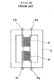
- the wound-rotor type transformers generally are such as shown in FIG 18 that a primary winding P and secondary winding S are wound on a core by means of a bobbin (drawing is omitted), and secondary output terminals T3 and T4 connected to both terminals of the secondary winding S are provided on a terminal base of output sides of primary input terminals T1 and T2 connected to the primary winding P are provided on a terminal base of input side of the transformer, and secondary output terminals T3 and T4 connected to both terminals of the secondary winding S are provided on the terminal base of output sides.
- the wound-rotor type transformer is provided on a printed circuit board (PCB), and a discharge type lamp such as cold cathode fluorescent lamp
- the wound-rotor type transformer is mounted on the printed circuit board so that its secondary output terminal is opposed to the connector installed on the printed circuit with a shortest distance, and the secondary output side is connected to the lamp through the connector.
- the output side of the wound-rotor transformer is disposed in opposition to the connector, sufficient insulation becomes required due to a large potential difference between the secondary output terminals connected to both terminals of the secondary winding.
- grooves for insulation are provided on the printed circuit board in order to enlarge the insulation distance between a secondary output terminal at high tension side connected to one end of the secondary winding and a lead wire connected to the secondary output terminal, and between a secondary output terminal connected to the other terminal of the secondary winding and a lead wire connected to the secondary output terminal, whereby an air gap is formed between the secondary output terminals but there are problems such as occurrence of discharge between the secondary output terminals or generation of lead current between both the output terminals that allows the flowing of electric current of high tension over the printed circuit board, and therefore, such arrangements are not necessarily safe measures.
- Objects of the present invention are to solve the foregoing problems.
- the wound-rotor type transformers according to the present invention has a construction that a primary winding and a secondary winding are mounted on the bobbin into which the core is inserted.
- the terminal base is provided at the side where a high tension terminal of the bobbin is disposed, and the first terminal connected to one terminal of the secondary winding is mounted on the terminal base at the side where the high tension terminal is disposed.
- the second terminal connected to the other terminal of the secondary winding mounted on the bobbin is provided at the side where the rearward low tension terminal is disposed which has a predetermined distance from the side where the high tension terminal of the bobbin is disposed.
- the second terminal is used as a ground terminal.
- the wound-rotor type transformer according to the present invention can be divided to the side where the high tension terminal is disposed and the side where the low tension terminal is disposed so that it elevates insulation characteristics between both the termials of the secondary winding of the wound-rotor type transformer thereby driving the wound-rotor type transformer safely.
- the present invention provides a power source device that drives lamps such as the cold cathode type fluorescent lamp with the high tension output at the secondary side of the wound-rotor type transformer, wherein the primary winding is connected to an AC output circuit, and the second terminal is grounded, and the first terminal is connected to the lamp.
- lamps such as the cold cathode type fluorescent lamp with the high tension output at the secondary side of the wound-rotor type transformer, wherein the primary winding is connected to an AC output circuit, and the second terminal is grounded, and the first terminal is connected to the lamp.
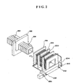
- numeral 182 denotes a core constituting a square type frame core formed by joining two pieces of [ shape and ] shape.
- a primary bobbin 184 is inserted into the part of the parallel portion of the core 182.
- a terminal base 186 is fixed to the center of the primary bobbin 184, and primary terminals 188, 189 are provided on the terminal base 186.
- a primary winding 192 is mounted on the bobbin 184, and the primary input terminals 188, 190 are connected to both terminals of the primary winding 192 by means of the lead wire.
- a pair of the secondary bobbins 191, 194 are inserted into the outside of the primary bobbin 184 which are positioned at both sides of the terminal base 186.
- a partition 196 of each end of the pair of the secondary bobbins 191, 194 contacts each face of both sides of the terminal base 186.
- the partition 196 of the secondary bobbins 191, 194 is omitted from the drawing to avoid complication of illustration.
- secondary windings 198, 200 are wound by two pieces of twofold wires a, b.
- Start winding terminals of the secondary windings 198, 200 consisting of twofold wires are connected to secondary high tension terminals 206, 208, 210, 212 provided on each terminal base 202, 204 of the respective terminal bases 202, 204 of the secondary bobbins 191, 194 by means of the lead wire, and the finish winding terminals are connected to the ground terminals 214, 216, 218, 220 by means of the lead wire.
- the secondary windings 198 and 200 are wound mutually in counter direction as shown in FIG 1, and the number of windings are mutually identical.
- the terminals 206, 208, 210 and 212 are disposed at the side (the side where the high tension terminal is disposed) facing the connector 128 connected to the lamp such as the cold cathode type fluorescent lamp that is disposed on the printed circuit board at the shortest distance.
- the secondary windings 214, 216, 218, 220 are disposed at the side where the low tension terminal of the rearward at a predetermined distance relative to the side where the high tension terminal is disposed.
- the wound-rotor type transformer is divided into the high tension region E in the upper side in FIG 1 on the basis of the line G, and into the low tension region F in the lower side.
- the secondary terminals 206, 208 and the secondary terminals 210, 212 are mutually in counter phase, and the terminals are in such a relationship that when the one part is the plus, the another part is the minus.
- the secondary terminals 206, 208 and the secondary terminals 210, 212 may be mutually in identical phase.
- the relationship between the primary winding 192 and the secondary windings 198, 200 is such that in the double layer structure of the bobbins, the secondary windings 198, 200 are disposed at both sides of the primary winding that enables to form the multiple output by such a simple structure.
- the high tension may be applied to the twofold parallel windings constituting the secondary windings but since this high tension is mutually at the identical potential, there is no chance of short circuiting between the parallel secondary windings or the leakage of electric current.
- the other parallel portion 182a of the core 182 can be formed in similar form, and in case where the core 182 is made of the structure of the bivertical symmetry in FIG 1, the primary sides are connected serially or in parallel to form one input, and 8 outputs can be materialized.
- the number of windings of the secondary windings is set to be 3 pieces or 4 pieces whereby further multiple outputs can be materialized.
- the multiple output type winding transformer 4 of the foregoing embodiment as shown in FIG 1 is operated by a self-excited oscillation circuit as shown in FIG 3.
- a self-excited oscillation circuit as shown in FIG 3.
- the winding transformer of the multiple output structure there is no particular limit to the double layer structure of the bobbins, and the parallel winding of the secondary windings on the bobbin of the conventional structure to constitute the multiple output type wound-rotor type transformer.
- numeral 52, 54, 56, 58 denote switching elements consisting of EFT, and commutation diodes 60, 62, 64, 66 are connected between the source and drain of each switching element.
- Gate control circuits 68, 70, 72, 74 are connected to each gate of the switching elements 52, 54, 56, 58 and among them, a PWM control circuit 76 is connected to the gate control circuits 68, 72, and the gate control circuits 70, 74 are connected to a logic circuit 78.
- the PWM control circuit 76 controls a conductance angle of the switching elements 52, 56 so that it receives signals from a lamp current detecting circuit 80 that detects electric current flowing in the lamp 46 and a level of this signal becomes a set value given by the line 82.
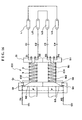
- Numeral 44 denotes a wound-rotor type transformer of 1 input 8 output type fixed to the circuit-board (drawing is omitted), and 4 pairs of pair lamps L1, L2, L3, L4 to which 2 pieces of cold cathode type fluorescent lamps 46 are connected in series are disposed at the output side of the transformer.
- Each terminal of the lamp pairs L1, L2, L3, L4 is respectively connected to high tension terminal side of a pair of the secondary side windings corresponding to the winding type transformer 44.
- Each terminal of the secondary side windings S1, S3, S5, S7 is earthed by means of respective current detecting resistors RS, and the secondary side windings S2, S4, S6, S8 are earthed by means of the lead wires.
- Each terminal of each resistor RS is connected to a lamp current detecting circuit by means of a capacitor C and a diode D1 for rectification.
- a phase detecting circuit 51 is connected to a middle point P of an LC series resonance circuit by means of the lead wire 27.
- a logic circuit 78 is constructed to create signals for turning the switching element ON and OFF on the basis of resonance phase signals at primary side from the phase detecting circuit 51 connected to the lead wire 27 and transmits on-off control signals to the gate control circuits 68, 72 by means of the PWM control circuit 76 and transmits the on-off control signals to the gate control circuit 70, 74.
- the phase detecting circuit 51 transmits corrected phase signals delayed by 90 degrees from the phase voltage signals of the middle point P of the LC series resonance circuit to the logic circuit 78. The signals become an identical phase with the electric current flowing in the LC series resonance circuit at primary side.
- the voltage of the terminal at the primary side of the transformer 44 further lowers after exceeding the OV upon the passing of the phase time of 90 degrees electrically even if the charge voltage of the capacitor CT reaches the DC power source voltage, and moreover, it becomes a maximum value of the minus upon passage of the phase time of 90 degrees
- the logic circuit 78 outputs the switching control signals alterately as described hereinabove.
- the logic circuit 78 creates photo-adjusting control signals on the basis of output signals of a photo-adjusting control circuit 84 to which the photo-adjusting control signals are inputted, and the burst control of the ON-OFF of the switching element and the control of the switch-on-pulse width of the PWM control circuit 76 are carried out by the photo-adjusting control signals whereby the brightness of the lamps 46, 46 is contstantly maintained, and the brightness is to be optionally set from the brightness zero to 100% according to the photo-adjusting signals.
- an overcurrent detecting circuit 88 is connected to the logic circuit, and when the overcurrent flows in the lamp 20, the logic circuit 78 detects it, and prevents the flow of the overcurrent by feeding the signals preventing the overcurrent to the PWM control circuit 76.
- a starting compensation circuit 88 are connected to shunt resistors RS of an energizing circuit of the lamp 46, thereby the current signals of each pair of the lamps are inputted to the circuit 88.
- the starting compensation circuit 88 inputs the starting compensation signals to the phase detecting circuit 51 to positively start the self-excited oscillation circuit when the power source is ON, off.
- the phase detecting circuit 51 outputs starting signals for self-excited oscillation to the logic circuit 78 upon receiving the starting compensation signals.
- the starting compensation circuit 88 is so set that the lamp does not start the discharge even if the electric current flows in the predetermined direction determined by the logic to the primary side of the transformer after the signals whose phase is corrected enters into the logic circuit 78 from the phase detecting circuit 51.
- the starting compensation circuit 88 is provided for the starting compensation of such a case.
- the starting compensation circuit 88 judges if the lamp 46 is lighted ON or not by detecting the electric current flowing in the lamp 46, and in case, the lamp is not lighted ON, transmits the starting compensation signals to the phase detecting circuit 51 until the lamp is lighted ON.
- the phase detecting circuit 51 receives the starting compensation signals and outputs the starting signals to the logic circuit 78 until the lamp 46 is lighted ON.
- the voltage of the photo-adjusting signals is compared with the output voltage of a triangular wave oscillation circuit built in the control circuit 84 and generates burst photo-adjusting signals of a predetermined period.
- the circuit 84 turns ON and OFF the entire logic signals and as a result, controls the brightness. This method makes the adjustment freely from the light-OFF to the total light-ON, but since the lamp 46 is turned ON and OFF with a period of the photo-adjusting signals, it becomes necessary to make a confirmation of starting and positive starting for each period.
- the starting compensation circuit 88 in order to materialize the positive light-on, transmits the starting compensation signals to the phase detecting circuit 51 in the beginning.
- the switching elements 52, 58 are turned ON with a predetermined pulse width so that the electric current flows in the direction 11.
- the electric current flows to the primary windings of the capacitor CT and the transformer 44, and the signals are transmitted to the phase detecting circuit 51 through the lead wire 27, and the electric current flows mutually to I2, I1, I2, I1, and the self-excited oscillation circuit starts the oscillation with the detected resonance frequency.
- the starting compensation circuit 88 forms an initial period reset. If the lamp is lighted on, it performs the resetting again, and transmits the initial starting signals to the logic circuit 78 through the phase detecting circuit 51.
- a lamp open circuit 90 is constructed in such a way that it is connected to each shunt resistor RS at the secondary side of the wound-rotor type transformer 44, and detects the electric current of the lamp at the secondary side.
- the lamp 46 When the lamp 46 is out of order and the lamp current does not flow, namely, the state of the lamp open, transmits the signals to the logic circuit 78, and shuts out the control circuit consisting of the logic circuit 78, PWM control circuit 76 and gate control circuits 68, 70, 72, 74.
- the overcurrent detecting circuit 86 transmits the signals to the logic circuit 78 when the PWM control circuit is in trouble or the wiring of the lamp 46 is shortcircuited to shuts out the control circuit.
- the electric current of the DC power source flows to the primary side winding of the wound-rotor type transformer 10 through the switching elements 52, 58 in the direction of I1 or through the switching elements 56, 54 in the direction of I2.
- the wound-rotor type transformer 44 With the energization of the primary winding, it starts the self-excited oscillastion circuit and the wound-rotor type transformer 44 ganerates the resonance voltage.
- the frequency of the resonance voltage at the primary side of the wound-rotor type transformer 44 is supplied to the phase detecting circuit 51 by the lead wire 27.
- the logic circuit 78 and the PWM control circuit 76 drive the gate control circuits 68, 70, 72, 74 on the basis of the phase signals from the phase detecting circuit 51, and performs the ON and OFF control of the switching elements 52, 54, 56, 58.
- the electric current flows alternately in the directions of I1 and I2 by the ON and OFF of the switching elements 52, 54, 56, 58, and the self-excited oscillation circuit performs the self-excited oscillation with the resonance frequency at the primary side of the wound-rotor type transformer 10.
- the self-excited oscillation circuit performs the self-excited oscillation with the resonance frequency at the primary side of the wound-rotor type transformer 10.
- the embodiment of this invention provides the resonance voltage higher than the input power source voltage at the primary side of the wound-rotor type transformer whereby it allows the saving of number of windings at the secondary side of the wound-rotor type transformer and provides a margin of the spaces for the windings at the secondary side.
- the wound-rotor type transformer to be used in this invention can be transformed into the wound-rotor type transformer of 1 input multiple output type with the size almost same with the regular 1 input 1 output type wound-rotor type transformer.
- a transformer 100 is provided with a pair of bobbins 102, 104 formed by joining mutually in parallel, and secondary windings M1, M2 are mutually wound in mutually counter directions with mutually the same number of windings by means of two pieces of twofold wires a, b between terminal bases B1, B2 of the bobbins 102, 104 respectively.
- a common core 108 is inserted and disposed in a hole 106 of said pair of the bobbins 102, 104.
- the core 108 as shown in FIG 6, consists of I type core 108b and 108c, and a coupled core 108a connected to the cores and forming a closed magnetic path.
- An end of winding start side (high tension side) of the secondary windings M1, M2 are connected to the terminals S1, S2, S3, S4 of the terminal base B1, and an end of winding finish side (low tension side) of the respective secondary windings M1, M2 are connected to the terminal A of the terminal base B2 of the bobbin 102 and the terminal B of the terminal base B2 of the bobbin 104.
- the primary winding 110 is wound.
- any optional constructions such as a construction wherein the primary winding 110 is wound between the terminal bases B2, B3 of the bobbins 102, 103, and they are connected in series or parallel, or a singular construction wherein windings are applied over across the bobbins 102, 104 can be employed.
- the primary winding 110 is connected to the output side of the inverter circuit such as fullbridge type self-excited oscillation circuit as shown in FIG 3 or the like.
- FIG. 7 illustrates the easy understanding of the circuit of FIG 4.
- the high tension+HV of the terminals S1, S2 ad the high tension-HV of the terminals S3, S4 are in mutually counter phase relationship, and the high tension is applied to the lamps L1, L4 and the L2, L3 by the secondary side of the transformer.
- the connecting point 01 of the lamps L1, L4 and the connecting point 02 of the lamps L2, L3 become the zero point from the dummy point of view.
- the electric current flows in a circle from the terminal A of the one bobbin 102, passing through the secondary winding M1 of the one bobbin 102, and passing through the terminal S1, the ballast capacitor C1, the lamp L1, the lamp L4, the capacitor C4, the terminal S4, the secondary winding M1 of the other bobbin 104, the terminal B, and passing through the ground and reaching the terminal A.
- the electric current flows in a circle from the terminal A of the one bobbin 102, passing through the secondary winding M2 of the one bobbin 102, the terminal S2, the ballast capacitor C2, the lamp L2, the lamp L3, the capacitor C3, the terminal S3, the secondary winding M2 of the other bobbin 104, and the terminal B and passing through the ground and reaching the terminal A.
- the magnitude of the lamp current of the lamps L1, L2, L3, L4 becomes a uniform by the electric current flowing in the loop.
- the electric current flowing in the secondary windings M1, M2 of the bobbin 102 and the secondary windings M1, M2 of the bobbin 104 are on the identical core so that the electric current flowing in the secondary windings M1, M2 of the bobbin 102 performs the diverting action, namely, the electric current balancing action.
- the similar diverting action (electric current balancing action) is automatically made, and finally, each electric current flowing through 4 pieces of the lamps L1-L4 become the same.
- the transformer 100 denoted in FIG 4 is provided on the printed circuit board and the terminal base B1 at the side facing connector (drawing is omitted) connected to the lamps L1-L4 is disposed at the side where the high tension terminal is installed, and the terminal base B2 is disposed rearward at a predetermined distance against the side where the high tension terminal is disposed, and the right side is divided to the high tension region E and the left side is divided to the low tension region F on the basis of the line G.
- a pair of the cold cathode type fluorescent lamps that are serially connected may be formed in a piece of long cold cathode type fluorescent lamp of curved U-form, for example, like lamps L1, L4, L2, L3 in FIG 4 which are displayed in the foregoing embodiment and embodiments to be described hereinafter.
- this invention is not particularly limited to the embodiment of counter phase of the terminals S3, S4 against the terminals S1, S2, and it may be the identical phase.
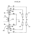
- FIG 9 illustrates that a shunt transformer (electric current balancer) 112 is disposed between the terminals A and B, and the terminal A is connected to one terminal of the winding 114 of one part of the shunt transformer 112, and the other terminal of the winding 114 is earthed, and the terminal B is connected to the other terminal of the winding 116 of the other part of the shunt transformer 112, and the one terminal of the winding 116 is earthed.
- Other constructions of FIG 9 are identical with the circuit illustrated in FIG 8. With this construction, the lamp electric current of the lamps L1, L2, L3, L4 are arranged to be made more uniform.
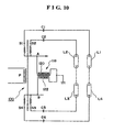
- FIG 10 illustrates that the terminals A, B are connected to one terminal of each winding 120, 122 of the shunt transformer 118, and the other terminals of each winding 120, 122 of the shunt transformer 118 are made to be a uniform terminal that is connected to the ground.
- the number of the line (wire) of the parallel winding of the secondary windings is not limited to 2 pieces, and it is possible to make the wire to be multiple pieces, and to be the parallel winding, and also, the series connection of the lamps is not limited to 2 pieces, and more than 3 pieces may be connected in series.
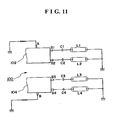
- the construction is illustrated wherein 2 pieces of the bobbins are used, and as shown in FIG 4, 4 pieces of the secondary windings M1, M2 are provided, and 2 pieces of the primary windings and 4 pieces of the lamps are provided, but as shown in FIG 11, it is feasible to form the construction wherein 2 pieces of the secondary windings ad one piece of the primary winding and 2 pieces of the lamps are provided.
- the construction of the transformer 100 is identical with the construction of the transformer 100 illustrated in FIG 4. By the way, it is feasible to form the construction of the transformer 100 consisting of 2 pieces of the transformers independent for each of the bobbins 102, 104.
- Each transformer is formed wherein the primary winding 100 is provided for each of bobbins 102, 104, and each primary winding 110 is connected in series or in parallel.
- Two pieces of the lamps L1, L2 are mutually and serially connected, and the one electrode of the one lamp is connected to the terminal S1 by means of the ballast capacitor C1, and the other electrode of the other lamp L2 is connected to the terminal S2 by means of the ballast capacitor C2.
- the other electrodes of 2 pieces of the lamps L1, L2 are connected to the ground.
- the connection of the lamps L3, L4 is identical with the foregoing construction.
- Each terminal of the windings 122, 124 of the shunt transformer 120 is connected to a common connecting point 126 of the lamps L1, L2 and a common connecting point 128 of the lamps L3, L4, and each other terminal of the windings 122, 124 is connected to the ground.
- the electrodes of the lamps L1, L2 are connected to the terminals S1, S2 of the transformer 100 by means of the ballast capacitors C1, C2, and the electrodes of the lamps L3, L4 are connected to the terminals S3, S4 of the transformer 100 by means of the respective ballast capacitors C3, C4.
- the other construction is identical with the construction illustrated in FIG 4.
- the windings 122, 124 of the shunt transformer (electric current balancer) 120 are wound mutually in counter phase, and the the operation is carried out so that magnitude of the electric current flowing in the windings 122, 124 becomes identical, and the lamp electric current flowing in the lamps L1, L2, L3, L4 become uniform by the shunt operation (electric current balancing operation) of this transformer.
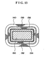
- FIG 13 illustrates the another embodiment of the parallel winding of the wires in the transformer.
- the first secondary winding 136 is laminated and is wound on the bobbin 132 with built-in core 130 by means of an insulator member 134
- the second secondary winding 140 is laminated and is wound with the same number of windings with the first secondary winding 136 by means of the insulator material over the first secondary winding 136, and the first and the second secondary windings 136, 140 corresponding to the 2 pieces of the windings a, b shown in FIG 4 may be formed in a lamination structure.
- the foregoing secondary windings 136 may be formed in bifilar winding consisting of more than 2 pieces of the windings, and similarly, the second secondary windings 140 may be formed in bifilar winding consisting of more than 2 pieces of the windings.
- 1 input 4 output winding type transformer can be constructed.
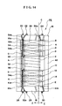
- numeral 2 is a bobbin (insulator member) of a wound-rotor type transformer, and a plurality of plate type partitions 4, 6, 8, 10, 12, 14 of square shape with insulative pressure resistance are fixed to its angular cylindrical portion at a predetermined interval, and a concave portion for winding is formed on the bobbin (insulator member).
- Terminal bases 16, 18 extending in right angular direction relative to axial direction of the bobbin (insulator member) are fixed to both ends of the bobbin (insulator member) 2 in its axial direction, and the terminals 20, 22, 24, 26, 28, 30 are fixed to the terminal bases.
- the terminals 24, 30 are disposed at high tension side of the transformer at the right side of the line G
- the terminals 20, 22, 26, 28 are disposed at low tension side at the left side of the line G.
- the secondary high tension terminal 24 is disposed at one side of the terminal base 16 at one end side of the bobbin (insulator member) 2, and the primary input terminal 22 and the secondary ground terminal 20 are disposed at the other side.
- the primary input terminal 22 and the ground terminal 20 are disposed at the other side of the terminal base 16 which is separate as much as possible in order not to be influenced with the high tension of the secondary high tension terminal 24.
- the secondary high tension terminal 30 is disposed at one side of the terminal base 18 at the other end side of the bobbin (insulator member) 2, and the primary input terminal 28 and the secondary ground terminal 26 are disposed at the other side which is far separated as much as possible therefrom.
- An insulator member of elongate type insulation material is mounted between guide mounting grooves 16a, 18a formed at the fitting sides of the terminals 20, 22 and 26, 28 of the terminal bases 16, 18, and the concave portion 34b of the insulator member 34 is fitted into the outer edges of the corresponding partitions 4, 6, 8, 10, 12, 14.
- the insulator member 34 is provided with a lead wire guide portion 34a formed with an open groove at the side opposite to the side facing the bobbin (insulator member) 2 along its longitudinal direction.
- the primary winding 32 is wound, for example, in clockwise direction with its one end side as the start winding in the concave portion surrounded by the partitions 8, 10 in the center of the bobbin (insulator member) 2.
- a lead wire 32a at the start winding side A of the primary winding 32 is disposed in the guide portion 34a of the lead wire of the insulator member 34 through a hole 36 formed on the insulator member 34, and is led to one end side of the bobbin (insulator member 1) 2 passing through the lead wire guide portion 34a and is connected to the primary side input terminal 22 by means of the guide groove formed on the terminal base 16.
- the lead wire 32a of the finish end side of the primary winding 32 is disposed in the lead wire guide portion 34a of the insulator member 34 through a hole 38 formed on the insulator member 34, and is led to the other end side of the bobbin (insulator member) 2 through the lead wire guide portion 34a, and is connected to the input side input terminal 28 by means of the guide groove formed on the terminal base 18.
- the first primary winding 39 is sequentially wound with clockwise winding in each concave portion between the terminal base 16 and the partition 4, and between the partitions 4, 6 and between the partitions 6, 8 at one side of the primary winding 32 on the bobbin (insulator member) 2 with the one end side B of the bobbin (insulator member) 2 as the winding start.
- a lead wire 39a at the winding start of the first secondary winding 39 is led to the secondary high tension terminal 24 through a groove formed on the terminal base 16, and is connected to the terminal.
- a lead wire 39b at the finish end side C of the first secondary winding 39 is disposed inside of the lead wire guide portion 34a of the insulator member 34 by means of a hole 36, and passing through the lead wire guide portion 34a along with the lead wire 32a, and is led to one end side of the bobbin (insulator member) 2, and is connected to the ground terminal 20 at the secondary side by means of the guide groove formed on the terminal base 16.
- the second secondary winding 41 is sequentially wound with clockwise winding in each concave portion between the partitions 10, 12 and between the partitions 12, 14 and between the partitions 14, terminal base 18 with the side D in contact with the partition 10 as the winding start at the other side of the primary winding 32 in the center of the bobbin (insulator member) 2.
- the first and second secondary windings 39, 41 disposed in symmetry at the right and left of the primary winding 32 are of identical construction.
- the lead wire 41b of the finish end side E of the second secondary winding 41 is led to the secondary high tension terminal 30 passing through the groove formed on the terminal base 18 and is connected to the terminal.
- the lead wire 41a at the winding start end side D of the second secondary winding 41 is disposed in the lead wire guide portion 34a of the insulator member 34 by means of the hole 38, and passing through the lead wire guide portion 34a along with the lead wire 32a of the primary winding 32 and is led to the other end side of the bobbin (insulator member) 2 and is connected to the secondary side ground terminal 26 by means of the guide groove formed on the terminal base 18.
- both terminals of the primary winding 32 between the partitions 8, 10 come to contact with the low voltage ground side of the secondary windings 39, 41 whereby the difference between the voltage of the primary winding 35 and the voltage of the secondary windings 39, 41 which are adjacent windings becomes smaller.
- a simple structure can be formed with respect to the insulation pressure resistance structure between the primary winding 32 and the secondary windings 39, 41. Even if, namely, the primary winding and the lead wire at the secondary ground side are disposed in parallel in the common lead wire guide portion 34a as there is small potential difference between the primary winding 32 and the ground side of the secondary windings 39, 41, no problem arises with respect to the insulation pressure resistance.
- a plurality of lead wire guide portions are provided on the insulator member 34, and each piece of the lead wire may be disposed on the lead wire guide portion.
- Numeral 42 is a core, and 2 pieces of E-shaped cores are joined, and an external edge portion is disposed at the outside of the bobbin (insulator member) 2, and an inside portion 42a of the core 42 is disposed in the cylindrical portion of the bobbin (insulator member) 2.
- the foregoing wound-rotor type fluorescent lamps 46, 46 of 1 input 2 output construction are driven in a condition which are free of unevenness in brightness by using this transformer.
- two pieces of lamps 46, 46 whose both terminals are connected to the high tension side of the secondary windings 39, 41 provide no difference in the brightness at both terminals of the lamps.
- a series or parallel resonance circuit is provided at the primary side of the transformer.
- the 1 input 2 output wound-rotor type transformer has a tendency of concentrating the heat generation by the primary coil and the core in the central portion of the transformer but this heat generation is caused in the central portion of the transformer so that the balance of the coupling with the secondary windings is maintained in a preferable condition, and the transformer operates efficiently.
- the heat generation concentrates at the one side of the transformer, the imbalance occurs in the coupling of the primary winding and the secondary windings that obstructs the better efficiency of its operation.
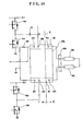
- FIG 15 An embodiment shown in FIG 15 as reference is described in the following wherein the wound-rotor type transformer 44 is operated by a self-excited oscillation circuit that generates the resonance voltage at the primary side of the wound-rotor type transformer.
- the self-excited oscillation circuit is identical with the circuit shown in FIG 3, and the self-excited oscillation circuit will be described by referring to a circuit shown in FIG 3.
- numerals 52, 54, 56, 58 are switching elements consisting of FET, and commutation diodes 60, 62, 64, 66 are connected between the source and drain of each switching elements.
- Gate control circuits 68, 70, 72, 74 are connected to each gate of the switching elements 52, 54, 56, 58, and among the gate control circuits, the gate control circuits 68, 72 are connected to a PWM control circuit 76, and the gate control circuits 70, 74 are connected to a logic circuit 78.
- the PWM control circuit receives signals from a lamp electric current detecting circuit 80 that detects the electric current flowing in the lamps, and controls the continuity angle of the switching elements 52, 56 so that the level of the signals become a set value.
- the transformer 44 is fixed to the print substrate (drawing is omitted), and two pieces of the cold cathode type fluorescent lamps 46, 46 are connected in series, and each terminal of the fluorescent lamps 46, 46 is respectively connected to the sides of the high tension terminals side of the secondary coils 39, 41 of the wound-rotor type transformer 44.
- Each terminal of the secondary side windings 39, 41 is earthed by means of the respective resistors.
- One resistor 48 constitutes an electric current detecting circuit, and is connected to a lamp open. lamp short detecting circuit 90 and a starting compensation circuit 88 by means of the lead wires.
- the phase detecting circuit 51 is connected to a middle point of a LC series resonance circuit.
- the logic circuit 78 is constructed so that it creates signals for turning the switching elements ON and OFF on the basis of primary side resonance phase signals from the phase detecting circuit 51 connected to the lead wires 27, and transmits the ON and OFF signals to the gate control circuits 68, 72 by means of the PWM control circuit 76, and transmits the ON, OFF control signals to the gate control circuits 70, 74.
- the phase detecting circuit 51 transmits the corrected phase signals delayed by 90 degrees from the phase voltage signals of the middle point of the LC series resonance circuit to the logic circuit 78.
- the signals become the same phase with the electric current flowing in the primary side LC series resonance circuit.
- the electric current flowing in the primary side series resonance circuit is such that even if the charge voltage of the capacitor C1 reaches the DC power source voltage, the voltage at the primary side terminal of the transformer 44 further lowers beyond OV after passing the phase time of 90 degrees electrically, and becomes a maximum value of the minus after passing the phase time of 90 degrees.
- the logic circuit 78 outputs alternately the switching control signals.
- the self-excited oscillation circuit oscillates in self-excitation manner with the primary side resonance frequency of the wound-rotor type transformer 100. There occurs no unevenness in brightness since the high tension of the secondary side winding of the transformer is applied to the electrodes of each terminal of two pieces of the fluorescent lamps 46, 46.
- the secondary high tension terminals 24, 30 are disposed in parallel by sandwiching the bobbin (insulator member) 2 at right side of the terminal bases 16, 18 extending in right angle direction relative to the axial direction of the bobbin (insulator member) 2 and the primary input terminals 22, 28 are disposed in parallel by sandwitching the bobbin (insulator member) 2 with the ground terminals 20, 26 at the left side.
- the lamps 46, 46 can be connected to the wound-rotor type transformer 44 by means of the connector 128 at the shortest distance in simple manner, and the connecting wiring between the transformer 44 and the lamps 46, 46 and connecting wiring with the self-excited oscillation circuit can be made extremely in simple structure.
- the high tension terminals are disposed at the right side of the wound-rotor type transformer, and the low tension terminals are disposed at the left side so that an edge surface distance between the high tension side E and the low tension side F of the transformer can be reserved in wide range, and a stable operation of the transformer and a smaller size unit can be materialized.
- the wound-rotor type transformer 100 shown in FIG 16 is almost identical with the transformer 100 shown in FIG 4, two pieces of terminals Q1, Q2 ad Q3, Q4 are provided for each bobbin 102, 104 on the terminal board B2 as illustrated in FIG 16.
- terminals of the secondary winding M1 at the bobbins 102, 104 sides are respectively connected to the terminals Q2 and Q3.
- the terminals Q2, Q4 are respectively and mutually earthed by means of the resistors Rs.
- the terminals Q1, Q3 are similarly and mutually connected and earthed respectively by means of the resistors.
- a lamp drive circuit is provided with a piece of closed loop electric current path by the foregoing wiring connecting the terminal S1, lamp L1, lamp L4, terminal S4, terminal Q4, terminal Q2, terminal S2, lamp L2, lamp L3, terminal Q3, terminal Q1 and returning to the terminal S1 with assumption that the terminal S1 is starting point, and the identical electric current flows in the lamps L1 - L4, and the brightness of each lamp becomes uniform.
Landscapes
- Engineering & Computer Science (AREA)
- Power Engineering (AREA)
- Circuit Arrangements For Discharge Lamps (AREA)
- Coils Of Transformers For General Uses (AREA)
Applications Claiming Priority (4)
| Application Number | Priority Date | Filing Date | Title |
|---|---|---|---|
| JP2004182575 | 2004-06-21 | ||
| JP2004182575 | 2004-06-21 | ||
| JP2005029912 | 2005-02-07 | ||
| JP2005029912A JP2006041469A (ja) | 2004-06-21 | 2005-02-07 | 巻線型トランス及び巻線型トランスを使用した電源装置 |
Publications (1)
| Publication Number | Publication Date |
|---|---|
| EP1610351A2 true EP1610351A2 (fr) | 2005-12-28 |
Family
ID=34941742
Family Applications (1)
| Application Number | Title | Priority Date | Filing Date |
|---|---|---|---|
| EP05253851A Withdrawn EP1610351A2 (fr) | 2004-06-21 | 2005-06-21 | Transformateur et source d'alimentation utilisant transformateur |
Country Status (5)
| Country | Link |
|---|---|
| US (2) | US20050280492A1 (fr) |
| EP (1) | EP1610351A2 (fr) |
| JP (1) | JP2006041469A (fr) |
| KR (1) | KR20060047808A (fr) |
| TW (1) | TW200601359A (fr) |
Families Citing this family (17)
| Publication number | Priority date | Publication date | Assignee | Title |
|---|---|---|---|---|
| JP2007027191A (ja) * | 2005-07-12 | 2007-02-01 | Minebea Co Ltd | トランス |
| US20070139152A1 (en) * | 2005-12-21 | 2007-06-21 | Chun-Kong Chan | Balanced transformer having an auxiliary coil |
| TWI298505B (en) * | 2006-01-11 | 2008-07-01 | Delta Electronics Inc | Transformer having auxiliary winding coil for sensing magnetic flux balance and driving circuit using the same |
| KR20070109223A (ko) * | 2006-05-10 | 2007-11-15 | 엘지이노텍 주식회사 | 액정표시장치의 램프 구동장치 |
| JP4870484B2 (ja) * | 2006-06-26 | 2012-02-08 | スミダコーポレーション株式会社 | インバータトランス |
| KR100843446B1 (ko) * | 2007-03-21 | 2008-07-03 | 삼성전기주식회사 | 집적형 트랜스포머 |
| US8058809B2 (en) * | 2007-07-02 | 2011-11-15 | O2Micro, Inc. | Circuits and methods for balancing current among multiple loads |
| KR20090061994A (ko) * | 2007-12-12 | 2009-06-17 | 삼성전자주식회사 | 백라이트 어셈블리 및 이를 갖는 표시장치 |
| KR101015652B1 (ko) * | 2008-03-31 | 2011-02-22 | 삼성전기주식회사 | 분리형 다출력 트랜스포머 |
| JP2010212395A (ja) * | 2009-03-10 | 2010-09-24 | Hanshin Electric Co Ltd | 内燃機関用点火コイル |
| TWI401709B (zh) * | 2009-04-01 | 2013-07-11 | Delta Electronics Inc | 具漏感之變壓器結構 |
| US20110176282A1 (en) * | 2010-01-20 | 2011-07-21 | Samsung Electro-Mechanics Co., Ltd. | Flat panel display device and common mode filter used therefor |
| US10262780B2 (en) * | 2014-05-12 | 2019-04-16 | Flir Detection, Inc. | Analytical instrument inductors and methods for manufacturing same |
| CN106252031B (zh) * | 2015-06-12 | 2020-08-04 | 松下知识产权经营株式会社 | 磁性器件及使用该磁性器件的功率变换装置 |
| CN105097235A (zh) * | 2015-08-19 | 2015-11-25 | 江西省高新超越精密电子有限公司 | 一种可增加安全距离的变压器骨架 |
| ITUB20160930A1 (it) * | 2016-02-22 | 2017-08-22 | Sit Spa | Struttura di motore elettrico in particolare per ventilatori per aria di combustione, o per miscela aria/gas di combustione, in bruciatori a gas, gruppo statorico per tale struttura di motore elettrico e procedimento di assemblaggio per tale gruppo statorico |
| CN109671561A (zh) * | 2018-07-20 | 2019-04-23 | 中山市盈兴电子有限公司 | 一种变压器骨架 |
Family Cites Families (4)
| Publication number | Priority date | Publication date | Assignee | Title |
|---|---|---|---|---|
| NL159223C (fr) * | 1973-10-10 | |||
| FR2662258B1 (fr) * | 1990-05-17 | 1992-09-11 | Valeo Vision | Circuit de mesure de la puissance instantanee aux bornes d'une charge non reactive comme une lampe a decharge, et circuit d'eclairage notamment pour vehicules utilisant un circuit de mesure. |
| US5847518A (en) * | 1996-07-08 | 1998-12-08 | Hitachi Ferrite Electronics, Ltd. | High voltage transformer with secondary coil windings on opposing bobbins |
| TWI222266B (en) * | 2002-02-14 | 2004-10-11 | Kazuo Kohno | Self oscillation circuits |
-
2005
- 2005-02-07 JP JP2005029912A patent/JP2006041469A/ja active Pending
- 2005-03-02 TW TW094106174A patent/TW200601359A/zh unknown
- 2005-05-05 US US11/122,122 patent/US20050280492A1/en not_active Abandoned
- 2005-05-12 KR KR1020050039676A patent/KR20060047808A/ko not_active Application Discontinuation
- 2005-06-21 EP EP05253851A patent/EP1610351A2/fr not_active Withdrawn
-
2006
- 2006-10-17 US US11/581,578 patent/US20070030109A1/en not_active Abandoned
Also Published As
| Publication number | Publication date |
|---|---|
| KR20060047808A (ko) | 2006-05-18 |
| US20050280492A1 (en) | 2005-12-22 |
| TW200601359A (en) | 2006-01-01 |
| US20070030109A1 (en) | 2007-02-08 |
| JP2006041469A (ja) | 2006-02-09 |
Similar Documents
| Publication | Publication Date | Title |
|---|---|---|
| EP1610351A2 (fr) | Transformateur et source d'alimentation utilisant transformateur | |
| US7129813B2 (en) | Wound-rotor transformer and power source device using said wound-rotor transformer | |
| US7166969B2 (en) | Drive circuit for illumination unit | |
| EP1671521B1 (fr) | Circuit de partage de courant et dispositif pour faire fonctionner de nombreuses lampes ccf | |
| EP1397028B1 (fr) | Ballast pour plusieurs lampes à décharge | |
| US20020176268A1 (en) | Inverter transformer | |
| US7567039B2 (en) | Multiple discharge lamp lighting apparatus | |
| US20060255900A1 (en) | Transformers | |
| JP2009044915A (ja) | 電力供給装置 | |
| JP2005012176A (ja) | インバータトランスとそれを用いた放電灯点灯装置 | |
| EP1811815A1 (fr) | Dispositif d'eclairement de multiples lampes a decharge | |
| JP2005039050A (ja) | 電源装置及び巻線型トランス | |
| JP2005032940A (ja) | インバータトランスとそれを用いた放電灯点灯装置 | |
| JP2006041468A (ja) | ランプ駆動用電源装置 | |
| JP3553440B2 (ja) | インバータトランス | |
| JP2006040871A (ja) | 照明器具駆動装置 | |
| JP2004247280A (ja) | ランプ駆動用電源装置 | |
| JP2004228229A (ja) | 巻線型トランス | |
| JP2006127789A (ja) | 照明器具駆動回路 | |
| JP2004207342A (ja) | 巻線型トランス及びこの巻線型トランスを使用した電源装置 | |
| JP2005142458A (ja) | 巻線型トランス及びこの巻線型トランスを使用した電源装置 | |
| JP3513583B2 (ja) | バックライト用放電灯点灯装置 | |
| JP2007036191A (ja) | 変圧器 | |
| TWI407838B (zh) | 多燈管驅動系統 | |
| JP2006049470A (ja) | コイル部品 |
Legal Events
| Date | Code | Title | Description |
|---|---|---|---|
| PUAI | Public reference made under article 153(3) epc to a published international application that has entered the european phase |
Free format text: ORIGINAL CODE: 0009012 |
|
| 17P | Request for examination filed |
Effective date: 20050629 |
|
| AK | Designated contracting states |
Kind code of ref document: A2 Designated state(s): AT BE BG CH CY CZ DE DK EE ES FI FR GB GR HU IE IS IT LI LT LU MC NL PL PT RO SE SI SK TR |
|
| AX | Request for extension of the european patent |
Extension state: AL BA HR LV MK YU |
|
| REG | Reference to a national code |
Ref country code: HK Ref legal event code: DE Ref document number: 1084772 Country of ref document: HK |
|
| STAA | Information on the status of an ep patent application or granted ep patent |
Free format text: STATUS: THE APPLICATION IS DEEMED TO BE WITHDRAWN |
|
| 18D | Application deemed to be withdrawn |
Effective date: 20080103 |
|
| REG | Reference to a national code |
Ref country code: HK Ref legal event code: WD Ref document number: 1084772 Country of ref document: HK |