EP1608304B1 - Verfahren zum betrieb einer warm- oder heissluftkabine sowie warmluftkabine zur durchführung des verfahrens - Google Patents
Verfahren zum betrieb einer warm- oder heissluftkabine sowie warmluftkabine zur durchführung des verfahrens Download PDFInfo
- Publication number
- EP1608304B1 EP1608304B1 EP04722506A EP04722506A EP1608304B1 EP 1608304 B1 EP1608304 B1 EP 1608304B1 EP 04722506 A EP04722506 A EP 04722506A EP 04722506 A EP04722506 A EP 04722506A EP 1608304 B1 EP1608304 B1 EP 1608304B1
- Authority
- EP
- European Patent Office
- Prior art keywords
- air
- warm
- booth
- hot air
- rotor
- Prior art date
- Legal status (The legal status is an assumption and is not a legal conclusion. Google has not performed a legal analysis and makes no representation as to the accuracy of the status listed.)
- Expired - Lifetime
Links
- 238000000034 method Methods 0.000 title claims abstract description 19
- XLYOFNOQVPJJNP-UHFFFAOYSA-N water Substances O XLYOFNOQVPJJNP-UHFFFAOYSA-N 0.000 claims description 25
- 238000010438 heat treatment Methods 0.000 claims description 5
- 238000001816 cooling Methods 0.000 claims description 2
- 230000001914 calming effect Effects 0.000 claims 1
- 239000008187 granular material Substances 0.000 abstract description 7
- 239000004575 stone Substances 0.000 description 16
- 239000003507 refrigerant Substances 0.000 description 6
- 239000002245 particle Substances 0.000 description 5
- 230000000694 effects Effects 0.000 description 3
- 238000001802 infusion Methods 0.000 description 3
- 241000196324 Embryophyta Species 0.000 description 2
- XEEYBQQBJWHFJM-UHFFFAOYSA-N Iron Chemical compound [Fe] XEEYBQQBJWHFJM-UHFFFAOYSA-N 0.000 description 2
- 235000008216 herbs Nutrition 0.000 description 2
- 238000007654 immersion Methods 0.000 description 2
- 230000035939 shock Effects 0.000 description 2
- 230000008016 vaporization Effects 0.000 description 2
- 238000009834 vaporization Methods 0.000 description 2
- 238000010792 warming Methods 0.000 description 2
- 241000533950 Leucojum Species 0.000 description 1
- 241000208202 Linaceae Species 0.000 description 1
- 235000004431 Linum usitatissimum Nutrition 0.000 description 1
- 206010037660 Pyrexia Diseases 0.000 description 1
- 239000004480 active ingredient Substances 0.000 description 1
- 238000003287 bathing Methods 0.000 description 1
- 210000000481 breast Anatomy 0.000 description 1
- 239000004020 conductor Substances 0.000 description 1
- 238000010586 diagram Methods 0.000 description 1
- 230000002349 favourable effect Effects 0.000 description 1
- 239000011152 fibreglass Substances 0.000 description 1
- 229910052742 iron Inorganic materials 0.000 description 1
- 238000010309 melting process Methods 0.000 description 1
- 230000003287 optical effect Effects 0.000 description 1
- 230000001012 protector Effects 0.000 description 1
- 238000005057 refrigeration Methods 0.000 description 1
- 238000003303 reheating Methods 0.000 description 1
- 239000011347 resin Substances 0.000 description 1
- 229920005989 resin Polymers 0.000 description 1
- 230000011664 signaling Effects 0.000 description 1
Images


Classifications
-
- A—HUMAN NECESSITIES
- A61—MEDICAL OR VETERINARY SCIENCE; HYGIENE
- A61H—PHYSICAL THERAPY APPARATUS, e.g. DEVICES FOR LOCATING OR STIMULATING REFLEX POINTS IN THE BODY; ARTIFICIAL RESPIRATION; MASSAGE; BATHING DEVICES FOR SPECIAL THERAPEUTIC OR HYGIENIC PURPOSES OR SPECIFIC PARTS OF THE BODY
- A61H33/00—Bathing devices for special therapeutic or hygienic purposes
- A61H33/06—Artificial hot-air or cold-air baths; Steam or gas baths or douches, e.g. sauna or Finnish baths
- A61H33/063—Heaters specifically designed therefor
-
- A—HUMAN NECESSITIES
- A61—MEDICAL OR VETERINARY SCIENCE; HYGIENE
- A61H—PHYSICAL THERAPY APPARATUS, e.g. DEVICES FOR LOCATING OR STIMULATING REFLEX POINTS IN THE BODY; ARTIFICIAL RESPIRATION; MASSAGE; BATHING DEVICES FOR SPECIAL THERAPEUTIC OR HYGIENIC PURPOSES OR SPECIFIC PARTS OF THE BODY
- A61H33/00—Bathing devices for special therapeutic or hygienic purposes
- A61H33/06—Artificial hot-air or cold-air baths; Steam or gas baths or douches, e.g. sauna or Finnish baths
- A61H2033/062—Artificial cold-air baths
-
- A—HUMAN NECESSITIES
- A61—MEDICAL OR VETERINARY SCIENCE; HYGIENE
- A61H—PHYSICAL THERAPY APPARATUS, e.g. DEVICES FOR LOCATING OR STIMULATING REFLEX POINTS IN THE BODY; ARTIFICIAL RESPIRATION; MASSAGE; BATHING DEVICES FOR SPECIAL THERAPEUTIC OR HYGIENIC PURPOSES OR SPECIFIC PARTS OF THE BODY
- A61H33/00—Bathing devices for special therapeutic or hygienic purposes
- A61H33/06—Artificial hot-air or cold-air baths; Steam or gas baths or douches, e.g. sauna or Finnish baths
- A61H2033/068—Steam baths
-
- A—HUMAN NECESSITIES
- A61—MEDICAL OR VETERINARY SCIENCE; HYGIENE
- A61H—PHYSICAL THERAPY APPARATUS, e.g. DEVICES FOR LOCATING OR STIMULATING REFLEX POINTS IN THE BODY; ARTIFICIAL RESPIRATION; MASSAGE; BATHING DEVICES FOR SPECIAL THERAPEUTIC OR HYGIENIC PURPOSES OR SPECIFIC PARTS OF THE BODY
- A61H2201/00—Characteristics of apparatus not provided for in the preceding codes
- A61H2201/02—Characteristics of apparatus not provided for in the preceding codes heated or cooled
- A61H2201/0207—Characteristics of apparatus not provided for in the preceding codes heated or cooled heated
-
- A—HUMAN NECESSITIES
- A61—MEDICAL OR VETERINARY SCIENCE; HYGIENE
- A61H—PHYSICAL THERAPY APPARATUS, e.g. DEVICES FOR LOCATING OR STIMULATING REFLEX POINTS IN THE BODY; ARTIFICIAL RESPIRATION; MASSAGE; BATHING DEVICES FOR SPECIAL THERAPEUTIC OR HYGIENIC PURPOSES OR SPECIFIC PARTS OF THE BODY
- A61H2201/00—Characteristics of apparatus not provided for in the preceding codes
- A61H2201/02—Characteristics of apparatus not provided for in the preceding codes heated or cooled
- A61H2201/0214—Characteristics of apparatus not provided for in the preceding codes heated or cooled cooled
-
- A—HUMAN NECESSITIES
- A61—MEDICAL OR VETERINARY SCIENCE; HYGIENE
- A61H—PHYSICAL THERAPY APPARATUS, e.g. DEVICES FOR LOCATING OR STIMULATING REFLEX POINTS IN THE BODY; ARTIFICIAL RESPIRATION; MASSAGE; BATHING DEVICES FOR SPECIAL THERAPEUTIC OR HYGIENIC PURPOSES OR SPECIFIC PARTS OF THE BODY
- A61H2201/00—Characteristics of apparatus not provided for in the preceding codes
- A61H2201/02—Characteristics of apparatus not provided for in the preceding codes heated or cooled
- A61H2201/0221—Mechanism for heating or cooling
- A61H2201/0228—Mechanism for heating or cooling heated by an electric resistance element
-
- A—HUMAN NECESSITIES
- A61—MEDICAL OR VETERINARY SCIENCE; HYGIENE
- A61H—PHYSICAL THERAPY APPARATUS, e.g. DEVICES FOR LOCATING OR STIMULATING REFLEX POINTS IN THE BODY; ARTIFICIAL RESPIRATION; MASSAGE; BATHING DEVICES FOR SPECIAL THERAPEUTIC OR HYGIENIC PURPOSES OR SPECIFIC PARTS OF THE BODY
- A61H2201/00—Characteristics of apparatus not provided for in the preceding codes
- A61H2201/02—Characteristics of apparatus not provided for in the preceding codes heated or cooled
- A61H2201/0221—Mechanism for heating or cooling
- A61H2201/0242—Mechanism for heating or cooling by a fluid circulating in the apparatus
-
- A—HUMAN NECESSITIES
- A61—MEDICAL OR VETERINARY SCIENCE; HYGIENE
- A61H—PHYSICAL THERAPY APPARATUS, e.g. DEVICES FOR LOCATING OR STIMULATING REFLEX POINTS IN THE BODY; ARTIFICIAL RESPIRATION; MASSAGE; BATHING DEVICES FOR SPECIAL THERAPEUTIC OR HYGIENIC PURPOSES OR SPECIFIC PARTS OF THE BODY
- A61H2201/00—Characteristics of apparatus not provided for in the preceding codes
- A61H2201/02—Characteristics of apparatus not provided for in the preceding codes heated or cooled
- A61H2201/0221—Mechanism for heating or cooling
- A61H2201/025—Mechanism for heating or cooling by direct air flow on the patient's body
-
- A—HUMAN NECESSITIES
- A61—MEDICAL OR VETERINARY SCIENCE; HYGIENE
- A61H—PHYSICAL THERAPY APPARATUS, e.g. DEVICES FOR LOCATING OR STIMULATING REFLEX POINTS IN THE BODY; ARTIFICIAL RESPIRATION; MASSAGE; BATHING DEVICES FOR SPECIAL THERAPEUTIC OR HYGIENIC PURPOSES OR SPECIFIC PARTS OF THE BODY
- A61H2201/00—Characteristics of apparatus not provided for in the preceding codes
- A61H2201/02—Characteristics of apparatus not provided for in the preceding codes heated or cooled
- A61H2201/0221—Mechanism for heating or cooling
- A61H2201/0257—Mechanism for heating or cooling by a heat accumulator, e.g. a sand or liquid reservoir
-
- A—HUMAN NECESSITIES
- A61—MEDICAL OR VETERINARY SCIENCE; HYGIENE
- A61H—PHYSICAL THERAPY APPARATUS, e.g. DEVICES FOR LOCATING OR STIMULATING REFLEX POINTS IN THE BODY; ARTIFICIAL RESPIRATION; MASSAGE; BATHING DEVICES FOR SPECIAL THERAPEUTIC OR HYGIENIC PURPOSES OR SPECIFIC PARTS OF THE BODY
- A61H2201/00—Characteristics of apparatus not provided for in the preceding codes
- A61H2201/02—Characteristics of apparatus not provided for in the preceding codes heated or cooled
- A61H2201/0221—Mechanism for heating or cooling
- A61H2201/0264—Mechanism for heating or cooling using heat exchanger, e.g. between fresh and used fluids
Definitions
- the invention relates to a method according to the preamble of claim 1.
- Another object of the invention is a hot air cabin for carrying out the method. Under warm air cabins are a sauna, a steam bath a Brechelbad od. Like. To understand systems in which dry and humid air or steam are supplied to the human body. In such facilities, the bather is subjected to a heat-stimulation, after which cooling takes place in cold air, water or snow.
- the main disadvantage of these systems is above all a high cost of the energy consumed, regardless of the frequency of guests.
- Another disadvantage of these systems was that they did not use thermophysical resources or did not use them sufficiently, or that their use was not ensured at the right time, which was associated with a diminution of the intended effect.
- the DE 199 30 652 A to which claim 1 is delimited discloses a method of operating a hot or hot air cabin using a refrigerant in the form of water which is vaporized, the heat of vaporization necessary for vaporization serving to produce stimuli in the human body.
- EP 943 308 is a method and a device for producing and / or administering temperature and / or mechanical stimuli, in which or which ice granules are applied to the body of the person to be treated. Also this procedure did not meet the expectations for certain purposes.
- the present invention has for its object to provide measures to avoid the disadvantages of the known systems and to achieve significantly better treatment results.
- This object is solved by claim 1.
- a refrigerant for example, small amounts of snow, ice flakes, cube ice granules od.
- a refrigerant for example, small amounts of snow, ice flakes, cube ice granules od.
- Like. Introduced or introduced, so that a fluctuating heat flow is formed.
- the system used for carrying out the method according to the invention has the features of claim 3.
- the device for supplying refrigerants in the area of the air circulation device is arranged in the form of a rotor arranged on the cover side.
- the EP 246 179 A shows a sauna with a snow cannon, and the DE 201 02 686 U a sauna with a supply of pieces of ice, with a crusher being provided.
- Neither of the two documents shows the measure that the device for supplying refrigerants in the area of the air circulation device is arranged. As a result, a space-saving arrangement is achieved.
- the measure according to claim 5 serves to protect the sauna guests from unpleasant cold shocks.
- the measure according to claim 6 indicates an expedient further development of the heat cabin.
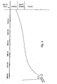
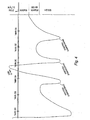
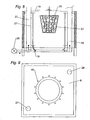
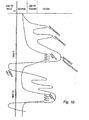
- FIG. 1 and 2 show a sauna cabin in plan view and side view; 3 shows the temperature sequence of a conventional sauna; 4 shows the temperature sequence of the sauna according to the invention; 5 shows a hot air cabin for a steam bath; Figures 6 to 9 show details of a hot air cabin for a stone bath; 10 shows the temperature sequence in a stone bath; 11 is a hot air cabin for a so-called Brechelbad. and FIG. 12 shows a detail of FIG. 11.
- Fig. 1 and 2 designate 1 a heater, 2 a seat for a visitor person, 3 a ceiling-side plate for a rotor R, which is driven by a motor 4 and air fins 7, which are covered on the ceiling side by an insulating layer 6, over which are located on a serving as ice spreader ejector preferably radially or obliquely outward ejection finger 5.
- 8 designates a chute for ice particles, wherein the ice ejection by a segment ring 9 with respect to the portion of the room, especially where there are no bathers, e.g. opposite the entrance door, can be screened.
- the motor-driven fan R on the ceiling D of the sauna cabin S leads after switching it to a short very intense heat stimulus by convection, which results from the energy output of the flowing hot air on the skin. After a short period, the fan is switched off again so that the temperature in the sauna room returns to normal. After a certain time, this process is repeated.
- the infusion 8 pieces of ice are thrown through the shaft, which are thrown by the ejection fingers 5 of the rotor R with the hot dry air in the room. This process is repeated a few times.
- intermediate staging Z is provided between the beginning and the infusion A. which partly by convective Hot air, partly by convective hot air and additionally when introducing the refrigerant, such as ice granules or snow, arise and cause a drop in temperature from hot to very warm, causing special stimuli in the body of the person to be treated.
- the injected ice particles or snowflakes have the advantage that they remain longer on the skin of the person being treated during the melting process and form when dissolved moisture that is mixed by the rotor R with the air present in the sauna room S air.
- the interior of the sauna cabin is made of poorly heat-conductive material, e.g. Fiberglass Resin (GRP), made, which is also moisture resistant.
- GRP Fiberglass Resin
- optical and / or acoustic signaling devices can be provided in the cabin, which draw the attention of the users of the cabin to the impending introduction of the refrigeration medium, in order not to cause a shock effect.
- the steam bath cabin shown in FIG. 5 has a rotor R with an impeller for air circulation, which is covered with an ice discharge disc 5 with ejection finger and an insulating layer 6 arranged underneath.
- the impeller 7 is driven by the motor 4 via the drive shaft 11, which is mounted on the ceiling side in the holding plate 3.
- the steam is introduced through a tube 10, which is secured with a cover 12.
- the use according to the invention of the hot air circulation which is temporarily coupled with an ice particle introduction through the chute 8, allows the swimmer to transfer heat from the humid-hot air flowing along the body Experience a warming climax. Shortly before the end, ice particles, snow or the like are introduced into the distribution system, which cause an extreme temperature counterpoint. The contact of the particles on the skin is so short that, if you did not know it, you can not tell with certainty whether the stimulus is warm or cold. The pieces of ice which may be present on the benches can still be manually used for refreshment rubbing.
- stones in a basket 21 which consists of iron od.
- a pivoting mechanism 22 by means of a drive device in an electric furnace 23 for heating the stones.
- the drive means for the pivot mechanism of the stone basket is indicated.
- the stones in the basket 21 are brought by the pivoting mechanism 22 in the opposite kettle 25, where the stones are quenched to generate steam, whereupon the basket 21 is returned to the electric furnace 23 for reheating the stones.
- the recirculated air for the electric furnace 23 or other heating device which emits radiant heat is conducted as fresh air through the suction port 31 and / or in the bottom region as circulating air through the suction port 30 to the electric furnace 23 via a motor-driven air fan 29.
- the air flow may pass through a pipe 26 which is preferably internally emanated and / or in the direction of the arrow P through an interior of the furnace, e.g. through an opening 27 '(Fig. 8) open pipe 27 are guided.
- the tube 26 may project upwardly above the electric furnace and serve as a protector through the overhanging part 20 'to prevent a bather from carelessly reaching into the oven area, as guests would not expect such hot air to flow up the furnace.
- This air flow can od interrupted or throttled by a deflector 28, throttle device. The like. To increase the temperature in the furnace interior.
- the basket 21 and the rod 21 'carrying it can be provided with a cover 20, which, as shown in FIG. 8, to a small angle is pivoted upward and can invest tightly on the furnace end wall 19.
- the heating elements of the electric furnace are designated.
- a rotor R is provided with air distributor blades 7 on the ceiling side, wherein through an over the cover side arranged shaft 8 ice granules, snow od. Like. Is introduced.
- Fig. 6 denotes an additional fan, which is only present and comes to fruition when the rotor R operated in place by motor 13 through this fan is, which blows the circulating air from the bath room through an intake 13 'to the rotor or the air distributor blades 6 in the direction of the arrow.
- the four waves on the summit indicate the slight temperature drop between two immersion phases.
- the wave peaks are generated by periodically switching off the fan.
- the temperature is up to the first peak to produce a first dry stimulus when the rotor is switched on
- the temperature drops after switching off the fan and then, when switched on again, rises to the second peak for the second dry stimulus, whereupon the rotor is switched off and the temperature drops then, when the rotor is switched on again, it will rise again to the next summit.
- the cold medium for example, ice granules, introduced so that the temperature, as shown, falls below a warm zone, after which the procedure can be repeated at most one or more times.
- the duration of the single cycle can be 5 minutes.
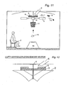
- FIG. 11 A further variant of the hot air cabin according to the invention is shown in FIG. 11, in which a so-called refractive bath is shown schematically, the name of which is derived from the use of broken, dried flax which is used as a treatment herb.
- This cabin also has on the ceiling side a driven by a motor 4 R rotor with air distributor blades 6, which is covered by an ejection disc with ejection finger 5th
- a preferably obliquely opening throw-in shaft 8 is provided above the rotor R, through which the cold medium, eg ice granules or snow, is thrown.
- a basket 21 is provided, in which, however, unlike the stone bath not Stones, but herbs are introduced, which are penetrated by the steam of a steam generator 14.
- the steam which is indicated by a swath 15, deprives the herbs of the active ingredient and brings him into the air circulation.
- the bathers 16 sit on treatment stations 17, which may be formed in a similar manner as the treatment stations of the hot air steam cabin described earlier.
Landscapes
- Health & Medical Sciences (AREA)
- Public Health (AREA)
- Epidemiology (AREA)
- Pain & Pain Management (AREA)
- Physical Education & Sports Medicine (AREA)
- Rehabilitation Therapy (AREA)
- Life Sciences & Earth Sciences (AREA)
- Animal Behavior & Ethology (AREA)
- General Health & Medical Sciences (AREA)
- Veterinary Medicine (AREA)
- Devices For Medical Bathing And Washing (AREA)
- Handcart (AREA)
- Ventilation (AREA)
- Direct Air Heating By Heater Or Combustion Gas (AREA)
Description
- Die Erfindung betrifft ein Verfahren nach dem Oberbegriff des Anspruches 1.
- Einen weiteren Gegenstand der Erfindung bildet eine Warmluftkabine zur Durchführung des Verfahrens.
Unter Warmluftkabinen sind eine Sauna, ein Dampfbad ein Brechelbad od. dgl. Anlagen zu verstehen, in welchen trockene und feuchte Luft bzw. Dampf dem menschlichen Körper zugeführt werden. In solchen Anlagen wird der Badegast einem Wärmereiz ausgesetzt, wonach eine Abkühlung in kalter Luft, Wasser oder Schnee erfolgt. Der wesentliche Nachteil dieser Anlagen ist vor allem ein hoher Kostenaufwand für die verbrauchte Energie unabhängig von der Gästefrequenz. Ein weiterer Nachteil,dieser Anlagen war, dass thermophysikalische Ressourcen nicht oder nicht ausreichend genutzt wurden, bzw. dass die Nutzung nicht gesichert zur richtigen Zeit erfolgte, was mit einer Schmälerung des beabsichtigten Effektes verbunden war. - Durch die
EP 779 067 - Die
DE 199 30 652 A , gegenüber welcher Anspruch 1 abgegrenzt ist, offenbart ein Verfahren zum Betrieb einer Warm- oder Heißluftkabine unter Anwendung eines Kältemittels in Form von Wasser, welches verdampft wird, wobei die zum Verdampfen nötige Verdampfungswärme zur Erzeugung von Reizen im menschlichen Körper dient. - Durch die
EP 943 308 - Schließlich ist es bekannt geworden, Eis in Eimern in die Warmluftkabine einzubringen, um den Gästen die Möglichkeit zu bieten, sich mit dem Eis den Körper abzureiben. Bei dieser Art der Anwendung konnten nur Brust und Beine behandelt werden, während der Rücken, welcher am wichtigsten gewesen wäre, unbehandelt blieb.
- Die vorliegende Erfindung hat zur Aufgabe, Maßnahmen zur Vermeidung der Nachteile der bekannten Anlagen zu schaffen und wesentlich bessere Behandlungsergebnisse zu erzielen. Diese Aufgabe wird durch Anspruch 1 gelöst. Als Kältemittel können beispielsweise geringe Mengen von Schnee, Eisflocken, Würfeleisgranulat od. dgl., eingebracht bzw. eingeführt werden, so dass ein schwankender Wärmeablauf entsteht.
- Durch die Maßnahmen nach Anspruch 2 werden die angestrebten Reizeffekte verstärkt.
- Die zur Durchführung des Verfahrens dienende Anlage besitzt erfindungsgemäß die Merkmale nach Anspruch 3.
- Erfindungsgemäß ist die Einrichtung zur Zufuhr von Kältemitteln im Bereich der Luftumwälzeinrichtung in Form eines deckenseitig angeordneten Rotors angeordnet.
- Die
EP 246 179 A DE 201 02 686 U eine Sauna mit einer Zufuhr von Stückeis, wobei ein Zerkleinerer vorgesehen ist. Keiner der beiden Dokumente zeigt die Maßnahme, dass die Einrichtung zur Zufuhr von Kältemitteln im Bereich der Luftumwälzeinrichtung angeordnet ist. Dadurch wird eine platzsparende Anordnung erzielt. - Durch die Maßnahme nach Anspruch 4 wird eine günstige Verteilung des Kältemittels erzielt.
- Die Maßnahme nach Anspruch 5 dient zum Schutz der Saunagäste vor unangenehmen Kälteschocks.
- Die Maßnahme nach Anspruch 6 kennzeichnet eine zweckmäßige Weiterausbildung der Wärmekabine.
- In der Folge werden Ausführungsbeispiele für einige Arten von Warmluftkabinen erläutert. Es zeigen: Die Fig. 1 und 2 eine Saunakabine in Draufsicht und Seitenansicht; Fig. 3 den Temperaturablauf einer üblichen Sauna; Fig. 4 den Temperaturablauf der erfindungsgemäßen Sauna; Fig. 5 eine Warmluftkabine für ein Dampfbad; die Fig. 6 bis 9 Einzelheiten einer Warmluftkabine für ein Steinbad; Fig. 10 den Temperaturablauf in einem Steinbad; Fig. 11 eine Warmluftkabine für ein sogenanntes Brechelbad; und Fig. 12 ein Detail der Fig. 11.
- In den Fig. 1 und 2 bezeichnen 1 einen Saunaofen, 2 eine Sitzgelegenheit für eine Besucherperson, 3 eine deckenseitige Halteplatte für einen Rotor R, welcher von einem Motor 4 angetrieben wird und Luftlamellen 7 aufweist, die deckenseitig von einer Isolierschicht 6 abgedeckt sind, über der sich auf einer als Eisverteiler dienenden Auswurfscheibe vorzugsweise radial oder schräg nach außen gerichtete Auswurffinger 5 befinden. Mit 8 ist ein Einwurfschacht für Eisteilchen bezeichnet, wobei der Eisauswurf durch einen Segmentring 9 gegenüber dem Teilbereich des Raumes, insbesondere dort wo keine Badegäste sind, z.B. gegenüber der Eingangstüre, abgeschirmt werden kann.
- Der motorbetriebene Ventilator R an der Decke D der Saunakabine S führt nach Einschaltung desselben zu einem kurzen sehr intensiven Wärmereiz durch Konvektion, welche durch die Energieabgabe der an der Haut strömenden Warmluft entsteht. Nach einer kurzen Laufzeit wird der Ventilator wieder ausgeschaltet, so dass sich die Temperatur in der Saunakabine wieder normalisiert. Nach einer bestimmten Zeit wird dieser Vorgang wiederholt. Während des sogenannten Überwärmungshöhepunkts, beispielsweise des Aufgusses, werden durch den Schacht 8 Eisstückchen eingeworfen, welche von den Auswurffingern 5 des Rotors R mit der heißen trockenen Luft in den Raum geschleudert werden. Dieser Ablauf wird einige Male wiederholt.
- Während sich beim bisherigen Saunabetrieb, wie das Diagramm in Fig. 3 zeigt, bis zum manuellen Aufguss in Punkt A ein nahezu linearer Wärmeanstieg entwickelt hat, sind beim erfindungsgemäßen Ablauf, wie Fig. 4 zeigt, zwischen Beginn und dem Aufguss A Zwischenreihstufen Z vorgesehen, welche teils durch konvektive Heißluft, teils durch konvektive Heißluft und zusätzlich beim Einbringen des Kältemittels, z.B. von Eisgranulat oder Schnee, entstehen und ein Absinken der Temperatur von heiß auf sehr warm bewirken, wodurch im Körper der behandelnden Person besondere Reize entstehen.
- Die eingeblasenen Eisteilchen oder Schneeflocken haben den Vorteil, dass sie auf der Haut der behandelnden Personen während des Schmelzvorganges länger verbleiben und bilden beim Auflösen Feuchtigkeit, die durch den Rotor R mit der im Saunaraum S vorhandenen Luft vermengt wird.
- Vorzugsweise wird die Innenausstattung der Saunakabine, insbesondere die Sitzgelegenheiten, aus schlecht wärmeleitendem Material, z.B. Glasfaserkunstharz (GFK), hergestellt, welches auch feuchtigkeitsbeständig ist. Dadurch wird auch ein Feuerschutz erzielt.
- Im Rahmen der Erfindung können in der Kabine optische und bzw. oder akustische Signaleinrichtungen vorgesehen sein, welche die Benützer der Kabine auf das bevorstehende Einbringen des Kältemediums aufmerksam machen, um keine Schockwirkung zu verursachen.
- Die in Fig. 5 dargestellte Dampfbadkabine besitzt ähnlich wie die Saunakabine nach den Fig. 1 und 2 einen Rotor R mit einem Luftverteilerlamellen-aufweisenden 7 Flügelrad für die Luftumwälzung, welches mit einer Eisauswurfscheibe 5 mit Auswurffinger sowie einer darunter angeordneten Isolierschicht 6 abgedeckt ist. Das Flügelrad 7 wird durch den Motor 4 über die Antriebswelle 11 angetrieben, welche deckenseitig in der Halteplatte 3 gelagert ist.
- Der Dampf wird durch ein Rohr 10 eingebracht, welches mit einer Abdeckung 12 abgesichert ist.
- Der erfindungsgemäße Einsatz der Heißluftumwälzung, die zeitweise mit einer Eisteilcheneinbringung durch den Einwurfschacht 8 gekoppelt ist, lässt den Badegast durch die Wärmeübertragung aus der entlang des Körpers strömenden feucht-heißen Luft einen Überwärmungs-Höhepunkt erleben. Kurz vor Ende werden Eis-Teilchen, Schnee od. dgl. in die Verteileranlage eingebracht, welche einen extremen Temperaturkontrapunkt bewirken. Die Berührung der Teilchen auf der Haut ist so kurz, dass, wenn man es nicht wüsste, nicht mit Sicherheit erkannt werden kann, ob der Reiz warm oder kalt ist. Die auf den Sitzbänken nachher allenfalls befindlichen Eisstücke können händisch noch für Erfrischungsabreibungen verwendet werden.
- Bei einem Steinbad werden, wie die Fig. 6 bis 9 zeigen, Steine in einen Korb 21, welcher aus Eisen od. dgl. besteht, eingelegt und mit einem Schwenkmechanismus 22 mittels einer Antriebseinrichtung in einen Elektroofen 23 zum Erwärmen der Steine eingebracht. Mit 24 ist die Antriebseinrichtung für den Schwenkmechanismus des Steinkorbes angedeutet. Hierauf werden die Steine im Korb 21 durch den Schwenkmechanismus 22 in den gegenüber befindlichen Wasserkessel 25 gebracht, wo die Steine zur Dampfentwicklung abgeschreckt werden, worauf der Korb 21 wieder in den Elektroofen 23 zum Nacherwärmen der Steine zurückgeführt wird.
- Die zur Umwälzung gebrachte Luft für den Elektroofen 23 oder eine andere Heizeinrichtung, welche Strahlungswärme abgibt, wird als Frischluft durch die Ansaugöffnung 31 und bzw. oder im Bodenbereich als Umluft durch die Ansaugöffnung 30 zum Elektroofen 23 über einen motorgetriebenen Luftventilator 29 geführt. Der Luftstrom kann durch ein vorzugsweise innen ausschamottiertes Rohr 26 und bzw. oder in Richtung des Pfeiles P durch ein in das Ofeninnere z.B. durch einen Durchbruch 27' (Fig. 8) offenes Rohr 27 geführt werden. Das Rohr 26 kann den Elektroofen nach oben überragen und durch den überragenden Teil 20' als Schutzeinrichtung dienen, um zu verhindern, dass ein Badegast nicht unvorsichtigerweise in den Ofenbereich greift, weil Gäste nicht vermuten würden, dass so heiße Luft vom Ofen nach oben strömt. Dieser Luftstrom kann durch eine Ablenkeinrichtung 28, Drosseleinrichtung od. dgl. unterbrochen oder gedrosselt werden, um die Temperatur im Ofeninneren zu steigern.
- Der Korb 21 bzw. die ihn tragende Stange 21' kann mit einem Deckel 20 versehen sein, welcher, wie Fig. 8 zeigt, um einen kleinen Winkel nach oben schwenkbar ist und sich an der Ofenabschlusswand 19 dicht anlegen kann.
- Mit 18 sind die Heizstäbe des Elektroofens bezeichnet.
- Ähnlich wie beim Saunabetrieb ist deckenseitig ein Rotor R mit Luftverteilerlamellen 7 vorgesehen, wobei durch einen darüber deckenseitig angeordneten Schacht 8 Eisgranulat, Schnee od. dgl. eingebracht wird.
- Im Steinbad gibt es keine fixierten Badezyklen wie in der Sauna. Die Badegäste kommen und gehen wie es ihnen beliebt ist. Wenn ein Badegast zu Beginn der Aufheizzeit das Steinbad betritt, dauert es 4 bis 5 Minuten, bis es zu einem echten Wärmereiz kommt.
- Nach einer kurzen Wartezeit wird durch die Ansaugöffnung 31 kalte unverbrauchte Frischluft von außen und bzw. oder durch die Ansaugöffnung 30 im Bodenbereich warme Raumluft durch den motorisch angetriebenen Ventilator 29 in den Ofen 23 eingeblasen.
Die Luft wird, nachdem sie erhitzt wurde, in Richtung des Pfeiles B durch das, wie ein Wärmetauscher wirkendes Rohr 26 oder offen über den Innenraum des Elektroofens 23 in Richtung zur Decke geführt, wo sie mit der übrigen Luft vermengt wird. Der motorisch angetriebene Rotor R wird nach einem Programm ein- und ausgeschaltet. Beim Einschalten des Rotors R wird die Luft nach außen und an der Wand nach unten gedrückt. Wenn der Rotor ausgeschaltet wird, normalisiert sich das Klima wieder im Baderaum. Wenn der Rotor wieder eingeschaltet wird, kommt es beim Eintauchen der heißen Steine in den Wasserkessel 25 zu einem Höhepunkt der Erwärmung. Der dabei entstehende Dampf schießt nach oben, wodurch sich die im Deckenbereich aufgestaute trockene und heiße Luft mit dem Wasserdampf vom Eintauchvorgang vermischt. Gegen Ende der Rotorlaufzeit werden über den Einwurfschacht 8 an der Raumdecke kleine Eisstückchen, Schnee od. dgl. eingeworfen und von der Eisverteilerscheibe 5 in den Baderaum geschleudert. - In Fig. 6 ist mit 13 ein zusätzlicher Ventilator bezeichnet, welcher nur dann vorhanden ist und zum Tragen kommt, wenn der Rotor R an Stelle motorisch durch diesen Ventilator 13 betrieben wird, welcher die Umluft aus dem Baderaum durch einen Ansaugstutzen 13' zum Rotor bzw. den Luftverteilerlamellen 6 in Richtung des eingezeichneten Pfeiles bläst.
- In Fig. 10 ist der Temperaturverlauf in einem Steinbad wie er bisher erfolgt ist, mit strichlierter Linie und nach dem erfindungsgemäßen Verfahren mit voll ausgezogener Linie gezeichnet.
- Die vier Wellen auf dem Gipfel deuten den leichten Temperaturabfall zwischen zwei Eintauchphasen an.
- Gegenüber dieser Behandlungsmethode werden die Wellengipfel durch periodisches Abschalten des Ventilators erzeugt. Steigt beim eingeschalteten Rotor die Temperatur bis zum ersten Gipfel zur Erzeugung eines ersten Trockenreizes, sinkt nach dem Abschalten des Ventilators die Temperatur, um dann beim neuerlichen Einschalten zum zweiten Gipfel für den zweiten Trockenreiz anzusteigen, worauf der Rotor abgeschaltet wird und die Temperatur fällt, um dann beim neuerlichen Einschalten des Rotors wiederum zu steigen bis zum weiteren Gipfel. Zwischen diesen beiden Phasen wird das Kältemedium, zum Beispiel Eisgranulat, eingebracht, so dass die Temperatur, wie dargestellt, unter eine warme Zone fällt, worauf die Vorgangsweise allenfalls ein- oder mehrmals wiederholt werden kann. Die Dauer des einzelnen Zyklus kann beispielsweise 5 Minuten ausmachen.
- Eine weitere Variante der erfindungsgemäßen Warmluftkabine zeigt Fig. 11, in welcher ein sogenanntes Brechelbad schematisch dargestellt ist, dessen Name von der Verwendung von gebrochenem, getrocknetem Flachs abgeleitet wird, das als Behandlungskräuter verwendet wird. Diese Kabine besitzt ebenfalls deckenseitig einen durch einen Motor 4 angetriebenen Rotor R mit Luftverteilerlamellen 6, die durch eine Auswurfscheibe mit Auswurffinger 5. abgedeckt ist. In gleicher Weise wie bei den früheren Warm- bzw. Heißluftkabinen ist über dem Rotor R ein vorzugsweise schräg einmündender Einwurfschaft 8 vorgesehen, durch welchen das Kältemedium, z.B. Eisgranulat oder Schnee, eingeworfen wird. In diesem Bad ist ähnlich wie beim Steinbad ein Korb 21 vorgesehen, in welchem jedoch zum Unterschied zum Steinbad nicht Steine, sondern Kräuter eingebracht sind, welche vom Dampf eines Dampferzeugers 14 durchsetzt werden. Der Dampf, welcher durch eine Schwade 15 angedeutet ist, entzieht den Kräutern den Wirkstoff und bringt ihn in die Luftzirkulation ein. Die Badegäste 16 sitzen auf Behandlungsplätzen 17, welche in ähnlicher Weise wie die Behandlungsplätze der früher beschriebenen Warmluftdampfbadkabinen ausgebildet sein können.
Claims (6)
- Verfahren zum Betrieb einer Warm- oder Heißluftkabine unter Anwendung eines Kältemittels zur Erzeugung von Reizen im menschlichen Körper, dadurch gekennzeichnet, dass die Warm- bzw. Heißluft in einer Kabine deckenseitig umgewälzt und in Zeitabständen beruhigt und das Kältemittel in die strömende Warm- bzw. Heißluft deckenseitig eingebracht wird.
- Verfahren nach Anspruch 1, dadurch gekennzeichnet, dass während des Aufgusses Zwischenstufen vorgesehen sind, in welchen durch Abschalten eines die Luftumwälzung deckenseitig bewirkenden Ventilators eine zeitweise Beruhigung der Luftumwälzung erfolgt, während welcher ein zusätzliches Kältemittel eingebracht wird (Fig. 4).
- Warmluftkabine zur Durchführung des Verfahrens nach Anspruch 1, dadurch gekennzeichnet, dass neben einer Heizeinrichtung und einer Luftumwälzeinrichtung in Form eines Rotors (R) eine Einrichtung zum Einbringen von Kältemitteln in die strömende Warm- bzw. Heißluft vorgesehen ist, welche deckenseitig im Bereich des Rotors (R) angeordnet ist, wobei eine Einrichtung zur Unterbrechung der Heizluftumwälzungvorgesehen ist.
- Warmluftkabine nach Anspruch 3, dadurch gekennzeichnet, dass der Rotor (R) durch eine Auswurfscheibe für eingebrachtes Kältemittel in Form von Schnee, Eisflocken, Würfeleisgranulat od. dgl. mit nach außen gerichteten, vorzugsweise radial und bzw. oder schräg dazu verlaufenden Auswurffingern (5) abgedeckt ist.
- Warmluftkabine nach Anspruch 4, dadurch gekennzeichnet, dass die Auswurfscheibe mit den Auswurffingern (5) dort, wo keine Gäste sitzen, durch einen Segmentring (9) abgeschirmt ist.
- Warmluftkabine nach mindestens einem der Ansprüche 3 bis 5 mit einer als Elektroofen ausgebildeten Heizeinrichtung, welche bodenseitig einen Frischlufteinlass aufweist, dadurch gekennzeichnet, dass seitlich der Ofenwand mindestens ein mit Schamotte ausgekleidetes Rohr (26), ein Kanalschacht od. dgl. vorgesehen ist, welches bzw. welcher an einer Abschlusswand (19) des Ofens (23) in den Kabinenraum mündet.
Applications Claiming Priority (3)
| Application Number | Priority Date | Filing Date | Title |
|---|---|---|---|
| AT4922003 | 2003-03-28 | ||
| AT0049203A AT412615B (de) | 2003-03-28 | 2003-03-28 | Warmluftkabine und verfahren zum betrieb derselben |
| PCT/AT2004/000107 WO2004084791A1 (de) | 2003-03-28 | 2004-03-23 | Verfahren zum betrieb einer warm- oder heissluftkabine sowie warmluftkabine zur durchführung des verfahrens |
Publications (2)
| Publication Number | Publication Date |
|---|---|
| EP1608304A1 EP1608304A1 (de) | 2005-12-28 |
| EP1608304B1 true EP1608304B1 (de) | 2007-07-04 |
Family
ID=33034706
Family Applications (1)
| Application Number | Title | Priority Date | Filing Date |
|---|---|---|---|
| EP04722506A Expired - Lifetime EP1608304B1 (de) | 2003-03-28 | 2004-03-23 | Verfahren zum betrieb einer warm- oder heissluftkabine sowie warmluftkabine zur durchführung des verfahrens |
Country Status (5)
| Country | Link |
|---|---|
| US (1) | US20060184077A1 (de) |
| EP (1) | EP1608304B1 (de) |
| AT (2) | AT412615B (de) |
| DE (1) | DE502004004238D1 (de) |
| WO (1) | WO2004084791A1 (de) |
Families Citing this family (8)
| Publication number | Priority date | Publication date | Assignee | Title |
|---|---|---|---|---|
| SE528810C2 (sv) | 2005-06-13 | 2007-02-20 | Ulf Samuelsson | En anordning för aktiv temperaturutjämning i ett basturum |
| EP2092926A1 (de) * | 2008-01-24 | 2009-08-26 | Franz Hirz | Zusatzvorrichtung für ein Heizgerät |
| DE202010001507U1 (de) * | 2010-01-29 | 2011-06-01 | Buck-Heitmann, Petra, 22397 | Vorrichtung zum Abkühlen von Personen |
| DE202010003262U1 (de) * | 2010-03-08 | 2011-08-26 | Klafs Gmbh & Co. Kg | Saunaofen |
| ITVR20130292A1 (it) * | 2013-12-23 | 2015-06-24 | Technoalpin Holding S P A | Apparato di innevamento per locali chiusi |
| CN105877992B (zh) * | 2016-04-06 | 2018-10-30 | 苏州蒂珀克制冷科技有限公司 | 超冷桑拿装置 |
| DE102017120177B3 (de) * | 2017-09-01 | 2018-08-09 | Kurland GmbH | Schnee- und/oder Eisdusche |
| JP7537037B1 (ja) | 2024-01-17 | 2024-08-20 | Tis株式会社 | 室内暖房設備、サウナ、及び室内暖房方法 |
Family Cites Families (11)
| Publication number | Priority date | Publication date | Assignee | Title |
|---|---|---|---|---|
| US1564552A (en) * | 1921-10-17 | 1925-12-08 | Theodore R N Gerdes | Apparatus for therapeutic treatment |
| US3051180A (en) * | 1954-12-03 | 1962-08-28 | Richard Magnus Kindal | Body tempering apparatus |
| DE2515188A1 (de) * | 1973-02-24 | 1976-10-21 | Jacob Demmer | Sauna-duschkombination |
| US4044772A (en) * | 1976-03-29 | 1977-08-30 | Benjamin Schloss | Apparatus for cardiovascular conditioning and other physiological purposes |
| DE3615760A1 (de) * | 1986-05-10 | 1987-11-12 | Herbert Thesen | Raumzelle fuer eine sauna-anlage |
| DE19546392C1 (de) * | 1995-12-12 | 1997-05-28 | Paul Haslauer | Warmluft-Dampfbad-Kabine |
| DE19645077C1 (de) * | 1996-10-31 | 1997-10-16 | Paul Haslauer | Behandlungsanlage zur Durchführung eines Wannen- und/oder Dampfbades |
| DE19812075C2 (de) * | 1998-03-19 | 2000-07-06 | Paul Haslauer | Verfahren zur Erzeugung und/oder zur Verabreichung von Temperatur- und/oder mechanischen Reizen sowie zugehörige Vorrichtung |
| DE19930652A1 (de) * | 1999-07-02 | 2001-01-04 | Saunalux Gmbh | Umluftheizungsanlage für einen Saunaraum |
| ES2550999T3 (es) * | 1999-08-09 | 2015-11-13 | Daikin Industries, Ltd. | Protector de ventilador de una unidad de soplado y aire acondicionado |
| DE20102686U1 (de) * | 2001-02-15 | 2001-04-19 | Röger GmbH, 74523 Schwäbisch Hall | Zusatzeinrichtung für eine Sauna, ein thermisches Bad o.dgl. mit einem Stückeiserzeuger |
-
2003
- 2003-03-28 AT AT0049203A patent/AT412615B/de not_active IP Right Cessation
-
2004
- 2004-03-23 DE DE502004004238T patent/DE502004004238D1/de not_active Expired - Lifetime
- 2004-03-23 US US10/551,213 patent/US20060184077A1/en not_active Abandoned
- 2004-03-23 WO PCT/AT2004/000107 patent/WO2004084791A1/de active IP Right Grant
- 2004-03-23 EP EP04722506A patent/EP1608304B1/de not_active Expired - Lifetime
- 2004-03-23 AT AT04722506T patent/ATE366100T1/de active
Also Published As
| Publication number | Publication date |
|---|---|
| ATE366100T1 (de) | 2007-07-15 |
| EP1608304A1 (de) | 2005-12-28 |
| AT412615B (de) | 2005-05-25 |
| ATA4922003A (de) | 2004-10-15 |
| US20060184077A1 (en) | 2006-08-17 |
| WO2004084791A1 (de) | 2004-10-07 |
| DE502004004238D1 (de) | 2007-08-16 |
Similar Documents
| Publication | Publication Date | Title |
|---|---|---|
| DE69407619T2 (de) | Gerät zur wärmebehandlung eines nahrungsmittels | |
| EP0383366B1 (de) | Verfahren zum Dampf-Garen von Nahrungsmitteln | |
| EP0226936B1 (de) | Verfahren und Vorrichtung zum thermischen Polymerisieren von Kunststoffen für Dentalzwecke | |
| EP0436703B1 (de) | Verfahren und einrichtung zur zubereitung von speisen | |
| EP1608304B1 (de) | Verfahren zum betrieb einer warm- oder heissluftkabine sowie warmluftkabine zur durchführung des verfahrens | |
| CH497163A (de) | Trockengerät | |
| DE2541374A1 (de) | Garmachverfahren und -vorrichtung | |
| EP1010384B1 (de) | Gargerät und Verfahren zur Wärmebehandlung eines Gargutes mit Dampf | |
| DE69808647T2 (de) | Gerät zur wärmebehandlung einer bestimmten speise | |
| EP0044898A1 (de) | Verfahren und Einrichtung zum raschen Trocknen insbesondere von Fellen | |
| EP1936285B1 (de) | Gargerät mit Wärmespeicher und Verfahren zu dessen Betrieb | |
| EP0894460B1 (de) | Dampfgarofen | |
| EP2092926A1 (de) | Zusatzvorrichtung für ein Heizgerät | |
| EP4185174A1 (de) | Vorrichtung zum erhitzen und/oder garen von lebensmitteln | |
| EP2626054A1 (de) | Warmluft- und/oder Dampfbadvorrichtung | |
| DE2711222C2 (de) | Trocknungseinrichtung für Tiere | |
| DE3210172C2 (de) | ||
| DE3941220A1 (de) | Beweglicher warmlufttrockner zum abtrocknen des menschlichen koerpers | |
| DE7604014U1 (de) | Trocknungsgeraet fuer tiere, insbesondere fuer hunde nach dem waschen | |
| DE2716721A1 (de) | Vorrichtung zum waschen und wahlweisen trocknen von waesche o.dgl. | |
| DE19930652A1 (de) | Umluftheizungsanlage für einen Saunaraum | |
| DE2160571B1 (de) | Saunaofen | |
| DE102006011028A1 (de) | Verfahren zur Steuerung eines Mikrowellenofens | |
| DE4341570A1 (de) | Verfahren und Vorrichtung zum Rösten grüner Kaffeebohnen | |
| DE362256C (de) | Kaltluftmaschine |
Legal Events
| Date | Code | Title | Description |
|---|---|---|---|
| PUAI | Public reference made under article 153(3) epc to a published international application that has entered the european phase |
Free format text: ORIGINAL CODE: 0009012 |
|
| 17P | Request for examination filed |
Effective date: 20050912 |
|
| AK | Designated contracting states |
Kind code of ref document: A1 Designated state(s): AT BE BG CH CY CZ DE DK EE ES FI FR GB GR HU IE IT LI LU MC NL PL PT RO SE SI SK TR |
|
| AX | Request for extension of the european patent |
Extension state: AL LT LV MK |
|
| DAX | Request for extension of the european patent (deleted) | ||
| 17Q | First examination report despatched |
Effective date: 20060901 |
|
| GRAP | Despatch of communication of intention to grant a patent |
Free format text: ORIGINAL CODE: EPIDOSNIGR1 |
|
| GRAS | Grant fee paid |
Free format text: ORIGINAL CODE: EPIDOSNIGR3 |
|
| GRAA | (expected) grant |
Free format text: ORIGINAL CODE: 0009210 |
|
| AK | Designated contracting states |
Kind code of ref document: B1 Designated state(s): AT BE BG CH CY CZ DE DK EE ES FI FR GB GR HU IE IT LI LU MC NL PL PT RO SE SI SK TR |
|
| REG | Reference to a national code |
Ref country code: GB Ref legal event code: FG4D Free format text: NOT ENGLISH |
|
| REG | Reference to a national code |
Ref country code: CH Ref legal event code: EP |
|
| REG | Reference to a national code |
Ref country code: IE Ref legal event code: FG4D Free format text: LANGUAGE OF EP DOCUMENT: GERMAN |
|
| REF | Corresponds to: |
Ref document number: 502004004238 Country of ref document: DE Date of ref document: 20070816 Kind code of ref document: P |
|
| GBT | Gb: translation of ep patent filed (gb section 77(6)(a)/1977) |
Effective date: 20071008 |
|
| REG | Reference to a national code |
Ref country code: GR Ref legal event code: EP Ref document number: 20070403013 Country of ref document: GR |
|
| NLV1 | Nl: lapsed or annulled due to failure to fulfill the requirements of art. 29p and 29m of the patents act | ||
| PG25 | Lapsed in a contracting state [announced via postgrant information from national office to epo] |
Ref country code: BG Free format text: LAPSE BECAUSE OF FAILURE TO SUBMIT A TRANSLATION OF THE DESCRIPTION OR TO PAY THE FEE WITHIN THE PRESCRIBED TIME-LIMIT Effective date: 20071004 Ref country code: SI Free format text: LAPSE BECAUSE OF FAILURE TO SUBMIT A TRANSLATION OF THE DESCRIPTION OR TO PAY THE FEE WITHIN THE PRESCRIBED TIME-LIMIT Effective date: 20070704 Ref country code: ES Free format text: LAPSE BECAUSE OF FAILURE TO SUBMIT A TRANSLATION OF THE DESCRIPTION OR TO PAY THE FEE WITHIN THE PRESCRIBED TIME-LIMIT Effective date: 20071015 Ref country code: PT Free format text: LAPSE BECAUSE OF FAILURE TO SUBMIT A TRANSLATION OF THE DESCRIPTION OR TO PAY THE FEE WITHIN THE PRESCRIBED TIME-LIMIT Effective date: 20071204 Ref country code: NL Free format text: LAPSE BECAUSE OF FAILURE TO SUBMIT A TRANSLATION OF THE DESCRIPTION OR TO PAY THE FEE WITHIN THE PRESCRIBED TIME-LIMIT Effective date: 20070704 Ref country code: FI Free format text: LAPSE BECAUSE OF FAILURE TO SUBMIT A TRANSLATION OF THE DESCRIPTION OR TO PAY THE FEE WITHIN THE PRESCRIBED TIME-LIMIT Effective date: 20070704 |
|
| EN | Fr: translation not filed | ||
| PG25 | Lapsed in a contracting state [announced via postgrant information from national office to epo] |
Ref country code: PL Free format text: LAPSE BECAUSE OF FAILURE TO SUBMIT A TRANSLATION OF THE DESCRIPTION OR TO PAY THE FEE WITHIN THE PRESCRIBED TIME-LIMIT Effective date: 20070704 |
|
| REG | Reference to a national code |
Ref country code: IE Ref legal event code: FD4D |
|
| PG25 | Lapsed in a contracting state [announced via postgrant information from national office to epo] |
Ref country code: DK Free format text: LAPSE BECAUSE OF FAILURE TO SUBMIT A TRANSLATION OF THE DESCRIPTION OR TO PAY THE FEE WITHIN THE PRESCRIBED TIME-LIMIT Effective date: 20070704 |
|
| PLBE | No opposition filed within time limit |
Free format text: ORIGINAL CODE: 0009261 |
|
| STAA | Information on the status of an ep patent application or granted ep patent |
Free format text: STATUS: NO OPPOSITION FILED WITHIN TIME LIMIT |
|
| PG25 | Lapsed in a contracting state [announced via postgrant information from national office to epo] |
Ref country code: IE Free format text: LAPSE BECAUSE OF FAILURE TO SUBMIT A TRANSLATION OF THE DESCRIPTION OR TO PAY THE FEE WITHIN THE PRESCRIBED TIME-LIMIT Effective date: 20070704 Ref country code: CZ Free format text: LAPSE BECAUSE OF FAILURE TO SUBMIT A TRANSLATION OF THE DESCRIPTION OR TO PAY THE FEE WITHIN THE PRESCRIBED TIME-LIMIT Effective date: 20070704 Ref country code: SK Free format text: LAPSE BECAUSE OF FAILURE TO SUBMIT A TRANSLATION OF THE DESCRIPTION OR TO PAY THE FEE WITHIN THE PRESCRIBED TIME-LIMIT Effective date: 20070704 |
|
| 26N | No opposition filed |
Effective date: 20080407 |
|
| PG25 | Lapsed in a contracting state [announced via postgrant information from national office to epo] |
Ref country code: SE Free format text: LAPSE BECAUSE OF FAILURE TO SUBMIT A TRANSLATION OF THE DESCRIPTION OR TO PAY THE FEE WITHIN THE PRESCRIBED TIME-LIMIT Effective date: 20071004 Ref country code: RO Free format text: LAPSE BECAUSE OF FAILURE TO SUBMIT A TRANSLATION OF THE DESCRIPTION OR TO PAY THE FEE WITHIN THE PRESCRIBED TIME-LIMIT Effective date: 20070704 |
|
| PG25 | Lapsed in a contracting state [announced via postgrant information from national office to epo] |
Ref country code: FR Free format text: LAPSE BECAUSE OF FAILURE TO SUBMIT A TRANSLATION OF THE DESCRIPTION OR TO PAY THE FEE WITHIN THE PRESCRIBED TIME-LIMIT Effective date: 20080229 |
|
| BERE | Be: lapsed |
Owner name: HASLAUER, PAUL Effective date: 20080331 |
|
| PG25 | Lapsed in a contracting state [announced via postgrant information from national office to epo] |
Ref country code: MC Free format text: LAPSE BECAUSE OF NON-PAYMENT OF DUE FEES Effective date: 20080331 |
|
| REG | Reference to a national code |
Ref country code: CH Ref legal event code: PL |
|
| PG25 | Lapsed in a contracting state [announced via postgrant information from national office to epo] |
Ref country code: LI Free format text: LAPSE BECAUSE OF NON-PAYMENT OF DUE FEES Effective date: 20080331 Ref country code: CH Free format text: LAPSE BECAUSE OF NON-PAYMENT OF DUE FEES Effective date: 20080331 Ref country code: EE Free format text: LAPSE BECAUSE OF FAILURE TO SUBMIT A TRANSLATION OF THE DESCRIPTION OR TO PAY THE FEE WITHIN THE PRESCRIBED TIME-LIMIT Effective date: 20070704 |
|
| PG25 | Lapsed in a contracting state [announced via postgrant information from national office to epo] |
Ref country code: BE Free format text: LAPSE BECAUSE OF NON-PAYMENT OF DUE FEES Effective date: 20080331 |
|
| PGFP | Annual fee paid to national office [announced via postgrant information from national office to epo] |
Ref country code: GB Payment date: 20090325 Year of fee payment: 6 Ref country code: GR Payment date: 20090317 Year of fee payment: 6 |
|
| PG25 | Lapsed in a contracting state [announced via postgrant information from national office to epo] |
Ref country code: CY Free format text: LAPSE BECAUSE OF FAILURE TO SUBMIT A TRANSLATION OF THE DESCRIPTION OR TO PAY THE FEE WITHIN THE PRESCRIBED TIME-LIMIT Effective date: 20070704 |
|
| PG25 | Lapsed in a contracting state [announced via postgrant information from national office to epo] |
Ref country code: LU Free format text: LAPSE BECAUSE OF NON-PAYMENT OF DUE FEES Effective date: 20080323 Ref country code: HU Free format text: LAPSE BECAUSE OF FAILURE TO SUBMIT A TRANSLATION OF THE DESCRIPTION OR TO PAY THE FEE WITHIN THE PRESCRIBED TIME-LIMIT Effective date: 20080105 |
|
| PG25 | Lapsed in a contracting state [announced via postgrant information from national office to epo] |
Ref country code: TR Free format text: LAPSE BECAUSE OF FAILURE TO SUBMIT A TRANSLATION OF THE DESCRIPTION OR TO PAY THE FEE WITHIN THE PRESCRIBED TIME-LIMIT Effective date: 20070704 |
|
| GBPC | Gb: european patent ceased through non-payment of renewal fee |
Effective date: 20100323 |
|
| PG25 | Lapsed in a contracting state [announced via postgrant information from national office to epo] |
Ref country code: GR Free format text: LAPSE BECAUSE OF NON-PAYMENT OF DUE FEES Effective date: 20101004 Ref country code: GB Free format text: LAPSE BECAUSE OF NON-PAYMENT OF DUE FEES Effective date: 20100323 |
|
| REG | Reference to a national code |
Ref country code: DE Ref legal event code: R082 Ref document number: 502004004238 Country of ref document: DE Representative=s name: WEICKMANN & WEICKMANN, DE |
|
| PGFP | Annual fee paid to national office [announced via postgrant information from national office to epo] |
Ref country code: IT Payment date: 20150324 Year of fee payment: 12 |
|
| REG | Reference to a national code |
Ref country code: DE Ref legal event code: R081 Ref document number: 502004004238 Country of ref document: DE Owner name: REITERALM G.M.B.H., DE Free format text: FORMER OWNER: HASLAUER, PAUL, SALZBURG, AT Effective date: 20150402 Ref country code: DE Ref legal event code: R082 Ref document number: 502004004238 Country of ref document: DE Representative=s name: PATENTANWAELTE WEICKMANN & WEICKMANN, DE Effective date: 20150402 Ref country code: DE Ref legal event code: R082 Ref document number: 502004004238 Country of ref document: DE Representative=s name: PATENTANWAELTE WEICKMANN & WEICKMANN, DE Effective date: 20150507 Ref country code: DE Ref legal event code: R082 Ref document number: 502004004238 Country of ref document: DE Representative=s name: WEICKMANN & WEICKMANN PATENTANWAELTE - RECHTSA, DE Effective date: 20150507 Ref country code: DE Ref legal event code: R082 Ref document number: 502004004238 Country of ref document: DE Representative=s name: WEICKMANN & WEICKMANN PATENTANWAELTE - RECHTSA, DE Effective date: 20150402 Ref country code: DE Ref legal event code: R081 Ref document number: 502004004238 Country of ref document: DE Owner name: KURLAND GMBH, DE Free format text: FORMER OWNER: HASLAUER, PAUL, SALZBURG, AT Effective date: 20150402 Ref country code: DE Ref legal event code: R082 Ref document number: 502004004238 Country of ref document: DE Representative=s name: WEICKMANN & WEICKMANN PATENT- UND RECHTSANWAEL, DE Effective date: 20150402 Ref country code: DE Ref legal event code: R082 Ref document number: 502004004238 Country of ref document: DE Representative=s name: WEICKMANN & WEICKMANN PATENT- UND RECHTSANWAEL, DE Effective date: 20150507 Ref country code: DE Ref legal event code: R081 Ref document number: 502004004238 Country of ref document: DE Owner name: KURLAND HOLDING GMBH, DE Free format text: FORMER OWNER: HASLAUER, PAUL, SALZBURG, AT Effective date: 20150402 |
|
| REG | Reference to a national code |
Ref country code: AT Ref legal event code: PC Ref document number: 366100 Country of ref document: AT Kind code of ref document: T Owner name: REITERALM G.M.B.H., DE Effective date: 20150805 |
|
| REG | Reference to a national code |
Ref country code: DE Ref legal event code: R082 Ref document number: 502004004238 Country of ref document: DE Representative=s name: WEICKMANN & WEICKMANN PATENTANWAELTE - RECHTSA, DE Ref country code: DE Ref legal event code: R081 Ref document number: 502004004238 Country of ref document: DE Owner name: KURLAND GMBH, DE Free format text: FORMER OWNER: REITERALM G.M.B.H., 83404 AINRING, DE Ref country code: DE Ref legal event code: R082 Ref document number: 502004004238 Country of ref document: DE Representative=s name: WEICKMANN & WEICKMANN PATENT- UND RECHTSANWAEL, DE Ref country code: DE Ref legal event code: R081 Ref document number: 502004004238 Country of ref document: DE Owner name: KURLAND HOLDING GMBH, DE Free format text: FORMER OWNER: REITERALM G.M.B.H., 83404 AINRING, DE |
|
| PG25 | Lapsed in a contracting state [announced via postgrant information from national office to epo] |
Ref country code: IT Free format text: LAPSE BECAUSE OF NON-PAYMENT OF DUE FEES Effective date: 20160323 |
|
| PGFP | Annual fee paid to national office [announced via postgrant information from national office to epo] |
Ref country code: AT Payment date: 20170328 Year of fee payment: 14 |
|
| REG | Reference to a national code |
Ref country code: DE Ref legal event code: R082 Ref document number: 502004004238 Country of ref document: DE Representative=s name: WEICKMANN & WEICKMANN PATENT- UND RECHTSANWAEL, DE Ref country code: DE Ref legal event code: R081 Ref document number: 502004004238 Country of ref document: DE Owner name: KURLAND HOLDING GMBH, DE Free format text: FORMER OWNER: KURLAND GMBH, 83404 AINRING, DE |
|
| REG | Reference to a national code |
Ref country code: AT Ref legal event code: PC Ref document number: 366100 Country of ref document: AT Kind code of ref document: T Owner name: KURLAND HOLDING GMBH, DE Effective date: 20180611 |
|
| REG | Reference to a national code |
Ref country code: AT Ref legal event code: MM01 Ref document number: 366100 Country of ref document: AT Kind code of ref document: T Effective date: 20180323 |
|
| PG25 | Lapsed in a contracting state [announced via postgrant information from national office to epo] |
Ref country code: AT Free format text: LAPSE BECAUSE OF NON-PAYMENT OF DUE FEES Effective date: 20180323 |
|
| PGFP | Annual fee paid to national office [announced via postgrant information from national office to epo] |
Ref country code: DE Payment date: 20210329 Year of fee payment: 18 |
|
| REG | Reference to a national code |
Ref country code: DE Ref legal event code: R119 Ref document number: 502004004238 Country of ref document: DE |
|
| PG25 | Lapsed in a contracting state [announced via postgrant information from national office to epo] |
Ref country code: DE Free format text: LAPSE BECAUSE OF NON-PAYMENT OF DUE FEES Effective date: 20221001 |