EP1607994A1 - Switching device and portable terminal device - Google Patents
Switching device and portable terminal device Download PDFInfo
- Publication number
- EP1607994A1 EP1607994A1 EP05012805A EP05012805A EP1607994A1 EP 1607994 A1 EP1607994 A1 EP 1607994A1 EP 05012805 A EP05012805 A EP 05012805A EP 05012805 A EP05012805 A EP 05012805A EP 1607994 A1 EP1607994 A1 EP 1607994A1
- Authority
- EP
- European Patent Office
- Prior art keywords
- button
- switching device
- case
- approximately
- projections
- Prior art date
- Legal status (The legal status is an assumption and is not a legal conclusion. Google has not performed a legal analysis and makes no representation as to the accuracy of the status listed.)
- Ceased
Links
Images


Classifications
-
- H—ELECTRICITY
- H01—ELECTRIC ELEMENTS
- H01H—ELECTRIC SWITCHES; RELAYS; SELECTORS; EMERGENCY PROTECTIVE DEVICES
- H01H13/00—Switches having rectilinearly-movable operating part or parts adapted for pushing or pulling in one direction only, e.g. push-button switch
- H01H13/70—Switches having rectilinearly-movable operating part or parts adapted for pushing or pulling in one direction only, e.g. push-button switch having a plurality of operating members associated with different sets of contacts, e.g. keyboard
-
- H—ELECTRICITY
- H01—ELECTRIC ELEMENTS
- H01H—ELECTRIC SWITCHES; RELAYS; SELECTORS; EMERGENCY PROTECTIVE DEVICES
- H01H25/00—Switches with compound movement of handle or other operating part
- H01H25/04—Operating part movable angularly in more than one plane, e.g. joystick
- H01H25/041—Operating part movable angularly in more than one plane, e.g. joystick having a generally flat operating member depressible at different locations to operate different controls
-
- G—PHYSICS
- G06—COMPUTING OR CALCULATING; COUNTING
- G06F—ELECTRIC DIGITAL DATA PROCESSING
- G06F3/00—Input arrangements for transferring data to be processed into a form capable of being handled by the computer; Output arrangements for transferring data from processing unit to output unit, e.g. interface arrangements
- G06F3/01—Input arrangements or combined input and output arrangements for interaction between user and computer
- G06F3/02—Input arrangements using manually operated switches, e.g. using keyboards or dials
-
- H—ELECTRICITY
- H01—ELECTRIC ELEMENTS
- H01H—ELECTRIC SWITCHES; RELAYS; SELECTORS; EMERGENCY PROTECTIVE DEVICES
- H01H25/00—Switches with compound movement of handle or other operating part
- H01H25/04—Operating part movable angularly in more than one plane, e.g. joystick
- H01H2025/048—Operating part movable angularly in more than one plane, e.g. joystick having a separate central push, slide or tumbler button which is not integral with the operating part that surrounds it
-
- H—ELECTRICITY
- H01—ELECTRIC ELEMENTS
- H01H—ELECTRIC SWITCHES; RELAYS; SELECTORS; EMERGENCY PROTECTIVE DEVICES
- H01H2221/00—Actuators
- H01H2221/058—Actuators to avoid tilting or skewing of contact area or actuator
Definitions
- the present invention contains subject matter related to Japanese Patent Application JP 2004-166243 filed in the Japanese Patent Office on June 3, 2004, the entire contents of which being incorporated herein by reference.
- the present invention relates to a push-button switching device suitably applied to electronic equipment such as a mobile phone unit, and relates to a portable terminal device including the switching device.
- a switching device used for moving a cursor and inputting characters such as a dial number
- a switching device used for moving a cursor and inputting characters such as a dial number
- a button that is a component made of resin and is pressed by a user's finger and an insulating rubber component provided with a protrusion functioning as a pusher for operating the switching device on a wiring substrate are stuck and fixed, and upon pushing the upper surface of the button that is a resin component exposed on the upper surface of a casing of the mobile phone unit, the contact of a switch is made to close by pressing a protrusion (pusher) of a rubber component provided thereunder.
- FIGS. 1 to 3 schematically show a switch structure of buttons arranged and used for character-inputting, dial numbers and the like.
- FIG. 1 and FIGS. 2A to 2C show an example of a structure of a switching device in an operational button portion in a mobile phone unit, and FIG. 1 shows a button operational portion in an assembled state.
- FIGS. 2A to 2C are figures showing in an exploded manner the button operational portion shown in FIG. 1, in which FIG. 2A shows an upper case provided with buttons; FIG. 2B shows buttons arranged and fixed onto a resilient sheet; and FIG. 2C shows a wiring substrate having contacts installed in a lower case.
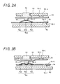
- FIGS. 3A and 3B are figures explaining the operation of the switching device shown in FIG. 1, in which FIG. 3A is a schematic sectional diagram before pushing a button; and FIG. 3B is a schematic sectional diagram after pushing the button.
- a plurality of push-buttons 50 are disposed as an operational button portion in a mobile phone unit; a plurality of switching devices are arranged in a casing including an upper case 51 and a lower case 52; and the upper surfaces 50-1 (refer to FIG. 2B) of the push-buttons 50 functioning as an operational portion for operating the switching devices are exposed from the upper case 51.
- the upper case 51 is formed by molding plastic or the like and is provided with approximately rectangular holes 51a through which the upper surfaces 50-1 of the plurality of push-buttons 50 can be exposed.
- the button 50 is, for example, made of plastic resin whose upper part is transparent, and has the shape of approximately a rectangular parallelepiped, the upper surface 50-1 of which is similar to and smaller than the hole 51a in the upper case 51 as shown in FIG. 2B; and stepped differences are integrally provided on two opposing side surfaces on the side of a bottom surface 50-2 of this approximately rectangular parallelepiped such that the button 50 may not fall off the hole 51a.
- a plurality of the buttons 50 are arranged on a resilient sheet 53 that is an insulating rubber component.
- characters such as the kana and alphabet and numerals are displayed on the surfaces of these buttons 50 by means of printing, stamping, and the like.
- This resilient sheet 53 is made by molding insulating, resilient silicon rubber or the like and is a pliable thin sheet, the back surface 53-2 of which is provided with pushers 53-3, ⁇ , and as shown in FIG. 2B, the buttons 50 are arranged on the front surface 53-1 of the resilient sheet 53, being fixed with adhesive 53a.
- buttons 50 which approximately correspond to the centers of the bottom surfaces 50-2 of the buttons 50 are provided on the back surface 53-2 of the resilient sheet 53. Further, on the resilient sheet 53, the buttons 50 are arranged and fixed with an intended space, so that when fitted into the upper case 51 shown in FIG. 2A, the upper parts of the buttons 50 and the sidewalls of the holes 51a will not interfere with each other.
- a wiring substrate 54 fixed to the side of the lower case 52, as shown in FIG. 2C.
- This wiring substrate 54 is made of a thin printed-wiring board, flexible wiring board and the like, and on the upper surface 54-1 are provided contacts 54a in such positions as correspond to the pushers 53-3 on the back surface 53-2 of the resilient sheet 53.
- the contacts 54a are, for example, ones in which a plurality of dome components 55 formed of metal thin plates are provided on the wiring substrate 54; annular conductive pads 54c are formed on the upper surface 54-1 of the wiring substrate 54 and circular pads 54d formed in the centers of the conductive pads 54c, and the circular peripheries of the dome components 55 are disposed to virtually touch the whole circumference of the annular conductive pads 54c. Further, virtually the whole of the upper surface 54-1 of the substrate 54 is covered with an insulating film not shown in the figure so as to fix the dome components 55.
- buttons 50, the resilient sheet 53 and the wiring substrate 54 having the dome components 55, installed between the upper case 51 and the lower case 52, are assembled without vertical rattling.
- the resilient sheet 53, the wiring substrate 54, the upper case 51 and the lower case 52 are provided with a projection 53-4, a hole 54-2, a depression 51-2 and a protrusion 52-1 respectively, and the projection 53-4 and the hole 54-2 are made to engage with the depression 51-2 and the protrusion 52-1 respectively as shown, for example, in FIG. 3A.
- the state shown in FIG. 3A in which the push-button 50 has not been pushed down changes into the state shown in FIG. 3B by pushing down the button 50
- the resilient sheet 53 changes the shape thereof and bends in a downward direction when pushed by the push-button 50
- the pusher 53-3 pushes down the top of the dome component 55 to be deformed.
- the annular conductive pad 54c and the circular pad 54d are electrically connected to close the contact, and a sensation of clicking at the time of deforming the dome component 55 is felt by a finger used for the operation.
- Patent Literature 1 As this kind of a switching device in a mobile phone unit, an example is disclosed in Patent Literature 1.
- Patent Literature 1 Published Japanese Patent Application No. 6-309992 (page. 2, FIG. 4)
- switching devices of this kind are switches which independently function as simple push-buttons in the past, and switches capable of executing a more advanced input operation using a simple structure have been in great demand.
- the present invention addresses the above-identified, and other problems associated with conventional methods and apparatuses and provides a switch of this kind in which an advanced input operation can be executed using a simple structure.
- a switching device or a mobile phone unit having the switching device includes a button which operates a switch component in accordance with pushing operation, a case which stores the button in a state in which the pushed-down surface of the button is at least exposed, a first position-deciding portion provided on the periphery of the button, and a second position-deciding portion provided on the surface of the case in contact with the button and on the position corresponding to the first position-deciding portion; in which the position of the button is fixed to the case by the first and second position-deciding portions engaging with each other.
- the above-mentioned switching device further includes a substrate on which switch components are arranged, a resilient sheet arranged on this substrate, and a button arranged on this resilient sheet; in which on the periphery of the button are provided a plurality of projections or tapered depressions in the direction approximately at right angles to the pushed-down surface thereof, and on the surface of the case in contact with the button are provided a plurality of tapered depressions or projections which engage with the projections or tapered depressions of the button respectively.
- the position of the button is fixed by the projections or tapered depressions on the case side engaging with the projections or tapered depressions on the button side respectively, thereby making it unnecessary for the button to be stuck to the resilient sheet. Further even if there is a rattle caused by a space between the tapered depressions and projections which are arranged on the case and on the button and which engage with each other after the button has been pushed, it is possible for the button to return to the original position thereof, where the button is centered without the rattle against the hole of the case from which the pushed-down surface of the button is exposed, because when force with which to push down the button is released, the projections on one side follow the tapers of the depressions on the other by means of restoring force generated by the resilience of the resilient sheet and the like; therefore, the button is allowed to be pushed and handled in an inclined state.
- the first position-deciding portion provided on the button engages with the second position-deciding portion provided on the case, a position-adjusting function which makes the button to be in a predetermined position with respect to the case can be given.
- a multifunctional switching device in which four switch components can be operated by one button can be constructed by providing a disk-shaped button, providing four columnar projections whose ends are approximately spherical and/or four tapered depressions with a pitch of approximately 90° with respect to the center of the button while providing four projections and/or four depressions in the vicinity of the hole of the case, and arranging by a pitch of approximately 90° the four switch components each shifted approximately 45° away from the projections or depressions with respect to the center of the button.
- a position-adjusting function is provided, a button is stored in a case without rattling by means of a resilient sheet, and when the force with which the button is pushed down is released, the button can return to the original position thereof, where the button does not rattle against the case by means of the resilient sheet, so that it is not necessary for the button to be fixed in a predetermined position on the resilient sheet, and it is therefore not necessary for the button and the resilient sheet to be stuck together, which can lower the production cost.
- a multifunctional switching device in which four switch components can be operated by one button and when the operational force with which to push down the button is released, the button automatically returns to the original state before pushed down
- a disk-shaped button providing four columnar projections whose ends are approximately spherical and/or four tapered depressions with a pitch of approximately 90° with respect to the center of the button while providing four projections and/or four depressions in the vicinity of the hole of the case, and arranging by a pitch of approximately 90° the four switch components each shifted approximately 45° away from the projections or depressions with respect to the center of the button.
- FIGS. 4 to 17 An embodiment of the present invention will be explained referring to FIGS. 4 to 17.
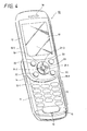
- FIG. 4 is a perspective view showing an example of the outside appearance of a mobile phone unit in which a switching device of this embodiment is provided on the lower side of a display screen.
- FIG. 5 is a perspective view in which the relevant part of the switching device of this embodiment is enlarged and partly shown in section.
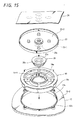
- FIG. 6 is an exploded perspective view for explaining the structure of the switching device of this embodiment.
- FIG. 7 is a sectional view corresponding to the I-I line in FIG. 5.
- FIG. 8 is a perspective view of a direction-inputting button of a switching device of this embodiment shown from the back surface.
- FIG. 9 is a perspective view of a center button assembled into the switching device of this embodiment shown from above, and
- FIG. 10 is a perspective view of the center button inverted and shown from the bottom surface thereof.
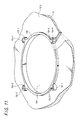
- FIG. 11 is a perspective view showing a hole portion in the back surface of a case, through which a direction-inputting button of the switching device of this embodiment is installed.
- FIG. 12 is a perspective view of a resilient sheet of a switching device of this embodiment.
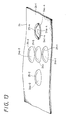
- FIG. 13 is a perspective view showing a wiring substrate which has contacts of the switching device of this embodiment.
- FIG. 14 is a schematic sectional view for explaining the structure of a contact of the switching device of this embodiment.
- FIG. 15 is an exploded perspective view for explaining the assembly order of the switching device of this embodiment.
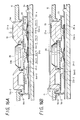
- FIGS. 16A and 16B are provided to explain the operation of the switching device of this embodiment, in which FIG. 16A is a schematic sectional view showing a state before pushing down and FIG. 16B is a schematic sectional view showing a state after pushing down.
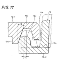
- FIG. 17 is an explanatory diagram showing an engaged state of the switching device when pushed down.
- a reference numeral 10 shows the whole of a mobile phone unit.
- the mobile phone unit 10 includes a dial button portion case 11 and a display portion case 12; and the dial button portion case 11 has a dial button 13 formed of a plurality of buttons for inputting telephone numbers, characters, symbols, and the like, a microphone 14, an antenna portion 15, an incoming lamp 16, and further, a battery, a memory card, and the like not shown in the figure.
- the display portion case 12 is provided with a display 17 made of a liquid-crystal display panel and the like, a receiver 18, a direction-inputting button 19 for moving a cursor and the like shown on the display 17, a center button 26 to determine an item selected by a cursor, four specific input keys 20 and so forth, and these are stored in an external casing formed of a front panel 12-1 and a back panel 12-3.
- FIG. 5 diagonally shows in an enlarged manner the direction-inputting button 19 arranged below the display 17 of the display portion case (hereinafter simply called "case") 12 shown in FIG. 4 and the surrounding area.
- the direction-inputting button 19 is formed into an annular shape, because the button-shaped center button 26 is placed at the center thereof, and the upper surface 19-1 is made to be exposed from a circular hole 12a provided in the front panel 12-1 (refer to FIG. 4) of the case 12.
- the direction-inputting button 19 and the center button 26 are installed in a resilient sheet 23 provided on a wiring substrate 24 to cover an area where five contacts 24a exist, and are fitted into the case 12 in this state.
- the area where the five contacts 24a on the wiring substrate 24 exist is constructed as switch components, each of which is turned on by being pressed from above.
- a pusher 23a-4 of the resilient sheet 23 is positioned immediately under a direction mark 21-4 of the direction-inputting button 19, as shown on the right-hand side in FIG. 7.
- the direction-inputting button 19 shown in FIG. 6 is formed by molding plastic; and as shown in FIG. 5, is a disk having a circular hole 19a in the center thereof, and the circular hole 19a is chamfered a great deal on the upper surface 19-1 side.
- FIG. 8 that is a view shown from the bottom surface 19-2 side, a narrow flange portion 19b is provided on the bottom surface 19-2 side of the side surface 19-3 of the disk, four protuberances are provided on the outside of this flange 19b with a pitch of approximately 90° with respect to the center of the circular hole 19a, and four columnar projections 19c-1 to 19c-4 whose ends are approximately spherical are provided on the upper surfaces of these protuberances.
- FIG. 8 that shows FIG. 5 in an inverted manner
- hole-making processing of counterboring is performed on the circular hole 19a in the center of the direction-inputting button 19 from the bottom surface 19-2 side concentrically with and larger than the circular hole 19a, and a level difference portion 19-4 is provided on the upper surface 19-1 side of the circular hole 19a.
- ribs 19d-1 to 19d-4 which function as switch operators being left. As shown in FIG. 8, these ribs 19d-1 to 19d-4 are provided, being shifted by approximately 45° away from the directions of the four columnar projections 19c-1 to 19c-4 provided on the flange portion 19b of the disk, with respect to the center of the circular hole 19a.
- rod-like direction marks 21-1 to 21-4 which explicitly show the rough positions where the direction-inputting button 19 is pushed down are buried in the upper surface 19-1 of the direction-inputting button 19, corresponding to the positions of the four ribs 19d-1 to 19d-4.
- the center button 26 shown in FIG. 6 is a button-like part molded from plastic and is a disk in the shape of a rough trapezoid in section with respect to the central axis shown in FIG. 9, and a flange portion 26a is provided on the lower part of the side surface 26-3 on the bottom surface 26-2 (refer to FIG. 10) side.
- a groove 26b whose section is approximately rectangular is provided on the bottom surface 26-2 side shown in FIG. 10, and is formed into an annular shape.
- the diameter of the side surface 26-3 of the center button 26 is made smaller than that of the inner circumferential surface 19-6 of the direction-inputting button 19 shown in FIG. 8, and the diameter of the side surface 26-4 of the flange portion 26a of the center button 26 is made smaller than that of the inner circumferential surface 19-7 of the direction-inputting button 19 shown in FIG. 8.
- the front panel 12-1 of the case 12 shown in FIG. 6 which exposes the direction-inputting button 19 is provided with the circular hole 12a which is larger than the outer circumferential surface 19-3 (refer to FIG. 8) of the direction-inputting button 19 and smaller than the outside diameter of the flange 19b.
- a circular wall portion 12b which has a predetermined width and height is provided all around the periphery of the hole 12a, and four tapered depressions 12c-1 to 12c-4 are provided in the vicinity of this wall portion 12b.
- these tapered depressions 12c-1 to 12c-4 are integrally formed in the back surface 12-2 of the front panel 12-1, on the outside the wall portion 12b with a pitch of approximately 90° with respect to the center of the hole 12a, that is, after arranged approximately in contact with the periphery of the wall portion 12b, four columns are joined to the wall portion 12b with smooth surfaces, and the tapered depressions 12c-1 to 12c-4 are formed by performing hole-making processing from above on these four columns in a conical form having an inclination (taper) angle on the inner circumferential surface.
- the tapered depressions 12c-1 to 12c-4 are positioned such that the distance between the central axis of the hole 12a in the front panel 12-1 of the case 12 and the central axes of the holes of the four depressions 12c-1 to 12c-4 and the distance between the central axis of the direction-inputting button 19 and the central axes of the four hemispherical projections 19c-1 to 19c-4 are approximately the same.
- the sides of the tapered depressions 12c-1 to 12c-4, that are close to the columnar hole 12a are trimmed to have approximately the same height as the upper surface 12-4 of the wall portion 12b, and walls 12d-1 to 12d-4 are left on the sides that are a long distance away from the hole 12a of the column.
- the surface on the wall portion 12b of the back surface 12-2 of the front panel 12-1 and the surface 19-5 of the flange portion 19b of the above-mentioned direction-inputting button 19 can be disposed close to each other, and the projections 19c-1 to 19c-4 of the direction-inputting button 19 are controlled by the walls 12d-1 to 12d-4 on the upper part of the tapered depressions 12c-1 to 12c-4 not to come off to a great extent.
- the resilient sheet 23 shown in FIG. 6 is an insulating resilient thin sheet which is approximately circular, into which silicon rubber or the like is molded, the periphery thereof is folded back toward the back surface 23-2 side to be shaped like a skirt, pushers 23a-1 to 23a-4 and 23b are provided, and a cylinder 23c is integrally provided on the front surface 23-1 side.
- the pusher 23b is provided at the approximate center of the resilient sheet 23 through a circular pedestal, and the four pushers 23a-1 to 23a-4 provided around this pusher 23b are arranged at the positions corresponding to the approximate centers of the four ribs 19d-1 to 19d-4 of the direction-inputting button 19 shown in FIG. 8 so as to be pressed, with a pitch of approximately 90° with respect to the center of the pusher 23b (refer to the section shown on the right side of the central axis in FIG. 7).
- the center thereof is made approximately the same as the center of the pusher 23b, and the inside and outside diameters and length thereof are determined such that the cylinder 23c be installed in the rectangular groove 26b in section of the center button 26 shown in FIG. 10 without rattling.
- the height of the five pushers 23a-1 to 23a-4 and 23b above the back surface 23-2 is determined not to cause a vertical rattle (allowance) and not to operate the contact on the wiring substrate 24 when the resilient sheet 23 is fitted into the front panel 12-1 of the case 12 along with the wiring substrate 24 described later on, the direction-inputting button 19 and the center button 26, to be the state shown in FIG. 7.
- the wiring substrate 24 shown in FIG. 6 is a multilayer wiring substrate or another printed circuit substrate that is pliable (flexible) such as a flexible wiring substrate as in FIG. 13 in which the part corresponding to the direction-inputting button 19 is shown; five contacts 24a-1 to 24a-4 and 24b are provided on the upper surface 24-1 of the wiring substrate 24 in the area where the direction-inputting button 19 is provided, and the positions thereof are made to correspond to the pushers 23a-1 to 23a-4 and 23b on the back surface 23-2 of the resilient sheet 23.
- each of the contacts 24a-1 to 24a-4 and 24b is one in which a dome component 25 formed of a metal thin plate is provided on the wiring substrate 24; an annular conductive pad 24c is formed on the upper surface 24-1 of the wiring substrate 24 with a circular pad 24d formed in the center of the conductive pad 24c, and the circular periphery of the dome component 25 is arranged to be virtually in contact with the annular conductive pad 24c on the whole periphery. Further virtually the whole of the upper surface 24-1 of the substrate 24 is covered with an insulating film not shown in the figure so as to fix the dome component 25.
- the switch thus constructed is installed with first the back surface 12-2 side of the front panel 12-1 of the case 12 placed facing upward; then the four approximately spherical projections 19c-1 to 19c-4 are installed in the tapered depressions 12c-1 to 12c-4 provided in the vicinity of the hole 12a in the front panel 12-1, and the direction-inputting button 19 is installed.
- FIGS. 16A and 16B show the I-I section in FIG. 5.
- the state shown in FIG. 16B in which the pushing-down operation is taking place returns to the state shown in FIG. 16A because of the restoring force of the dome components 25-1 to 25-4 and the resilient sheet 23.
- the approximately spherical end of the projection 19c provided in the direction-inputting button 19 is in contact with and follows the taper surface, whose inclination angle is E, of the depression 12c in the back surface 12-2 of the front panel 12-1 of the case 12, and the direction-inputting button 19 is centered in its original position shown by FIG. 16A or shown by the chain double-dashed line in FIG. 17 that is a predetermined state before the pushing-down operation.
- the inclination angle E of the inner walls of the depressions 12c-1 to 12c-4 is made 10 to 20° with respect to the central axes of the holes of the depressions 12c-1 to 12c-4, for example.
- This kind of operation can also be performed by pushing down other direction marks 21-1 to 21-3 of the direction-inputting button 19 shown in FIGS. 4 and 5; the contact 24a-1 can be operated by leaning the direction-inputting button 19 in a downward direction in FIG. 4 (pushing down the direction mark 21-1); the contact 24a-3 can be operated by leaning it in an upward direction in FIG. 4 (pushing down the direction mark 21-3); and the contact 24a-2 can be operated by leaning it in a leftward direction in FIG. 4 (pushing down the direction mark 21-2).
- the direction-inputting button 19 descends by ⁇ in height as a whole and inclines its upper surface 19-1 toward the pushed-down side by an angle ⁇ as described above; as a result, not only the pusher 23a-4 placed immediately below the rib 19-4 but also the pusher 23a-1, 23a-3 or 23a-2 descends. However, the amount by which these pushers 23a-1 to 23a-3 descend is not sufficient to deform the corresponding dome components 25-1 to 25-3 in shape and to close the contacts, so that the contacts 24a-1 to 24a-3 are not operated.
- the switching device of this embodiment can also be used as a five-contact input switching device formed of four contacts by the direction-inputting button 19 and one contact by the center button 26.
- the switching device of this embodiment when the upper part of one of the direction marks 21-1 to 21-4 on the upper surface 19-1 of the direction-inputting button 19 that is an example of a button is pushed down, one of the pushers 23a-1 to 23a-4 on the back surface 23-2 of the resilient sheet 23 is selectively pushed by means of the four ribs 19d-1 to 19d-4 provided on the back surface 19-2, so that it is possible for one annular direction-inputting button 19 to operate one intended contact out of four contacts on the substrate.
- the direction-inputting button 19 is not fixed to the resilient sheet 23, the position to which the direction-inputting button 19 returns does not shift with respect to the hole 12a in the front panel 12-1, even if the direction-inputting button 19 is repeatedly pushed down and released.
- the projections 19c-1 to 19c-4, whose ends are approximately spherical, of the direction-inputting button 19 move along the tapered surfaces of the inner walls of the tapered depressions 12c-1 to 12c-4 in the front panel 12-1 of the case 12 and the direction-inputting button 19 can returned to its original position where centered, so that the hole 12a of the case 12 and the outer circumferential surface 19-3 of the direction-inputting button 19 can always return to the state in which there is an intended space between them.
- direction-inputting button 19 that is an example of a button is not fixed to the resilient sheet 23 in a predetermined position, since there is always an intended space formed between the hole 12a of the case 12 and the direction-inputting button 19 with the release after the pushing-down operation, a switch with a favorable function can be obtained, when the direction-inputting button 19 and the resilient sheet 23 are installed into the case 12 without being stuck and fitted into each other.
- projections 19c whose ends are virtually spherical are provided on the side of the direction-inputting button 19 functioning as an operational button of the switching device while the tapered depressions 12c are provided in the vicinity of the hole 12a in the back surface 12-2 of the front panel 12-1 of the case 12; however not limited thereto, projections may be provided on the case 12 side while tapered depressions may be provided on the button side, and further, needless to say, projections and depressions may be alternately provided both on the direction-inputting button 19 side and in the vicinity of the hole 12a in the case 12, for example.
- annular four-direction inputting button 19 serves as an operational button of the switching device
- the present invention may be applied to a one-input push-button used for inputting characters such as the kana and alphabet and numerals.
- the resilient sheet 23 provided with the pushers 23a-1 to 23a-4 is placed between the direction-inputting button 19 and the wiring substrate 24 provided with the contacts 24a-1 to 24a-4 has been explained; however, if a direction-inputting button is allowed to slightly rattle in a case, protrusions for pressing contacts may be provided on the contact side of the direction-inputting button to operate the contacts on a wiring substrate by directly pushing them down without using a resilient sheet with pushers, for example. On this occasion, if a flexible member such as a flexible wiring board is used for the wiring substrate and a flat insulating resilient sheet is placed thereunder, it is possible to construct a switching device having no rattle in a simple and convenient manner, without specific molding processing to the resilient sheet.
- the above-mentioned embodiment is an example in which the present invention has been applied to an input button of a mobile phone unit, it can also be applied to other electronic equipment such as portable electronic equipment or to an operational button of a remote control device of electronic equipment, and the like.
Landscapes
- Engineering & Computer Science (AREA)
- General Engineering & Computer Science (AREA)
- Theoretical Computer Science (AREA)
- Human Computer Interaction (AREA)
- Physics & Mathematics (AREA)
- General Physics & Mathematics (AREA)
- Switches With Compound Operations (AREA)
- Push-Button Switches (AREA)
- Switch Cases, Indication, And Locking (AREA)
- Telephone Set Structure (AREA)
Applications Claiming Priority (2)
| Application Number | Priority Date | Filing Date | Title |
|---|---|---|---|
| JP2004181451A JP4417789B2 (ja) | 2004-06-18 | 2004-06-18 | スイッチ装置及び携帯端末装置 |
| JP2004181451 | 2004-06-18 |
Publications (1)
| Publication Number | Publication Date |
|---|---|
| EP1607994A1 true EP1607994A1 (en) | 2005-12-21 |
Family
ID=34937450
Family Applications (1)
| Application Number | Title | Priority Date | Filing Date |
|---|---|---|---|
| EP05012805A Ceased EP1607994A1 (en) | 2004-06-18 | 2005-06-14 | Switching device and portable terminal device |
Country Status (5)
| Country | Link |
|---|---|
| US (1) | US7094979B2 (enExample) |
| EP (1) | EP1607994A1 (enExample) |
| JP (1) | JP4417789B2 (enExample) |
| KR (1) | KR20060049226A (enExample) |
| CN (1) | CN100498998C (enExample) |
Cited By (4)
| Publication number | Priority date | Publication date | Assignee | Title |
|---|---|---|---|---|
| EP1610353A1 (en) | 2004-06-25 | 2005-12-28 | Niles Co., Ltd. | Switch device |
| DE102008001086A1 (de) * | 2007-09-20 | 2009-04-16 | Samsung Electro-Mechanics Co., Ltd., Suwon | Drehbare Eingabevorrichtung |
| CN100561627C (zh) * | 2006-03-10 | 2009-11-18 | 鸿富锦精密工业(深圳)有限公司 | 按键组合及使用其的电子产品 |
| EP2073230A4 (en) * | 2006-10-12 | 2013-09-11 | Nec Corp | FUNCTION KEY STRUCTURE |
Families Citing this family (23)
| Publication number | Priority date | Publication date | Assignee | Title |
|---|---|---|---|---|
| US7453446B2 (en) * | 2004-08-20 | 2008-11-18 | Nokia Corporation | Buttons designed for versatile use |
| PT1708216E (pt) * | 2005-03-31 | 2008-02-12 | Tcl & Alcatel Mobile Phones | Dispositivo portátil de comunicação com chave giratória |
| TWI269577B (en) * | 2005-08-12 | 2006-12-21 | Asustek Comp Inc | Electronic device |
| CN100456405C (zh) * | 2005-08-18 | 2009-01-28 | 华硕电脑股份有限公司 | 电子装置 |
| US7442886B2 (en) * | 2006-03-07 | 2008-10-28 | Alps Electric Co., Ltd. | Multi-directional input unit |
| JP4769603B2 (ja) * | 2006-03-16 | 2011-09-07 | アルプス電気株式会社 | 多方向入力装置 |
| US7253368B1 (en) * | 2006-03-27 | 2007-08-07 | Zippy Technology Corp. | Pin anchoring structure for button switches |
| KR101176943B1 (ko) * | 2006-05-09 | 2012-08-30 | 삼성전자주식회사 | 휴대용 기기의 기능키 조립체 |
| JP4605474B2 (ja) * | 2006-06-06 | 2011-01-05 | サンアロー株式会社 | 多方向入力装置 |
| US7427725B2 (en) * | 2006-08-25 | 2008-09-23 | Darfon Electronics Corp. | Keyboards |
| US20080068339A1 (en) * | 2006-09-18 | 2008-03-20 | Henrik Jensfelt | Electronic device with keypad assembly |
| WO2008147266A1 (en) * | 2007-05-30 | 2008-12-04 | Neonode Ab | Multi-function input device |
| CN101364490B (zh) * | 2007-08-06 | 2013-02-20 | 鸿富锦精密工业(深圳)有限公司 | 双色成型按键及其制造方法 |
| US20090045986A1 (en) * | 2007-08-14 | 2009-02-19 | Sony Ericsson Mobile Communications Ab | Illuminated keyboard and light guide for graphic symbols and method |
| US8129645B2 (en) * | 2007-11-13 | 2012-03-06 | Quadtri Technologies, Llc | Dynamically self-stabilizing elastic keyswitch |
| US20100102996A1 (en) * | 2008-10-23 | 2010-04-29 | Yui-Chen Huang | Dome array device and a key structure with the dome array device |
| US8445795B2 (en) * | 2010-10-12 | 2013-05-21 | Cisco Technology, Inc. | Multi function navigational switch |
| JP6009908B2 (ja) * | 2012-10-31 | 2016-10-19 | 株式会社ヴァレオジャパン | 多方向スイッチ |
| JP6349631B2 (ja) * | 2013-06-21 | 2018-07-04 | 株式会社リコー | スイッチ機構、及び電子機器 |
| TWI496030B (zh) * | 2013-07-10 | 2015-08-11 | Ichia Tech Inc | 薄型按鍵結構 |
| US9552939B2 (en) * | 2014-09-15 | 2017-01-24 | Zippy Technology Corp. | Keyboard equipped with multipoint press positions |
| JP2016066543A (ja) * | 2014-09-25 | 2016-04-28 | ブラザー工業株式会社 | 多方向スイッチ |
| JP6567019B2 (ja) * | 2017-11-14 | 2019-08-28 | ホーチキ株式会社 | 発信機及び発信機の取付方法 |
Citations (7)
| Publication number | Priority date | Publication date | Assignee | Title |
|---|---|---|---|---|
| US3483337A (en) * | 1967-01-06 | 1969-12-09 | Gen Motors Corp | Six-way rotary inclined plane centering switch |
| US4786766A (en) * | 1985-08-26 | 1988-11-22 | Canon Kabushiki Kaisha | Keyboard apparatus |
| US5086313A (en) * | 1988-01-28 | 1992-02-04 | Asahi Kogaku Kogyo Kabushiki Kaisha | Operation switch unit for a camera |
| JPH06309992A (ja) | 1993-04-26 | 1994-11-04 | Hitachi Ltd | キーパッド |
| US5525770A (en) | 1992-07-31 | 1996-06-11 | Sega Enterprises, Ltd. | Control-key mechanism having improved operation feeling |
| JPH11329161A (ja) * | 1998-05-20 | 1999-11-30 | Sega Enterp Ltd | コントロールキー装置 |
| EP1460665A2 (en) * | 2003-03-18 | 2004-09-22 | Matsushita Electric Industrial Co., Ltd. | Electronic equipment and pushbutton used therein |
Family Cites Families (8)
| Publication number | Priority date | Publication date | Assignee | Title |
|---|---|---|---|---|
| US3691324A (en) * | 1971-04-28 | 1972-09-12 | Brin Mfg Co Inc | Multiple circuit switch with pivoted contact only one switch operable at a time |
| US4582967A (en) * | 1984-10-22 | 1986-04-15 | Tec, Inc. | Key switch assembly |
| JP2695682B2 (ja) * | 1990-07-10 | 1998-01-14 | 三菱電機株式会社 | 押ボタン機構 |
| JP3951493B2 (ja) * | 1999-03-15 | 2007-08-01 | 松下電器産業株式会社 | 多方向操作スイッチおよびこれを用いた複合スイッチ |
| US6593909B1 (en) * | 2000-06-29 | 2003-07-15 | Shin Jiuh Corp. | Direction-control switch module for controlling a screen cursor |
| JP2003059368A (ja) * | 2001-08-22 | 2003-02-28 | Mitsumi Electric Co Ltd | キースイッチ |
| US6670563B1 (en) * | 2002-12-03 | 2003-12-30 | Samsung Electronics Co., Ltd. | Rotation key device for a portable terminal |
| US6961052B1 (en) * | 2003-03-17 | 2005-11-01 | Cisco Technology, Inc. | Methods and apparatus for providing multi-directional navigation control |
-
2004
- 2004-06-18 JP JP2004181451A patent/JP4417789B2/ja not_active Expired - Fee Related
-
2005
- 2005-06-08 US US11/147,330 patent/US7094979B2/en not_active Expired - Fee Related
- 2005-06-14 EP EP05012805A patent/EP1607994A1/en not_active Ceased
- 2005-06-16 KR KR1020050051900A patent/KR20060049226A/ko not_active Abandoned
- 2005-06-17 CN CNB2005100781539A patent/CN100498998C/zh not_active Expired - Fee Related
Patent Citations (7)
| Publication number | Priority date | Publication date | Assignee | Title |
|---|---|---|---|---|
| US3483337A (en) * | 1967-01-06 | 1969-12-09 | Gen Motors Corp | Six-way rotary inclined plane centering switch |
| US4786766A (en) * | 1985-08-26 | 1988-11-22 | Canon Kabushiki Kaisha | Keyboard apparatus |
| US5086313A (en) * | 1988-01-28 | 1992-02-04 | Asahi Kogaku Kogyo Kabushiki Kaisha | Operation switch unit for a camera |
| US5525770A (en) | 1992-07-31 | 1996-06-11 | Sega Enterprises, Ltd. | Control-key mechanism having improved operation feeling |
| JPH06309992A (ja) | 1993-04-26 | 1994-11-04 | Hitachi Ltd | キーパッド |
| JPH11329161A (ja) * | 1998-05-20 | 1999-11-30 | Sega Enterp Ltd | コントロールキー装置 |
| EP1460665A2 (en) * | 2003-03-18 | 2004-09-22 | Matsushita Electric Industrial Co., Ltd. | Electronic equipment and pushbutton used therein |
Non-Patent Citations (2)
| Title |
|---|
| PATENT ABSTRACTS OF JAPAN vol. 1995, no. 02 31 March 1995 (1995-03-31) * |
| PATENT ABSTRACTS OF JAPAN vol. 2000, no. 02 29 February 2000 (2000-02-29) * |
Cited By (4)
| Publication number | Priority date | Publication date | Assignee | Title |
|---|---|---|---|---|
| EP1610353A1 (en) | 2004-06-25 | 2005-12-28 | Niles Co., Ltd. | Switch device |
| CN100561627C (zh) * | 2006-03-10 | 2009-11-18 | 鸿富锦精密工业(深圳)有限公司 | 按键组合及使用其的电子产品 |
| EP2073230A4 (en) * | 2006-10-12 | 2013-09-11 | Nec Corp | FUNCTION KEY STRUCTURE |
| DE102008001086A1 (de) * | 2007-09-20 | 2009-04-16 | Samsung Electro-Mechanics Co., Ltd., Suwon | Drehbare Eingabevorrichtung |
Also Published As
| Publication number | Publication date |
|---|---|
| CN1710681A (zh) | 2005-12-21 |
| JP4417789B2 (ja) | 2010-02-17 |
| CN100498998C (zh) | 2009-06-10 |
| KR20060049226A (ko) | 2006-05-18 |
| JP2006004830A (ja) | 2006-01-05 |
| US20050279619A1 (en) | 2005-12-22 |
| US7094979B2 (en) | 2006-08-22 |
Similar Documents
| Publication | Publication Date | Title |
|---|---|---|
| EP1607994A1 (en) | Switching device and portable terminal device | |
| US9880648B2 (en) | Touch pad input device | |
| JP5326569B2 (ja) | 入力装置 | |
| US20080309638A1 (en) | Input device and method of manufacturing module unit for input device | |
| EP2602694A2 (en) | Input device and manufacturing method thereof | |
| US20030083021A1 (en) | Keypad assembly | |
| US20100253633A1 (en) | Fingertip tactile-sense input device | |
| US7230197B2 (en) | Movable contact, moveable contact unit including the same, and switch including the same movable contact | |
| CN100468297C (zh) | 操作输入装置和使用该装置的电子设备 | |
| US9715976B2 (en) | Keyboard device | |
| EP0423924A1 (en) | Long traveling button switch with enhanced user feedback | |
| RU2635872C2 (ru) | Корпус, образованный путем двухкомпонентного литья под давлением, с местами для клавишных колпачков в пользовательском интерфейсе | |
| KR101394880B1 (ko) | 디스플레이를 갖는 포웨이 로커 스위치 | |
| US8445795B2 (en) | Multi function navigational switch | |
| JP2001350581A (ja) | 入力装置 | |
| JP2010080330A (ja) | 多方向入力装置 | |
| JP2010153159A (ja) | 多方向スライド式スイッチ | |
| JP2002229478A (ja) | 制御ボタンを形成する表示デバイスを有する電子装置 | |
| US20110187575A1 (en) | Remote control transmitter | |
| CN101860585B (zh) | 移动电子装置及其按键结构 | |
| JP5473061B2 (ja) | 多方向入力スイッチ装置 | |
| JP2570501B2 (ja) | キーボード | |
| JP2004095323A (ja) | キースイッチ装置及びこれを備えた携帯電話機器並びに電子機器 | |
| JP2014071791A (ja) | タッチパネル及びこれを用いた入力装置 | |
| KR20120138469A (ko) | 정보 입력 장치 |
Legal Events
| Date | Code | Title | Description |
|---|---|---|---|
| PUAI | Public reference made under article 153(3) epc to a published international application that has entered the european phase |
Free format text: ORIGINAL CODE: 0009012 |
|
| AK | Designated contracting states |
Kind code of ref document: A1 Designated state(s): AT BE BG CH CY CZ DE DK EE ES FI FR GB GR HU IE IS IT LI LT LU MC NL PL PT RO SE SI SK TR |
|
| AX | Request for extension of the european patent |
Extension state: AL BA HR LV MK YU |
|
| 17P | Request for examination filed |
Effective date: 20060502 |
|
| AKX | Designation fees paid |
Designated state(s): DE FR GB |
|
| 17Q | First examination report despatched |
Effective date: 20120502 |
|
| RAP1 | Party data changed (applicant data changed or rights of an application transferred) |
Owner name: SONY MOBILE COMMUNICATIONS JAPAN, INC. |
|
| STAA | Information on the status of an ep patent application or granted ep patent |
Free format text: STATUS: THE APPLICATION HAS BEEN REFUSED |
|
| 18R | Application refused |
Effective date: 20131012 |