EP2602694A2 - Input device and manufacturing method thereof - Google Patents
Input device and manufacturing method thereof Download PDFInfo
- Publication number
- EP2602694A2 EP2602694A2 EP12164920.6A EP12164920A EP2602694A2 EP 2602694 A2 EP2602694 A2 EP 2602694A2 EP 12164920 A EP12164920 A EP 12164920A EP 2602694 A2 EP2602694 A2 EP 2602694A2
- Authority
- EP
- European Patent Office
- Prior art keywords
- circuit board
- shell
- input device
- mechanical switches
- mechanical
- Prior art date
- Legal status (The legal status is an assumption and is not a legal conclusion. Google has not performed a legal analysis and makes no representation as to the accuracy of the status listed.)
- Withdrawn
Links
Images


Classifications
-
- G—PHYSICS
- G06—COMPUTING; CALCULATING OR COUNTING
- G06F—ELECTRIC DIGITAL DATA PROCESSING
- G06F3/00—Input arrangements for transferring data to be processed into a form capable of being handled by the computer; Output arrangements for transferring data from processing unit to output unit, e.g. interface arrangements
- G06F3/01—Input arrangements or combined input and output arrangements for interaction between user and computer
- G06F3/02—Input arrangements using manually operated switches, e.g. using keyboards or dials
- G06F3/0202—Constructional details or processes of manufacture of the input device
-
- H—ELECTRICITY
- H01—ELECTRIC ELEMENTS
- H01H—ELECTRIC SWITCHES; RELAYS; SELECTORS; EMERGENCY PROTECTIVE DEVICES
- H01H13/00—Switches having rectilinearly-movable operating part or parts adapted for pushing or pulling in one direction only, e.g. push-button switch
- H01H13/70—Switches having rectilinearly-movable operating part or parts adapted for pushing or pulling in one direction only, e.g. push-button switch having a plurality of operating members associated with different sets of contacts, e.g. keyboard
- H01H13/702—Switches having rectilinearly-movable operating part or parts adapted for pushing or pulling in one direction only, e.g. push-button switch having a plurality of operating members associated with different sets of contacts, e.g. keyboard with contacts carried by or formed from layers in a multilayer structure, e.g. membrane switches
- H01H13/705—Switches having rectilinearly-movable operating part or parts adapted for pushing or pulling in one direction only, e.g. push-button switch having a plurality of operating members associated with different sets of contacts, e.g. keyboard with contacts carried by or formed from layers in a multilayer structure, e.g. membrane switches characterised by construction, mounting or arrangement of operating parts, e.g. push-buttons or keys
-
- H—ELECTRICITY
- H01—ELECTRIC ELEMENTS
- H01H—ELECTRIC SWITCHES; RELAYS; SELECTORS; EMERGENCY PROTECTIVE DEVICES
- H01H2215/00—Tactile feedback
- H01H2215/028—Tactile feedback alterable
-
- H—ELECTRICITY
- H01—ELECTRIC ELEMENTS
- H01H—ELECTRIC SWITCHES; RELAYS; SELECTORS; EMERGENCY PROTECTIVE DEVICES
- H01H2221/00—Actuators
- H01H2221/024—Transmission element
- H01H2221/026—Guiding or lubricating nylon
-
- H—ELECTRICITY
- H01—ELECTRIC ELEMENTS
- H01H—ELECTRIC SWITCHES; RELAYS; SELECTORS; EMERGENCY PROTECTIVE DEVICES
- H01H2221/00—Actuators
- H01H2221/056—Modular conception
-
- H—ELECTRICITY
- H01—ELECTRIC ELEMENTS
- H01H—ELECTRIC SWITCHES; RELAYS; SELECTORS; EMERGENCY PROTECTIVE DEVICES
- H01H2221/00—Actuators
- H01H2221/08—Actuators composed of different parts
-
- Y—GENERAL TAGGING OF NEW TECHNOLOGICAL DEVELOPMENTS; GENERAL TAGGING OF CROSS-SECTIONAL TECHNOLOGIES SPANNING OVER SEVERAL SECTIONS OF THE IPC; TECHNICAL SUBJECTS COVERED BY FORMER USPC CROSS-REFERENCE ART COLLECTIONS [XRACs] AND DIGESTS
- Y10—TECHNICAL SUBJECTS COVERED BY FORMER USPC
- Y10T—TECHNICAL SUBJECTS COVERED BY FORMER US CLASSIFICATION
- Y10T29/00—Metal working
- Y10T29/49—Method of mechanical manufacture
- Y10T29/49002—Electrical device making
- Y10T29/49117—Conductor or circuit manufacturing
- Y10T29/49124—On flat or curved insulated base, e.g., printed circuit, etc.
- Y10T29/4913—Assembling to base an electrical component, e.g., capacitor, etc.
- Y10T29/49139—Assembling to base an electrical component, e.g., capacitor, etc. by inserting component lead or terminal into base aperture
Definitions
- This invention is relative to an input device, in particular, relative to an input device with mechanical switch which can be replaced individually.
- peripheral input devices are the first and the most commonly used peripheral input devices. Although many other input devices such as mice, touch panels, digital pens or even sound-actuated mobiles (SAM) had been developed, they are still essential peripheral input devices currently for the advantages of low cost and capability of being input a large number of characters during a short period of time.
- SAM sound-actuated mobiles
- the keyboard can be commonly divided into the membrane keyboard and the mechanical keyboard according to how the keys are actuated.
- the mechanical keyboard is mainly constructed from a keycap, a mechanical switch and a circuit board, in which every button has its own independent keycap, mechanical switch and conductive sheet corresponding to the circuit board.
- the mechanical switch and the conductive sheet connected to the circuit board will be jointly actuated by the keycap to generate an electrical signal to the computer. Thereby completed a signal input operation.
- the mechanical keyboard has a much longer service life and a better tactile sensation than the membrane keyboard, and the mechanical switch of the former could be replaced individually. Hence, the mechanical keyboard is still the professional user's favorite even though it is much more expensive.
- the mechanical switch of the mechanical keyboard can be divided into five different types of brown stemmed switches, blue stemmed switches, black stemmed switches, white stemmed switches and red stemmed switches according to the way of actuation.
- the depression force and tactile feedback vary with the construction of the mechanical switch. The users can select a specified type of switch as required.
- the mechanical switch of the conventional mechanical keyboard is still fixed.
- the mechanical switch In order to make the mechanical switch electrically be connected to the circuit board, the mechanical switch is welded to the circuit board by soldering during the production process of the mechanical keyboard.
- the mechanical switch and the circuit board are secured and cannot be separated easily. Whenever any mechanical switch is out of order, it cannot be replaced easily by the user, so the service life of the mechanical keyboard will be shortened.
- the present invention provides an input device with the mechanical switch which can be replaced individually and the manufacturing method thereof.
- the present invention can solve the aforesaid problems of the conventional mechanical keyboards that the mechanical switches cannot be changed individually since the mechanical switches are soldered to the circuit board.
- the present invention provides an input device.
- the input device includes a circuit board and a plurality of mechanical switches.
- the circuit board has a first surface, a second surface and a plurality of conductive sheets, wherein the first surface and the second surface are formed opposite to each other.
- a plurality of holes are formed on the circuit board and the conductive sheets are disposed on one side of the first surface in pair around each corresponding hole, and each of the conductive sheets has a coupling section.
- the mechanical switches are detachable provided on the second surface of the circuit board, every mechanical switch includes an plunger and a plurality of pins, each of the plungers has a positioning column and the positioning column is embedded in the hole, one end of the pins connect to the plunger, the other end of the pins is configured to pass through the circuit board and attach to the coupling section of the conductive sheets for the mechanical switches electrically connecting to the circuit board respectively.
- the present invention further provides a manufacturing method of the input device which includes following steps. Firstly, providing a circuit board, a plurality of holes being formed on the circuit board, then providing a plurality of conductive sheets on a first surface of the circuit board, the conductive sheets are deployed on one side of the circuit board around every holes in pair, each of the conductive sheets being bended and formed a coupling section, then providing a plurality of mechanical switches, each of the mechanical switches comprising a plunger and a plurality of pins, each of the plungers further comprising a positioning column, and then installing the mechanical switch on a second surface of the circuit board, embedding the plungers of the mechanical switch in the holes with the positioning columns, leading the pins to pass through the circuit board and be attached to the corresponding coupling sections of the conductive sheets for the mechanical switches to electrically connected to the circuit board.
- the present invention is featured by electrically plugging the mechanical switch on the circuit board in modular approach and leading the pins of the mechanical switch to pass through the circuit board and attach to the corresponding conductive sheets on the circuit board.
- the mechanical switches are electrically connected to the circuit board and detachable without being soldered. Hence, users can easily replace the original mechanical switch on the circuit board with other types of mechanical switch, for example, mechanical switch with different pressure load, to meeting requirement and habit of the users.
- FIGs. 1 and 2 are respectively a dimensional view and an exploded view of an input device 10 of the present invention.
- the input device 10 includes a plurality of keycaps 100, a second shell 200, a plurality of mechanical switches 300, a circuit board 400 and a first shell 500.
- the first shell 500 has a space 501, the circuit board 400 is accommodated within the space 501.
- the structures of the mechanical switches 300 and the other elements together with the connecting relationship between the constituent elements will also be described in the following paragraphs.
- FIG. 3 is a partial view of the input device 10 according to a first embodiment of the present invention. It is noted that the following description will focus on the region as shown in FIG. 3 for emphasizing the technical features of the present invention. It will also make the description of the present invention clear enough and fully disclosed for people with ordinary skill in this art to practice according thereto. Also, please refer to the complete structure of the input device 10 as illustrated in FIG. 1 and FIG. 2 when reading the following paragraphs.
- FIGs. 4 and 5 are different partial views of a circuit board 400 according to the first embodiment of the present invention.
- the circuit board 400 of the input device 10 has a first surface 401 and a second surface 405 formed opposite to each other.
- the circuit board 400 also has a plurality of conductive sheets 402.
- a plurality of holes 403 and a plurality of perforations 406 are formed on the circuit board 400.
- the perforations 406 are deployed in pairs around each of the holes 403, and the conductive sheets 402 are deployed next to each perforation 406 in pairs on the first surface 401.
- each of the conductive sheets 402 has a coupling section 404 which bends toward the first surface 401 along the direction of the second surface 405.
- FIG. 6 is a partial view of the mechanical switch 300 of the input device 10 according to the first embodiment of the present invention.
- each of the mechanical switches 300 of the input device 10 in the first embodiment includes a plunger 301 and a plurality of pins 302.
- Each of the plungers 301 further includes a positioning column 303 and a carrying portion 306.
- the positioning column 303 is embedded in the hole 403, so that one end of the pin 302 connected to the plunger 301, and the other end of the pin 302 passes through the circuit board 400 to be attached against the coupling section 404 of the conductive sheet 402.
- the mechanical switch 300 is detachably provided on the second surface 405 of the circuit board 400 and electrically connected to the circuit board 400.
- the mechanical switches 300 herein are common mechanical switches used in the mechanical keyboard.
- the mechanical switches can be divided into several types according to the pressure load that is defined to be the minimum pressure at which the mechanical switch can be actuated when being pressed.
- the mechanical switch has varying pressure load and tactile feedback depending on the internal structure thereof.
- the mechanical switches can be mainly divided into five different types, i.e. brown stemmed switches, blue stemmed switches, black stemmed switches, white stemmed switches and red stemmed switches.
- the pressure load of one of the mechanical switches 300 could be identical to or different from another mechanical switch 300. That is, in the input device 10, the mechanical switches 300 can be all the same partly the same, or different from one another as the case may be.
- the mechanical switches 300 with larger pressure load may be used, while for the keys of the input device 10 usually pressed with ring fingers or pinkies, the mechanical switches 300 with smaller pressure load (low force switch).
- the mechanical switches 300 of the invention can be replaced easily as the user wishes any time without complex procedures because the mechanical switches 300 are directly mounted on the circuit board 400 in a detachable way.
- FIG. 7 is a partial view of the second shell 200 of the input device 10 according to the first embodiment of the present invention.
- the second shell 200 of the input device 10 is combined with the first shell 500 and depressed against the plungers 301 of the mechanical switch 300.
- the second shell 200 has a plurality of openings 201 corresponding to the mechanical switches 300.
- every plunger 301 of the mechanical switch 300 is assembled through the corresponding opening 201.
- a plurality of keycaps 100 of the input device 10 are detachably provided at the other side of the mechanical switch 300 with respect to the positioning column 303 and pins 302 by covering the corresponding plungers 301 individually.
- FIG. 17 is a flow chart of the manufacturing method of the input device 10 according to the first embodiment of the present invention.
- the method of manufacturing the input device 10 of the present invention will be described in detail below.
- the method of manufacturing the input device 10 according to the first embodiment includes the following steps.
- step S101 keycaps 100, the second shell 200, the plurality of mechanical switches 300, the circuit board 400 and the first shell 500 are provided.
- step S102 a plurality of conductive sheets 402 for the circuit board 400 are provided on the first surface 401 thereof, in which the conductive sheets 402 are deployed in pairs at one side of the circuit board 400 adjacent to each hole 403, and a coupling section 404 is formed in each of the conductive sheets 402 by bending the conductive sheet 402 itself.
- the circuit board 400 with the configuration as illustrated in the above is obtained.
- step S103 as shown in FIGs. 8-10 that illustrate step S103 in the method of manufacturing the input device 10 together with FIGs. 2 and 17 , a plurality of mechanical switches 300 are provided on the second surface 405 of the circuit board 400.
- the plungers 301 of the mechanical switches 300 are embedded in the hole 403 by using the positioning column 303.
- the pins 302 of the mechanical switches 300 pass through the circuit board 400 and contact with the coupling section 402 of the conductive sheet 402, so that the mechanical switches 300 can be electrically connected to the circuit board 400.
- it may be considered the mechanical switches 300 of different pressure loads could be selected as needed.
- the preliminary manufacture of the input device is completed once the mechanical switches 300 have been provided on the circuit board 400 in other embodiments of the present invention. If a plurality of keycaps 100 are further combined with the plungers 301 of the mechanical switches 300 correspondingly, the input device 10 can be used as the keyboard for the laptop or portable electronic device such as a mobile phone. In this embodiment, the keyboard of the desktop computer or server as the input device 10 is taken for illustration but the invention is not limited thereto.
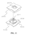
- FIGs. 11-13 illustrate steps S104 and S105 in the method of manufacturing the input device 10 according to the first embodiment of the present invention.
- the circuit board 400 is placed in the space 501 of the first shell 500 (S104), then the second shell 200 is combined with the first shell 500 (S105).
- the second shell 200 is depressed against the carrying portions 306 of the plungers 301 by way of the press-sensitive portion 203.
- the plungers 301 of the mechanical switches 300 will be clasped between the second shell 200 and the circuit board 400 with part thereof assembled through the opening 201 of the second shell 200.
- FIGs. 14-16 illustrate step S106 in the method of manufacturing the input device according to the first embodiment of the present invention.
- a plurality of keycaps 100 are provided at the other side of the plunger 301 with respect to the pins 302, and the keycaps 100 are assembled through the openings 201 of the second shell 200.
- the input device 10 according to the first embodiment is completed.
- sequence of the manufacturing method of the first embodiment is not limited as mentioned. People with ordinary skill can modify the sequence of the manufacturing method in consideration of the production plan or the need without departing from the spirit of the present invention.
- FIG. 18 is a partial view of the input device 10 according to a second embodiment of the present invention.
- the second embodiment is generally similar to the first embodiment except in the former a plurality of bases 600 are added and the structure of the circuit board 400 is changed due to the bases 600.
- FIGs. 19-21 are different partial views of the base 600 according to the second embodiment of the present invention.
- a plurality of bases 600 are provided on the second surface 405 of the circuit board 400.
- Each of the bases 600 includes a depression 601, a plurality of conductive portions 605 and a latching portion 602.
- the latching portion 602 is formed at outer edge of each depression 601.
- a fastening hole 603 and a plurality of insulating holes 604 are formed at the bottom of the depression 601.
- the latching portion 602 has a relatively greater width than the carrying portion 306, the second shell 200 is also depressed against the latching portion 602.
- the latching portion 602 is helpful in increasing the contact area between the mechanical switch 300 and the press-sensitive portion 203, so the mechanical switches 300 could be clasped and stabilized between the second shell 200 and the circuit board 400. As result, the mechanical switches 300 will not separate from the circuit board 400 under the influence of strong shaking or external impact.
- FIGs. 22-23 are partial views of the circuit board 400 according to the second embodiment of the present invention.
- the perforations 406 of the circuit board 400 in the second embodiment has a larger diameter, so that the conductive portions 605 of the bases 600 may be embedded in the perforations 406 and attached against the coupling sections 404 of the conductive sheets 402.
- the pins 302 of the mechanical switches 300 are also electrically plugged in the conductive portions 605 of the bases and indirectly attached to the coupling section 404 of the conductive sheets 402 through the physical contact between the conductive portions 605 and the conductive sheets 402 of the circuit board 400.
- FIG. 35 is a flow chart of the method of manufacturing the input device 10 according to the second embodiment in the present invention that includes the following steps. First, keycaps 100, a second shell 200, a plurality of mechanical switches 300, bases 600, a circuit board 400 and a first shell 500 are provided (S201). Then, a plurality of conductive sheets 402 are provided for the circuit board 400 on the first surface 401 thereof in a similar way to the step of S102 in the first embodiment. The details thereof will not be described repetitively here.
- FIGs. 24-26 illustrate step S203 in the method of manufacturing the input device according to the second embodiment in the present invention.
- the bases 600 are provided on the second surface 405 of the circuit board 400 in a way that the fastening holes 603 of the bases 600 correspond to the holes 403.
- the conductive portions 605 of the bases 600 are embedded in the corresponding perforations 406 of the circuit board 400 and contact the coupling section 404 of the conductive sheets 402.
- FIGs. 27-29 illustrate step S204 in the manufacturing method of the input device according to the second embodiment in the present invention.
- the mechanical switches 300 are provided on the bases 600.
- the mechanical switches 300 are engaged with the corresponding depressions 601 of the bases 600 individually with the plungers 301 in a way that the positioning column 303 is embedded in the fastening hole 603 of the bases 600.
- the pins 302 are configured to pass through the insulating hole 604 and be electrically connected to the coupling section 404 of the conductive sheets 402 on the circuit board 400 by way of the conductive portion 605 of the bases 600.
- FIGs. 30-32 illustrate steps S205 and S206 in the method of manufacturing the input device 10 according to the second embodiment of the present invention.
- the circuit board 400 is provided in the space 501 of the first shell 500.
- the second shell 200 is combined with the first shell 500, the second shell 200 is depressed against the carrying portions 306 of the plungers 301 through the press-sensitive portion 203. In this way, the plunger 301 of the mechanical switch 300 could be clasped and stabilized between the second shell 200 and the circuit board 400 with part thereof assembled through the opening of the second shell 200.
- the second shell 200 when the second shell 200 is combined with the first shell 500, the second shell 200 is depressed against both the latching portion 602 of the base 600 and the carrying portion 306 of the mechanical switch 300.
- the mechanical switch 300 will thus be stablized by the "clasping effect" of the second shell 200 and the circuit board 400.
- FIGs. 33-34 illustrate step S207 in the method of manufacturing the input device 10 according to the second embodiment of the present invention. Then in the step of S207, the keycap 100 is provided at the other side of the mechanical switch 300 with respect to the pins 302 of the plunger 301 and is configured to be assembled through the opening 201 of the second shell 200. Thus the manufacture steps of the input device 10 in the second embodiment are complete.
- the mechanical switch is provided to the circuit board in a modularized way by making the mechanical switch matched with the hole of the circuit board.
- the mechanical switch is electrically connected to the circuit board via the multiple pins passing through the perforations of the circuit board for touching the conductive sheet of the circuit board.
- the mechanical switch is provided stably within the input device with the help of the clasping force formed by the second shell and circuit board.
- the user may desirably choose different types of mechanical switches according to his/her need and habit or may use mechanical switches with different pressure loads for different keys of the input device.
- the mechanical switch can be replaced individually, the user doesn't have to discard the input device if only one or two of the mechanical switches are broken. It is convenient and economic as the service life of the entire input device is extended.
Abstract
Description
- This invention is relative to an input device, in particular, relative to an input device with mechanical switch which can be replaced individually.
- Keyboards are the first and the most commonly used peripheral input devices. Although many other input devices such as mice, touch panels, digital pens or even sound-actuated mobiles (SAM) had been developed, they are still essential peripheral input devices currently for the advantages of low cost and capability of being input a large number of characters during a short period of time.
- The keyboard can be commonly divided into the membrane keyboard and the mechanical keyboard according to how the keys are actuated. The mechanical keyboard is mainly constructed from a keycap, a mechanical switch and a circuit board, in which every button has its own independent keycap, mechanical switch and conductive sheet corresponding to the circuit board. When the keycap is pressed by the user for data input with the keyboard, the mechanical switch and the conductive sheet connected to the circuit board will be jointly actuated by the keycap to generate an electrical signal to the computer. Thereby completed a signal input operation.
- The mechanical keyboard has a much longer service life and a better tactile sensation than the membrane keyboard, and the mechanical switch of the former could be replaced individually. Hence, the mechanical keyboard is still the professional user's favorite even though it is much more expensive. Besides, the mechanical switch of the mechanical keyboard can be divided into five different types of brown stemmed switches, blue stemmed switches, black stemmed switches, white stemmed switches and red stemmed switches according to the way of actuation. The depression force and tactile feedback vary with the construction of the mechanical switch. The users can select a specified type of switch as required.
- However, the mechanical switch of the conventional mechanical keyboard is still fixed. In order to make the mechanical switch electrically be connected to the circuit board, the mechanical switch is welded to the circuit board by soldering during the production process of the mechanical keyboard. Thus, the mechanical switch and the circuit board are secured and cannot be separated easily. Whenever any mechanical switch is out of order, it cannot be replaced easily by the user, so the service life of the mechanical keyboard will be shortened.
- Meanwhile, it is almost impossible to change different types of mechanical switches according to the users' preferences because of the limitation of the conventional technology mentioned above. So, there is a need to improve the conventional mechanical keyboard for the user's convenience.
- Accordingly, the present invention provides an input device with the mechanical switch which can be replaced individually and the manufacturing method thereof. The present invention can solve the aforesaid problems of the conventional mechanical keyboards that the mechanical switches cannot be changed individually since the mechanical switches are soldered to the circuit board.
- The present invention provides an input device. The input device includes a circuit board and a plurality of mechanical switches. The circuit board has a first surface, a second surface and a plurality of conductive sheets, wherein the first surface and the second surface are formed opposite to each other. A plurality of holes are formed on the circuit board and the conductive sheets are disposed on one side of the first surface in pair around each corresponding hole, and each of the conductive sheets has a coupling section. The mechanical switches are detachable provided on the second surface of the circuit board, every mechanical switch includes an plunger and a plurality of pins, each of the plungers has a positioning column and the positioning column is embedded in the hole, one end of the pins connect to the plunger, the other end of the pins is configured to pass through the circuit board and attach to the coupling section of the conductive sheets for the mechanical switches electrically connecting to the circuit board respectively.
- The present invention further provides a manufacturing method of the input device which includes following steps. Firstly, providing a circuit board, a plurality of holes being formed on the circuit board, then providing a plurality of conductive sheets on a first surface of the circuit board, the conductive sheets are deployed on one side of the circuit board around every holes in pair, each of the conductive sheets being bended and formed a coupling section, then providing a plurality of mechanical switches, each of the mechanical switches comprising a plunger and a plurality of pins, each of the plungers further comprising a positioning column, and then installing the mechanical switch on a second surface of the circuit board, embedding the plungers of the mechanical switch in the holes with the positioning columns, leading the pins to pass through the circuit board and be attached to the corresponding coupling sections of the conductive sheets for the mechanical switches to electrically connected to the circuit board.
- The present invention is featured by electrically plugging the mechanical switch on the circuit board in modular approach and leading the pins of the mechanical switch to pass through the circuit board and attach to the corresponding conductive sheets on the circuit board. The mechanical switches are electrically connected to the circuit board and detachable without being soldered. Hence, users can easily replace the original mechanical switch on the circuit board with other types of mechanical switch, for example, mechanical switch with different pressure load, to meeting requirement and habit of the users.
- Further objects, embodiments and advantages are apparent in the drawings and in the detailed description which follows.
- These and other features and advantages of the various embodiments disclosed herein will be better understood with respect to the following description and drawings, in which like numbers refer to like parts throughout, and in which:
-
FIG. 1 illustrates a three-dimensional view of an input device of the present invention; -
FIG. 2 illustrates an exploded view of the input device of the present invention; -
FIG. 3 illustrates a partial view of the input device according to a first embodiment of the present invention; -
FIG. 4 illustrates a partial view of a circuit board according to the first embodiment of the present invention; -
FIG. 5 illustrates another partial view of the circuit board according to the first embodiment of the present invention; -
FIG. 6 illustrates a partial view of a mechanical switch according to the first embodiment of the present invention; -
FIG. 7 illustrates a partial view of a second shell according to the first embodiment of the present invention; -
FIG. 8 ,9 and10 illustrate schematically a step in a manufacturing method of the input device according to the first embodiment of the present invention; -
FIG. 11 ,12 and13 illustrate schematically another step in the manufacturing method of the input device according to the first embodiment of the present invention; -
FIG. 14 ,15 and16 illustrate schematically still another step in the manufacturing method of the input device according to the first embodiment of the present invention; -
FIG. 17 illustrates a flow chart in the manufacturing method of the input device according to the first embodiment of the present invention; -
FIG. 18 illustrates a partial view of the input device according to a second embodiment of the present invention; -
FIG. 19 illustrates a partial view of a base according to the second embodiment of the present invention; -
FIG. 20 illustrates another partial view of the base according to the second embodiment of the present invention; -
FIG. 21 illustrates another partial view of the base according to the second embodiment of the present invention; -
FIG. 22 illustrates a partial view of the circuit board according to the second embodiment of the present invention; -
FIG. 23 illustrates another partial view of the circuit board according to the second embodiment of the present invention; -
FIG. 24 ,25 and26 illustrate schematically a step in a manufacturing method of the input device according to the second embodiment of the present invention; -
FIG. 27 ,28 and29 illustrate schematically another step in the manufacture method of the input device according to the second embodiment of the present invention; -
FIG. 30 ,31 and32 illustrate schematically further step in the manufacture method of the input device according to the second embodiment of the present invention; -
FIG. 33 and34 illustrate schematically further another step in the manufacture method of the input device according to the second embodiment of the present invention; and -
FIG. 35 illustrates a flow chart in the manufacture method of the input device according to the second embodiment in the present invention. -
FIGs. 1 and2 are respectively a dimensional view and an exploded view of aninput device 10 of the present invention. Referring toFIGs. 1 and2 , in the first embodiment, theinput device 10 includes a plurality ofkeycaps 100, asecond shell 200, a plurality ofmechanical switches 300, acircuit board 400 and afirst shell 500. Thefirst shell 500 has aspace 501, thecircuit board 400 is accommodated within thespace 501. In addition, the structures of themechanical switches 300 and the other elements together with the connecting relationship between the constituent elements will also be described in the following paragraphs. -
FIG. 3 is a partial view of theinput device 10 according to a first embodiment of the present invention. It is noted that the following description will focus on the region as shown inFIG. 3 for emphasizing the technical features of the present invention. It will also make the description of the present invention clear enough and fully disclosed for people with ordinary skill in this art to practice according thereto. Also, please refer to the complete structure of theinput device 10 as illustrated inFIG. 1 andFIG. 2 when reading the following paragraphs. -
FIGs. 4 and5 are different partial views of acircuit board 400 according to the first embodiment of the present invention. In the first embodiment, as shown inFIGs. 4 ,5 along withFIGs. 2 and3 , thecircuit board 400 of theinput device 10 has afirst surface 401 and asecond surface 405 formed opposite to each other. Thecircuit board 400 also has a plurality ofconductive sheets 402. A plurality ofholes 403 and a plurality ofperforations 406 are formed on thecircuit board 400. Theperforations 406 are deployed in pairs around each of theholes 403, and theconductive sheets 402 are deployed next to eachperforation 406 in pairs on thefirst surface 401. Besides, each of theconductive sheets 402 has acoupling section 404 which bends toward thefirst surface 401 along the direction of thesecond surface 405. -
FIG. 6 is a partial view of themechanical switch 300 of theinput device 10 according to the first embodiment of the present invention. As shown inFIGs. 2 ,3 and6 , each of themechanical switches 300 of theinput device 10 in the first embodiment includes aplunger 301 and a plurality ofpins 302. Each of theplungers 301 further includes apositioning column 303 and a carryingportion 306. When one of themechanical switch 300 is connected to thecircuit board 400, thepositioning column 303 is embedded in thehole 403, so that one end of thepin 302 connected to theplunger 301, and the other end of thepin 302 passes through thecircuit board 400 to be attached against thecoupling section 404 of theconductive sheet 402. In this way, themechanical switch 300 is detachably provided on thesecond surface 405 of thecircuit board 400 and electrically connected to thecircuit board 400. - It is noted that the
mechanical switches 300 herein are common mechanical switches used in the mechanical keyboard. The mechanical switches can be divided into several types according to the pressure load that is defined to be the minimum pressure at which the mechanical switch can be actuated when being pressed. The mechanical switch has varying pressure load and tactile feedback depending on the internal structure thereof. - As described above, the mechanical switches can be mainly divided into five different types, i.e. brown stemmed switches, blue stemmed switches, black stemmed switches, white stemmed switches and red stemmed switches. In this embodiment, the pressure load of one of the
mechanical switches 300 could be identical to or different from anothermechanical switch 300. That is, in theinput device 10, themechanical switches 300 can be all the same partly the same, or different from one another as the case may be. - For example, for the keys of the
input device 10 usually pressed with thumbs, forefingers, or middle fingers, themechanical switches 300 with larger pressure load (high force switch) may be used, while for the keys of theinput device 10 usually pressed with ring fingers or pinkies, themechanical switches 300 with smaller pressure load (low force switch). Themechanical switches 300 of the invention can be replaced easily as the user wishes any time without complex procedures because themechanical switches 300 are directly mounted on thecircuit board 400 in a detachable way. -
FIG. 7 is a partial view of thesecond shell 200 of theinput device 10 according to the first embodiment of the present invention. As shown inFIGs. 2 ,3 and7 , thesecond shell 200 of theinput device 10 is combined with thefirst shell 500 and depressed against theplungers 301 of themechanical switch 300. Thesecond shell 200 has a plurality ofopenings 201 corresponding to the mechanical switches 300. When one of themechanical switch 300 is connected to thesecond shell 200, everyplunger 301 of themechanical switch 300 is assembled through thecorresponding opening 201. Besides, a plurality ofkeycaps 100 of theinput device 10 are detachably provided at the other side of themechanical switch 300 with respect to thepositioning column 303 and pins 302 by covering the correspondingplungers 301 individually. -
FIG. 17 is a flow chart of the manufacturing method of theinput device 10 according to the first embodiment of the present invention. The method of manufacturing theinput device 10 of the present invention will be described in detail below. Referring toFIGs. 2 and17 , the method of manufacturing theinput device 10 according to the first embodiment includes the following steps. In step S101,keycaps 100, thesecond shell 200, the plurality ofmechanical switches 300, thecircuit board 400 and thefirst shell 500 are provided. Then in step S102, a plurality ofconductive sheets 402 for thecircuit board 400 are provided on thefirst surface 401 thereof, in which theconductive sheets 402 are deployed in pairs at one side of thecircuit board 400 adjacent to eachhole 403, and acoupling section 404 is formed in each of theconductive sheets 402 by bending theconductive sheet 402 itself. Thus, thecircuit board 400 with the configuration as illustrated in the above is obtained. - Next, in step S103, as shown in
FIGs. 8-10 that illustrate step S103 in the method of manufacturing theinput device 10 together withFIGs. 2 and17 , a plurality ofmechanical switches 300 are provided on thesecond surface 405 of thecircuit board 400. Theplungers 301 of themechanical switches 300 are embedded in thehole 403 by using thepositioning column 303. Thepins 302 of themechanical switches 300 pass through thecircuit board 400 and contact with thecoupling section 402 of theconductive sheet 402, so that themechanical switches 300 can be electrically connected to thecircuit board 400. Meanwhile, in the step of providing themechanical switches 300 to thecircuit board 400, it may be considered themechanical switches 300 of different pressure loads could be selected as needed. - It is appreciated that the preliminary manufacture of the input device is completed once the
mechanical switches 300 have been provided on thecircuit board 400 in other embodiments of the present invention. If a plurality ofkeycaps 100 are further combined with theplungers 301 of themechanical switches 300 correspondingly, theinput device 10 can be used as the keyboard for the laptop or portable electronic device such as a mobile phone. In this embodiment, the keyboard of the desktop computer or server as theinput device 10 is taken for illustration but the invention is not limited thereto. -
FIGs. 11-13 illustrate steps S104 and S105 in the method of manufacturing theinput device 10 according to the first embodiment of the present invention. As shown in the figures, after connecting thecircuit board 400 and themechanical switch 300, thecircuit board 400 is placed in thespace 501 of the first shell 500 (S104), then thesecond shell 200 is combined with the first shell 500 (S105). Thesecond shell 200 is depressed against the carryingportions 306 of theplungers 301 by way of the press-sensitive portion 203. Hence, theplungers 301 of themechanical switches 300 will be clasped between thesecond shell 200 and thecircuit board 400 with part thereof assembled through theopening 201 of thesecond shell 200. -
FIGs. 14-16 illustrate step S106 in the method of manufacturing the input device according to the first embodiment of the present invention. As shown in the figures, in the step of S106, a plurality ofkeycaps 100 are provided at the other side of theplunger 301 with respect to thepins 302, and thekeycaps 100 are assembled through theopenings 201 of thesecond shell 200. Thus, theinput device 10 according to the first embodiment is completed. - It is noted that the sequence of the manufacturing method of the first embodiment is not limited as mentioned. People with ordinary skill can modify the sequence of the manufacturing method in consideration of the production plan or the need without departing from the spirit of the present invention.
-
FIG. 18 is a partial view of theinput device 10 according to a second embodiment of the present invention. The second embodiment is generally similar to the first embodiment except in the former a plurality ofbases 600 are added and the structure of thecircuit board 400 is changed due to thebases 600. -
FIGs. 19-21 are different partial views of the base 600 according to the second embodiment of the present invention. In theinput device 10 according to the second embodiment of the present invention, as shown inFIGs. 18-21 , a plurality ofbases 600 are provided on thesecond surface 405 of thecircuit board 400. Each of thebases 600 includes adepression 601, a plurality ofconductive portions 605 and a latchingportion 602. The latchingportion 602 is formed at outer edge of eachdepression 601. Afastening hole 603 and a plurality of insulatingholes 604 are formed at the bottom of thedepression 601. When themechanical switch 300 are detachably provided to thebase 600, theplunger 301 of themechanical switch 300 is engaged with thedepression 601 via thefastening hole 603. thepositioning column 303 of theplunger 301 are embedded in thehole 403 through thefastening hole 603, and thepins 302 of themechanical switch 300 pass through the insulatinghole 604 correspondingly. - When the
second shell 200 is depressed against themechanical switches 300 in the second embodiment as in the first embodiment, since the latchingportion 602 has a relatively greater width than the carryingportion 306, thesecond shell 200 is also depressed against the latchingportion 602. The latchingportion 602 is helpful in increasing the contact area between themechanical switch 300 and the press-sensitive portion 203, so themechanical switches 300 could be clasped and stabilized between thesecond shell 200 and thecircuit board 400. As result, themechanical switches 300 will not separate from thecircuit board 400 under the influence of strong shaking or external impact. - Besides, the
circuit board 400 of theinput device 10 in the second embodiment is different from that in the first embodiment.FIGs. 22-23 are partial views of thecircuit board 400 according to the second embodiment of the present invention. Referring toFIGs. 22 and23 , and alsoFIGs. 4 and5 , theperforations 406 of thecircuit board 400 in the second embodiment has a larger diameter, so that theconductive portions 605 of thebases 600 may be embedded in theperforations 406 and attached against thecoupling sections 404 of theconductive sheets 402. In addition, thepins 302 of themechanical switches 300 are also electrically plugged in theconductive portions 605 of the bases and indirectly attached to thecoupling section 404 of theconductive sheets 402 through the physical contact between theconductive portions 605 and theconductive sheets 402 of thecircuit board 400. -
FIG. 35 is a flow chart of the method of manufacturing theinput device 10 according to the second embodiment in the present invention that includes the following steps. First, keycaps 100, asecond shell 200, a plurality ofmechanical switches 300,bases 600, acircuit board 400 and afirst shell 500 are provided (S201). Then, a plurality ofconductive sheets 402 are provided for thecircuit board 400 on thefirst surface 401 thereof in a similar way to the step of S102 in the first embodiment. The details thereof will not be described repetitively here. -
FIGs. 24-26 illustrate step S203 in the method of manufacturing the input device according to the second embodiment in the present invention. In the step of S203, thebases 600 are provided on thesecond surface 405 of thecircuit board 400 in a way that the fastening holes 603 of thebases 600 correspond to theholes 403. At the same time, theconductive portions 605 of thebases 600 are embedded in the correspondingperforations 406 of thecircuit board 400 and contact thecoupling section 404 of theconductive sheets 402. -
FIGs. 27-29 illustrate step S204 in the manufacturing method of the input device according to the second embodiment in the present invention. Next, in the step of S204, themechanical switches 300 are provided on thebases 600. Themechanical switches 300 are engaged with the correspondingdepressions 601 of thebases 600 individually with theplungers 301 in a way that thepositioning column 303 is embedded in thefastening hole 603 of thebases 600. Thepins 302 are configured to pass through the insulatinghole 604 and be electrically connected to thecoupling section 404 of theconductive sheets 402 on thecircuit board 400 by way of theconductive portion 605 of thebases 600. -
FIGs. 30-32 illustrate steps S205 and S206 in the method of manufacturing theinput device 10 according to the second embodiment of the present invention. In the step of S205, thecircuit board 400 is provided in thespace 501 of thefirst shell 500. In the step of S206, thesecond shell 200 is combined with thefirst shell 500, thesecond shell 200 is depressed against the carryingportions 306 of theplungers 301 through the press-sensitive portion 203. In this way, theplunger 301 of themechanical switch 300 could be clasped and stabilized between thesecond shell 200 and thecircuit board 400 with part thereof assembled through the opening of thesecond shell 200. Therefore, when thesecond shell 200 is combined with thefirst shell 500, thesecond shell 200 is depressed against both the latchingportion 602 of thebase 600 and the carryingportion 306 of themechanical switch 300. Themechanical switch 300 will thus be stablized by the "clasping effect" of thesecond shell 200 and thecircuit board 400. -
FIGs. 33-34 illustrate step S207 in the method of manufacturing theinput device 10 according to the second embodiment of the present invention. Then in the step of S207, thekeycap 100 is provided at the other side of themechanical switch 300 with respect to thepins 302 of theplunger 301 and is configured to be assembled through theopening 201 of thesecond shell 200. Thus the manufacture steps of theinput device 10 in the second embodiment are complete. - In the input device of the invention, the mechanical switch is provided to the circuit board in a modularized way by making the mechanical switch matched with the hole of the circuit board. The mechanical switch is electrically connected to the circuit board via the multiple pins passing through the perforations of the circuit board for touching the conductive sheet of the circuit board. As a result, it will greatly increase user's convenience on replacing the mechanical switch because welding or soldering is not necessary. Besides, the mechanical switch is provided stably within the input device with the help of the clasping force formed by the second shell and circuit board.
- Furthermore, because of the direct and convenient replacement of the mechanical switch, the user may desirably choose different types of mechanical switches according to his/her need and habit or may use mechanical switches with different pressure loads for different keys of the input device.
- Moreover, since the mechanical switch can be replaced individually, the user doesn't have to discard the input device if only one or two of the mechanical switches are broken. It is convenient and economic as the service life of the entire input device is extended.
- While the disclosure has been described in terms of what is presently consider to be the preferred embodiments, it is to be understood that the disclosure needs not be limited to the disclosed embodiment. On the contrary, it is intended cover various modifications and similar arrangements included within the spirit and scope of the appended claims which are to be accorded with the broadest interpretation so as to encompass all such modification and similar structures. It is therefore intended by the appended claims to define the true scope of the invention.
Claims (15)
- An input device (10), characterized by comprising:a circuit board (400) comprising a first surface (401), a second surface (405) formed opposite to the first surface (401), and a plurality of conductive sheets (402), a plurality of holes (403) and perforations (406) being formed on the circuit board (400) and the perforations (406) being deployed around each of the holes (403) in pairs, the conductive sheets (402) being provided adjacent to the holes (403) in pairs on the first surface (401) and each of the conductive sheets (402) comprising a coupling section (404), the coupling section (404) being bent toward the first surface (401) along a direction of the second surface (405); anda plurality of mechanical switches (300) detachably provided on the second surface (405) of the circuit board (400), each of the mechanical switches (300) comprising a plunger (301) and a plurality of pins (302), the plunger (301) further comprising a positioning column (303) embedded in the hole (403), the pin (302) being connected to the plunger (301) at one end and passing through the circuit board (400) at the other end to contact with the coupling section (404) of the conductive sheet (402), and the mechanical switches (300) are electrically connected to the circuit board (400) respectively.
- The input device (10) according to claim 1, characterized by further comprising:a first shell (500) forming a space (501), the circuit board (400) being accommodated within the space (501); anda second shell (200) combined with the first shell (500) and depressed against the plungers (301) of the mechanical switches (300), the second shell (200) further comprising a plurality of openings (201), the openings (201) being corresponding to the mechanical switches (300), and the plunger (301) of each mechanical switch (300) assembled through the opening (201).
- The input device (10) according to claim 2, characterized in that the second shell (200) comprises a plurality of press-sensitive portions (203), each of the plungers (301) comprises a carrying portion (306), and the second shell (200) is depressed the carrying portion (306) of each mechanical switch (300) through the corresponding press-sensitive portion (203).
- The input device (10) according to claim 2, characterized by further comprising a plurality of bases (600) disposed on the second surface (405) of the circuit board (400), wherein each of the bases (600) comprises a depression (601) and a latching portion (602), the latching portion (602) of each base (600) is disposed on an outer edge of the depression (601), a fastening hole (603) and a plurality of insulating holes (604) are formed on the bottom of the depression (601), the plunger (301) of the mechanical switch (300) is engaged with the depression (601), the positioning column (303) is embedded in the hole (403) through the fastening hole (603), the pins (302) pass through the insulating holes (604) correspondingly, and the second shell (200) is depressed on the latching portion (602).
- The input device (10) according to claim 4, characterized in that each of the bases (600) further comprises a plurality of conductive portions (605), the conductive portions (605) are embedded correspondingly in the perforations (406) and attached to the coupling sections (404) of the conductive sheets (402), the pins (302) of the mechanical switch (300) are electrically plugged in the conductive portions (605) through the insulating holes (604) so as to be attached to the coupling sections (404) of the conductive sheet (402) by way of the conductive portions (605).
- The input device (10) according to claim 4, characterized in that the width of the latching portions (602) is greater than the width of the carrying portions (306).
- The input device (10) according to claim 1, characterized by further comprising a plurality of keycaps (100), each of the keycaps (100) is detachably provided at the other side of the corresponding plunger (301) with respect to the positioning column (303) and pins (302).
- The input device (10) according to claim 1, characterized in that the mechanical switches (300) have optionally identical or different pressure loads from one another.
- A manufacturing method of an input device(10), characterized by comprising steps of:providing a circuit board (400) on which a plurality of holes (403) are formed;providing a plurality of conductive sheets (402) on a first surface (401) of the circuit board (400), the conductive sheets (402) being deployed at one side of the circuit board (400) around each hole (403) in pairs, each of the conductive sheets (402) being bent to form a coupling section (404);providing a plurality of mechanical switches (300), each of which comprises a plunger (301) and a plurality of pins (302), and the plunger (301) comprises a positioning column (303); andproviding the mechanical switches (300) on a second surface (405) of the circuit board (400), embedding the plungers (301) of the mechanical switches (300) in the holes (403) by way of the positioning columns (303), making the pins (302) pass through the circuit board (400) and attached against the corresponding coupling sections (404) of the conductive sheets (402) for the mechanical switch (303) electrically to be connected to the circuit board (400).
- The manufacturing method of the input device (10) according to claim 9, characterized by further comprising steps of:providing a first shell (500) and a second shell (200);providing the circuit board (400) in a space (501) of the first shell (500); andcombining the second shell (200) with the first shell (500) and depressing the second shell (200) against the plungers (301) of the mechanical switches (300) and making the plunger (301) of each mechanical switch (300) to fastened between the second shell (200) and the circuit board (400) and assembled through an corresponding opening (201) on the second shell (200).
- The manufacturing method of the input device (10) according to claim 10, characterized by further comprising steps of:providing a plurality of bases (600), each of which comprises a depression (601) and a latching portion (602), and a fastening hole (603) and a plurality of insulating holes (604) are formed on the bottom of the depression (605);disposing the bases (600) on the second surface (405) of the circuit board (400) so that the fastening holes (603) of the bases (600) correspond to the holes (403), and the second shell (200) is depressed against the latching portion (602) of the bases (600) when combining the second shell (200) with the first shell (500); andproviding the mechanical switches (300) on the bases (600), the plungers (301) of the mechanical switches (300) being engaged with the corresponding depression (601) on the bases (600) individually, the positioning column (303) being embedded in the fastening hole (603) of the base (600) and the pins (302) passing through the corresponding insulating holes (604).
- The manufacturing method of the input device (10) according to claim 11, characterized in that the bases (600) are connected to the circuit board (400) by embedding a plurality of conductive portions (605) of the bases (600) in a plurality of perforations (406) of the circuit board (400) so as to be attached to the coupling sections (404) of the conductive sheets (402), wherein the pins (302) of the mechanical switches (300) are electrically plugged in the conductive portions (605) through the insulating holes (604).
- The manufacturing method of the input device (10) according to claim 10, characterized in that the second shell (200) is depressed against a carrying portion (306) of the plunger (301) by way of a press-sensitive portion (203) thereof.
- The manufacturing method of the input device (10) according to claim 9, characterized by further comprising steps of :providing a plurality of keycaps (100) at the other side of the corresponding plungers (301) respectively with respect to the positioning column (303) and pins (302) and making the keycaps (100) exposed form the corresponding openings (201) of the second shell (200).
- The manufacturing method of the input device (10) according to claim 9, characterized in that in the step of providing the mechanical switches (300) on the second surface (405) of the circuit board (400), the mechanical switches (300) having identical or different pressure loads from one another are used optionally.
Applications Claiming Priority (1)
| Application Number | Priority Date | Filing Date | Title |
|---|---|---|---|
| TW100144746A TWI456614B (en) | 2011-12-05 | 2011-12-05 | Input device and manufacturing method thereof |
Publications (2)
| Publication Number | Publication Date |
|---|---|
| EP2602694A2 true EP2602694A2 (en) | 2013-06-12 |
| EP2602694A3 EP2602694A3 (en) | 2016-07-20 |
Family
ID=46084807
Family Applications (1)
| Application Number | Title | Priority Date | Filing Date |
|---|---|---|---|
| EP12164920.6A Withdrawn EP2602694A3 (en) | 2011-12-05 | 2012-04-20 | Input device and manufacturing method thereof |
Country Status (5)
| Country | Link |
|---|---|
| US (1) | US8878085B2 (en) |
| EP (1) | EP2602694A3 (en) |
| JP (1) | JP5463387B2 (en) |
| CN (1) | CN103135777B (en) |
| TW (1) | TWI456614B (en) |
Cited By (1)
| Publication number | Priority date | Publication date | Assignee | Title |
|---|---|---|---|---|
| WO2022117886A1 (en) * | 2020-12-04 | 2022-06-09 | 360 Service Agency GmbH | Mechanical keyboard and corresponding methods |
Families Citing this family (19)
| Publication number | Priority date | Publication date | Assignee | Title |
|---|---|---|---|---|
| US9165723B2 (en) | 2012-08-23 | 2015-10-20 | Harris Corporation | Switches for use in microelectromechanical and other systems, and processes for making same |
| US9053873B2 (en) | 2012-09-20 | 2015-06-09 | Harris Corporation | Switches for use in microelectromechanical and other systems, and processes for making same |
| US9053874B2 (en) | 2012-09-20 | 2015-06-09 | Harris Corporation | MEMS switches and other miniaturized devices having encapsulating enclosures, and processes for fabricating same |
| US8907849B2 (en) | 2012-10-12 | 2014-12-09 | Harris Corporation | Wafer-level RF transmission and radiation devices |
| US9203133B2 (en) | 2012-10-18 | 2015-12-01 | Harris Corporation | Directional couplers with variable frequency response |
| US9734965B2 (en) * | 2013-09-23 | 2017-08-15 | Industrias Lorenzo, S.A. | Arrangement of pushbutton switches with a programmable display |
| TWI564922B (en) * | 2015-11-20 | 2017-01-01 | 致伸科技股份有限公司 | Key connecting module |
| US10714280B1 (en) * | 2016-03-17 | 2020-07-14 | Shazim Mohammad | Mechanical keyboard with modular removable switches support |
| US9941070B2 (en) * | 2016-03-25 | 2018-04-10 | Darfon Electronics (Suzhou) Co., Ltd. | Keyswitch structure mounted within a circuit board and baseplate |
| US10755877B1 (en) * | 2016-08-29 | 2020-08-25 | Apple Inc. | Keyboard for an electronic device |
| TWM537298U (en) * | 2016-09-09 | 2017-02-21 | Chicony Electronics Co | Improved structure of switch-type key |
| TWI623953B (en) * | 2016-10-28 | 2018-05-11 | 致伸科技股份有限公司 | Keyboard |
| CN106825923B (en) * | 2017-02-09 | 2018-11-16 | 深圳市吉祥云科技有限公司 | The welding technique of aluminium sheet and aluminum frame component in a kind of 3C keyboard |
| CN109920678B (en) * | 2017-12-12 | 2022-06-28 | 东普雷股份有限公司 | Keyboard switch |
| US10325734B1 (en) * | 2018-01-30 | 2019-06-18 | Topre Corporation | Keyboard switch |
| KR101868005B1 (en) * | 2018-04-09 | 2018-06-20 | 몬스타 주식회사 | Computer keyboard |
| CN113568513A (en) * | 2020-04-28 | 2021-10-29 | 华硕电脑股份有限公司 | Mouse (Saggar) |
| CN112949240B (en) * | 2021-03-22 | 2023-08-01 | 梁文毅 | Multi-physical field coupling simulation method for centralized parameter model |
| WO2023028978A1 (en) * | 2021-09-03 | 2023-03-09 | Microsoft Technology Licensing, Llc | Through hole keyboard |
Family Cites Families (21)
| Publication number | Priority date | Publication date | Assignee | Title |
|---|---|---|---|---|
| JPS60136151U (en) | 1984-02-20 | 1985-09-10 | 関西西本電気株式会社 | semiconductor socket |
| JPH0229734Y2 (en) | 1985-05-13 | 1990-08-09 | ||
| JPS6223028U (en) * | 1985-07-27 | 1987-02-12 | ||
| JPS62187337U (en) | 1986-05-20 | 1987-11-28 | ||
| JPH04250516A (en) * | 1991-01-25 | 1992-09-07 | Pfu Ltd | Keyboard |
| JPH0619601A (en) | 1991-06-28 | 1994-01-28 | Toyo Commun Equip Co Ltd | Key input device and key block |
| JPH0511242U (en) | 1991-07-23 | 1993-02-12 | 日本電気株式会社 | Operation switch |
| JPH09162061A (en) | 1995-12-12 | 1997-06-20 | Hitachi Ltd | Method and device for connecting capacitor |
| JP3583923B2 (en) * | 1998-05-22 | 2004-11-04 | ホシデン株式会社 | Keyboard switch |
| JP2001068182A (en) * | 1999-08-27 | 2001-03-16 | Sony Computer Entertainment Inc | Board connecting structure, electronic equipment, and connector |
| JP2001195948A (en) * | 2000-01-07 | 2001-07-19 | Brother Ind Ltd | Key switch device, keyboard having key switch device, and electronic equipment having key board |
| JP4533559B2 (en) * | 2001-06-07 | 2010-09-01 | 富士通株式会社 | Key switch and keyboard |
| US6903662B2 (en) * | 2002-09-19 | 2005-06-07 | Ergodex | Computer input device with individually positionable and programmable input members |
| JP4146396B2 (en) | 2004-06-15 | 2008-09-10 | スガツネ工業株式会社 | Telescopic stay |
| TWI256573B (en) * | 2004-11-02 | 2006-06-11 | Zippy Tech Corp | Cover-lifting type faceplate changeable keyboard |
| JP4105706B2 (en) * | 2005-02-22 | 2008-06-25 | 不二電子工業株式会社 | Conduction terminal |
| TWM321127U (en) * | 2007-03-30 | 2007-10-21 | Can Technology Co Ltd | Keystroke structure for keyboard |
| TWM354115U (en) * | 2008-09-26 | 2009-04-01 | Darfon Electronics Corp | Keyboard structure |
| CN102208292A (en) * | 2010-03-30 | 2011-10-05 | 深圳富泰宏精密工业有限公司 | Key structure of portable electronic device |
| WO2011137382A2 (en) * | 2010-04-30 | 2011-11-03 | Ikey, Ltd. | Panel mount keyboard system |
| TWM394522U (en) * | 2010-07-14 | 2010-12-11 | Sunrex Technology Corp | Improved structure of light-emitting keyboard |
-
2011
- 2011-12-05 TW TW100144746A patent/TWI456614B/en active
-
2012
- 2012-02-27 CN CN201210046554.6A patent/CN103135777B/en active Active
- 2012-04-20 EP EP12164920.6A patent/EP2602694A3/en not_active Withdrawn
- 2012-04-30 US US13/460,070 patent/US8878085B2/en active Active
- 2012-06-26 JP JP2012142586A patent/JP5463387B2/en active Active
Non-Patent Citations (1)
| Title |
|---|
| None |
Cited By (1)
| Publication number | Priority date | Publication date | Assignee | Title |
|---|---|---|---|---|
| WO2022117886A1 (en) * | 2020-12-04 | 2022-06-09 | 360 Service Agency GmbH | Mechanical keyboard and corresponding methods |
Also Published As
| Publication number | Publication date |
|---|---|
| JP2013117942A (en) | 2013-06-13 |
| TWI456614B (en) | 2014-10-11 |
| US8878085B2 (en) | 2014-11-04 |
| TW201324566A (en) | 2013-06-16 |
| JP5463387B2 (en) | 2014-04-09 |
| CN103135777B (en) | 2017-06-06 |
| CN103135777A (en) | 2013-06-05 |
| EP2602694A3 (en) | 2016-07-20 |
| US20130140165A1 (en) | 2013-06-06 |
Similar Documents
| Publication | Publication Date | Title |
|---|---|---|
| US8878085B2 (en) | Input device and manufacturing method thereof | |
| US9870880B2 (en) | Dome switch and switch housing for keyboard assembly | |
| US9443672B2 (en) | Patterned conductive traces in molded elastomere substrate | |
| US20050279619A1 (en) | Switching device and portable terminal device | |
| CN107340874B (en) | Touch control type keyboard | |
| US20120050165A1 (en) | Keyboard pad for touch screen | |
| US20080309638A1 (en) | Input device and method of manufacturing module unit for input device | |
| US7687734B2 (en) | Dome switch with integral actuator | |
| US9087650B2 (en) | Keycap structure | |
| JP3175122U (en) | Push button module structure for portable electronic devices | |
| US7067757B1 (en) | Multi-tier keypad assembly | |
| JP2008293923A (en) | Key switch structure | |
| US20090095611A1 (en) | Electrical switch with multiple switching channels | |
| US9715976B2 (en) | Keyboard device | |
| US20120133593A1 (en) | Digitizer for a fingertip tactile-sense input device | |
| US20130161163A1 (en) | Multi-directional input device | |
| US9899164B1 (en) | Luminous keyboard having plural light guide covers corresponding to key structures | |
| KR101819231B1 (en) | Dome switch device | |
| US20180233306A1 (en) | Keyboard device | |
| EP3439007A1 (en) | Push-button switch | |
| US8319734B2 (en) | Input apparatus for a handheld electronic device and method of enabling input employing the same | |
| CA2552672C (en) | Input apparatus for a handheld electronic device and method of enabling input employing the same | |
| JP5318790B2 (en) | Input sensor switch | |
| US20160233861A1 (en) | Keyboard device | |
| US10403452B1 (en) | Keyboard device |
Legal Events
| Date | Code | Title | Description |
|---|---|---|---|
| PUAI | Public reference made under article 153(3) epc to a published international application that has entered the european phase |
Free format text: ORIGINAL CODE: 0009012 |
|
| AK | Designated contracting states |
Kind code of ref document: A2 Designated state(s): AL AT BE BG CH CY CZ DE DK EE ES FI FR GB GR HR HU IE IS IT LI LT LU LV MC MK MT NL NO PL PT RO RS SE SI SK SM TR |
|
| AX | Request for extension of the european patent |
Extension state: BA ME |
|
| RAP1 | Party data changed (applicant data changed or rights of an application transferred) |
Owner name: GIGA-BYTE TECHNOLOGY CO., LTD. |
|
| PUAL | Search report despatched |
Free format text: ORIGINAL CODE: 0009013 |
|
| AK | Designated contracting states |
Kind code of ref document: A3 Designated state(s): AL AT BE BG CH CY CZ DE DK EE ES FI FR GB GR HR HU IE IS IT LI LT LU LV MC MK MT NL NO PL PT RO RS SE SI SK SM TR |
|
| AX | Request for extension of the european patent |
Extension state: BA ME |
|
| RIC1 | Information provided on ipc code assigned before grant |
Ipc: H01H 9/02 20060101ALI20160614BHEP Ipc: H01H 13/705 20060101ALI20160614BHEP Ipc: H01H 13/00 20060101ALI20160614BHEP Ipc: G06F 3/02 20060101AFI20160614BHEP Ipc: H01H 9/08 20060101ALI20160614BHEP Ipc: H01H 13/12 20060101ALI20160614BHEP |
|
| STAA | Information on the status of an ep patent application or granted ep patent |
Free format text: STATUS: REQUEST FOR EXAMINATION WAS MADE |
|
| 17P | Request for examination filed |
Effective date: 20170113 |
|
| RBV | Designated contracting states (corrected) |
Designated state(s): AL AT BE BG CH CY CZ DE DK EE ES FI FR GB GR HR HU IE IS IT LI LT LU LV MC MK MT NL NO PL PT RO RS SE SI SK SM TR |
|
| GRAP | Despatch of communication of intention to grant a patent |
Free format text: ORIGINAL CODE: EPIDOSNIGR1 |
|
| STAA | Information on the status of an ep patent application or granted ep patent |
Free format text: STATUS: GRANT OF PATENT IS INTENDED |
|
| INTG | Intention to grant announced |
Effective date: 20170621 |
|
| STAA | Information on the status of an ep patent application or granted ep patent |
Free format text: STATUS: THE APPLICATION IS DEEMED TO BE WITHDRAWN |
|
| 18D | Application deemed to be withdrawn |
Effective date: 20171103 |