JP4146396B2 - Telescopic stay - Google Patents
Telescopic stay Download PDFInfo
- Publication number
- JP4146396B2 JP4146396B2 JP2004177391A JP2004177391A JP4146396B2 JP 4146396 B2 JP4146396 B2 JP 4146396B2 JP 2004177391 A JP2004177391 A JP 2004177391A JP 2004177391 A JP2004177391 A JP 2004177391A JP 4146396 B2 JP4146396 B2 JP 4146396B2
- Authority
- JP
- Japan
- Prior art keywords
- arm
- outer arm
- guide member
- lock
- flat plate
- Prior art date
- Legal status (The legal status is an assumption and is not a legal conclusion. Google has not performed a legal analysis and makes no representation as to the accuracy of the status listed.)
- Expired - Fee Related
Links
- 230000000149 penetrating effect Effects 0.000 claims description 2
- 125000006850 spacer group Chemical group 0.000 description 3
- 238000003825 pressing Methods 0.000 description 2
- 238000002788 crimping Methods 0.000 description 1
- 239000007769 metal material Substances 0.000 description 1
- 238000000034 method Methods 0.000 description 1
- 230000035515 penetration Effects 0.000 description 1
- 230000002093 peripheral effect Effects 0.000 description 1
- 229910001220 stainless steel Inorganic materials 0.000 description 1
- 239000010935 stainless steel Substances 0.000 description 1
Images


Classifications
-
- E—FIXED CONSTRUCTIONS
- E05—LOCKS; KEYS; WINDOW OR DOOR FITTINGS; SAFES
- E05C—BOLTS OR FASTENING DEVICES FOR WINGS, SPECIALLY FOR DOORS OR WINDOWS
- E05C17/00—Devices for holding wings open; Devices for limiting opening of wings or for holding wings open by a movable member extending between frame and wing; Braking devices, stops or buffers, combined therewith
- E05C17/02—Devices for holding wings open; Devices for limiting opening of wings or for holding wings open by a movable member extending between frame and wing; Braking devices, stops or buffers, combined therewith by mechanical means
- E05C17/04—Devices for holding wings open; Devices for limiting opening of wings or for holding wings open by a movable member extending between frame and wing; Braking devices, stops or buffers, combined therewith by mechanical means with a movable bar or equivalent member extending between frame and wing
- E05C17/30—Devices for holding wings open; Devices for limiting opening of wings or for holding wings open by a movable member extending between frame and wing; Braking devices, stops or buffers, combined therewith by mechanical means with a movable bar or equivalent member extending between frame and wing of extensible, e.g. telescopic, construction
-
- Y—GENERAL TAGGING OF NEW TECHNOLOGICAL DEVELOPMENTS; GENERAL TAGGING OF CROSS-SECTIONAL TECHNOLOGIES SPANNING OVER SEVERAL SECTIONS OF THE IPC; TECHNICAL SUBJECTS COVERED BY FORMER USPC CROSS-REFERENCE ART COLLECTIONS [XRACs] AND DIGESTS
- Y10—TECHNICAL SUBJECTS COVERED BY FORMER USPC
- Y10T—TECHNICAL SUBJECTS COVERED BY FORMER US CLASSIFICATION
- Y10T292/00—Closure fasteners
- Y10T292/08—Bolts
- Y10T292/096—Sliding
- Y10T292/1014—Operating means
- Y10T292/1022—Rigid
- Y10T292/103—Spring-arm catch
-
- Y—GENERAL TAGGING OF NEW TECHNOLOGICAL DEVELOPMENTS; GENERAL TAGGING OF CROSS-SECTIONAL TECHNOLOGIES SPANNING OVER SEVERAL SECTIONS OF THE IPC; TECHNICAL SUBJECTS COVERED BY FORMER USPC CROSS-REFERENCE ART COLLECTIONS [XRACs] AND DIGESTS
- Y10—TECHNICAL SUBJECTS COVERED BY FORMER USPC
- Y10T—TECHNICAL SUBJECTS COVERED BY FORMER US CLASSIFICATION
- Y10T292/00—Closure fasteners
- Y10T292/23—Cross bars
-
- Y—GENERAL TAGGING OF NEW TECHNOLOGICAL DEVELOPMENTS; GENERAL TAGGING OF CROSS-SECTIONAL TECHNOLOGIES SPANNING OVER SEVERAL SECTIONS OF THE IPC; TECHNICAL SUBJECTS COVERED BY FORMER USPC CROSS-REFERENCE ART COLLECTIONS [XRACs] AND DIGESTS
- Y10—TECHNICAL SUBJECTS COVERED BY FORMER USPC
- Y10T—TECHNICAL SUBJECTS COVERED BY FORMER US CLASSIFICATION
- Y10T292/00—Closure fasteners
- Y10T292/28—Extension link
- Y10T292/282—Multiple
-
- Y—GENERAL TAGGING OF NEW TECHNOLOGICAL DEVELOPMENTS; GENERAL TAGGING OF CROSS-SECTIONAL TECHNOLOGIES SPANNING OVER SEVERAL SECTIONS OF THE IPC; TECHNICAL SUBJECTS COVERED BY FORMER USPC CROSS-REFERENCE ART COLLECTIONS [XRACs] AND DIGESTS
- Y10—TECHNICAL SUBJECTS COVERED BY FORMER USPC
- Y10T—TECHNICAL SUBJECTS COVERED BY FORMER US CLASSIFICATION
- Y10T292/00—Closure fasteners
- Y10T292/28—Extension link
- Y10T292/285—Notched bar
-
- Y—GENERAL TAGGING OF NEW TECHNOLOGICAL DEVELOPMENTS; GENERAL TAGGING OF CROSS-SECTIONAL TECHNOLOGIES SPANNING OVER SEVERAL SECTIONS OF THE IPC; TECHNICAL SUBJECTS COVERED BY FORMER USPC CROSS-REFERENCE ART COLLECTIONS [XRACs] AND DIGESTS
- Y10—TECHNICAL SUBJECTS COVERED BY FORMER USPC
- Y10T—TECHNICAL SUBJECTS COVERED BY FORMER US CLASSIFICATION
- Y10T292/00—Closure fasteners
- Y10T292/34—Portable
-
- Y—GENERAL TAGGING OF NEW TECHNOLOGICAL DEVELOPMENTS; GENERAL TAGGING OF CROSS-SECTIONAL TECHNOLOGIES SPANNING OVER SEVERAL SECTIONS OF THE IPC; TECHNICAL SUBJECTS COVERED BY FORMER USPC CROSS-REFERENCE ART COLLECTIONS [XRACs] AND DIGESTS
- Y10—TECHNICAL SUBJECTS COVERED BY FORMER USPC
- Y10T—TECHNICAL SUBJECTS COVERED BY FORMER US CLASSIFICATION
- Y10T292/00—Closure fasteners
- Y10T292/65—Braces
-
- Y—GENERAL TAGGING OF NEW TECHNOLOGICAL DEVELOPMENTS; GENERAL TAGGING OF CROSS-SECTIONAL TECHNOLOGIES SPANNING OVER SEVERAL SECTIONS OF THE IPC; TECHNICAL SUBJECTS COVERED BY FORMER USPC CROSS-REFERENCE ART COLLECTIONS [XRACs] AND DIGESTS
- Y10—TECHNICAL SUBJECTS COVERED BY FORMER USPC
- Y10T—TECHNICAL SUBJECTS COVERED BY FORMER US CLASSIFICATION
- Y10T70/00—Locks
- Y10T70/50—Special application
- Y10T70/5093—For closures
- Y10T70/5155—Door
- Y10T70/5168—Braces
Landscapes
- Engineering & Computer Science (AREA)
- Mechanical Engineering (AREA)
- Mutual Connection Of Rods And Tubes (AREA)
Description
本発明は、物体又は構築物の揺動式開閉蓋又は扉の如き種々の揺動部材を所定角度の開放位置で支えるのに用いられる伸縮ステーに関し、特に相互に摺動自在に嵌合された内外のアームを所定伸縮位置でロックするロック杆を案内する案内部材の取り付けを改良した伸縮ステーに関するものである。 The present invention relates to a telescopic stay used to support various swinging members such as a swinging open / close lid or door of an object or a structure at an open position of a predetermined angle, and particularly, an inner and outer slidably fitted to each other. The present invention relates to an extendable stay in which the attachment of a guide member for guiding a lock rod for locking the arm at a predetermined extendable position is improved.
この種の伸縮ステーは、一般に、内側アーム(第1のアーム)とこの内側アームが摺動自在に嵌合された外側アーム(第2のアーム)とを含むステー本体と、ステー本体の内外のアームを所定の重合位置でロックするロック手段とを備えており、ロック手段は、外側アームに取り付けられた案内筒に配置されてロックばねによって内側アームに向けて付勢されるロック杆と内側アームに設けられ内外のアームをロックするようにロック杆が係入するロック孔とから成っている(特許文献1参照)。ロック杆は、案内筒から露出する先端部分に固定された摘みを有し、この摘みをロックばねに抗して引き上げてロック杆をロック孔から外してロックを解除するようにしている。 This type of telescopic stay generally includes a stay main body including an inner arm (first arm) and an outer arm (second arm) in which the inner arm is slidably fitted, and an inner and outer portions of the stay main body. Lock means for locking the arm at a predetermined overlapping position, and the lock means is disposed on a guide tube attached to the outer arm and is urged toward the inner arm by a lock spring and the inner arm. And a lock hole into which a lock rod is engaged so as to lock the inner and outer arms (see Patent Document 1). The lock rod has a knob fixed to the tip portion exposed from the guide tube, and the knob is lifted against the lock spring to remove the lock rod from the lock hole and release the lock.
従来技術の伸縮ステーにおいて、ロック手段の案内筒は、外側アームの平板部の取付孔を貫通して取り付けられるが、案内筒の下縁は薄肉小径部を有し、この薄肉小径部を外側アームの内側から加締めて案内筒を薄肉小径部の肩部と加締め部とで挟持して外側アームに取り付けられている(特許文献1の図4及びその説明部分参照)。 In the conventional telescopic stay, the guide cylinder of the locking means is mounted through the mounting hole of the flat plate portion of the outer arm, but the lower edge of the guide cylinder has a thin small diameter portion, and this thin small diameter portion is attached to the outer arm. The guide tube is clamped from the inside of the sleeve and sandwiched between the shoulder portion and the crimped portion of the thin-walled small-diameter portion and attached to the outer arm (see FIG. 4 of Patent Document 1 and the description thereof).
しかし、このような構造では、案内筒を外側アームに取り付ける構造が複雑であり、特に案内筒の薄肉小径部を外側アームの狭い内部で加締める作業は極めて困難であって、取り付けが面倒である欠点を有していた。 However, in such a structure, the structure for attaching the guide tube to the outer arm is complicated, and in particular, the work of crimping the thin small diameter portion of the guide tube within the narrow inside of the outer arm is extremely difficult, and the attachment is troublesome. Had drawbacks.
本発明が解決しようとする1つの課題は、案内部材の取り付けが簡単であり、従って組み立てが容易な伸縮ステーを提供することにある。 One problem to be solved by the present invention is to provide a telescopic stay in which a guide member can be easily attached and thus can be easily assembled.
本発明が解決しようとする他の課題は、案内部材を取り付ける特別な作業を必要とすることなく、組み立てることができる伸縮ステーを提供することにある。 Another problem to be solved by the present invention is to provide a telescopic stay that can be assembled without requiring a special operation for attaching a guide member.
本発明の1つの基本的な課題解決手段は、
内側アームやこの内側アームを摺動自在に嵌合された外側アームを含むステー本体と、このステー本体の内外側の両アームを所定の重合位置でロックするためのロック手段とを備えており、そのうちのロック手段が、外側アームに取り付けられた案内部材に配置されてロックばねで付勢されるロック杆と、内外側の両アームをロックするようにロック杆が係入するものであって内側アームに設けられたロック孔とを有している伸縮ステーにおいて、
前記外側アームがその長さ方向にわたる平板部を有するものであること、
前記外側アームに摺動自在に嵌合された前記内側アームが当該外側アームの内面に内接していること、
前記ロック手段の案内部材が、前記外側アームの平板部の内面に係合するものであって前記内側アーム内に介在される基部を備えていること、
前記内側アームの内部に嵌め込まれた前記案内部材の基部が前記外側アーム平板部内面に係合し、かつ、前記内側アームが前記案内部材の基部と前記外側アームとの隙間内に介在してその外側アーム内を摺動自在であること、および、
前記案内部材の基部が前記外側アームの平板部の内面と係合するように前記ロックばねがその案内部材を更に付勢していること
を特徴とする伸縮ステーを提供するものである。
One basic problem solving means of the present invention is:
A stay main body including an inner arm and an outer arm that is slidably fitted to the inner arm, and a locking means for locking the arms of the inner and outer side of the stay main body at a predetermined overlapping position, locking means of which, be one and the lock rod which is disposed in the guide member attached to the outer arm is biased by the lock spring, the lock lever to lock the arms of the inner and outer side engaging entering inside In the telescopic stay having a lock hole provided in the arm ,
The outer arm has a flat plate portion extending in the length direction thereof;
The inner arm slidably fitted to the outer arm is inscribed in the inner surface of the outer arm;
Said guide member of the locking means comprises a base portion which is interposed between the said inner arm be one that engages the inner surface of the flat plate portion of the outer arm,
The base portion of the guide member fitted inside the inner arm engages the inner surface of the outer arm flat plate portion, and the inner arm is interposed in the gap between the base portion of the guide member and the outer arm. Slidable within the outer arm, and
There is provided a telescopic stay, characterized in that said lock spring is further biases the guide member so as the base of the guide member is an inner surface engages the flat portion of the outer arm.
本発明の基本的な課題解決手段において、ロック手段の案内部材は、
基部に設けられ外側アームの平板部を貫通する筒部を備えているものとすることができる。
In the basic problem solving means of the present invention, the guide member of the locking means is:
It can be provided with a cylindrical portion provided in the base portion and penetrating the flat plate portion of the outer arm.
また、本発明の基本的な課題解決手段において、案内部材の基部と外側アームの平板部とを係止していることが好ましく、この係止は、基部に設けられ外側アームの平板部の係止部に係止する係止突起によって行うことができ、この場合、この係止部は、係止孔とすることができる。 Further, in the basic problem solving means of the present invention, it is preferable that the base portion of the guide member and the flat plate portion of the outer arm are locked, and this lock is provided on the base portion and is engaged with the flat plate portion of the outer arm. This can be done by a locking projection that locks to the stop, in which case this lock can be a locking hole.
また、案内部材は、ばねの付勢を受けるために、筒部にばねの上端が係合するばね係合部を有するのが好ましい。 Moreover, it is preferable that the guide member has a spring engaging portion in which the upper end of the spring is engaged with the cylindrical portion in order to receive the bias of the spring.
本発明によれば、上記のように、ロック手段の案内部材が外側アームの平板部の内面に係合する基部を有していて、ロック杆を付勢するロックばねがこの案内部材の基部が平板部の内面に係合するように案内部材を付勢しているので、ロックばねが案内部材を外側アームに固定する機能を有し、案内部材を外側アームに固定する特別の手段を必要とすることがなく、案内筒の取付構造が簡単となる上に、案内筒を加締める面倒な作業を必要とすることがなく、組み立てが容易な伸縮ステーを安価に提供することができる。 According to the present invention, as described above, the guide member of the locking means has the base portion that engages with the inner surface of the flat plate portion of the outer arm, and the lock spring that biases the lock rod is the base portion of the guide member. Since the guide member is biased so as to engage with the inner surface of the flat plate portion, the lock spring has a function of fixing the guide member to the outer arm, and a special means for fixing the guide member to the outer arm is required. Thus, the mounting structure of the guide tube is simplified, and the troublesome work of caulking the guide tube is not required, and an extendable stay that is easy to assemble can be provided at low cost.
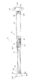
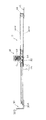
本発明の実施の形態を図面を参照して詳細に述べると、図1乃至図5は、本発明の1つの実施の形態による伸縮ステー10を示す。この伸縮ステー10は、内側アーム12とこの内側アーム12が摺動自在に嵌合された外側アーム14とを含むステー本体16と、このステー本体16の内外のアーム12、14を所定の重合位置でロックするロック手段18とを備えている。内外のアーム12、14は、ステンレスその他の適宜の金属材料から作られる。
An embodiment of the present invention will be described in detail with reference to the drawings. FIGS. 1 to 5 show a
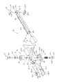
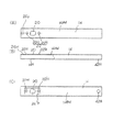
図示の例では、内側アーム12は、図4から解るように、断面略U字形の形態を有し、その上側開口部には内側に向けて水平に延びる突縁12aを有するが、非取付端(図4の右端)では上側が符号12bに示すように閉じられている。また、外側アーム14は、断面矩形の形態を有し、その一方の平板部14AWにロック手段18の後に述べる案内部材の筒部が貫通する筒貫通孔20とその両側にあって同様に後に述べる案内部材の係止突起が係止する係止孔22H、22’Hである係止部22が設けられている。図4から解るように、筒貫通孔20は、略矩形の形態を有する。
In the illustrated example, the
内側アーム12は、その閉じられた非取付端を上下から挟むように取り付けられる上下のスライダ片24P、24’Pから成るスライダ24を有し、また外側アーム14は、その非取付端(図4の左端)内に挿入されて取り付けられた上下のスライダ片26P、26’Pから成るスライダ26を有する。内側アーム12の非取付端は、スライダ24が外側アーム14の内面に係合して摺動し、また内側アーム12の他の部分は、外側アーム14内のスライダ26に係合して摺動する。従って、内側アーム12の本体は、スライダを有する部分を除いて外側アーム14の上下の平板部に接触していない状態で外側アーム14内を摺動する。なお、本明細書において「非取付端」とは、伸縮ステーが扉やこの扉によって開閉される物体に取り付けられる端ではない端を意味する。
The
スライダ片24P、24’Pは、図4及び図5に示すように、その相対する面に突起24A、24’Aを有し、これらの突起ピン24A、24’Aは、内側アーム12の取付孔24H、24’Hに圧入してスライダ片24P、24’Pを内側アーム12に固定し、またスライダ片26Pは、図4及び図5に示すように、その外面に突起26Aを有し、この突起26Aは、外側アーム14の取付孔26Hに圧入してスライダ片26Pを外側アーム14に固定し、スライダ片26’は、図4及び図5に示すように、その外面に突板部26’Aを有し、この突板部26’Aは、外側アーム14の矩形状の係止孔14H(図6参照)に係入してスライダ片26’Pを外側アーム14に固定している。なお、係止孔14Hは、後にステーの組立てに関連して述べるように、案内部材50を外側アーム14に組み込む際に案内部材50が通過する孔を兼ねている。
As shown in FIGS. 4 and 5, the
内側アーム12の取付端(図1の左端)には、例えば、図示しない収納箱の扉の如き開閉部材の背面にねじ止めされるべき略L字形のブラケット30が枢動自在に取り付けられている。更に詳細に述べると、このブラケット30は、図1及び図3から解るように、ブラケット30の取付け片30Aに設けられたピン32を内側アーム12の取付端に設けられた取付孔32Hを貫通させて内側アーム12内に突出するピン部分に座金36を嵌め、更にその上の係止溝32GにC形止め輪38を嵌めて込んで内側アーム12に枢動自在に取り付けられている。ブラケット30の固定片30Bにはねじ貫通孔30Hを有し、ブラケット30は、このねじ貫通孔30Hにねじを貫通して開閉部材にねじ止めされる。
A substantially L-
また、外側アーム14の取付端(図1の右端)には、例えば、収納箱の開口縁にねじ止めされるべき略三角形の平板状のブラケット40が枢動自在に取り付けられている。更に詳細に述べると、このブラケット40は、図1及び図2から解るように、その三角形の頂部付近に設けられたピン42を外側アーム14の他方の平板部14BWに設けられた取付孔42Hを貫通させて外側アーム14内に突出するピン部分の環状溝42Gにホルダー44を嵌め込んでこのピン42を弾性的に保持している。ホルダー44は、ピンの環状溝42Gを抱き込むC形ばね44Sとこのばね44Sを保持して外側アーム14の取付端の開口部に嵌め込むことができる嵌め込み部44Hとから成っている。ブラケット40にはねじ貫通孔40Hを有し、ブラケット40は、このねじ貫通孔40Hにねじを貫通して収納箱の開口縁にねじ止めされる。
Further, for example, a substantially triangular flat plate-
ロック手段18は、特に、図4及び図5から解るように、アーム14に取り付けられた案内部材50に配置されてロックばね52によって付勢されるロック杆54と内側アーム12に設けられ内外のアーム12、14をロックするようにロック杆54が係入するロック孔56とから成っている。ロック手段18は、更に、ロック杆54の頂部に固定されてロック杆54をロックばね52に抗してロック孔56から抜き出すための冠状の摘み58を有する。ロック孔56は、図4に示すように、ステー10の伸長状態でロック杆54が係入するように、内側アーム12の右側に設けられている。
As shown in FIGS. 4 and 5, the lock means 18 is provided on a
図4及び図5に示すように、ロック手段18の案内部材50は、外側アーム14の平板部14AWに設けられた筒貫通孔20を貫通しロック杆54を案内する筒部60とこの筒部60に一体に設けられ平板部14AWの内面に係合する基部62とから成っている。
As shown in FIGS. 4 and 5, the
案内部材50の筒部60は、図4から解るように、筒貫通孔20の形状に相応するほぼ矩形の断面の外周面を有し、従って筒部60は、筒貫通孔20を貫通して外側アーム14に取り付けられると、回り止め状態で取り付けられる。基部62は、図4から解るように、筒部60の両側から水平に延びる平板の形態を有し、その両側面には内側アーム12の突条12aが係入して内側アーム12の長手方向の移動を許す逃げ溝62Gを有する。なお、既に述べたように、案内部材50は、外側アーム14の平板部14BW側に設けられたスライダ係止用の係止孔14H(図6(B)(C)参照)を通して外側アーム14内に入り込むことができる。
As shown in FIG. 4, the cylindrical portion 60 of the
ロックばね52は、筒部60の上端に設けられた内鍔の形態のばね係止部60F(図5参照)とロック杆54の肩部54Sとの間に配置されてロック杆54を図5の下向きに付勢してロック杆54の先端部54Tをロック孔56に係入すると共に、案内部材50の筒部60を図5の上向きに付勢して基部62を外側アーム14の平板部14AWの内面に係合している。従って、案内部材50は、ロックばね54の付勢によって基部62を外側アーム14に押し付けて固定されることが解る。
The
案内部材50の基部62は、外側アーム14の平板部14AWの係止孔22H、22’Hに入り込んで係止される係止突起64、64’を有し、従って案内部材50は、筒部60と係止突起64、64’とが外側アーム14の平板部14AWに係止してロックばね54による付勢と相俟って外側アーム14に確実に固定される。なお、図示の形態では、案内部材50の係止突起64、64’が係入する係止部22が係止孔22H、22’Hであったが、これは係止突起64、64’が係入する係止溝であってもよい。
The base portion 62 of the
摘み58は、案内部材50の筒部60に被せられるようにしてロック杆54に取り付けられている。更に詳細に述べると、摘み58は、図5及び図7に示すように、その内部に中壁66を有し、頭付きボルト68は、この中壁66のボルト貫通孔66Hを貫通してロック杆54にねじ込まれて摘み58をロック杆54に固定している。キャップ70は、摘み58の頂部のへこみ58Rに位置する頭付きボルト68の頭部を隠蔽するように摘み58のへこみ58Rに係入して被せられる。なお、図5において、符号72、72’は、摘み58の中壁66とロック杆54の頭部との間及び中壁66と頭付きボルト68の頭部との間にそれぞれ挿入された座金、また符号74は、頭付きボルト68が中壁66を貫通する部分に配置されたスペーサである。
The
次に、本発明の伸縮ステーの組み立て方法を述べると、図4に示すように、案内部材50を外側アーム14のスライダ係止用の係止孔14Hを通して外側アーム14に入り込ませ、この案内部材50の筒部60内にロックばね52とロック杆54とを挿入する。
Next, a method for assembling the telescopic stay according to the present invention will be described. As shown in FIG. 4, the
摘み58の中壁66のボルト貫通孔66Hにスペーサ74を挿入し、頭付きボルト68をこのボルト貫通孔66Hに貫通し、ロック杆54を座金72、72’で挟んで摘み58を案内部材50の筒部60に被せ、頭付きボルト68をロック杆54に締め込んで摘み58をロック杆54に取り付けると共に案内部材50の基部62を外側アーム14の平板部14AWの内面に押し付ける。なお、摘み58のへこみ58Rは、キャップ70を押し込んで隠蔽する。
The
次いで、摘み58によってロック杆54をロック孔56から解除しながら下スライダ片26’Pをその突板部26’Aが係止孔14Hに係入されるまで引き込み、その後上スライダ片26を押し込む。図5に示すように、上スライダ片26の係止突起26Aは、押し込み方向に次第に上向きに傾斜する傾斜面26ASを有するので、上スライダ片26Pは、この傾斜面26ASに沿って押し下げられながら押し込まれて係止突起26Aが係止孔26Hに相対すると、係止突起26Aが係止孔26Hに嵌まり込み、上下のスライダ片26P、26’Pが外側アーム14に固定される。摘み58を解放すると、ロック杆54は、下スライダ片26’のロック杆逃げ孔26’hに係入するが、この逃げ孔26’hは、設けなくてもよい。
Next, while releasing the
内側アーム12の非取付端に上下のスライダ片24P、24’Pを取り付けた後、外側アーム14の取付端側の開口から内側アーム12を引き入れ、その取付端を外側アーム14の非取付端の開口から引き出す(図1参照)。この作業は、摘み58をロック解除の方向に持ち上げながら行われる。
After the upper and
次いで、内側アーム12の取付端にブラケット30を取付け、また外側アーム14の取付端にブラケット40を取り付けて伸縮ステー10の組み立てを完了する。
Next, the
この伸縮ステー10は、例えば、ブラケット30及び40を収納箱の蓋と箱本体にそれぞれねじ止めして収納箱に使用することができる。伸縮ステー10の内側アーム12を引き出して伸縮ステー10を伸長しながら蓋を開くことができ、この開放状態を維持するために、摘み58を解放すると、ロック杆54がロックばね52によってロック孔56に係入してこの伸張状態を維持する。蓋を閉じるときには、摘み58をロックばね52に抗して持ち上げて内側アーム12を引き込みながら蓋を閉じる。
The
本発明の伸縮ステー10は、ロック手段18の案内部材50が外側アーム14の平板部14AWの内面に係合する基部62を有していて、ロック杆54を付勢するロックばね52がこの案内部材50の基部62が平板部14AWの内面に係合するように案内部材50を付勢しているので、ロックばね52が案内部材50を外側アーム14に固定する機能を有する。従って、案内部材50を外側アーム14に固定する特別の手段を必要としないことが解る。
In the
なお、上記の実施の形態では、基部62に筒部60が一体に設けられているが、基部62自体の孔がロック杆54の案内機能を有するので、外側アーム14の平板部14AWを貫通する筒部50を有していなくともよい。
In the above-described embodiment, the cylindrical portion 60 is provided integrally with the base portion 62. However, since the hole of the base portion 62 itself has a guide function for the
本発明は、ロック杆をロック孔に係入するように付勢するロックばねがこのロック杆を案内する案内部材を外側アームの内面に押し付けて固定する機能を有するので、案内部材を外側アームに固定する特別の手段を必要とすることがなく、組み立てが容易であり、産業上の利用性が高いことが解る。 In the present invention, the lock spring that urges the lock rod to engage with the lock hole has a function of pressing and fixing the guide member that guides the lock rod against the inner surface of the outer arm. It can be seen that no special means for fixing is required, the assembly is easy, and the industrial applicability is high.
10 伸縮ステー
12 内側アーム
12a 内側アームの突縁
12b 内側アームの閉じ部
14 外側アーム
14H 係止孔
14AW 外側アームの一方の平板部
14BW 外側アームの他方の平板部
16 ステー本体
18 ロック手段
20 筒貫通孔
22 係止部
22H、22’H 係止孔
24 スライダ
24P、24’P 上下のスライダ片
24A、24’A 突起ピン
24H、24’H 取付孔
26 スライダ
26P、26’P 上下のスライダ片
26A スライダ片26Pの突起
26AS 突起の傾斜面
26H、26’H 外側アームの取付孔
26’A スライダ片26’Pの突板部
26’h 下スライダ片のロック杆の逃げ孔
30 ブラケット
30A 取付け片
30H ねじ貫通孔
32 ピン
34 取付孔
32G 係止溝
36 座金
38 C形止め輪
40 ブラケット
40H ねじ貫通孔
42 ピン
42G 環状溝
44 ホルダー
44S C形ばね
44H 嵌め込み部
50 案内部材
52 ロックばね
54 ロック杆
54S 肩部
56、56A、56B ロック孔
58 冠状の摘み
58R へこみ
60 筒部
60F ばね係止部
62 基部
62G 逃げ溝
64、64’ 係止突起
66 中壁
66H ボルト貫通孔
68 頭付きボルト
70 キャップ
72、72’ 座金
74 スペーサ
DESCRIPTION OF
Claims (6)
前記外側アームがその長さ方向にわたる平板部を有するものであること、
前記外側アームに摺動自在に嵌合された前記内側アームが当該外側アームの内面に内接していること、
前記ロック手段の案内部材が、前記外側アームの平板部の内面に係合するものであって前記内側アーム内に介在される基部を備えていること、
前記内側アームの内部に嵌め込まれた前記案内部材の基部が前記外側アーム平板部内面に係合し、かつ、前記内側アームが前記案内部材の基部と前記外側アームとの隙間内に介在してその外側アーム内を摺動自在であること、および、
前記案内部材の基部が前記外側アームの平板部の内面と係合するように前記ロックばねがその案内部材を更に付勢していること
を特徴とする伸縮ステー。 A stay main body including an inner arm and an outer arm that is slidably fitted to the inner arm, and a locking means for locking the arms of the inner and outer side of the stay main body at a predetermined overlapping position, locking means of which, be one and the lock rod which is disposed in the guide member attached to the outer arm is biased by the lock spring, the lock lever to lock the arms of the inner and outer side engaging entering inside In the telescopic stay having a lock hole provided in the arm ,
The outer arm has a flat plate portion extending in the length direction thereof;
The inner arm slidably fitted to the outer arm is inscribed in the inner surface of the outer arm;
Said guide member of the locking means comprises a base portion which is interposed between the said inner arm be one that engages the inner surface of the flat plate portion of the outer arm,
The base portion of the guide member fitted inside the inner arm engages the inner surface of the outer arm flat plate portion, and the inner arm is interposed in the gap between the base portion of the guide member and the outer arm. Slidable within the outer arm, and
Telescopic stay, characterized in that said lock spring is further biases the guide member so as the base of the guide member is an inner surface engages the flat portion of the outer arm.
前記外側アームがその長さ方向にわたる平板部を有するものであること、
前記外側アームに摺動自在に嵌合された前記内側アームが当該外側アームの内面に内接していること、
前記ロック手段の案内部材が、前記外側アームの平板部を貫通することのできる筒部と、この筒部に設けられて外側アームの平板部の内面に係合する基部とを備え、かつ、その基部が前記内側アーム内に介在されるものであること、
前記内側アームの内部に嵌め込まれた前記案内部材について、この案内部材の筒部が前記外側アームの平板部を貫通し、かつ、この案内部材の基部が前記外側アームの平板部内面に係合し、しかも、前記内側アームが案内部材の基部と前記外側アームとの隙間内に介在してその外側アーム内を摺動自在であること、および、
前記案内部材の基部が前記外側アームの平板部の内面と係合するように前記ロックばねがその案内部材を更に付勢していること
を特徴とする伸縮ステー。 A stay main body including an inner arm and an outer arm that is slidably fitted to the inner arm, and a locking means for locking the arms of the inner and outer side of the stay main body at a predetermined overlapping position, locking means of which, be one and the lock rod which is disposed in the guide member attached to the outer arm is biased by the lock spring, the lock lever to lock the arms of the inner and outer side engaging entering inside In the telescopic stay having a lock hole provided in the arm ,
The outer arm has a flat plate portion extending in the length direction thereof;
The inner arm slidably fitted to the outer arm is inscribed in the inner surface of the outer arm;
The guide member of the locking means comprise a cylindrical portion capable of penetrating the flat plate portion of said outer arm, and a base portion which engages the inner surface of the flat plate portion of the outer arm is provided on the cylindrical portion, and that A base is interposed in the inner arm;
With respect to the guide member fitted inside the inner arm, the cylindrical portion of the guide member penetrates the flat plate portion of the outer arm, and the base portion of the guide member engages with the inner surface of the flat plate portion of the outer arm. Moreover, the inner arm is slidable in the outer arm by being interposed in the gap between the base portion of the guide member and the outer arm, and
Telescopic stay, characterized in that said lock spring is further biases the guide member so as the base of the guide member is an inner surface engages the flat portion of the outer arm.
6. The telescopic stay according to claim 2, wherein the cylindrical portion of the guide member has a spring engaging portion with which an upper end of the spring is engaged.
Priority Applications (4)
| Application Number | Priority Date | Filing Date | Title |
|---|---|---|---|
| JP2004177391A JP4146396B2 (en) | 2004-06-15 | 2004-06-15 | Telescopic stay |
| PCT/JP2005/010828 WO2005124076A1 (en) | 2004-06-15 | 2005-06-14 | Telescopic stay |
| CNB2005800198384A CN100441826C (en) | 2004-06-15 | 2005-06-14 | Telescopic stay |
| US11/570,363 US7497490B2 (en) | 2004-06-15 | 2005-06-14 | Telescopic stay |
Applications Claiming Priority (1)
| Application Number | Priority Date | Filing Date | Title |
|---|---|---|---|
| JP2004177391A JP4146396B2 (en) | 2004-06-15 | 2004-06-15 | Telescopic stay |
Publications (2)
| Publication Number | Publication Date |
|---|---|
| JP2006002370A JP2006002370A (en) | 2006-01-05 |
| JP4146396B2 true JP4146396B2 (en) | 2008-09-10 |
Family
ID=35509726
Family Applications (1)
| Application Number | Title | Priority Date | Filing Date |
|---|---|---|---|
| JP2004177391A Expired - Fee Related JP4146396B2 (en) | 2004-06-15 | 2004-06-15 | Telescopic stay |
Country Status (4)
| Country | Link |
|---|---|
| US (1) | US7497490B2 (en) |
| JP (1) | JP4146396B2 (en) |
| CN (1) | CN100441826C (en) |
| WO (1) | WO2005124076A1 (en) |
Families Citing this family (14)
| Publication number | Priority date | Publication date | Assignee | Title |
|---|---|---|---|---|
| CN2875721Y (en) * | 2006-01-26 | 2007-03-07 | 苏州飞华铝制工业有限公司 | Elastic pin location type expansion table |
| TWI456614B (en) | 2011-12-05 | 2014-10-11 | Giga Byte Tech Co Ltd | Input device and manufacturing method thereof |
| US8683657B2 (en) * | 2012-08-29 | 2014-04-01 | Thomas Lin | Press button-controlled retractable bar |
| US9284751B2 (en) * | 2013-06-05 | 2016-03-15 | Chanell Commercial Corp. | High security locking assembly for above-ground fiber optic/cable network enclosures |
| US20160060912A1 (en) * | 2014-09-02 | 2016-03-03 | David Mark Matthews | Vehicle Lock And Personal Protection Baton |
| CN104863442B (en) * | 2015-05-11 | 2017-05-10 | 李增榜 | Telescopic wind brace |
| US10954704B2 (en) * | 2016-08-25 | 2021-03-23 | Greenlee Tools, Inc. | Door stop mechanism for holding a door of an enclosure in an open position |
| FR3057007B1 (en) * | 2016-10-05 | 2019-05-10 | Cosnet | DOOR OPENING ADJUSTMENT DEVICE AND TRANSPORT VEHICLE OF THE BETAILLERE TYPE COMPRISING SUCH A DEVICE |
| US10512180B2 (en) * | 2017-05-17 | 2019-12-17 | Commscope Technologies Llc | Security system for electronics cabinet |
| US10920468B2 (en) * | 2017-06-02 | 2021-02-16 | Martasz Smith | Window lock |
| US10815708B2 (en) * | 2017-07-06 | 2020-10-27 | Porter Systems | Positioner mechanism using linear adjusting lock |
| CN108678579A (en) * | 2018-05-10 | 2018-10-19 | 湖南省金为新材料科技有限公司 | A kind of telescopic door and window closer and door and window that a key is closed |
| JP7176696B2 (en) * | 2019-03-22 | 2022-11-22 | マツ六株式会社 | door moving device |
| US11965376B2 (en) * | 2022-02-21 | 2024-04-23 | Textron Innovations Inc. | Hinged door open plunger |
Family Cites Families (18)
| Publication number | Priority date | Publication date | Assignee | Title |
|---|---|---|---|---|
| US1599971A (en) * | 1924-03-17 | 1926-09-14 | Melson Frank | Telescopic casement stay |
| US1581185A (en) * | 1925-10-06 | 1926-04-20 | Horace R Ellis | Fastener for sectional window screens |
| US1954739A (en) * | 1932-06-11 | 1934-04-10 | Reading Hardware Corp | Transom lifter |
| USD244004S (en) * | 1975-11-13 | 1977-04-12 | Elkhart Rivet & Register Co., Inc. | Double acting door lift and closing device |
| US4385849A (en) * | 1981-02-02 | 1983-05-31 | Crain Enterprises, Inc. | Extensible and retractable rod |
| US4409866A (en) * | 1981-12-28 | 1983-10-18 | Mcbride Joan | Tool handle with contoured through passageway and spring biased trigger |
| DE3630307A1 (en) * | 1986-09-08 | 1988-03-17 | Tsuruta Yuzo | EXTENDABLE TRIPOD |
| US5102173A (en) * | 1989-07-28 | 1992-04-07 | Schallern John R | Reenforcer for doors and windows |
| JPH07317415A (en) * | 1994-05-26 | 1995-12-05 | Shin Nikkei Co Ltd | Window opening control device |
| JPH08144630A (en) * | 1994-11-22 | 1996-06-04 | Shinkansai Bearing Kk | Adjuster for quantity of opening |
| JPH08184255A (en) * | 1994-12-28 | 1996-07-16 | Yamazaki Sangyo Kk | Regulator for vertical axis pivoted window |
| US6079894A (en) * | 1996-06-13 | 2000-06-27 | Invacare Corporation | Integral snap button and anti-rattle member |
| US6352290B1 (en) * | 2000-04-18 | 2002-03-05 | Anthony C. Scottino | Child safety lock |
| US6854916B2 (en) * | 2002-05-17 | 2005-02-15 | David Hsieh | Retractable rod assembly |
| CN2591170Y (en) * | 2002-12-13 | 2003-12-10 | 广州市兆鹰五金有限公司 | Sash fastener |
| US6883208B1 (en) * | 2003-03-28 | 2005-04-26 | Yao-Chung Huang | Hedge shear extendable handle enhanced structure |
| US20060062632A1 (en) * | 2004-09-17 | 2006-03-23 | Norstar Trade, Inc. | Release pin assembly for tents and canopies |
| US20070003361A1 (en) * | 2005-07-01 | 2007-01-04 | Shu-Mei Wang | Locking device for a telescopic tube |
-
2004
- 2004-06-15 JP JP2004177391A patent/JP4146396B2/en not_active Expired - Fee Related
-
2005
- 2005-06-14 US US11/570,363 patent/US7497490B2/en not_active Expired - Fee Related
- 2005-06-14 CN CNB2005800198384A patent/CN100441826C/en not_active Expired - Fee Related
- 2005-06-14 WO PCT/JP2005/010828 patent/WO2005124076A1/en active Application Filing
Also Published As
| Publication number | Publication date |
|---|---|
| CN1969106A (en) | 2007-05-23 |
| JP2006002370A (en) | 2006-01-05 |
| US7497490B2 (en) | 2009-03-03 |
| CN100441826C (en) | 2008-12-10 |
| WO2005124076A1 (en) | 2005-12-29 |
| US20080042449A1 (en) | 2008-02-21 |
Similar Documents
| Publication | Publication Date | Title |
|---|---|---|
| JP4146396B2 (en) | Telescopic stay | |
| JP5718931B2 (en) | Slider for slide fastener | |
| US7798581B2 (en) | Fast detachable slide bracket | |
| US5462380A (en) | Detent | |
| JP4152254B2 (en) | Slider for slide fastener | |
| JPH10313910A (en) | Slider for slide fastener | |
| JPWO2011078358A1 (en) | Slider for slide fastener | |
| US9403420B2 (en) | Sun visor holder | |
| JP5254128B2 (en) | End plate fixing bracket | |
| US6092436A (en) | Anchorage for motion-transmitting cable assembly | |
| WO2017110679A1 (en) | Device adapted for mounting through wall | |
| JP2007076262A (en) | Binding implement | |
| KR101929683B1 (en) | Locking device for windows and doors | |
| JP4946825B2 (en) | Sliding door stopper | |
| JP2005045915A (en) | Saddle | |
| JP3073478B2 (en) | File | |
| JP7406954B2 (en) | Installation device for vehicle interior parts | |
| JP5908219B2 (en) | Tension member fixture | |
| JP3105624U (en) | Door stopper device for switchboard etc. | |
| JP6571049B2 (en) | Parking brake device and tension detection unit | |
| JP4179656B2 (en) | Long body support | |
| JP2008006884A (en) | Assist grip | |
| JP3148917U (en) | Spring type inspection palate | |
| US1998730A (en) | Hood catch | |
| JP2015224725A (en) | Holding device |
Legal Events
| Date | Code | Title | Description |
|---|---|---|---|
| A621 | Written request for application examination |
Free format text: JAPANESE INTERMEDIATE CODE: A621 Effective date: 20060922 |
|
| A131 | Notification of reasons for refusal |
Free format text: JAPANESE INTERMEDIATE CODE: A131 Effective date: 20080325 |
|
| A521 | Request for written amendment filed |
Free format text: JAPANESE INTERMEDIATE CODE: A523 Effective date: 20080526 |
|
| TRDD | Decision of grant or rejection written | ||
| A01 | Written decision to grant a patent or to grant a registration (utility model) |
Free format text: JAPANESE INTERMEDIATE CODE: A01 Effective date: 20080617 |
|
| A01 | Written decision to grant a patent or to grant a registration (utility model) |
Free format text: JAPANESE INTERMEDIATE CODE: A01 |
|
| A61 | First payment of annual fees (during grant procedure) |
Free format text: JAPANESE INTERMEDIATE CODE: A61 Effective date: 20080619 |
|
| R150 | Certificate of patent or registration of utility model |
Free format text: JAPANESE INTERMEDIATE CODE: R150 Ref document number: 4146396 Country of ref document: JP Free format text: JAPANESE INTERMEDIATE CODE: R150 |
|
| FPAY | Renewal fee payment (event date is renewal date of database) |
Free format text: PAYMENT UNTIL: 20110627 Year of fee payment: 3 |
|
| FPAY | Renewal fee payment (event date is renewal date of database) |
Free format text: PAYMENT UNTIL: 20110627 Year of fee payment: 3 |
|
| FPAY | Renewal fee payment (event date is renewal date of database) |
Free format text: PAYMENT UNTIL: 20120627 Year of fee payment: 4 |
|
| FPAY | Renewal fee payment (event date is renewal date of database) |
Free format text: PAYMENT UNTIL: 20130627 Year of fee payment: 5 |
|
| LAPS | Cancellation because of no payment of annual fees |