EP1602385B1 - Blutsammlungsgerät - Google Patents
Blutsammlungsgerät Download PDFInfo
- Publication number
- EP1602385B1 EP1602385B1 EP05017226A EP05017226A EP1602385B1 EP 1602385 B1 EP1602385 B1 EP 1602385B1 EP 05017226 A EP05017226 A EP 05017226A EP 05017226 A EP05017226 A EP 05017226A EP 1602385 B1 EP1602385 B1 EP 1602385B1
- Authority
- EP
- European Patent Office
- Prior art keywords
- blood
- tube
- blood collecting
- bag
- duct
- Prior art date
- Legal status (The legal status is an assumption and is not a legal conclusion. Google has not performed a legal analysis and makes no representation as to the accuracy of the status listed.)
- Expired - Lifetime
Links
- 210000004369 blood Anatomy 0.000 title claims description 640
- 239000008280 blood Substances 0.000 title claims description 631
- 238000007789 sealing Methods 0.000 claims description 54
- 229920005989 resin Polymers 0.000 claims description 34
- 239000011347 resin Substances 0.000 claims description 34
- 230000003139 buffering effect Effects 0.000 claims description 7
- 230000002265 prevention Effects 0.000 claims description 2
- 238000005070 sampling Methods 0.000 description 69
- 239000000463 material Substances 0.000 description 40
- 238000010276 construction Methods 0.000 description 25
- 238000000034 method Methods 0.000 description 19
- 229920000915 polyvinyl chloride Polymers 0.000 description 19
- 239000004800 polyvinyl chloride Substances 0.000 description 19
- 239000007788 liquid Substances 0.000 description 15
- 241000894006 Bacteria Species 0.000 description 14
- 206010018910 Haemolysis Diseases 0.000 description 13
- 230000000052 comparative effect Effects 0.000 description 13
- 230000008588 hemolysis Effects 0.000 description 13
- 229920001971 elastomer Polymers 0.000 description 12
- 239000005060 rubber Substances 0.000 description 12
- 230000002349 favourable effect Effects 0.000 description 10
- 239000007787 solid Substances 0.000 description 10
- 230000017531 blood circulation Effects 0.000 description 9
- 239000000306 component Substances 0.000 description 8
- 210000003743 erythrocyte Anatomy 0.000 description 8
- -1 polyethylene Polymers 0.000 description 8
- 210000003462 vein Anatomy 0.000 description 6
- 239000003146 anticoagulant agent Substances 0.000 description 5
- 238000010241 blood sampling Methods 0.000 description 5
- 210000004204 blood vessel Anatomy 0.000 description 5
- 239000012528 membrane Substances 0.000 description 5
- 238000012360 testing method Methods 0.000 description 5
- 229940127090 anticoagulant agent Drugs 0.000 description 4
- BJQHLKABXJIVAM-UHFFFAOYSA-N bis(2-ethylhexyl) phthalate Chemical compound CCCCC(CC)COC(=O)C1=CC=CC=C1C(=O)OCC(CC)CCCC BJQHLKABXJIVAM-UHFFFAOYSA-N 0.000 description 4
- 210000000601 blood cell Anatomy 0.000 description 4
- 239000012503 blood component Substances 0.000 description 4
- 238000004891 communication Methods 0.000 description 4
- 230000004927 fusion Effects 0.000 description 4
- 230000002949 hemolytic effect Effects 0.000 description 4
- 210000002966 serum Anatomy 0.000 description 4
- 244000043261 Hevea brasiliensis Species 0.000 description 3
- 239000005062 Polybutadiene Substances 0.000 description 3
- 239000004698 Polyethylene Substances 0.000 description 3
- 229920006311 Urethane elastomer Polymers 0.000 description 3
- 229920000800 acrylic rubber Polymers 0.000 description 3
- 229920005549 butyl rubber Polymers 0.000 description 3
- 230000000694 effects Effects 0.000 description 3
- 239000001963 growth medium Substances 0.000 description 3
- 230000036512 infertility Effects 0.000 description 3
- 229920003049 isoprene rubber Polymers 0.000 description 3
- 229920003052 natural elastomer Polymers 0.000 description 3
- 229920001194 natural rubber Polymers 0.000 description 3
- 230000002093 peripheral effect Effects 0.000 description 3
- 239000004014 plasticizer Substances 0.000 description 3
- 229920000058 polyacrylate Polymers 0.000 description 3
- 229920002857 polybutadiene Polymers 0.000 description 3
- 229920000515 polycarbonate Polymers 0.000 description 3
- 239000004417 polycarbonate Substances 0.000 description 3
- 229920000573 polyethylene Polymers 0.000 description 3
- 229920002379 silicone rubber Polymers 0.000 description 3
- 239000004945 silicone rubber Substances 0.000 description 3
- 229920003048 styrene butadiene rubber Polymers 0.000 description 3
- 208000035473 Communicable disease Diseases 0.000 description 2
- NBIIXXVUZAFLBC-UHFFFAOYSA-N Phosphoric acid Chemical compound OP(O)(O)=O NBIIXXVUZAFLBC-UHFFFAOYSA-N 0.000 description 2
- 239000004743 Polypropylene Substances 0.000 description 2
- 210000004027 cell Anatomy 0.000 description 2
- 238000012258 culturing Methods 0.000 description 2
- 230000006837 decompression Effects 0.000 description 2
- 230000007423 decrease Effects 0.000 description 2
- 239000011521 glass Substances 0.000 description 2
- 208000015181 infectious disease Diseases 0.000 description 2
- 239000000203 mixture Substances 0.000 description 2
- 210000002381 plasma Anatomy 0.000 description 2
- 229920000728 polyester Polymers 0.000 description 2
- 229920001155 polypropylene Polymers 0.000 description 2
- 229920001343 polytetrafluoroethylene Polymers 0.000 description 2
- 239000004810 polytetrafluoroethylene Substances 0.000 description 2
- 230000001954 sterilising effect Effects 0.000 description 2
- 238000004659 sterilization and disinfection Methods 0.000 description 2
- 229920001169 thermoplastic Polymers 0.000 description 2
- 229920002725 thermoplastic elastomer Polymers 0.000 description 2
- 239000004416 thermosoftening plastic Substances 0.000 description 2
- 208000030507 AIDS Diseases 0.000 description 1
- QTBSBXVTEAMEQO-UHFFFAOYSA-M Acetate Chemical compound CC([O-])=O QTBSBXVTEAMEQO-UHFFFAOYSA-M 0.000 description 1
- 239000004803 Di-2ethylhexylphthalate Substances 0.000 description 1
- PGIBJVOPLXHHGS-UHFFFAOYSA-N Di-n-decyl phthalate Chemical compound CCCCCCCCCCOC(=O)C1=CC=CC=C1C(=O)OCCCCCCCCCC PGIBJVOPLXHHGS-UHFFFAOYSA-N 0.000 description 1
- MQIUGAXCHLFZKX-UHFFFAOYSA-N Di-n-octyl phthalate Natural products CCCCCCCCOC(=O)C1=CC=CC=C1C(=O)OCCCCCCCC MQIUGAXCHLFZKX-UHFFFAOYSA-N 0.000 description 1
- LFQSCWFLJHTTHZ-UHFFFAOYSA-N Ethanol Chemical compound CCO LFQSCWFLJHTTHZ-UHFFFAOYSA-N 0.000 description 1
- DGAQECJNVWCQMB-PUAWFVPOSA-M Ilexoside XXIX Chemical compound C[C@@H]1CC[C@@]2(CC[C@@]3(C(=CC[C@H]4[C@]3(CC[C@@H]5[C@@]4(CC[C@@H](C5(C)C)OS(=O)(=O)[O-])C)C)[C@@H]2[C@]1(C)O)C)C(=O)O[C@H]6[C@@H]([C@H]([C@@H]([C@H](O6)CO)O)O)O.[Na+] DGAQECJNVWCQMB-PUAWFVPOSA-M 0.000 description 1
- 239000004952 Polyamide Substances 0.000 description 1
- ZLMJMSJWJFRBEC-UHFFFAOYSA-N Potassium Chemical compound [K] ZLMJMSJWJFRBEC-UHFFFAOYSA-N 0.000 description 1
- 206010040047 Sepsis Diseases 0.000 description 1
- 241000700605 Viruses Species 0.000 description 1
- 241000607447 Yersinia enterocolitica Species 0.000 description 1
- 230000002411 adverse Effects 0.000 description 1
- 239000000956 alloy Substances 0.000 description 1
- 229910045601 alloy Inorganic materials 0.000 description 1
- 229910000147 aluminium phosphate Inorganic materials 0.000 description 1
- 229940127219 anticoagulant drug Drugs 0.000 description 1
- 238000005452 bending Methods 0.000 description 1
- 230000000903 blocking effect Effects 0.000 description 1
- 210000001754 blood buffy coat Anatomy 0.000 description 1
- 238000007664 blowing Methods 0.000 description 1
- 210000004556 brain Anatomy 0.000 description 1
- FACXGONDLDSNOE-UHFFFAOYSA-N buta-1,3-diene;styrene Chemical compound C=CC=C.C=CC1=CC=CC=C1.C=CC1=CC=CC=C1 FACXGONDLDSNOE-UHFFFAOYSA-N 0.000 description 1
- 239000003795 chemical substances by application Substances 0.000 description 1
- 239000011248 coating agent Substances 0.000 description 1
- 238000000576 coating method Methods 0.000 description 1
- 238000011109 contamination Methods 0.000 description 1
- 238000007796 conventional method Methods 0.000 description 1
- 229920001577 copolymer Polymers 0.000 description 1
- 239000013013 elastic material Substances 0.000 description 1
- 239000005038 ethylene vinyl acetate Substances 0.000 description 1
- 239000004744 fabric Substances 0.000 description 1
- 239000012530 fluid Substances 0.000 description 1
- 239000012634 fragment Substances 0.000 description 1
- 229920000669 heparin Polymers 0.000 description 1
- ZFGMDIBRIDKWMY-PASTXAENSA-N heparin Chemical compound CC(O)=N[C@@H]1[C@@H](O)[C@H](O)[C@@H](COS(O)(=O)=O)O[C@@H]1O[C@@H]1[C@@H](C(O)=O)O[C@@H](O[C@H]2[C@@H]([C@@H](OS(O)(=O)=O)[C@@H](O[C@@H]3[C@@H](OC(O)[C@H](OS(O)(=O)=O)[C@H]3O)C(O)=O)O[C@@H]2O)CS(O)(=O)=O)[C@H](O)[C@H]1O ZFGMDIBRIDKWMY-PASTXAENSA-N 0.000 description 1
- 229960001008 heparin sodium Drugs 0.000 description 1
- 208000006454 hepatitis Diseases 0.000 description 1
- 231100000283 hepatitis Toxicity 0.000 description 1
- 238000001802 infusion Methods 0.000 description 1
- 238000004519 manufacturing process Methods 0.000 description 1
- 230000007935 neutral effect Effects 0.000 description 1
- 230000000149 penetrating effect Effects 0.000 description 1
- 230000035515 penetration Effects 0.000 description 1
- 229920002647 polyamide Polymers 0.000 description 1
- 229920001225 polyester resin Polymers 0.000 description 1
- 239000004645 polyester resin Substances 0.000 description 1
- 229920000642 polymer Polymers 0.000 description 1
- 229920002959 polymer blend Polymers 0.000 description 1
- 229910052700 potassium Inorganic materials 0.000 description 1
- 239000011591 potassium Substances 0.000 description 1
- 230000000452 restraining effect Effects 0.000 description 1
- 229920002050 silicone resin Polymers 0.000 description 1
- 239000012748 slip agent Substances 0.000 description 1
- 229910052708 sodium Inorganic materials 0.000 description 1
- 239000011734 sodium Substances 0.000 description 1
- 229920000468 styrene butadiene styrene block copolymer Polymers 0.000 description 1
- 239000000725 suspension Substances 0.000 description 1
- 238000003856 thermoforming Methods 0.000 description 1
- 229920002554 vinyl polymer Polymers 0.000 description 1
- 230000000007 visual effect Effects 0.000 description 1
- 229940098232 yersinia enterocolitica Drugs 0.000 description 1
Images





Classifications
-
- A—HUMAN NECESSITIES
- A61—MEDICAL OR VETERINARY SCIENCE; HYGIENE
- A61M—DEVICES FOR INTRODUCING MEDIA INTO, OR ONTO, THE BODY; DEVICES FOR TRANSDUCING BODY MEDIA OR FOR TAKING MEDIA FROM THE BODY; DEVICES FOR PRODUCING OR ENDING SLEEP OR STUPOR
- A61M1/00—Suction or pumping devices for medical purposes; Devices for carrying-off, for treatment of, or for carrying-over, body-liquids; Drainage systems
- A61M1/02—Blood transfusion apparatus
- A61M1/0209—Multiple bag systems for separating or storing blood components
-
- A—HUMAN NECESSITIES
- A61—MEDICAL OR VETERINARY SCIENCE; HYGIENE
- A61M—DEVICES FOR INTRODUCING MEDIA INTO, OR ONTO, THE BODY; DEVICES FOR TRANSDUCING BODY MEDIA OR FOR TAKING MEDIA FROM THE BODY; DEVICES FOR PRODUCING OR ENDING SLEEP OR STUPOR
- A61M1/00—Suction or pumping devices for medical purposes; Devices for carrying-off, for treatment of, or for carrying-over, body-liquids; Drainage systems
- A61M1/02—Blood transfusion apparatus
- A61M1/0209—Multiple bag systems for separating or storing blood components
- A61M1/0231—Multiple bag systems for separating or storing blood components with gas separating means, e.g. air outlet through microporous membrane or gas bag
-
- A—HUMAN NECESSITIES
- A61—MEDICAL OR VETERINARY SCIENCE; HYGIENE
- A61M—DEVICES FOR INTRODUCING MEDIA INTO, OR ONTO, THE BODY; DEVICES FOR TRANSDUCING BODY MEDIA OR FOR TAKING MEDIA FROM THE BODY; DEVICES FOR PRODUCING OR ENDING SLEEP OR STUPOR
- A61M1/00—Suction or pumping devices for medical purposes; Devices for carrying-off, for treatment of, or for carrying-over, body-liquids; Drainage systems
- A61M1/02—Blood transfusion apparatus
- A61M1/0209—Multiple bag systems for separating or storing blood components
- A61M1/0236—Multiple bag systems for separating or storing blood components with sampling means, e.g. sample bag or sampling port
-
- A—HUMAN NECESSITIES
- A61—MEDICAL OR VETERINARY SCIENCE; HYGIENE
- A61J—CONTAINERS SPECIALLY ADAPTED FOR MEDICAL OR PHARMACEUTICAL PURPOSES; DEVICES OR METHODS SPECIALLY ADAPTED FOR BRINGING PHARMACEUTICAL PRODUCTS INTO PARTICULAR PHYSICAL OR ADMINISTERING FORMS; DEVICES FOR ADMINISTERING FOOD OR MEDICINES ORALLY; BABY COMFORTERS; DEVICES FOR RECEIVING SPITTLE
- A61J1/00—Containers specially adapted for medical or pharmaceutical purposes
- A61J1/05—Containers specially adapted for medical or pharmaceutical purposes for collecting, storing or administering blood, plasma or medical fluids ; Infusion or perfusion containers
- A61J1/10—Bag-type containers
-
- A—HUMAN NECESSITIES
- A61—MEDICAL OR VETERINARY SCIENCE; HYGIENE
- A61J—CONTAINERS SPECIALLY ADAPTED FOR MEDICAL OR PHARMACEUTICAL PURPOSES; DEVICES OR METHODS SPECIALLY ADAPTED FOR BRINGING PHARMACEUTICAL PRODUCTS INTO PARTICULAR PHYSICAL OR ADMINISTERING FORMS; DEVICES FOR ADMINISTERING FOOD OR MEDICINES ORALLY; BABY COMFORTERS; DEVICES FOR RECEIVING SPITTLE
- A61J1/00—Containers specially adapted for medical or pharmaceutical purposes
- A61J1/05—Containers specially adapted for medical or pharmaceutical purposes for collecting, storing or administering blood, plasma or medical fluids ; Infusion or perfusion containers
- A61J1/10—Bag-type containers
- A61J1/12—Bag-type containers with means for holding samples of contents
-
- A—HUMAN NECESSITIES
- A61—MEDICAL OR VETERINARY SCIENCE; HYGIENE
- A61J—CONTAINERS SPECIALLY ADAPTED FOR MEDICAL OR PHARMACEUTICAL PURPOSES; DEVICES OR METHODS SPECIALLY ADAPTED FOR BRINGING PHARMACEUTICAL PRODUCTS INTO PARTICULAR PHYSICAL OR ADMINISTERING FORMS; DEVICES FOR ADMINISTERING FOOD OR MEDICINES ORALLY; BABY COMFORTERS; DEVICES FOR RECEIVING SPITTLE
- A61J1/00—Containers specially adapted for medical or pharmaceutical purposes
- A61J1/14—Details; Accessories therefor
-
- A—HUMAN NECESSITIES
- A61—MEDICAL OR VETERINARY SCIENCE; HYGIENE
- A61J—CONTAINERS SPECIALLY ADAPTED FOR MEDICAL OR PHARMACEUTICAL PURPOSES; DEVICES OR METHODS SPECIALLY ADAPTED FOR BRINGING PHARMACEUTICAL PRODUCTS INTO PARTICULAR PHYSICAL OR ADMINISTERING FORMS; DEVICES FOR ADMINISTERING FOOD OR MEDICINES ORALLY; BABY COMFORTERS; DEVICES FOR RECEIVING SPITTLE
- A61J1/00—Containers specially adapted for medical or pharmaceutical purposes
- A61J1/14—Details; Accessories therefor
- A61J1/1475—Inlet or outlet ports
-
- A—HUMAN NECESSITIES
- A61—MEDICAL OR VETERINARY SCIENCE; HYGIENE
- A61M—DEVICES FOR INTRODUCING MEDIA INTO, OR ONTO, THE BODY; DEVICES FOR TRANSDUCING BODY MEDIA OR FOR TAKING MEDIA FROM THE BODY; DEVICES FOR PRODUCING OR ENDING SLEEP OR STUPOR
- A61M1/00—Suction or pumping devices for medical purposes; Devices for carrying-off, for treatment of, or for carrying-over, body-liquids; Drainage systems
- A61M1/36—Other treatment of blood in a by-pass of the natural circulatory system, e.g. temperature adaptation, irradiation ; Extra-corporeal blood circuits
- A61M1/3621—Extra-corporeal blood circuits
- A61M1/3643—Priming, rinsing before or after use
Definitions
- the present invention relates to a blood collecting apparatus.
- the bacteria which have entered the blood collecting bag increase while the blood collecting bag is kept cold.
- the patient may suffer from infectious disease or blood poisoning.
- red blood cell conservation liquid S.A.G.M. liquid, OPTISOL liquid, M.A.P. liquid, and the like
- red blood cell conservation liquid anticoagulants such as ACD-A liquid and CPD liquid
- bacteria increase in a high extent while the blood collecting bag is refrigerated.
- US patent No 4 846 795 discloses a blood collecting apparatus with two or more blood bags connected to a puncture needle through two or more branch tubes.
- the different blood bags all collecting blood or blood components. They are used in sequence during the normal blood collection operation.
- a blood collecting apparatus comprises:
- the first duct-sealing member is a clamp
- the second tube has a second branch portion located between said first branch portion and said blood take-out port.
- said third tube is connected with said second branch portion at one end thereof and connected with said flexible resin bag at the other end thereof.
- the flexible resin bag is capable of accommodating air inside a part of the first tube between said branch portion and said blood collecting needle and air inside said second tube when the blood collecting apparatus is used.
- Said second branch portion, said third tube, a second duct-sealing member provided on said second tube or on said third tube, and said flexible resin bag, form a pressure buffering means for preventing fluctuation of the pressure in said second tube.
- Each of the blood collecting apparatus 1, 1a, 1b, 1c, 1d, 1e, and 1f of the present invention comprises a blood collecting needle 152 for collecting blood from a donor; a blood collecting bag 10 for accommodating collected blood; a first duct whose one end communicates with a blood collecting bag 10 and other end communicates with a blood collecting needle 152 and introducing collected blood into the blood collecting bag 10; a second duct branching from the first duct through a branching portion and having a take-out port of blood at an end thereof.
- Each of the blood collecting apparatus 1, 1a, 1b, 1c, 1d, 1e, and 1f comprises a pressure buffering means for suppressing the fluctuation of the pressure of the second duct.
- each of the blood collecting apparatus 1, 1c and 1f of the present invention comprises the blood collecting needle 152 for collecting blood from a donor; the blood collecting bag 10 for accommodating collected blood; a first tube 15 (15a, 15b) whose one end communicates with the blood collecting bag 10 and other end communicates with the blood collecting needle 152; the branch portion 92 provided on a portion of the first tube 15; a second tube 91 connected with the branch portion 92 at one end thereof and having a blood take-out port (sampling port) 71 at the other end thereof; and a flexible resin bag 20 and having a third tube 31 communicating with the second tube 91.
- the flexible resin bag 20 including the third tube 31 is capable of accommodating air inside a part of the first tube 15 (first tube 15a at the side of the blood collecting needle 152) between the branch portion 92 and the blood collecting needle 152 and air inside the second tube 91 when the blood collecting apparatus is used.
- Fig. 1 is a plan view showing a first embodiment of the blood collecting apparatus of the present invention. As shown in Fig. 1 , the blood collecting apparatus 1 has a blood collecting bag 10 for accommodating collected blood.
- the blood collecting bag 10 has a body 11 formed by fusing (heat fusion, high frequency fusion or the like) or bonding to each other the periphery of a sealing portion 12 of two sheet materials made of a flexible soft resin such as polyvinyl chloride and laminated on each other, as will be described later.
- a blood-accommodating portion 13 accommodating collected blood is formed at an inner portion surrounded with the sealing portion 12 of the body 11.
- the blood collecting bag 10 may be used as a red blood cell bag for preserving red blood cells.
- the blood-accommodating portion 13 accommodates and stores red blood cell rich liquid.
- Two openings 14a and 14b each sealed with a peel tab are formed at an upper portion of the body 11 such that they can be opened.
- An out let port 18 is formed alongside of the opening 14b.
- the out let port 18 is connected with one end of a tube 61 through a sealing member 17 (connection member).
- a sealing member 17 connection member
- one or more bags such as a blood plasma bag, a buffy coat bag, a platelet bag (medical fluid-storing bag) may be provided at the other end of the tube 61. That is, the blood collecting apparatus 1 may constitute a bag-connected device.
- One end of the flexible first tube 15 communicating with the blood-accommodating portion 13 is connected with the body 11 at an upper portion thereof.
- a blood collecting needle 152 is installed at the other end of the first tube 15 through a hub 151.
- a cap 153 which is to cover the blood collecting needle 152 is installed on the hub 151.
- a main part of the first duct is composed of the lumen of the first tube 15.
- the first branch connector 92 (branch portion) branching bifurcately is provided at a portion of the first tube 15.
- the first branch connector 92 (branch portion) is located at an intermediate portion of the first tube 15 or at the side of the blood collecting bag 10 of the first tube 15.
- One end of the flexible second tube 91 is connected with the first branch connector 92.
- a main part of the second duct is composed of the lumen of the second tube 91.
- the first tube 15 comprises a first tube 15a which is positioned at the side of the blood collecting needle 152 with respect to the first branch connector 92 and a first tube 15b which is positioned at the side of the blood collecting bag 10 with respect to the first branch connector 92.
- first branch connector 92 shown in Fig. 1 consists of a y-shaped tube
- first branch connector 92 of the present invention may be Y-shaped, T-shaped or inverse y-shaped.
- a clamp (first duct-sealing member) 16 is provided on a portion of the first tube 15 between the first branch connector 92 and the blood collecting bag 10. That is, the clamp 16 is provided on the first tube 15b located at the side of the blood collecting bag 10 with respect to the first branch connector 92. Preferably, the clamp 16 is positioned proximately to the first branch connector 92.
- a second branch connector (branch portion) 32 branching bifurcately is provided at the other end of the second tube 91.
- the second branch connector 32 is connected with a sampling port (connector) 71 constituting a blood take-out port.
- the construction of the sampling port 71 will be described in detail later.
- the second branch connector 32 shown in Fig. 1 consists of a y-shaped tube
- the second branch connector 32 of the present invention may be Y-shaped, T-shaped or inverse y-shaped.
- the sampling port 71 is connected with the other end of the second tube 91 through the second branch connector 32. It is possible to position the second branch connector 32 at a portion of the second tube 91 between both ends thereof and directly connect the sampling port 71 with the other end of the second tube 91.
- the sampling port (blood take-out port) 71 may be provided at a portion of the second tube 91.
- the sampling port (blood take-out port) 71 may be provided at a intermediate portion of the second tube 91 or at the other end side of the second tube 91.
- a sealing member (second duct-sealing member) 93 is provided at a portion of the second tube 91.
- the sealing member 93 is positioned proximately to the first branch connector 92. The construction of the sealing member 93 will be described in detail later.
- the blood collecting apparatus 1 has a flexible resin bag 20 for suppressing fluctuation of pressure.
- the flexible resin bag 20 has a body 21 formed by fusing (heat fusion, high frequency fusion or the like) or bonding to each other the periphery of a sealing portion 22 of two sheet materials made of a flexible soft resin such as polyvinyl chloride and laminated on each other, as will be described later.
- the body 21 has an accommodating portion 23 formed in an inner part thereof surrounded with a sealing portion 22 thereof.
- One end (termination) of a flexible third tube 31 communicating with the accommodating portion 23 is connected with the body 21 at an upper portion thereof.
- the other end of the third tube 31 is connected with the second branch connector 32.
- a main part of the third duct is composed of the lumen of the third tube 31.
- the capacity of the bag 20 is not limited to a specified one but determined in consideration of various conditions such as the spatial volume (capacity) of the lumen of the tubes forming the circuit. It is favorable to set the capacity of the bag 20 to 1 - 100ml and more favorable to 5 - 30ml. If the capacity of the bag 20 is less than the lower limit of the above-described range, the effect of the bag 20 which will be described later may not be obtained when the spatial volume of the lumen of the tube forming the circuit is comparatively large. On the other hand, if the capacity of the bag 20 is more than the upper limit of the above-described range, the blood collecting apparatus 1 is caused to be large.
- the flexible resin bag 20 including the third tube 31 is capable of accommodating air inside the first tube 15a at the side of the blood collecting needle 152 and air inside the second tube 91 when the blood collecting apparatus is used.
- a clamp (third duct-sealing member) 33 is provided on the third tube 31.
- the clamp 33 is positioned proximately to the second branch connector 32 to prevent reduction of the amount of an initial flow of collected blood (hereinafter referred to as initial flow blood or initial introduced blood) which can be introduced into a first vacuum blood collecting tube 85 which will be described later.
- a pressure buffering means for preventing fluctuation of the pressure in the second duct is constituted of the second branch connector 32, the third tube 31, the clamp 33, and the bag 20.
- the area of the sectional surface of the duct of the second tube 91 smaller than that of the sectional surface of the first tube 15. That is, it is preferable to set the inner diameter of the second tube 91 smaller than that of the first tube 15 to allow collected blood to be left in a small amount in the second tube 91 in introducing collected blood into the blood collecting bag 10, as will be described later.
- the anticoagulant agent is a liquid.
- An ACD-A liquid, a CPD liquid, and a CPDA-1 liquid, and a heparin sodium liquid can be used as the anticoagulant agent.
- the amount of the anticoagulant agent is appropriately determined according to an amount of blood to be collected.
- the sheet material composing the blood collecting bags 10 and 20 and the material composing the first tube 15, the third tube 31, the tube 61, and the second tube 91 will be described below.
- composition, characteristic, and the like of the material of the sheet composing the body 11 of the blood collecting bag 10 are not limited to specified ones.
- soft polyvinyl chloride or materials containing the soft polyvinyl chloride as their main component can be preferably used as the sheet material composing the blood collecting bag 10.
- a copolymer containing the soft polyvinyl chloride as its main component and a small amount of macromolecular material, a polymer blend, a polymer alloy, and the like can be used.
- dioctylphthalate DEHP, di(2-ethylhexyl)phthalate) and (DnDP, di(n-decyl)phthalate
- DEHP di(2-ethylhexyl)phthalate
- DnDP di(n-decyl)phthalate
- the plasticizer in the sheet material it is favorable to contain the plasticizer in the sheet material at 25 - 50wt% and more favorable at 30 - 40wt%.
- the above-described sheet materials can be manufactured by a method described below.
- a kneader Using a kneader, materials are kneaded sufficiently. Then, a kneaded material is extruded through a T-shaped die or a circular die. Then, a resulting flat sheet-shaped material is processed into a desired shape/form by sequentially performing the steps of thermoforming, blowing, drawing, cutting, and sealing (fusing) of the edge thereof.
- composition, characteristic, and the like of the sheet material composing the body 21 of the bag 20 are not limited to specified ones.
- materials similar to the sheet material of the blood collecting bag 10 may be used to form the bag 20.
- the kind of sheet material to be prepared can be reduced, which is advantageous in manufacturing the bag 20.
- thermoplastic elastomers or thermoplastic flexible resin such as soft polyvinyl chloride, polyethylene, polypropylene, ethylene-vinyl acetate copolymer, styrene-butadiene-styrene copolymer, and materials containing the thermoplastic elastomers or the thermoplastic flexible resin.
- soft polyvinyl chloride and a material containing the soft polyvinyl chloride as its main component are preferable.
- the tubes 15, 31, 61, and 91 made of the soft polyvinyl chloride can be handled easily because they are flexible and pliable and can be suitably sealed with a clamp or the like. Further, because the soft polyvinyl chloride is compatible with the sheet material of the bags 10 and 20, the tube made of the soft polyvinyl chloride and the sheet material of the bags 10 and 20 can be fused or bonded to each other at a high degree. Furthermore, the tube made of the soft polyvinyl chloride has a high degree of airtightness. In addition, the tube made of the soft polyvinyl chloride is durable for centrifuging operation and preferably maintains sterility. The kind of plasticizer to be used for the tubes is not specified. The content thereof is also not specified.
- the sizes such as the inner and outer diameters of the second tube 91 are not specified. But if the inner diameter thereof is too large or the thickness thereof is too small (ratio of outer diameter to inner diameter is small), the second tube 91 is likely to be flatly deformed when high pressure-steam sterility is performed . This is because the second tube 91 is soft and sealed with the sealing member 93 and a cap 76 which will be described later.
- the spatial volume (volume) of the lumen of the second tube 91 is large accordingly. Consequently, blood loss may occur because of the large spatial volume when collecting of an initial flow blood or an initial introduced blood (hereinafter referred to as initial blood collection) and subsequent (main) blood collection are performed.
- the inner diameter of the second tube 91 is favorable to set to 0.5 - 2.0mm and more favorable to 0.8 - 1.5mm. It is also favorable to set the outer diameter thereof to 2 - 4 times as large as the inner diameter thereof and more favorable to 2.5 - 3.5 times as large as the inner diameter thereof.
- the inner diameter of the second tube 91 exceeds the upper limit of the above-described range, the amount of air to be exhausted from the second tube 91 increases in the initial blood collecting into the vacuum blood collecting tube 85 which will be described later. Thus, it is necessary to shorten the second tube 91 or increase the volume of the bag 20.
- the inner diameter of the second tube 91 is less than the lower limit of the above-described range, blood is prevented from smoothly flowing in the initial blood collecting into the vacuum blood collecting tube 85. That is, there is a possibility that the flow rate of the blood is insufficient. It is preferable that the flow rate of blood is in the range of 1 - 5ml/sec.
- the outer diameter of the second tube 91 most suitable in the connection thereof with other members is preferably in the range of 4.0 - 4.5mm.
- each of the sealing members 17 and 93 will be described below.
- the constructions of the sealing members 17 and 93 are similar to each other.
- the construction of the sealing member 93 will be described below representatively.
- Fig. 2 is a longitudinal sectional view showing an example of the construction of the sealing member 93.
- the sealing member 93 comprises a short tube 930 made of a flexible resin such as soft polyvinyl chloride and a cylindrical body 931 which is liquid-tightly inserted into the short tube 930 and whose one end is sealed with a solid columnar portion 932.
- One end of the second tube 91 positioned at an upper side in Fig. 2 is liquid-tightly connected with the upper end of the short tube 930.
- One end of the second tube 91 positioned at a lower side in Fig. 2 is liquid-tightly connected with the lower end of the short tube 930.
- a thin and frail breakable portion 933 is formed on the periphery of the cylindrical body 931.
- the breakable portion 933 is broken by bending the solid columnar portion 932 together with the short tube 930 with fingers to separate the solid columnar portion 932 from the cylindrical body 931. As a result, the duct of the sealing member 93 is opened.
- the cylindrical body 931 is made of hard materials such as hard polyvinyl chloride, polycarbonate, polyester or the like.
- the upper portion of the solid columnar portion 932 is wedge-shaped.
- the upper end of the solid columnar portion 932 is widthwise smaller than the outer diameter of the cylindrical body 931 and widthwise larger than the inner diameter of the second tube 91. This is because the solid columnar portion 932 does not seal the second tube 91 after the solid columnar portion 932 is broken and separated from the cylindrical body 931.
- a groove 935 may be formed on the upper end portion 934 of the solid columnar portion 932 to accelerate the flow of blood.
- Fig. 3 is a vertical sectional view showing an example of the construction of the sampling port 71.
- the right side of the sampling port 71 in Fig. 3 is referred to as “front side” and the left side thereof is referred to as "rear side”.
- the sampling port 71 comprises a body 73, a plug 77, and a cap 76.
- the rear side 732 of the body 73 is liquid-tightly connected with the second branch connector 32.
- the body 73 is substantially cylindrical and has a rib 74 erected from the peripheral surface thereof.
- the plug 77 is fitted on a front end 731 of the body 73.
- the cap 76 to cover the plug 77 is installed on the body 73 at its front side.
- a blood take-out port is formed at a front portion of the body 73 such that the blood take-out port is proximate to the plug 77.
- the body 73 and the rib 74 are made of hard a material such as hard polyvinyl chloride, polycarbonate, polyester or the like.
- the material composing the plug 77 is selected from materials into which a blood collecting needle can be pierced comparatively easily.
- rubber materials such as natural rubber, isoprene rubber, butyl rubber, silicone rubber, urethane rubber, acrylic rubber, and butadiene rubber, styrene-butadiene rubber can be preferably used.
- rubber materials such as natural rubber, isoprene rubber, butyl rubber, silicone rubber, urethane rubber, acrylic rubber, and butadiene rubber, styrene-butadiene rubber can be preferably used.
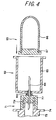
- a holder 82 of the vacuum blood collecting tube (vessel) 85 is connected with the sampling port 71 to allow an initial flow blood or an initial introduced blood (initial flow of collected blood) to be collected by the vacuum blood collecting tube 85 through the holder 82.
- the vacuum blood collecting tube 85 comprises a body 86 and a rubber plug 87 fitted on the body 86.
- the interior of the vacuum blood collecting tube 85 is vacuum or in a pressure-reduced state.
- the holder 82 comprises a cylindrical body 83 having a bottom and a double ended needle 84 provided coaxially with the body 83.
- a member (lure adapter 841) having a male screw formed thereon is fixed to the double-headed needle 84.
- a female screw engaging the male screw is formed at the center of the bottom portion of the body 83 (left end of body 83 in Fig. 4 ).
- the double-headed needle 84 is removably fixed to the body 83 by engaging the male and female screws each other.
- the length of the double-headed needle 84 at its left side in Fig. 4 is so set that it can be pierced sufficiently into the plug 77.
- the length thereof at its right side is also so set that it can be pierced sufficiently into the rubber plug 87.
- the operation of the blood collecting apparatus 1 namely, the blood collecting method that is carried out by using the blood collecting apparatus 1 will be described below.
- the blood collecting method is carried out by using a blood collecting apparatus 1 comprising a blood collecting needle 152; a blood collecting bag 10 for accommodating collected blood; a first tube 15 whose one end communicates with the blood collecting bag 10 and other end communicates with the blood collecting needle 152; a branch portion 92 provided on a portion of the first tube 15; a second tube 91 connected with the branch portion 92 at one end thereof and having a blood take-out port 71; and a flexible resin bag 20 having a third tube 31 communicating with the second tube.
- the blood collecting method comprises the step of piercing a blood collecting needle into a donor when a portion of the first tube positioned between the branch portion and the blood collecting bag is sealed; the step of removing air inside the first and second tubes by introducing an initial flow blood (initial introduced blood) from the donor into a portion of the first tube between the blood collecting needle and the branch portion and into the second tube and by accommodating air inside the portion of the first tube positioned between the blood collecting needle and the branch portion and air inside the second tube in the flexible resin bag; the step of sampling a predetermined amount of blood from the initial flow blood by using the blood take-out port; and the step of collecting a predetermined amount of blood by intercepting communication between the first tube and the flexible resin bag and by communicating the portion of the first tube between the blood collecting needle and the branch portion with a portion of the first tube between the branch portion and the blood collecting bag.
- the step of piercing the blood collecting needle 152 into a donor is performed in the condition that a portion of the first tube (first tube 15b at the side of blood collecting bag 10) positioned between the branch portion (first branch connector 92) and the blood collecting bag 10 is sealed and the first tube 15a is communicated to the flexible resin bag 20.
- the first tube 15 (first tube 15b at the side of blood collecting bag 10) is sealed with the clamp 16 to close (intercept) the duct thereof.
- the clamp 33 is opened to open the duct of the third tube 31.
- the blood collecting needle 152 is pierced into the vein (blood vessel) of the donor.
- the hub 151 is fixed with a tape.
- the breakable portion 933 of the sealing member 93 is broken to separate the solid columnar body 932 from the cylindrical body 931.
- the step of removing air from the tubes is performed. That is, an initial flow blood from the donor is introduced into the portion of the first tube (first tube 15a at the side of the blood collecting needle 152) between the blood collecting needle 152 and the branch portion (the first branch connector 92) and into the second tube 91 to accommodate the air inside the portion of the first tube (first tube 15a at the side of the blood collecting needle 152) positioned between the blood collecting needle 152 and the branch portion 92 and the air inside the second tube 91 in the flexible resin bag 20.
- the initial flow of the collected blood is introduced into the second tube 91 through the blood collecting needle 152, a part of the first tube 15 (the first tube 15a at the side of the blood collecting needle 152) and the first branch connector 92, thus flowing toward the sampling port 71.
- the duct of the first tube 15 is intercepted with the clamp 16.
- the blood flows from the first tube 15 (the first tube 15a at the side of the blood collecting needle 152) to the second tube 91 through the first branch connector 92.
- the blood is introduced into the second tube 91 by utilizing the pressure of the vein and locating the sampling port 71 and the bag 20 below the position at which the blood collecting needle 152 is pierced into the donor.
- the air inside a part of the first tube 15 (the first tube 15a at the side of the blood collecting needle 152), the air inside the second tube 91, and the air inside the first branch connector 92 flow into the third tube 31 through the second branch connector 32, thus being exhausted from one end of the third tube 31 and collected by the bag 20.
- decrease of the volume of the lumen of a part of the first tube 15 (first tube 15a at the side of the blood collecting needle 152) and the second tube 91 caused by the introduction of the blood thereinto namely, increase in the pressure of the lumen of the first tube 15 and the second tube 91 can be suppressed (restrained) by the expansion of the bag 20.
- the pressure inside the first tube 15 and the second tube 91 can be kept substantially constant, it is possible to prevent an excess load from being applied to blood cells. Thus, it is possible to prevent the blood from hemolyzing. Further, it never happens that the blood flows into the first branch connector 92 at the side of the clamp 16.
- the step of sampling blood from the initial flow blood is performed: That is, the step of sampling a predetermined amount of blood from the blood take-out port (sampling port 71) is performed.
- the step of sampling blood it may be sampled a part of the initial flow blood or blood including all of the initial flow blood.
- the third tube 31 is sealed with the clamp 33 to close (intercept) the duct thereof thereby to stop the introduction of the blood.
- the cap 76 is removed from the body 73 of the sampling port 71. Then, the double-headed needle 84 of the holder 82 is pierced into the plug 77 of the sampling port 71 and penetrated therethrough to install the holder 82 on the sampling port 71.
- the vacuum blood collecting tube 85 is inserted into the innermost portion of the holder 82 and pressed thereinto, and the double-headed needle 84 of the holder 82 is pierced through the rubber plug 87. As a result, the blood is sucked into the vacuum blood collecting tube 85 and collected thereby.
- the interior of the first tube 15 (the first tube 15a at the side of the blood collecting needle 152) and that of the second tube 91 both positioned between the blood collecting needle 152 and the sampling port 71 are mostly filled with the blood.
- the vacuum blood collecting tube 85 is extracted from the holder 82. Then, as necessary, the next vacuum blood collecting tube 85 is inserted through the holder 82 and pressed into the innermost portion of the holder 82. Then, the double-headed needle 84 of the holder 82 is pierced into the rubber plug 87 and penetrated therethrough. As a result, the blood is sucked into the vacuum blood collecting tube 85 and collected thereby. This operation is repeated to collect the initial flow blood into a necessary number of the vacuum blood collecting tubes 85.
- the holder 82 is removed from the sampling port 71, and then, the cap 76 is installed on the body 73 of the sampling port 71.
- the plug 77 Because the plug 77 is fitted on the body 73 of the sampling port 71, the plug 77 prevents leak of the blood.
- the main blood collecting step is performed. That is, a predetermined amount of blood is collected by communicating the first tube 15a with the portion of the first tube (the first tube 15b at the side of the blood collecting bag 10) positioned between the first branch portion 92 and the blood collecting bag 10.
- the blood collection is performed by using a blood collecting device of decompression type or by locating the blood collecting bag 10 at a position below the position at which the blood collecting needle 152 is pierced into the donor, namely, by utilizing the difference between the levels of the two positions.
- the clamp 16 is opened to open the duct of the first tube 15. Consequently, the blood of the donor flows through the first tube 15, thus being introduced into the blood-accommodating portion 13 of the blood collecting bag 10.
- the blood collecting needle 152 is removed from the blood vessel of the donor. Then, the cap 153 is installed on the hub 151. If necessary, the second tube 91 and the first tube 15 are fused, respectively with tube sealer or the like. Then, sealed portions of the first and second tubes 15 and 91 are cut off to remove the portion thereof located at the side of the sampling port 71. In this manner, it is possible to obtain the blood collecting bag 10 accommodating the blood not containing the initial flow blood.
- the blood accommodated in the blood collecting bag 10 is centrifuged to separate it into a plurality of blood components such as red blood cells, buffy coat, and blood plasma. Then, the obtained blood components are delivered to a predetermined blood component bag connected with the blood collecting bag 10, according to the normal procedure.
- the initial flow blood collected in the vacuum blood collecting tube 85 is discarded or can be used for biochemical examinations of blood serum and examinations of the antibody for virus (for example, AIDS, hepatitis and the like) of infectious disease.
- virus for example, AIDS, hepatitis and the like
- the blood collecting apparatus 1 it is possible to collect not containing an initial part of the initial flow blood having a probability of microbism easily and reliably.
- the blood collecting apparatus 1 prevents inclusion of bacteria into collected blood or respective components separated from the collected blood, thus having a high degree of safety.
- the blood collecting apparatus 1 does not have the second branch connector 32, the third tube 31, the clamp 33, and the bag 20, there is a possibility that some of the initial flow blood flows into the first branch connector 92 at the side of the clamp 16 and is left therein. In this case, the blood remaining there may enter into the vacuum blood collecting tube 85 when the main blood collecting is carried out.
- the main reason for the penetration of the blood into the first branch connector 92 at the side of the clamp 16 is as follows: Let it be supposed that the blood collecting apparatus 1 does not have the bag 20. In this case, in the collecting of the initial flow blood into the vacuum blood collecting tube 85 by introducing it into the second tube 91, the air inside the first tube 15a and the second tube 91 has nowhere to escape and thus cannot be exhausted to the outside. Thus, the interior of the portion of the first tube 15 and the second tube 91 located between the blood collecting needle 152 and the sampling port 71 cannot be filled with the blood, which causes the interface between the air and the blood is stopped at a portion of the first tube 15 or the second tube 91.
- the vacuum blood collecting tube 85 When the vacuum blood collecting tube 85 is installed on the holder 82 in this state, the air inside the first tube 15 and the second tube 91 is sucked into the vacuum blood collecting tube 85 immediately after the vacuum blood collecting tube 85 and the sampling port 71 communicate with each other. As a result, the duct of the first tube 15 and that of the second tube 91 become decompressed rapidly. To restore the decompressed state inside the circuit to a normal pressure, the inside of the circuit is filled with the blood. At this time, the blood also flows into the first branch connector 92 at the side of the clamp 16.
- the blood collecting apparatus 1 has the second branch connector 32, the third tube 31, the clamp 33, and the bag 20, the blood is prevented from being introduced into the first branch connector 92 at the side of the clamp 16, as described above. Thus, it is possible to eliminate the initial flow blood reliably.
- the blood introduced into the vacuum blood collecting tube 85 may be hemolyzed.
- the hemolysis may cause sodium and potassium contained in blood serum to be measured at a low accuracy.
- the cause of the occurrence of the hemolysis is as follows: As described above, let it be supposed that the blood collecting apparatus 1 does not have the bag 20. In this case, in the collecting of the initial flow blood into the vacuum blood collecting tube 85 by introducing it into the second tube 91, the interior of the portion of the first tube 15 and the second tube 91 located between the blood collecting needle 152 and the sampling port 71 cannot be filled with the blood. When the vacuum blood collecting tube 85 is installed on the holder 82 in this state, the air inside the first tube 15 and the air inside the second tube 91 are sucked into the vacuum blood collecting tube 85 immediately after the vacuum blood collecting tube 85 and the sampling port 71 communicate with each other.
- the duct of the first tube 15 and that of the second tube 91 become decompressed rapidly.
- the first tube 15 and the second tube 91 are crushed, depending on the position of the blood collecting needle 152, the degree of softness of blood vessel, and the like.
- the sectional area of the duct of the first tube 15 and that of the second tube 91 are reduced and negative pressure is comparatively large (sucking-caused moving speed of blood is comparatively large). Consequently, cells and in particular red blood cells of the collected initial flow blood are damaged.
- the blood collecting apparatus 1 has the second branch connector 32, the third tube 31, the clamp 33, and the bag 20, the blood is prevented from being hemolyzed, as described above.
- the first vacuum blood collecting tubes 85 has a smaller amount of the initial flow blood than a predetermined collectable amount (maximum amount of initial flow blood to be collected by sucking in decompressed state). The shortage of the amount of the initial flow blood affects the number of items to be examined, examination accuracy, and workability in examination adversely.
- the main reason for the shortage of the amount of the initial flow blood is as follows: Let it be supposed that the blood collecting apparatus 1 does not have the bag 20. In this case, in the collecting of the initial flow blood into the vacuum blood collecting tube 85 by introducing it into the second tube 91, the air inside the first tube 15a and the second tube 91 cannot be exhausted to the outside. Thus, the interior of the portion of the first tube 15 and the second tube 91 located between the blood collecting needle 152 and the sampling port 71 cannot be filled with the blood. When the vacuum blood collecting tube 85 is installed on the holder 82 in this state, the air inside the first tube 15 and the air inside the second tube 91 are sucked into the vacuum blood collecting tube 85 and collected thereby.
- the blood collecting apparatus 1 has the second branch connector 32, the third tube 31, the clamp 33, and the bag 20.
- the initial flow blood can be introduced into the first vacuum blood collecting tube 85, with the interior of the portion of the first tube 15 and the second tube 91 located between the blood collecting needle 152 and the sampling port 71 being filled with blood.
- the third tube 31 is sealed with the clamp 33 to intercept the duct thereof.
- the blood collecting apparatus 1 has the sealing member 93 provided on the second tune 91, it is possible to select the time at which a collected initial flow blood starts to flow toward the second tube 91.
- the collected initial flow blood can be flowed through the second tube 91 at an appropriate timing.
- the blood collecting apparatus 1 has the sealing member 93 serving as the second duct-sealing member.
- the sealing member 93 has a higher degree of operability than a clamp and a forceps.
- the blood collecting apparatus 1 has the clamp 16 serving as the first duct-sealing member.
- the clamp 16 has a higher degree of operability than other sealing members.
- the inner diameter of the second tube 91 is set comparatively small (0.5 - 2.0mm), and the thickness thereof is set comparatively large (the outer diameter thereof to 2 - 4 times as large as the inner diameter thereof) to prevent the second tube 91 from being deformed (crushed) at the time of high pressure-steam sterility.
- the blood collecting apparatus 1a of the second embodiment comprises a blood collecting needle 152 for collecting blood from a donor; a blood collecting bag 10 for accommodating collected blood; a first tube 15 (15a, 15b) whose one end communicates with the blood collecting bag 10 and other end communicates with the blood collecting needle 152; a branch portion 92 provided on a portion of the first tube 15; a second tube 91 connected with the branch portion 92 at one end thereof and having a blood take-out port at the other end thereof; and a filter 41 gas-permeable and blood-unpermeable and communicable with an interior of the second tube 91.
- Fig. 5 is a plan view showing a comparative embodiment of the blood collecting apparatus of the present invention. Description of constructions of the blood collecting apparatus of this comparative embodiment same as those of the blood collecting apparatus of the first embodiment is omitted herein. Thus, only the constructions of the blood collecting apparatus of the comparative embodiment different from those of the blood collecting apparatus of the first embodiment will be described below.
- a filter 41 is provided at one end of the third tube 31, instead of the flexible resin bag 20 of the blood collecting apparatus 1.
- the filter 41 gas-permeable and blood-unpermeable and communicable with the interior of the second tube 91 is capable of exhausting air inside the first tube 15a at the side the blood collecting needle 152 and air inside the second tube 91 when the blood collecting apparatus 1a is used.
- Other constructions of the blood collecting apparatus 1a are similar to those of the blood collecting apparatus 1.
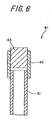
- Fig. 6 is a sectional view showing an example of the construction of the filter 41 of the blood collecting apparatus 1a.
- the filter 41 comprises a tubular body 42 and a cylindrical filter member 43 gas-permeable (ventilative) and blood-unpermeable.
- An end of the third tube 31 is liquid-tightly connected with the lower side of the tubular body 42 in Fig. 6 .
- the filter member 43 is fitted into an upper portion of the tubular body 42 in Fig. 6 .
- the tubular body 42 is made of a hard material such as polycarbonate or the like.
- the filter member 43 can be made of a sintered material containing polyethylene, polypropylene or polyamide as its main component.
- the operation (blood collecting method using the blood collecting apparatus) of the blood collecting apparatus 1a is similar to that of the blood collecting apparatus 1 except that in the blood collecting apparatus 1a, air is exhausted to the outside through the body 43 of the filter 41.
- the effect of the blood collecting apparatus 1a is also similar to that of the blood collecting apparatus 1.
- the operation of the blood collecting apparatus 1a namely, the blood collecting method to be carried out by using the blood collecting apparatus 1a will be described below.
- the second blood collecting method is carried out by using a blood collecting apparatus 1a comprising a blood collecting needle 152 for collecting blood from a donor; a blood collecting bag 10 for accommodating collected blood; a first tube 15 whose one end communicates with the blood collecting bag 10 and other end communicates with the blood collecting needle 152; a branch portion 92 provided on a portion of the first tube 15; a second tube 91 connected with the branch portion 92 at one end thereof and having a blood take-out port 71; and a filter 41 gas-permeable and blood-unpermeable and communicable with an interior of the second tube.
- a blood collecting apparatus 1a comprising a blood collecting needle 152 for collecting blood from a donor; a blood collecting bag 10 for accommodating collected blood; a first tube 15 whose one end communicates with the blood collecting bag 10 and other end communicates with the blood collecting needle 152; a branch portion 92 provided on a portion of the first tube 15; a second tube 91 connected with the branch portion 92 at one end thereof and having
- the second blood collecting method comprises the steps of piercing a blood collecting needle into a donor when a portion of the first tube positioned between the branch portion and the blood collecting bag is sealed; exhausting air inside the first and second tubes from the filter by introducing an initial flow blood from the donor into a portion of the first tube between the blood collecting needle and the branch portion and into the second; sampling blood from the initial flow blood by using the blood take-out port; and collecting a predetermined amount of blood by intercepting communication between the first tube and the filter and by communicating the portion of the first tube between the blood collecting needle and the branch portion with a portion of the first tube between the branch portion and the blood collecting bag.
- the blood collecting needle-piercing step of the second embodiment is the same as that of the first embodiment. More specifically, as shown in Fig. 5 , the first tube 15 (the first tube 15b at the side of the blood collecting bag 10) is sealed with the clamp 16 to close (intercept) the duct thereof. The clamp 33 is opened to open the duct of the third tube 31.
- the blood collecting needle 152 is pierced into the vein (blood vessel) of a donor.
- the hub 151 is fixed with a tape.
- the breakable portion 933 of the sealing member 93 is broken to separate the solid columnar body 932 from the cylindrical body 931.
- the step of removing the air from the tubes is performed. That is, the blood (initial flow blood) of the donor is introduced into the portion of the first tube 15a and into the second tube 91 to exhaust air inside the first tube 15a and air inside the second tube 91 from the filter 41.
- the blood of the donor is introduced into the first tube (the first tube 15a at the side of the blood collecting needle) between the blood collecting needle 152 and the branch portion (first branch connector 92) and into the second tube 91 to exhaust the air inside the first tube (the first tube 15a at the side of the blood collecting needle 152) positioned between the blood collecting needle 152 and the branch portion 92 and the air inside the second tube 91 to the outside from the filter 41.
- the initial flow blood is introduced into the second tube 91 through the blood collecting needle 152, a part of the first tube 15 (the first tube 15a at the side of the blood collecting needle 152) and the first branch connector 92, thus flowing toward the sampling port 71.
- the duct of the first tube 15 is intercepted with the clamp 16.
- the blood flows from the first tube 15 (the first tube 15a at the side of the blood collecting needle 152) to the second tube 91 through the first branch connector 92.
- the blood is introduced into the second tube 91 by utilizing the pressure of the vein and locating the sampling port 71 below the position at which the blood collecting needle 152 is pierced into the donor.
- the air inside a part of the first tube 15 (the first tube 15a at the side of the blood collecting needle), the second tube 91, and the first branch connector 92 flow into the third tube 31 through the second branch connector 32, thus being exhausted from the filter 41 positioned at the termination of the third tube. That is, because the air inside a part of the first tube 15 (the first tube 15a at the side of the blood collecting needle) and the air inside the second tube 91 are exhausted by the introduction of the blood thereinto, the pressure of the lumen of the first tube 15 and the second tube 91 do not increase.
- the pressure inside the first tube 15 and the second tube 91 can be kept substantially constant, it is possible to prevent an excess load from being applied to blood cells. Thus, it is possible to prevent the blood from hemolyzing. Further, it does not happen that the blood flows into the first branch connector 92 at the side of the clamp 16.
- step of sampling blood from the initial flow blood is performed. That is, the step of collecting a predetermined amount of blood from the blood take-out port (sampling port 71) is performed. In the step of sampling blood, it may be sampled a part of the initial flow blood or blood including all of the initial flow blood.
- the third tube 31 is sealed with the clamp 33 to close (intercept) the duct thereof thereby to stop the introduction of the blood.
- the cap 76 is removed from the body 73 of the sampling port 71. Then, the double-headed needle 84 of the holder 82 is pierced into the plug 77 of the sampling port 71 and penetrated therethrough to install the holder 82 on the sampling port 71.
- the vacuum blood collecting tube 85 is inserted into the innermost portion of the holder 82 and pressed thereinto, and the double-headed needle 84 of the holder 82 is pierced through the rubber plug 87. As a result, the blood is sucked into the vacuum blood collecting tube 85 and collected thereby.
- the interior of the first tube 15 (the first tube 15a at the side of the blood collecting needle 152) and that of the second tube 91 both positioned between the blood collecting needle 152 and the sampling port 71 are mostly filled with the blood.
- the vacuum blood collecting tube 85 is extracted from the holder 82. Then, as necessary, the next vacuum blood collecting tube 85 is inserted through the holder 82 and pressed into the innermost portion of the holder 82. Then, the double-headed needle 84 of the holder 82 is pierced into the rubber plug 87 and penetrated therethrough. As a result, the blood is sucked into the vacuum blood collecting tube 85 and collected thereby. This operation is repeated to collect the initial flow blood is introduced into a necessary number of the vacuum blood collecting tubes 85.
- the holder 82 is removed from the sampling port 71, and then, the cap 76 is installed on the body 73 of the sampling port 71.
- the plug 77 Because the plug 77 is fitted on the body 73 of the sampling port 71, the plug 77 prevents leak of the blood.
- the communication between the first tube 15 and the blood flexible resin bag 20 is intercepted and the blood collecting step is performed. That is, a predetermined amount of blood is collected by communicating the first tube 15a with the portion of the first tube (the first tube 15b at the side of the blood collecting bag 10) positioned between the branch portion and the blood collecting bag 10.
- a main blood collecting into the blood collecting bag 10 is started.
- the blood collecting is performed by using a blood collecting device of decompression type or by locating the blood collecting bag 10 at a position below the position at which the blood collecting needle 152 is pierced into the donor, namely, by utilizing the difference between the levels of the two positions.
- the clamp 16 is opened to open the duct of the first tube 15. Consequently, the blood of the donor flows through the first tube 15, thus being introduced into the blood-accommodating portion 13 of the blood collecting bag 10.
- the blood collecting needle 152 is removed from the blood vessel of the donor. Then, the cap 153 is installed on the hub 151. If necessary, the second tube 91 and the first tube 15 are fused, respectively with tube sealer or the like. Then, sealed portions of the first and second tubes 15 and 91 are cut off to remove the portion thereof located at the side of the sampling port 71. In this manner, it is possible to obtain the blood collecting bag 10 accommodating the blood not containing the initial flow blood.
- the third embodiment of the blood collecting apparatus of the present invention will be described below.
- Fig. 7 is a plan view showing another comparative embodiment of the blood collecting apparatus of the present invention. Description of constructions of the blood collecting apparatus of this comparative embodiment same as those of the blood collecting apparatus of the first embodiment is omitted herein. Thus, only the constructions of the blood collecting apparatus of the comparative embodiment different from those of the blood collecting apparatus of the first embodiment will be described below.
- the blood collecting apparatus 1b has a filter provided on the branch connector 32 and a sealable air vent 51 provided thereon.
- the blood collecting apparatus 1b does not have the third tube 31, the clamp 33, and the flexible resin bag 20 unlike the blood collecting apparatus 1 of the first embodiment.
- the other constructions of the blood collecting apparatus 1b of the comparative embodiment are similar to those of the blood collecting apparatus 1 of the first embodiment.
- Fig. 8 is a sectional view showing an example of the sealable air vent 51 for use in the blood collecting apparatus 1b of the present invention.
- the air vent (filter) 51 comprises a vent adapter 52, an adapter cap 53, a vent filter (filter body) 54 gas-permeable (ventilative) and blood-unpermeable, and a vent cap 55.
- the vent adapter 52 is cylindrical and has a projection 521 formed on a rotational shaft of the cylinder. The projection 521 is pressed into the second branch connector 32.
- the disk-shaped vent filter 54 is provided on the upper surface of the vent adapter 52 at the side (upper side in Fig. 8 ) not provided with the projection 521 such that the vent filter 54 seals the vent adapter 52.
- the adapter cap 53 is installed on the periphery of the vent filter 54.
- the adapter cap 53 is disk-shaped and has an air-permeable hole 531 at its center to allow air to pass between the inner space of the second branch connector 32 and the outside through the vent filter 54.
- a projection 551 which engages the hole 531 when the vent cap 55 is installed on the vent adapter 52 is formed at the center of the vent cap 55.
- a third duct duct communicating with the inside of the second tube and the outside through the air vent 51
- the third duct is constituted of a hollow portion (duct) between the branch point of the second branch connector 32 and a position immediately prior to the vent cap 55 of the air vent 51.
- the vent cap 55 constitutes a third duct-sealing member.
- the air vent (filter) 51 constitutes a main portion of the pressure buffering means.
- vent filter 54 it is possible to used various kinds of membrane filters such as a membrane filter consisting of a polyester resin coated with polyvinyl chloride, a membrane filter consisting of polytetrafluoroethylene laminated on or coating nonwoven cloth of polyethylene, a membrane filter consisting an acetate film coated with silicone resin, and the like.
- membrane filters such as a membrane filter consisting of a polyester resin coated with polyvinyl chloride, a membrane filter consisting of polytetrafluoroethylene laminated on or coating nonwoven cloth of polyethylene, a membrane filter consisting an acetate film coated with silicone resin, and the like.
- the operation (blood collecting method using the blood collecting apparatus) of the blood collecting apparatus 1b is similar to that of the blood collecting apparatus 1a except that in the blood collecting apparatus 1b, the vent cap 55 of the air vent (filter) 51 is opened and closed in the blood collecting apparatus 1b whereas in the blood collecting apparatus 1a, the clamp 33 of the blood collecting apparatus 1a is opened and closed and that in the blood collecting apparatus 1b, air is exhausted to the outside through the vent filter 54 of the air vent.
- the effect of the blood collecting apparatus 1b is also similar to that of the blood collecting apparatus 1.
- the blood collecting apparatus of the present invention and the blood collecting methods thereof using each blood collecting apparatus have been described with reference to the drawings.
- the present invention is not limited to the first embodiment, but the construction of each part of the blood collecting apparatus of each embodiment can be replaced with a part having a desired construction provided that it has the same function as that of each part of the blood collecting apparatus of each embodiment.
- the second duct may be provided with a check valve 94 (reverse flow prevention member).
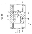
- Fig. 10 is a vertical sectional view showing an example of the construction of the 94.
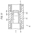
- Fig. 11 is a sectional view taken along a line A-A of Fig. 10 .
- the right side in Figs. 10 and 11 is referred to as “front side” and the left side therein is referred to as "rear side”.
- the check valve 94 comprises a short tube 940 composed of a flexible resin such as soft polyvinyl chloride and a body 941 made of an elastic material.
- the body 941 is liquid-tightly inserted into the short tube 940 and fixed thereto.
- the front end of the short tune 940 is liquid-tightly connected with the sampling port 71.
- the rear end of the short tube 940 is liquid-tightly connected with the second branch connector 32.
- the body 941 has a hollow portion 942 communicating with the second branch connector 32 and forming a part of the blood duct of the check valve 94.
- a tapered surface 943 is formed on the front end of the hollow portion 942. That is, the vertical length (L) of the front side of the hollow portion 942 decreases gradually from the rear side toward the front side.
- a pair of plate-shaped opening/closing members 944 and 944 is formed at the front end of the body 941.
- the opening/closing members 944 and 944 are in close contact with each other owing to their elastic and restoring forces, thus closing the duct of the check valve 94.
- the pressure of the blood is applied to the peripheral surface of the opening/closing members 944 and 944, thus acting to bring them into contact each other closely.
- the blood does not flow from the front side to the rear side.
- rubber materials such as natural rubber, isoprene rubber, butyl rubber, silicone rubber, urethane rubber, acrylic rubber, and butadiene rubber, styrene-butadiene rubber can be preferably used.
- the check valve 94 prevents a reverse flow blood. That is, the blood does not flow from the sampling port 71 toward the first branch connector 92, but from the first branch connector 92 toward the sampling port 71.
- the position of the check valve 94 is not limited to a specified position as long as it is positioned on the second duct. As described above, it is favorable that the check valve 94 is positioned at the side of the sampling port 71 with respect to the second branch connector 32. It is more favorable that the check valve 94 is positioned between the second branch connector 32 and the sampling port 71.
- the check valve 94 When the check valve 94 is installed at the above-described position, the check valve 94 does not constitute a pressure drag when blood is flowed to a position proximate to the second branch connector 32. Thus, the check valve 94 allows the introduction of the blood to the bag 20 to be accomplished smoothly.
- the first duct-sealing member may be composed of a sealing member 95 which can be broken to open the first duct. That is, the clamp 16 shown in Figs. 1 , 5 , and 7 may be replaced with the sealing member 95.
- the sealing member 95 of the blood collecting apparatus 1c, 1d, and 1e a member similar to the above-described sealing member 93 can be used.
- the second tube 91 may be closed with a tube-closing member such as a clamp to intercept the duct (second duct).
- a tube-closing member such as a clamp to intercept the duct (second duct).
- the tube-closing member is positioned between the first branch connector 92 and the sealing member 93.
- the second tube 91 is not provided with the sealing member 93 when the second tube 91 is provided with the tube-closing member.
- the sampling port 71 and the third tube 31 may be connected to the end of each branch of the second branch connector 32 reversely. That is, the third tube 31 may be connected with the end of the upper branch of the second branch connector 32 in Figs. 1 and 5 and the sampling port 71 may be connected with the end of the lower branch thereof in Figs. 1 and 5 .
- the air vent 51 may be connected with the end of the upper branch of the second branch connector 32 in Fig. 7 and the sampling port 71 may be connected with the end of the lower branch thereof in Fig. 7 .
- the branch portions may be composed of a multi-plug such as a three-way plug instead of the branch connectors as shown in the drawings.
- air inside the first tube 15 (first tube 15a at the side of the blood collecting needle 152) between the branch portion 92 and the blood collecting needle 152 and air inside the second tube 91 can be accommodated in the flexible resin or exhausted to the outside.
- an initial flow blood is prevented from being left in the branch portion between the first tube and the second tube at the side of the blood collecting bag. That is, it is possible to collect blood not containing a initial part of the initial flow blood having a probability of microbism easily and reliably from blood collected from a donor.
- the blood collecting apparatus of the present invention has pressure buffering means for restraining fluctuation of the pressure in the second duct, the initial flow blood is prevented from being left in the branch portion between the first tube and the second tube at the side of the blood collecting bag. That is, it is possible to remove the initial flow blood having a probability of microbism easily and reliably from blood collected from a donor. Therefore, it is possible to prevent inclusion of bacteria into the collected blood or respective components separated from the collected blood, thus having a high degree of safety.
- the pressure buffering means prevents (prevents cells in blood from being damaged, for example, hemolysis) an excess load from being applied to the blood, thus allowing the initial flow blood to be collected in a preferable state and preventing a collecting amount of the initial flow blood from being reduced.
- the blood collecting apparatus 1 shown in Fig. 1 was prepared. Two soft polyvinyl sheets were used as the material of the flexible resin bag 20. They were laminated on each other and the peripheral edges thereof were fused to each other. The bag 20 had a capacity of 20ml.
- air inside the first tube 15a positioned at the side of the blood collecting needle and air inside the second tube 91 were introduced into the bag 20 by introducing an initial flow blood. Then, an initial part of the initial flow blood was collected in the vacuum blood collecting tube 85. Then, 200ml of blood was collected in the blood collecting bags 10.
- the blood sampling capacity of each vacuum blood collecting tube 85 was 10ml.
- the blood collecting apparatus 1a shown in Fig. 5 was prepared.
- the body 43 of the filter 41 provided on the third tube 31 was made of a sintered material containing polypropylene as its main component.
- air inside the first tube 15a positioned at the side of the blood collecting needle and air inside the second tube 91 were discharged from the filter by introducing an initial flow blood.
- a initial part of the initial flow blood was collected in the vacuum blood collecting tube 85.
- 200ml of blood was collected by the blood collecting bag 10.
- the blood sampling capacity of each vacuum blood collecting tube 85 was 10ml.
- the blood collecting apparatus 1b shown in Fig. 7 was prepared.
- a membrane filter made of polytetrafluoroethylene was used as the vent filter 54 of the air vent (filter) 51 provided at the second branch portion 32.
- air inside the first tube 15a positioned at the side of the blood collecting needle and air inside the second tube 91 were discharged through the vent filter 54 by introducing an initial flow blood.
- a initial part of the initial flow blood was collected in the vacuum blood collecting tube 85.
- 200ml of blood was collected by the blood collecting bag 10.
- the blood sampling capacity of each vacuum blood collecting tube 85 was 10ml.
- the blood collecting apparatus had a construction similar to that of the embodiment 1.
- an initial part of an initial flow blood was collected in the vacuum blood collecting tube 85.
- 200ml of blood was collected by the blood collecting bag 10.
- the blood sampling capacity of each vacuum blood collecting tube 85 was 10ml.
- the blood collecting apparatus had a construction similar to that of the embodiment 1. Using the blood collecting apparatus and a conventional method, 200ml of blood was collected by the blood collecting bag 10.
- a bacterium fluid of Yersinia enterocolitica (buffer and suspension of phosphoric acid, concentration: 100cfu/ml) was applied to a donor at a predetermined piercing portion thereof with swabs once a day for a week before blood was collected from them. The piercing portions of the donors were not washed for a week before blood was collected therefrom.
- the tube in the range from the blood collecting needle to the sampling port was substantially filled with blood. Because the initial flow blood was collected into each vacuum blood collecting tube installed on the holder, it did not occur that the blood flowed to the first branch connector 92 at the side of the clamp 16. Thus, blood collected from the donor did not contain the initial flow blood. Therefore, as indicated in table 1, the number of bacterium-detected bloods was zero.
- Table 2 indicates the degree of hemolysis (number of detected hemolysis) of each collected blood introduced into each vacuum blood collecting tube 85 and average values of the amounts of the initial flow blood introduced into the vacuum blood collecting tubes 85.
- the degree of hemolysis of the initial flow of each collected blood was examined as follows: After blood coagulated, blood serum was centrifuged at 3000rpm for 10 minutes to visually observe the tone of each blood serum. According to the tone of red, the degree of hemolysis of the initial flow of each collected blood was determined by using the following three levels, namely, not hemolyzed (level 0), slightly hemolyzed (level 1), and hemolyzed (level 2).
- the tube in the range from the blood collecting needle to the sampling port was substantially filled with blood. Because the initial flow blood was collected into each vacuum blood collecting tube installed on the holder, an excess load was not applied to blood. Thus, the blood did not hemolyze as indicated in table 2 below. That is, in the first - third embodiments, slight degree of hemolysis (level 1) and hemolysis (level 2) were not observed.
- each vacuum blood collecting tube in the introduction of the initial flow blood into each vacuum blood collecting tube, each vacuum blood collecting tube was installed on the holder, with the tube in the range from the blood collecting needle to the sampling port being substantially filled with blood. Thus, as indicated in table 2 below, the amount of the initial flow blood was not reduced.
- the initial flow blood was introduced into the vacuum blood collecting tube, without the inside of the tube in the range from the blood collecting needle to the sampling port being filled with blood.
- air inside the tube was sucked into the vacuum blood collecting tube and collected therein. Consequently, the amount of the initial flow of collected blood was reduced by 3.5ml corresponding to the spatial volume of the length (35cm) of the tube.
Landscapes
- Health & Medical Sciences (AREA)
- Heart & Thoracic Surgery (AREA)
- Vascular Medicine (AREA)
- Engineering & Computer Science (AREA)
- Anesthesiology (AREA)
- Biomedical Technology (AREA)
- Hematology (AREA)
- Life Sciences & Earth Sciences (AREA)
- Animal Behavior & Ethology (AREA)
- General Health & Medical Sciences (AREA)
- Public Health (AREA)
- Veterinary Medicine (AREA)
- External Artificial Organs (AREA)
- Investigating Or Analysing Biological Materials (AREA)
Claims (9)
- Blutsammelvorrichtung (1, 1c, 1f), umfassend:eine Blutabnahmenadel (152) zum Abnehmen von Blut von einem Spender;eine Blutsammeltasche (10) zum Aufnehmen von abgenommenem Blut;einen ersten Schlauch (15), dessen eines Ende mit der Blutsammeltasche (10) verbunden ist und dessen anderes Ende mit der Blutabnahmenadel (152) verbunden ist;einen ersten Verzweigungsabschnitt (92), welcher an einem Abschnitt des ersten Schlauchs (15) vorgesehen ist;ein erstes Kanalverschlußelement (16), welches zwischen dem ersten Verzweigungsabschnitt (92) und der Blutsammeltasche (10) angeordnet ist und in der Lage ist, einen ersten Kanal in dem ersten Schlauch (15) zu unterbrechen;einen zweiten Schlauch (91), welcher an einem Ende davon mit dem ersten Verzweigungsabschnitt (92) verbunden ist und eine Blutentnahmeöffnung (71) aufweist;einen Beutel aus flexiblem Harz (20), welcher einen Aufnahmeabschnitt (23) zum Aufnehmen von abgenommenem Blut und einen dritten Schlauch (31), welcher mit dem ersten Verzweigungsabschnitt (92) verbunden ist, aufweist;dadurch gekennzeichnet, daßdas erste Kanalverschlußelement (16) eine Klemme (16) ist;der zweite Schlauch (91) einen zweiten Verzweigungsabschnitt (32) aufweist, welcher zwischen dem ersten Verzweigungsabschnitt (92) und der Blutentnahmeöffnung (71) angeordnet ist;wobei der dritte Schlauch (31) an einem Ende davon mit dem zweiten Verzweigungsabschnitt (32) verbunden ist und an dem anderen Ende davon mit dem Beutel aus flexiblem Harz (20) verbunden ist;der Beutel aus flexiblem Harz (20) in der Lage ist, Luft in einem Abschnitt des ersten Schlauchs (15) zwischen dem Verzweigungsabschnitt (92) und der Blutabnahmenadel (152) und Luft in dem zweiten Schlauch (91) aufzunehmen, wenn die Blutsammelvorrichtung verwendet wird;wobei der zweite Verzweigungsabschnitt (32), der dritte Schlauch (31), ein zweites Kanalverschlußelement (93, 33), welches an dem zweiten Schlauch (91) oder an dem dritten Schlauch (31) vorgesehen ist, und der Beutel aus flexiblem Harz (20) eine Druckpuffereinrichtung zum Verhindern einer Schwankung des Drucks in dem zweiten Schlauch (91) bilden.
- Blutsammelvorrichtung nach Anspruch 1, wobei sich das Fassungsvermögen des Beutels aus flexiblem Harz (20) in dem Bereich von 1 - 100 ml befindet.
- Blutsammelvorrichtung nach Anspruch 1 oder 2, ferner umfassend das zweite Kanalverschlußelement (93), welches in der Lage ist, einen Kanal in dem zweiten Schlauch (91) zu unterbrechen.
- Blutsammelvorrichtung nach Anspruch 3, wobei das Kanalverschlußelement (93) aus einem zerbrechlichen Verschlußelement, welches den Kanal des ersten und des zweiten Schlauchs jeweils öffnet, wenn das zerbrechliche Verschlußelement zerbrochen wird, oder einem Klemmelement, welches geöffnet und geschlossen werden kann, besteht.
- Blutsammelvorrichtung nach einem der Ansprüche 1 bis 4, wobei das zweite Kanalverschlußelement (33) in der Lage ist, einen Kanal in dem dritten Schlauch (31) zu unterbrechen.
- Blutsammelvorrichtung nach Anspruch 5, wobei das zweite Kanalverschlußelement (33), welches in der Lage ist, den Kanal in dem dritten Schlauch (31) zu unterbrechen, aus einem Klemmelement besteht, welches geöffnet und geschlossen werden kann.
- Blutsammelvorrichtung nach einem der Ansprüche 1 bis 6, ferner umfassend ein Rückflußverhinderungselement (94), welches einen Durchfluß von dem ersten Verzweigungsabschnitt (92), welcher an dem ersten Schlauch (15) vorgesehen ist, zu dem Blutentnahmeabschnitt (71) ermöglicht und einen Durchfluß in entgegengesetzter Richtung zu dem Durchfluß von dem Verzweigungsabschnitt (92) zu der Blutentnahmeöffnung (71) verhindert.
- Blutsammelvorrichtung nach einem der Ansprüche 1 bis 7, wobei eine Flächengröße einer Schnittfläche eines Kanals in dem zweiten Schlauch (91) kleiner als eine Flächengröße einer Schnittfläche des Kanals in dem ersten Schlauch (15) ist.
- Blutsammelvorrichtung nach einem der Ansprüche 1 bis 8, wobei eine Nadel (84) eines Blutabnahmewerkzeugs (82) für ein Unterdruck-Blutsammelrohr (85) in die Blutentnahmeöffnung (71) eingestochen sein kann.
Applications Claiming Priority (3)
| Application Number | Priority Date | Filing Date | Title |
|---|---|---|---|
| JP02039498A JP3776227B2 (ja) | 1998-01-16 | 1998-01-16 | 採血用器具 |
| JP2039498 | 1998-01-16 | ||
| EP99100398A EP0930079B1 (de) | 1998-01-16 | 1999-01-18 | Blutsammlungsgerät |
Related Parent Applications (1)
| Application Number | Title | Priority Date | Filing Date |
|---|---|---|---|
| EP99100398A Division EP0930079B1 (de) | 1998-01-16 | 1999-01-18 | Blutsammlungsgerät |
Publications (2)
| Publication Number | Publication Date |
|---|---|
| EP1602385A1 EP1602385A1 (de) | 2005-12-07 |
| EP1602385B1 true EP1602385B1 (de) | 2008-12-24 |
Family
ID=12025811
Family Applications (2)
| Application Number | Title | Priority Date | Filing Date |
|---|---|---|---|
| EP99100398A Expired - Lifetime EP0930079B1 (de) | 1998-01-16 | 1999-01-18 | Blutsammlungsgerät |
| EP05017226A Expired - Lifetime EP1602385B1 (de) | 1998-01-16 | 1999-01-18 | Blutsammlungsgerät |
Family Applications Before (1)
| Application Number | Title | Priority Date | Filing Date |
|---|---|---|---|
| EP99100398A Expired - Lifetime EP0930079B1 (de) | 1998-01-16 | 1999-01-18 | Blutsammlungsgerät |
Country Status (5)
| Country | Link |
|---|---|
| US (2) | US6328726B1 (de) |
| EP (2) | EP0930079B1 (de) |
| JP (1) | JP3776227B2 (de) |
| CA (1) | CA2258894C (de) |
| DE (2) | DE69940174D1 (de) |
Families Citing this family (69)
| Publication number | Priority date | Publication date | Assignee | Title |
|---|---|---|---|---|
| US6592613B1 (en) * | 1998-01-16 | 2003-07-15 | Terumo Kabushiki Kaisha | Blood collecting apparatus and blood collecting method using blood collecting apparatus |
| WO2000007642A1 (en) * | 1998-08-07 | 2000-02-17 | Pall Corporation | Biological fluid processing system |
| FR2795647B1 (fr) * | 1999-06-30 | 2004-05-07 | Maco Pharma Sa | Ensemble de poches destine a recevoir un fluide biologique et a mettre en evidence une eventuelle contamination du fluide biologique |
| US7824343B2 (en) | 1999-07-29 | 2010-11-02 | Fenwal, Inc. | Method and apparatus for blood sampling |
| US20030176813A1 (en) * | 1999-07-29 | 2003-09-18 | Jean-Marie Mathias | Biological fluid sampling apparatus |
| US7479131B2 (en) * | 1999-07-29 | 2009-01-20 | Fenwal, Inc. | Biological fluid sampling apparatus, assembly and method |
| US6387086B2 (en) * | 1999-07-29 | 2002-05-14 | Baxter International Inc. | Blood processing set including an integrated blood sampling system |
| AU6498600A (en) | 1999-07-29 | 2001-02-19 | Baxter International Inc. | Sampling tube holder for blood sampling system |
| US6730071B1 (en) * | 2000-09-25 | 2004-05-04 | Alyssa J. Dassa | Collection, storage, transportation and sampling system and method of use thereof |
| US7727219B2 (en) * | 2001-10-22 | 2010-06-01 | Vita 34 Ag | Sterile system and methods for collecting, transporting, storing and cyropreserving body fluids |
| DE10151343A1 (de) * | 2001-10-22 | 2003-05-08 | Vita 34 Ag | Beutelsystem für die Kryokonservierung von Körperflüssigkeiten |
| ATE480293T1 (de) * | 2002-01-31 | 2010-09-15 | Fenwal Inc | Irreversibel schliessbare stromregelklemme |
| US8262639B2 (en) * | 2002-01-31 | 2012-09-11 | Fenwal, Inc. | Irreversible flow control clamp |
| EP1476208B1 (de) * | 2002-02-01 | 2011-10-05 | CaridianBCT, Inc. | System zur entnahme und aufbereitung von vollblut |
| US7168459B2 (en) * | 2002-04-12 | 2007-01-30 | Hynetics Llc | Feed bags and methods of use |
| AU2003234382B2 (en) * | 2002-05-13 | 2010-07-08 | Becton, Dickinson And Company | Protease inhibitor sample collection system |
| US7384416B2 (en) * | 2002-08-12 | 2008-06-10 | Macopharma | Device and method for irreversible closure of fluid communication in a container system |
| WO2004058067A1 (en) * | 2002-12-18 | 2004-07-15 | Lydall, Inc. | Closed system blood sampling device |
| US20040127816A1 (en) * | 2002-12-30 | 2004-07-01 | Adriano Braun Galvao | Handheld blood collection device |
| US9247902B2 (en) * | 2003-11-19 | 2016-02-02 | Noble House Group Pty Ltd. | Sterile sampling methods and apparatus |
| US20050124965A1 (en) * | 2003-12-08 | 2005-06-09 | Becton, Dickinson And Company | Phosphatase inhibitor sample collection system |
| US20060036231A1 (en) * | 2004-05-27 | 2006-02-16 | Conard William A | Injection port and method of making the same |
| JP3813974B2 (ja) * | 2005-05-26 | 2006-08-23 | テルモ株式会社 | 採血用器具 |
| JP4861649B2 (ja) * | 2005-07-08 | 2012-01-25 | テルモ株式会社 | 血液成分採取回路および血液成分採取装置 |
| CA2656139C (en) * | 2006-06-20 | 2012-06-05 | Erik John Woods | Systems and methods for cryopreservation of cells |
| JP4839198B2 (ja) * | 2006-12-13 | 2011-12-21 | テルモ株式会社 | 検査用血液容器および採血器具 |
| US8197420B2 (en) | 2006-12-18 | 2012-06-12 | Magnolia Medical Technologies, Inc. | Systems and methods for parenterally procuring bodily-fluid samples with reduced contamination |
| JP5133577B2 (ja) * | 2007-02-26 | 2013-01-30 | 川澄化学工業株式会社 | 採血器具及び流路開閉手段 |
| JP2009089919A (ja) * | 2007-10-10 | 2009-04-30 | Kawasumi Lab Inc | 採血器具 |
| CA2749771C (en) * | 2008-01-28 | 2018-05-01 | Milux Holding S.A. | A drainage device comprising an active filter |
| PL2475973T3 (pl) | 2009-09-11 | 2018-09-28 | Keofitt A/S | Urządzenie próbkujące |
| US20110201908A1 (en) * | 2010-02-17 | 2011-08-18 | Farkas Joshua D | Intermittent extracorporeal spectrophotometry |
| US8864684B2 (en) | 2011-10-13 | 2014-10-21 | Magnolia Medical Technologies, Inc. | Fluid diversion mechanism for bodily-fluid sampling |
| US8535241B2 (en) | 2011-10-13 | 2013-09-17 | Magnolia Medical Technologies, Inc. | Fluid diversion mechanism for bodily-fluid sampling |
| WO2013136888A1 (ja) | 2012-03-12 | 2013-09-19 | テルモ株式会社 | 血液流路切換装置及び血液バッグシステム |
| CN104168928A (zh) * | 2012-03-12 | 2014-11-26 | 泰尔茂株式会社 | 血液流路连接装置及血液袋系统 |
| WO2013137361A1 (ja) * | 2012-03-14 | 2013-09-19 | テルモ株式会社 | 検査用血液容器および採血器具 |
| JP5997760B2 (ja) * | 2012-03-14 | 2016-09-28 | テルモ株式会社 | 検査用血液容器および採血器具 |
| WO2013137360A1 (ja) * | 2012-03-14 | 2013-09-19 | テルモ株式会社 | 検査用血液容器および採血器具 |
| US9022951B2 (en) | 2012-05-30 | 2015-05-05 | Magnolia Medical Technologies, Inc. | Fluid diversion mechanism for bodily-fluid sampling |
| US9060724B2 (en) | 2012-05-30 | 2015-06-23 | Magnolia Medical Technologies, Inc. | Fluid diversion mechanism for bodily-fluid sampling |
| WO2014022275A1 (en) | 2012-08-01 | 2014-02-06 | Magnolia Medical Technologies, Inc. | Fluid diversion mechanism for bodily-fluid sampling |
| US9833606B2 (en) | 2012-09-07 | 2017-12-05 | Fenwal, Inc. | Non-reopenable flow control clamp |
| EP3906952A1 (de) | 2012-10-11 | 2021-11-10 | Magnolia Medical Technologies, Inc. | Systeme und verfahren zur abgabe einer flüssigkeit an einen patienten mit reduzierter kontamination |
| CA2931983C (en) | 2012-11-30 | 2021-12-07 | Magnolia Medical Technologies, Inc. | Syringe based fluid diversion mechanism for bodily-fluid sampling |
| US10772548B2 (en) | 2012-12-04 | 2020-09-15 | Magnolia Medical Technologies, Inc. | Sterile bodily-fluid collection device and methods |
| IL303591B2 (en) | 2012-12-04 | 2025-11-01 | Magnolia Medical Technologies Inc | Sterile bodily-fluid collection device and methods |
| US20140276578A1 (en) | 2013-03-12 | 2014-09-18 | Magnolia Medical Technologies, Inc. | Methods and apparatus for selectively occluding the lumen of a needle |
| JP2015159856A (ja) * | 2014-02-26 | 2015-09-07 | テルモ株式会社 | 血液バッグシステム |
| EP4218708B1 (de) | 2014-03-03 | 2024-12-18 | Magnolia Medical Technologies, Inc. | Vorrichtung zur desinfektion eines probenbehälters |
| US9782707B2 (en) | 2014-03-24 | 2017-10-10 | Fenwal, Inc. | Biological fluid filters having flexible walls and methods for making such filters |
| US9968738B2 (en) | 2014-03-24 | 2018-05-15 | Fenwal, Inc. | Biological fluid filters with molded frame and methods for making such filters |
| US9796166B2 (en) | 2014-03-24 | 2017-10-24 | Fenwal, Inc. | Flexible biological fluid filters |
| US10376627B2 (en) | 2014-03-24 | 2019-08-13 | Fenwal, Inc. | Flexible biological fluid filters |
| US10159778B2 (en) | 2014-03-24 | 2018-12-25 | Fenwal, Inc. | Biological fluid filters having flexible walls and methods for making such filters |
| EP3769681B1 (de) | 2015-06-12 | 2022-03-02 | Magnolia Medical Technologies, Inc. | Vorrichtung zur probenahme und fluidtransfer von körperflüssigkeiten |
| EP3344213B1 (de) | 2015-09-03 | 2020-04-22 | Magnolia Medical Technologies, Inc. | System zum aufrechterhalten der sterilität eines probenbehälters |
| US11135349B2 (en) | 2016-06-16 | 2021-10-05 | Haemonetics Corporation | Y-connector for blood processing system and disposable set containing same |
| JP6564801B2 (ja) * | 2017-03-22 | 2019-08-21 | 日機装株式会社 | 医療用接続具 |
| US20180353117A1 (en) | 2017-06-09 | 2018-12-13 | Magnolia Medical Technologies, Inc. | Fluid control devices and methods of using the same |
| CN116250868A (zh) | 2017-09-12 | 2023-06-13 | 木兰医药技术股份有限公司 | 流体控制装置及其使用方法 |
| CN115553822A (zh) | 2017-12-07 | 2023-01-03 | 木兰医药技术股份有限公司 | 流体控制装置及其使用方法 |
| US11786155B2 (en) | 2019-02-08 | 2023-10-17 | Magnolia Medical Technologies, Inc. | Devices and methods for bodily fluid collection and distribution |
| CN113784793B (zh) | 2019-03-11 | 2023-09-19 | 木兰医药技术股份有限公司 | 流体控制装置及其使用方法 |
| JP6848108B1 (ja) * | 2020-06-30 | 2021-03-24 | テルモ株式会社 | 医療用バッグシステム及び遠心分離システム |
| CN113499498A (zh) * | 2021-07-08 | 2021-10-15 | 南华大学附属第一医院 | 一种关节腔自循环冲吸泵 |
| JP7763061B2 (ja) * | 2021-09-27 | 2025-10-31 | テルモ株式会社 | 採取キット及び採取方法 |
| WO2023076544A1 (en) * | 2021-10-29 | 2023-05-04 | Global Life Sciences Solutions Usa Llc | Female bonding port for tubing joints and sterile vent filter having a female bonding port |
| CN114504012B (zh) * | 2022-02-23 | 2023-06-27 | 李�真 | 一种畜禽屠宰的机体主动脉放血集血方法 |
Family Cites Families (14)
| Publication number | Priority date | Publication date | Assignee | Title |
|---|---|---|---|---|
| US2955595A (en) * | 1959-05-19 | 1960-10-11 | Fenwal Lab Inc | Therapeutic fluid sampling means |
| US4407660A (en) | 1981-09-08 | 1983-10-04 | Baxter Travenol Laboratories, Inc. | Plasmapheresis assembly and associated fluid manifold |
| JPS607833U (ja) * | 1983-06-27 | 1985-01-19 | テルモ株式会社 | 血液バツグ装置 |
| JPS63132658A (ja) * | 1986-11-25 | 1988-06-04 | テルモ株式会社 | 血液保存用容器 |
| US5098371A (en) | 1987-10-24 | 1992-03-24 | Kawasumi Laboratories, Inc. | Switch bag type blood gathering set |
| JPH02167173A (ja) * | 1988-01-29 | 1990-06-27 | Terumo Corp | 血液採取容器及びこれを利用した血液成分分離器具 |
| SE460697B (sv) | 1988-03-31 | 1989-11-13 | Anita Maria Christina Hansby | Blodtappningsanordning foer blodgivning samt anvaendning av anordningen |
| JPH0271728A (ja) | 1988-09-06 | 1990-03-12 | Terumo Corp | 検査用採取容器 |
| US5059173A (en) * | 1990-04-04 | 1991-10-22 | Sacco John J | IV apparatus |
| JP2838725B2 (ja) | 1990-05-02 | 1998-12-16 | テルモ株式会社 | 血液採取器具 |
| JP2565892Y2 (ja) * | 1991-03-06 | 1998-03-25 | 川澄化学工業株式会社 | エアー抜きバッグ付血液バッグおよびエアー充填血液バッグ |
| US5348539A (en) * | 1993-06-29 | 1994-09-20 | Glenn Herskowitz | Infusion pump for use with prepackaged IV bags |
| JP2821101B2 (ja) | 1995-09-12 | 1998-11-05 | 川澄化学工業株式会社 | 血液採取容器 |
| US6592613B1 (en) * | 1998-01-16 | 2003-07-15 | Terumo Kabushiki Kaisha | Blood collecting apparatus and blood collecting method using blood collecting apparatus |
-
1998
- 1998-01-16 JP JP02039498A patent/JP3776227B2/ja not_active Expired - Lifetime
-
1999
- 1999-01-14 CA CA002258894A patent/CA2258894C/en not_active Expired - Lifetime
- 1999-01-15 US US09/231,782 patent/US6328726B1/en not_active Ceased
- 1999-01-18 EP EP99100398A patent/EP0930079B1/de not_active Expired - Lifetime
- 1999-01-18 DE DE69940174T patent/DE69940174D1/de not_active Expired - Lifetime
- 1999-01-18 DE DE69930561T patent/DE69930561T2/de not_active Expired - Lifetime
- 1999-01-18 EP EP05017226A patent/EP1602385B1/de not_active Expired - Lifetime
-
2009
- 2009-02-13 US US12/371,247 patent/USRE43310E1/en not_active Expired - Lifetime
Also Published As
| Publication number | Publication date |
|---|---|
| JP3776227B2 (ja) | 2006-05-17 |
| DE69930561T2 (de) | 2006-12-28 |
| CA2258894A1 (en) | 1999-07-16 |
| EP0930079A1 (de) | 1999-07-21 |
| EP1602385A1 (de) | 2005-12-07 |
| USRE43310E1 (en) | 2012-04-10 |
| JPH11197236A (ja) | 1999-07-27 |
| DE69940174D1 (de) | 2009-02-05 |
| EP0930079B1 (de) | 2006-03-29 |
| DE69930561D1 (de) | 2006-05-18 |
| US6328726B1 (en) | 2001-12-11 |
| CA2258894C (en) | 2007-07-17 |
Similar Documents
| Publication | Publication Date | Title |
|---|---|---|
| EP0930079B1 (de) | Blutsammlungsgerät | |
| USRE43283E1 (en) | Blood collecting apparatus and blood collecting method using blood collecting apparatus | |
| AU780718B2 (en) | Blood processing set including an integrated blood sampling system | |
| US7044941B2 (en) | Method and apparatus for collecting blood samples prior to a blood collection procedure | |
| EP0542221B1 (de) | Medizinische Behälter und Verfahren zu ihrer Herstellung | |
| JP2007175534A (ja) | 採血用器具 | |
| JP4030682B2 (ja) | 採血用器具 | |
| JP3361440B2 (ja) | 採血用器具および採血用器具を用いた血液処理方法 | |
| WO2006039251A2 (en) | Method and apparatus for blood sampling | |
| JP3813974B2 (ja) | 採血用器具 | |
| JPH1084942A (ja) | 容器連結体および細菌培養方法 | |
| JP3723484B2 (ja) | 採血用器具 | |
| AU2005202959B2 (en) | Blood processing set including an integrated blood sampling system |
Legal Events
| Date | Code | Title | Description |
|---|---|---|---|
| PUAI | Public reference made under article 153(3) epc to a published international application that has entered the european phase |
Free format text: ORIGINAL CODE: 0009012 |
|
| AC | Divisional application: reference to earlier application |
Ref document number: 0930079 Country of ref document: EP Kind code of ref document: P |
|
| AK | Designated contracting states |
Kind code of ref document: A1 Designated state(s): BE DE FR GB IT NL SE |
|
| 17P | Request for examination filed |
Effective date: 20060504 |
|
| AKX | Designation fees paid |
Designated state(s): BE DE FR GB IT NL SE |
|
| 17Q | First examination report despatched |
Effective date: 20060608 |
|
| GRAP | Despatch of communication of intention to grant a patent |
Free format text: ORIGINAL CODE: EPIDOSNIGR1 |
|
| RIN1 | Information on inventor provided before grant (corrected) |
Inventor name: ISHIDA, NOBORU Inventor name: YOKOO, YOSHIHIRO Inventor name: KUROKI, HITOSHI |
|
| GRAS | Grant fee paid |
Free format text: ORIGINAL CODE: EPIDOSNIGR3 |
|
| GRAA | (expected) grant |
Free format text: ORIGINAL CODE: 0009210 |
|
| AC | Divisional application: reference to earlier application |
Ref document number: 0930079 Country of ref document: EP Kind code of ref document: P |
|
| AK | Designated contracting states |
Kind code of ref document: B1 Designated state(s): BE DE FR GB IT NL SE |
|
| REG | Reference to a national code |
Ref country code: GB Ref legal event code: FG4D |
|
| REF | Corresponds to: |
Ref document number: 69940174 Country of ref document: DE Date of ref document: 20090205 Kind code of ref document: P |
|
| REG | Reference to a national code |
Ref country code: SE Ref legal event code: TRGR |
|
| PLBE | No opposition filed within time limit |
Free format text: ORIGINAL CODE: 0009261 |
|
| STAA | Information on the status of an ep patent application or granted ep patent |
Free format text: STATUS: NO OPPOSITION FILED WITHIN TIME LIMIT |
|
| 26N | No opposition filed |
Effective date: 20090925 |
|
| REG | Reference to a national code |
Ref country code: FR Ref legal event code: PLFP Year of fee payment: 18 |
|
| REG | Reference to a national code |
Ref country code: FR Ref legal event code: PLFP Year of fee payment: 19 |
|
| REG | Reference to a national code |
Ref country code: FR Ref legal event code: PLFP Year of fee payment: 20 |
|
| PGFP | Annual fee paid to national office [announced via postgrant information from national office to epo] |
Ref country code: NL Payment date: 20171213 Year of fee payment: 20 Ref country code: FR Payment date: 20171211 Year of fee payment: 20 |
|
| PGFP | Annual fee paid to national office [announced via postgrant information from national office to epo] |
Ref country code: BE Payment date: 20171213 Year of fee payment: 20 |
|
| PGFP | Annual fee paid to national office [announced via postgrant information from national office to epo] |
Ref country code: DE Payment date: 20180103 Year of fee payment: 20 Ref country code: GB Payment date: 20180117 Year of fee payment: 20 |
|
| PGFP | Annual fee paid to national office [announced via postgrant information from national office to epo] |
Ref country code: SE Payment date: 20180213 Year of fee payment: 20 Ref country code: IT Payment date: 20180122 Year of fee payment: 20 |
|
| REG | Reference to a national code |
Ref country code: DE Ref legal event code: R071 Ref document number: 69940174 Country of ref document: DE |
|
| REG | Reference to a national code |
Ref country code: NL Ref legal event code: MK Effective date: 20190117 |
|
| REG | Reference to a national code |
Ref country code: GB Ref legal event code: PE20 Expiry date: 20190117 |
|
| REG | Reference to a national code |
Ref country code: BE Ref legal event code: MK Effective date: 20190118 |
|
| PG25 | Lapsed in a contracting state [announced via postgrant information from national office to epo] |
Ref country code: GB Free format text: LAPSE BECAUSE OF EXPIRATION OF PROTECTION Effective date: 20190117 |