EP1600591B1 - An apparatus and system for generating a reference signal indicating the speed of a railway or tramway vehicle - Google Patents
An apparatus and system for generating a reference signal indicating the speed of a railway or tramway vehicle Download PDFInfo
- Publication number
- EP1600591B1 EP1600591B1 EP05104392A EP05104392A EP1600591B1 EP 1600591 B1 EP1600591 B1 EP 1600591B1 EP 05104392 A EP05104392 A EP 05104392A EP 05104392 A EP05104392 A EP 05104392A EP 1600591 B1 EP1600591 B1 EP 1600591B1
- Authority
- EP
- European Patent Office
- Prior art keywords
- speed
- signal
- vehicle
- output
- wheels
- Prior art date
- Legal status (The legal status is an assumption and is not a legal conclusion. Google has not performed a legal analysis and makes no representation as to the accuracy of the status listed.)
- Expired - Lifetime
Links
Images

Classifications
-
- B—PERFORMING OPERATIONS; TRANSPORTING
- B61—RAILWAYS
- B61D—BODY DETAILS OR KINDS OF RAILWAY VEHICLES
- B61D19/00—Door arrangements specially adapted for rail vehicles
Definitions
- the present invention relates to an apparatus for generating a reference signal indicating the speed of travel of a railway or tramway vehicle.
- the subject of the invention is an apparatus for a railway or tramway vehicle provided with an air-operated braking system including a control system, in particular an anti-wheelslip control system associated with a group of wheels on the vehicle, comprising a group of speed sensors associated with corresponding wheels of said group, and a control unit connected to said speed sensors and arranged to calculate by means of software according to pre-established procedures, a reference speed indicating the speed of travel of the vehicle.
- a control system in particular an anti-wheelslip control system associated with a group of wheels on the vehicle, comprising a group of speed sensors associated with corresponding wheels of said group, and a control unit connected to said speed sensors and arranged to calculate by means of software according to pre-established procedures, a reference speed indicating the speed of travel of the vehicle.
- Modern railway trains are provided with microprocessor-operated electronic control systems, for example anti-wheelslip control systems, and calculation by means of software of a reference speed indicating the speed of travel of the vehicle on the basis of the speed signals supplied by sensors associated with a group of wheels is relatively easy.
- the guarantee that the speed signal is reliable is linked in such a case to the characteristics of the calculation software.
- the guarantee of quality/trustworthiness of such calculation software involves fairly high production costs, in particular in those railway applications which envisage the use of distributed control systems, which also inevitably involve network communications software.
- US-A-5244171 discloses an interslip sequence speed processing arrangement for determining a reference speed signal when any of the wheels on a multi-axle railway vehicle are slipping.
- the speed of each axle is sensed by an associated magnetic tachometer generator.
- the a.c. speed signals from the tachometer generators are converted into square-wave pulses, and are processed by an electronic logic network in accordance with a binary mathematical method.
- US-A-4679508 discloses an apparatus for controlling the doors of a transit vehicle, comprising a zero speed condition detection apparatus.
- the latter supplies a zero condition output signal for each of a plurality of axles when both of the tachometers for each of those axles are under a predetermined zero speed condition.
- a purpose of the present invention is to produce an apparatus which generates in a simple economical and reliable manner a signal indicating the speed of travel of a railway or tramway vehicle, with high reliability characteristics.
- an apparatus of the type specified above characterized in that it comprises analogue processing circuit means arranged to generate by means of hardware, on the basis of the signals supplied by the above-mentioned speed sensors, a speed signal correlated to the speed of travel of the vehicle; said analogue processing circuit means being connected to the output of the speed sensors, to the above-mentioned control unit, which is arranged to supply an enabling signal allowing operational use of the speed signal supplied by said analogue processing circuit means, only when the value of the speed indicated by said speed signal meets a predetermined criterion of comparison in relation to the value of the reference speed calculated by means of software by said control unit.
- generation of the reference speed is performed by means of hardware, using processing circuits of the analogue type, and the parallel calculation by means of software of the reference speed carried out by the control unit arranged for the purpose serves only to verify the correctness of the speed signal generated by the analogue processing circuits, and where necessary to disable the use of this speed signal if it should present an anomalous value (fault condition).
- the invention also relates to a system for generating a signal indicating the speed of travel of a railway or tramway vehicle comprising a plurality of groups of wheels with which is associated a corresponding plurality of apparatuses as defined above.
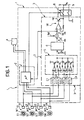
- the number 1 in figure 1 indicates as a whole an apparatus according to the invention for generating a reference signal v r indicating the speed of travel of a railway or tramway vehicle provided with an air-operated braking system and including a control system 2, in particular an anti-wheelslip control system associated with a group of wheels on the vehicle.
- control system 2 comprises a plurality of speed sensors S1-S4, for example comprising respective magnetic or electromagnetic pickups P1-P4 associated with corresponding toothed wheels W1 capable of rotating in a synchronous manner with corresponding wheels R1-R4 on the vehicle.
- the pickups of sensors S1-S4 supply the respective outputs with pulsed signals the frequencies of which indicate the speed of rotation of the wheels R1-R4 with which they are associated.
- Sensors S1-S4 are connected to corresponding inputs of the control unit 2, implemented for example by the use of a microprocessor.
- Sensors S1-S4 are also connected to the input of an analogue processing circuit indicated as a whole by the number 3 in figure 1 . This circuit will be described in more detail in what follows.
- the control unit 2 is arranged to analyse the signals supplied by sensors S1-S4, and to activate in a manner known in itself an anti-wheelslip function, controlling by means of electrically operated valve devices indicated as a whole by the number 4 the application, maintaining and release of braking pressure to the braking elements associated with the wheels.
- the unit 2 is also arranged to calculate, by means of software, on the basis of the signals supplied by sensors S1-S4, a reference speed indicating the speed of travel of the vehicle.
- the analogue processing circuit 3 comprises a plurality of frequency/voltage converters C1-C4, connected in due order to the outputs of pickups P1-P4 of sensors S1-S4.
- the outputs of converters C1-C4 are connected in due order to corresponding inputs of a selection circuit indicated as a whole by the number 5, arranged to supply at its output a signal V 1 corresponding to the highest-value signal among those present at the outputs of said converter circuits C1-C4.
- the circuit 5 comprises four voltage-follower circuits, of a structure known in itself, the outputs of which are connected in parallel with each other to form the total output of this circuit 5.
- the voltage V 1 available at the output of the circuit 5 therefore indicates the highest speed value among the values indicated by the signals supplied by sensors S1-S4.
- circuit 5 The output of circuit 5 is connected to the input of a limiter circuit 6. This circuit is arranged to limit the negative value of the derivative of the speed indicated by the signal V 1 to a predefined value, substantially equal to the maximum deceleration permitted for the railway or tramway vehicle.
- the circuit 6 has one of the various circuit structures known in themselves, and its output is connected to an input of an analogue summing circuit 7.
- This summing circuit 7 adds to the voltage V 1 ' which is present at the output from the limiter circuit 6 an offset voltage V off having a predetermined constant value.
- the voltage V R at the output of the summing circuit is on the one hand applied to a voltage follower circuit VF being the output of the analogue processing circuit 3, and on the other is supplied to an input of the control unit 2 described previously.
- the control unit 2 is arranged to compare the value of the speed of travel of the vehicle indicated by the voltage V R with the reference speed value calculated correspondingly by means of software by the unit 2.
- this unit by means of a controlled switching device 8 connects the output of the analogue processing circuit 3 to output terminals 9 of the apparatus 1, enabling the voltage V R to be used, for example to give permission for opening the doors of the railway carriage when the signal V R indicates the fact that the speed of travel of the carriage is less than a predetermined value.
- the unit 2 disconnects by means of the switching device 8 the output terminals 9 from the output of the analogue processing circuit 3, thereby disabling the use of the reference speed signal generated by this analogue processing circuit.
- Figure 2 shows a system for generating a signal v R indicating the speed of travel of a railway vehicle comprising a plurality of groups of wheels, R11-R41, R12-R42, ..., R1N-R4N, with each of which is associated a respective control system including a corresponding group of speed sensors S11-S41, S12-S42, ..., S1N-S4N.
- each of the above-mentioned groups of wheels is associated a respective apparatus 11, 12, ..., 1N, each of which has a structure such as that of the apparatus 1 described previously with reference to figure 1 .
- the outputs of the apparatuses 11, 12, ..., 1N are connected to each other substantially in parallel, in such a way that at the common output represented by the terminals indicated by the number 10 in figure 2 there is present operationally a voltage V R which has the highest value among the output voltages v R1 , v R2 , ..., V RN available at the outputs of the various apparatuses 11, 12, ..., 1N.
- the common output 10-10 of the apparatuses 11, 12, ..., 1N is connected to the input of a receiver device indicated as a whole by the number 20 in figure 2 .
- This device comprises substantially an input filter 21, intended to filter out noise, the output of which is connected to the input of an amplifier 22.
- a voltage v R indicating the speed of travel of the vehicle is available at the output of the amplifier 22.
- the signal at the output of the filter 21 is compared with the offset voltage V off by means of a threshold comparator 23 comprised in the receiver device 20.
- This comparator supplies as its output a warning voltage v W when the signal at the input of the amplifier 22, which corresponds substantially to the voltage V R , becomes less than the offset voltage V off .
Landscapes
- Engineering & Computer Science (AREA)
- Mechanical Engineering (AREA)
- Electric Propulsion And Braking For Vehicles (AREA)
- Train Traffic Observation, Control, And Security (AREA)
- Regulating Braking Force (AREA)
Priority Applications (1)
| Application Number | Priority Date | Filing Date | Title |
|---|---|---|---|
| PL05104392T PL1600591T3 (pl) | 2004-05-25 | 2005-05-24 | Urządzenie i układ do generowania sygnału referencyjnego wskazującego prędkość pojazdu kolejowego lub tramwajowego |
Applications Claiming Priority (2)
| Application Number | Priority Date | Filing Date | Title |
|---|---|---|---|
| ITTO20040347 | 2004-05-25 | ||
| IT000347A ITTO20040347A1 (it) | 2004-05-25 | 2004-05-25 | Apparecchiatura e sistema per la generazione di un segnale di riferimento indicativo della velocita' di un veicolo ferroviario o ferrotranviario. |
Publications (2)
| Publication Number | Publication Date |
|---|---|
| EP1600591A1 EP1600591A1 (en) | 2005-11-30 |
| EP1600591B1 true EP1600591B1 (en) | 2009-10-21 |
Family
ID=34939950
Family Applications (1)
| Application Number | Title | Priority Date | Filing Date |
|---|---|---|---|
| EP05104392A Expired - Lifetime EP1600591B1 (en) | 2004-05-25 | 2005-05-24 | An apparatus and system for generating a reference signal indicating the speed of a railway or tramway vehicle |
Country Status (8)
| Country | Link |
|---|---|
| US (1) | US20050279553A1 (it) |
| EP (1) | EP1600591B1 (it) |
| AT (1) | ATE446432T1 (it) |
| DE (1) | DE602005017220D1 (it) |
| DK (1) | DK1600591T3 (it) |
| ES (1) | ES2332183T3 (it) |
| IT (1) | ITTO20040347A1 (it) |
| PL (1) | PL1600591T3 (it) |
Families Citing this family (1)
| Publication number | Priority date | Publication date | Assignee | Title |
|---|---|---|---|---|
| JP5808095B2 (ja) * | 2010-11-02 | 2015-11-10 | 日本ケーブル株式会社 | ケーブルカー車両の扉装置 |
Family Cites Families (15)
| Publication number | Priority date | Publication date | Assignee | Title |
|---|---|---|---|---|
| US4491917A (en) * | 1981-05-22 | 1985-01-01 | Vapor Corporation | Door control systems |
| DE3124398A1 (de) * | 1981-06-22 | 1982-12-30 | Wabco Westinghouse Fahrzeugbremsen GmbH, 3000 Hannover | Elektropneumatische tuersteuerung |
| US4679508A (en) | 1986-02-21 | 1987-07-14 | Westinghouse Electric Corp. | Transit vehicle door control apparatus |
| US5244171A (en) | 1991-11-20 | 1993-09-14 | Westinghouse Air Brake Company | Intermediary wheel slip sequence speed processing system for multiple axle railway vehicles |
| US5406485A (en) * | 1993-11-09 | 1995-04-11 | Delco Electronics Corp. | Method and apparatus for detecting faulty operation of a wheel speed sensor |
| US5485379A (en) * | 1994-07-25 | 1996-01-16 | Kelsey Hayes Company | Method and system for detecting the proper functioning of an ABS control unit utilizing substantially identical programmed microprocessors |
| ES2113299B1 (es) * | 1995-10-11 | 1999-02-01 | Faiveley Espanola | Sistema de control para puertas automaticas. |
| US5788339A (en) * | 1997-01-28 | 1998-08-04 | Westinghouse Air Brake Company | Universal pneumatic brake control unit |
| DE19749015A1 (de) * | 1997-11-06 | 1999-05-12 | Wabco Gmbh | Verfahren zur Abstimmung von Bremskräften zwischen jeweils zwei miteinander verbundenen Teilen einer Fahrzeugeinheit |
| US5984426A (en) * | 1997-07-31 | 1999-11-16 | Westinghouse Air Brake Company | Apparatus and method for a railway freight car brake control |
| US6170923B1 (en) * | 1997-08-25 | 2001-01-09 | Aisin Seiki Kabushiki Kaisha | Malfunction detection device and method for a wheel speed sensor |
| US6353780B1 (en) * | 1999-06-29 | 2002-03-05 | Westinghouse Air Brake Technologies Corporation | Grade speed control and method for railway freight vehicle |
| US6194850B1 (en) * | 1999-08-23 | 2001-02-27 | General Electric Company | System and method for determining true ground speed in a locomotive |
| JP2001151030A (ja) * | 1999-11-30 | 2001-06-05 | Toyota Motor Corp | 開閉扉付き車載機器 |
| US7064507B2 (en) * | 2004-02-17 | 2006-06-20 | Railpower Technologies Corp. | Managing wheel skid in a locomotive |
-
2004
- 2004-05-25 IT IT000347A patent/ITTO20040347A1/it unknown
-
2005
- 2005-05-24 DK DK05104392.5T patent/DK1600591T3/da active
- 2005-05-24 US US11/135,335 patent/US20050279553A1/en not_active Abandoned
- 2005-05-24 DE DE602005017220T patent/DE602005017220D1/de not_active Expired - Lifetime
- 2005-05-24 ES ES05104392T patent/ES2332183T3/es not_active Expired - Lifetime
- 2005-05-24 AT AT05104392T patent/ATE446432T1/de not_active IP Right Cessation
- 2005-05-24 EP EP05104392A patent/EP1600591B1/en not_active Expired - Lifetime
- 2005-05-24 PL PL05104392T patent/PL1600591T3/pl unknown
Also Published As
| Publication number | Publication date |
|---|---|
| US20050279553A1 (en) | 2005-12-22 |
| PL1600591T3 (pl) | 2010-03-31 |
| DE602005017220D1 (de) | 2009-12-03 |
| ATE446432T1 (de) | 2009-11-15 |
| EP1600591A1 (en) | 2005-11-30 |
| ES2332183T3 (es) | 2010-01-28 |
| DK1600591T3 (da) | 2010-03-08 |
| ITTO20040347A1 (it) | 2004-08-25 |
Similar Documents
| Publication | Publication Date | Title |
|---|---|---|
| EP2191998B1 (en) | Controller for electric vehicle | |
| US20020074860A1 (en) | Device for the wireless transmission of a tripping signal for a restraint system | |
| US12099460B2 (en) | Wheel information transfer apparatus, wheel information transfer method and vehicle having wheel information transfer apparatus | |
| KR920006347B1 (ko) | 철도 차량용 제동제어장치 | |
| US3912034A (en) | Velocity comparison circuit for wheel slip control system | |
| EP2347925B1 (en) | Electric vehicle control device | |
| EP0834417B1 (en) | Speed control apparatus and method for electric car | |
| KR20170000860A (ko) | 자동열차방호장치 및 이를 포함하는 철도차량 | |
| EP1600591B1 (en) | An apparatus and system for generating a reference signal indicating the speed of a railway or tramway vehicle | |
| US8998147B2 (en) | Train control system with pulse-code-modulated cab signaling | |
| JP2010516547A (ja) | 乗員保護システムの起動制御のための制御機器及び方法 | |
| KR101964178B1 (ko) | 차량자세장치의 성능 검증을 위한 휠 모사 장치 | |
| US5654889A (en) | Simplified pattern recognition wheel slide protection | |
| KR20070119059A (ko) | 제어 장치와 분산형 데이터 처리 장치 사이의 데이터라인으로 데이터를 전송하기 위한 방법 및 장치 | |
| KR101611589B1 (ko) | 철도차량 제동 장치 및 방법 | |
| JP2012525039A (ja) | 乗り物用の選択的な装置作動を行うケーブルシステム | |
| JP5182571B2 (ja) | センサ信号処理装置 | |
| EP0897842A2 (en) | Universal wheel slip force control logic | |
| JP4544768B2 (ja) | エアバッグ展開用制御システム | |
| JPS6359905B2 (it) | ||
| KR100721385B1 (ko) | 차량용 제어기의 에러검출 제어방법 | |
| US7245993B2 (en) | Railway system with at least one track, and method for encoding data for transmission over the track | |
| KR20230147984A (ko) | 차량용 제동장치 및 이의 제어방법 | |
| US554307A (en) | Controller for electric motors | |
| RU2434761C1 (ru) | Устройство управления вагоном электропоезда |
Legal Events
| Date | Code | Title | Description |
|---|---|---|---|
| PUAI | Public reference made under article 153(3) epc to a published international application that has entered the european phase |
Free format text: ORIGINAL CODE: 0009012 |
|
| AK | Designated contracting states |
Kind code of ref document: A1 Designated state(s): AT BE BG CH CY CZ DE DK EE ES FI FR GB GR HU IE IS IT LI LT LU MC NL PL PT RO SE SI SK TR |
|
| AX | Request for extension of the european patent |
Extension state: AL BA HR LV MK YU |
|
| 17P | Request for examination filed |
Effective date: 20060216 |
|
| AKX | Designation fees paid |
Designated state(s): AT BE BG CH CY CZ DE DK EE ES FI FR GB GR HU IE IS IT LI LT LU MC NL PL PT RO SE SI SK TR |
|
| 17Q | First examination report despatched |
Effective date: 20080222 |
|
| GRAP | Despatch of communication of intention to grant a patent |
Free format text: ORIGINAL CODE: EPIDOSNIGR1 |
|
| GRAS | Grant fee paid |
Free format text: ORIGINAL CODE: EPIDOSNIGR3 |
|
| GRAA | (expected) grant |
Free format text: ORIGINAL CODE: 0009210 |
|
| RAP1 | Party data changed (applicant data changed or rights of an application transferred) |
Owner name: FAIVELEY TRANSPORT ITALIA S.P.A. |
|
| AK | Designated contracting states |
Kind code of ref document: B1 Designated state(s): AT BE BG CH CY CZ DE DK EE ES FI FR GB GR HU IE IS IT LI LT LU MC NL PL PT RO SE SI SK TR |
|
| REG | Reference to a national code |
Ref country code: GB Ref legal event code: FG4D |
|
| REG | Reference to a national code |
Ref country code: CH Ref legal event code: EP |
|
| REG | Reference to a national code |
Ref country code: IE Ref legal event code: FG4D |
|
| REF | Corresponds to: |
Ref document number: 602005017220 Country of ref document: DE Date of ref document: 20091203 Kind code of ref document: P |
|
| REG | Reference to a national code |
Ref country code: SE Ref legal event code: TRGR |
|
| REG | Reference to a national code |
Ref country code: ES Ref legal event code: FG2A Ref document number: 2332183 Country of ref document: ES Kind code of ref document: T3 |
|
| REG | Reference to a national code |
Ref country code: DK Ref legal event code: T3 |
|
| LTIE | Lt: invalidation of european patent or patent extension |
Effective date: 20091021 |
|
| REG | Reference to a national code |
Ref country code: PL Ref legal event code: T3 |
|
| NLV1 | Nl: lapsed or annulled due to failure to fulfill the requirements of art. 29p and 29m of the patents act | ||
| PG25 | Lapsed in a contracting state [announced via postgrant information from national office to epo] |
Ref country code: LT Free format text: LAPSE BECAUSE OF FAILURE TO SUBMIT A TRANSLATION OF THE DESCRIPTION OR TO PAY THE FEE WITHIN THE PRESCRIBED TIME-LIMIT Effective date: 20091021 Ref country code: IS Free format text: LAPSE BECAUSE OF FAILURE TO SUBMIT A TRANSLATION OF THE DESCRIPTION OR TO PAY THE FEE WITHIN THE PRESCRIBED TIME-LIMIT Effective date: 20100221 Ref country code: FI Free format text: LAPSE BECAUSE OF FAILURE TO SUBMIT A TRANSLATION OF THE DESCRIPTION OR TO PAY THE FEE WITHIN THE PRESCRIBED TIME-LIMIT Effective date: 20091021 Ref country code: PT Free format text: LAPSE BECAUSE OF FAILURE TO SUBMIT A TRANSLATION OF THE DESCRIPTION OR TO PAY THE FEE WITHIN THE PRESCRIBED TIME-LIMIT Effective date: 20100222 |
|
| PG25 | Lapsed in a contracting state [announced via postgrant information from national office to epo] |
Ref country code: SI Free format text: LAPSE BECAUSE OF FAILURE TO SUBMIT A TRANSLATION OF THE DESCRIPTION OR TO PAY THE FEE WITHIN THE PRESCRIBED TIME-LIMIT Effective date: 20091021 |
|
| PG25 | Lapsed in a contracting state [announced via postgrant information from national office to epo] |
Ref country code: AT Free format text: LAPSE BECAUSE OF FAILURE TO SUBMIT A TRANSLATION OF THE DESCRIPTION OR TO PAY THE FEE WITHIN THE PRESCRIBED TIME-LIMIT Effective date: 20091021 Ref country code: BE Free format text: LAPSE BECAUSE OF FAILURE TO SUBMIT A TRANSLATION OF THE DESCRIPTION OR TO PAY THE FEE WITHIN THE PRESCRIBED TIME-LIMIT Effective date: 20091021 |
|
| PG25 | Lapsed in a contracting state [announced via postgrant information from national office to epo] |
Ref country code: RO Free format text: LAPSE BECAUSE OF FAILURE TO SUBMIT A TRANSLATION OF THE DESCRIPTION OR TO PAY THE FEE WITHIN THE PRESCRIBED TIME-LIMIT Effective date: 20091021 Ref country code: BG Free format text: LAPSE BECAUSE OF FAILURE TO SUBMIT A TRANSLATION OF THE DESCRIPTION OR TO PAY THE FEE WITHIN THE PRESCRIBED TIME-LIMIT Effective date: 20100121 Ref country code: EE Free format text: LAPSE BECAUSE OF FAILURE TO SUBMIT A TRANSLATION OF THE DESCRIPTION OR TO PAY THE FEE WITHIN THE PRESCRIBED TIME-LIMIT Effective date: 20091021 |
|
| PLBE | No opposition filed within time limit |
Free format text: ORIGINAL CODE: 0009261 |
|
| STAA | Information on the status of an ep patent application or granted ep patent |
Free format text: STATUS: NO OPPOSITION FILED WITHIN TIME LIMIT |
|
| PG25 | Lapsed in a contracting state [announced via postgrant information from national office to epo] |
Ref country code: CZ Free format text: LAPSE BECAUSE OF FAILURE TO SUBMIT A TRANSLATION OF THE DESCRIPTION OR TO PAY THE FEE WITHIN THE PRESCRIBED TIME-LIMIT Effective date: 20091021 Ref country code: SK Free format text: LAPSE BECAUSE OF FAILURE TO SUBMIT A TRANSLATION OF THE DESCRIPTION OR TO PAY THE FEE WITHIN THE PRESCRIBED TIME-LIMIT Effective date: 20091021 |
|
| 26N | No opposition filed |
Effective date: 20100722 |
|
| PG25 | Lapsed in a contracting state [announced via postgrant information from national office to epo] |
Ref country code: GR Free format text: LAPSE BECAUSE OF FAILURE TO SUBMIT A TRANSLATION OF THE DESCRIPTION OR TO PAY THE FEE WITHIN THE PRESCRIBED TIME-LIMIT Effective date: 20100122 |
|
| PG25 | Lapsed in a contracting state [announced via postgrant information from national office to epo] |
Ref country code: MC Free format text: LAPSE BECAUSE OF NON-PAYMENT OF DUE FEES Effective date: 20100531 |
|
| REG | Reference to a national code |
Ref country code: CH Ref legal event code: PL |
|
| PG25 | Lapsed in a contracting state [announced via postgrant information from national office to epo] |
Ref country code: LI Free format text: LAPSE BECAUSE OF NON-PAYMENT OF DUE FEES Effective date: 20100531 Ref country code: CH Free format text: LAPSE BECAUSE OF NON-PAYMENT OF DUE FEES Effective date: 20100531 |
|
| PG25 | Lapsed in a contracting state [announced via postgrant information from national office to epo] |
Ref country code: IT Free format text: LAPSE BECAUSE OF FAILURE TO SUBMIT A TRANSLATION OF THE DESCRIPTION OR TO PAY THE FEE WITHIN THE PRESCRIBED TIME-LIMIT Effective date: 20091021 |
|
| PG25 | Lapsed in a contracting state [announced via postgrant information from national office to epo] |
Ref country code: IE Free format text: LAPSE BECAUSE OF NON-PAYMENT OF DUE FEES Effective date: 20100524 |
|
| PG25 | Lapsed in a contracting state [announced via postgrant information from national office to epo] |
Ref country code: CY Free format text: LAPSE BECAUSE OF FAILURE TO SUBMIT A TRANSLATION OF THE DESCRIPTION OR TO PAY THE FEE WITHIN THE PRESCRIBED TIME-LIMIT Effective date: 20091021 |
|
| PG25 | Lapsed in a contracting state [announced via postgrant information from national office to epo] |
Ref country code: LU Free format text: LAPSE BECAUSE OF NON-PAYMENT OF DUE FEES Effective date: 20100524 Ref country code: HU Free format text: LAPSE BECAUSE OF FAILURE TO SUBMIT A TRANSLATION OF THE DESCRIPTION OR TO PAY THE FEE WITHIN THE PRESCRIBED TIME-LIMIT Effective date: 20100422 Ref country code: NL Free format text: LAPSE BECAUSE OF FAILURE TO SUBMIT A TRANSLATION OF THE DESCRIPTION OR TO PAY THE FEE WITHIN THE PRESCRIBED TIME-LIMIT Effective date: 20091021 |
|
| PG25 | Lapsed in a contracting state [announced via postgrant information from national office to epo] |
Ref country code: TR Free format text: LAPSE BECAUSE OF FAILURE TO SUBMIT A TRANSLATION OF THE DESCRIPTION OR TO PAY THE FEE WITHIN THE PRESCRIBED TIME-LIMIT Effective date: 20091021 |
|
| PGFP | Annual fee paid to national office [announced via postgrant information from national office to epo] |
Ref country code: GB Payment date: 20140521 Year of fee payment: 10 |
|
| PGFP | Annual fee paid to national office [announced via postgrant information from national office to epo] |
Ref country code: SE Payment date: 20140523 Year of fee payment: 10 Ref country code: ES Payment date: 20140526 Year of fee payment: 10 |
|
| PGFP | Annual fee paid to national office [announced via postgrant information from national office to epo] |
Ref country code: PL Payment date: 20140401 Year of fee payment: 10 Ref country code: DK Payment date: 20140521 Year of fee payment: 10 |
|
| PGFP | Annual fee paid to national office [announced via postgrant information from national office to epo] |
Ref country code: DE Payment date: 20140731 Year of fee payment: 10 |
|
| PGFP | Annual fee paid to national office [announced via postgrant information from national office to epo] |
Ref country code: FR Payment date: 20140602 Year of fee payment: 10 |
|
| REG | Reference to a national code |
Ref country code: DE Ref legal event code: R119 Ref document number: 602005017220 Country of ref document: DE |
|
| REG | Reference to a national code |
Ref country code: DK Ref legal event code: EBP Effective date: 20150531 |
|
| GBPC | Gb: european patent ceased through non-payment of renewal fee |
Effective date: 20150524 |
|
| REG | Reference to a national code |
Ref country code: FR Ref legal event code: ST Effective date: 20160129 |
|
| PG25 | Lapsed in a contracting state [announced via postgrant information from national office to epo] |
Ref country code: SE Free format text: LAPSE BECAUSE OF NON-PAYMENT OF DUE FEES Effective date: 20150525 |
|
| PG25 | Lapsed in a contracting state [announced via postgrant information from national office to epo] |
Ref country code: DE Free format text: LAPSE BECAUSE OF NON-PAYMENT OF DUE FEES Effective date: 20151201 Ref country code: DK Free format text: LAPSE BECAUSE OF NON-PAYMENT OF DUE FEES Effective date: 20150531 Ref country code: GB Free format text: LAPSE BECAUSE OF NON-PAYMENT OF DUE FEES Effective date: 20150524 |
|
| PG25 | Lapsed in a contracting state [announced via postgrant information from national office to epo] |
Ref country code: FR Free format text: LAPSE BECAUSE OF NON-PAYMENT OF DUE FEES Effective date: 20150601 |
|
| REG | Reference to a national code |
Ref country code: ES Ref legal event code: FD2A Effective date: 20160630 |
|
| PG25 | Lapsed in a contracting state [announced via postgrant information from national office to epo] |
Ref country code: ES Free format text: LAPSE BECAUSE OF NON-PAYMENT OF DUE FEES Effective date: 20150525 |
|
| PG25 | Lapsed in a contracting state [announced via postgrant information from national office to epo] |
Ref country code: PL Free format text: LAPSE BECAUSE OF NON-PAYMENT OF DUE FEES Effective date: 20150524 |