EP1599723B1 - Scanning-based detection of ionizing radiation - Google Patents
Scanning-based detection of ionizing radiation Download PDFInfo
- Publication number
- EP1599723B1 EP1599723B1 EP04716394.4A EP04716394A EP1599723B1 EP 1599723 B1 EP1599723 B1 EP 1599723B1 EP 04716394 A EP04716394 A EP 04716394A EP 1599723 B1 EP1599723 B1 EP 1599723B1
- Authority
- EP
- European Patent Office
- Prior art keywords
- detector unit
- ionizing radiation
- dimensional detector
- dimensional
- fan
- Prior art date
- Legal status (The legal status is an assumption and is not a legal conclusion. Google has not performed a legal analysis and makes no representation as to the accuracy of the status listed.)
- Expired - Lifetime
Links
- 230000005865 ionizing radiation Effects 0.000 title claims description 36
- 238000001514 detection method Methods 0.000 title claims description 9
- 230000005855 radiation Effects 0.000 claims description 29
- 238000003384 imaging method Methods 0.000 claims description 5
- 238000003491 array Methods 0.000 description 7
- 238000000034 method Methods 0.000 description 6
- CURLTUGMZLYLDI-UHFFFAOYSA-N Carbon dioxide Chemical compound O=C=O CURLTUGMZLYLDI-UHFFFAOYSA-N 0.000 description 4
- 239000004065 semiconductor Substances 0.000 description 4
- XUIMIQQOPSSXEZ-UHFFFAOYSA-N Silicon Chemical compound [Si] XUIMIQQOPSSXEZ-UHFFFAOYSA-N 0.000 description 3
- 229910052710 silicon Inorganic materials 0.000 description 3
- 239000010703 silicon Substances 0.000 description 3
- 230000003321 amplification Effects 0.000 description 2
- 229910002092 carbon dioxide Inorganic materials 0.000 description 2
- 239000001569 carbon dioxide Substances 0.000 description 2
- 239000011888 foil Substances 0.000 description 2
- 239000000203 mixture Substances 0.000 description 2
- 238000003199 nucleic acid amplification method Methods 0.000 description 2
- 239000000758 substrate Substances 0.000 description 2
- 230000001154 acute effect Effects 0.000 description 1
- 230000005540 biological transmission Effects 0.000 description 1
- 230000004907 flux Effects 0.000 description 1
- 229910052743 krypton Inorganic materials 0.000 description 1
- DNNSSWSSYDEUBZ-UHFFFAOYSA-N krypton atom Chemical compound [Kr] DNNSSWSSYDEUBZ-UHFFFAOYSA-N 0.000 description 1
- 239000007788 liquid Substances 0.000 description 1
- 238000005259 measurement Methods 0.000 description 1
- 238000012805 post-processing Methods 0.000 description 1
- 230000004044 response Effects 0.000 description 1
- 230000003595 spectral effect Effects 0.000 description 1
- 239000010409 thin film Substances 0.000 description 1
- WFKWXMTUELFFGS-UHFFFAOYSA-N tungsten Chemical compound [W] WFKWXMTUELFFGS-UHFFFAOYSA-N 0.000 description 1
- 229910052721 tungsten Inorganic materials 0.000 description 1
- 239000010937 tungsten Substances 0.000 description 1
- 229910052724 xenon Inorganic materials 0.000 description 1
- FHNFHKCVQCLJFQ-UHFFFAOYSA-N xenon atom Chemical compound [Xe] FHNFHKCVQCLJFQ-UHFFFAOYSA-N 0.000 description 1
Images


Classifications
-
- G—PHYSICS
- G01—MEASURING; TESTING
- G01N—INVESTIGATING OR ANALYSING MATERIALS BY DETERMINING THEIR CHEMICAL OR PHYSICAL PROPERTIES
- G01N23/00—Investigating or analysing materials by the use of wave or particle radiation, e.g. X-rays or neutrons, not covered by groups G01N3/00 – G01N17/00, G01N21/00 or G01N22/00
- G01N23/02—Investigating or analysing materials by the use of wave or particle radiation, e.g. X-rays or neutrons, not covered by groups G01N3/00 – G01N17/00, G01N21/00 or G01N22/00 by transmitting the radiation through the material
-
- G—PHYSICS
- G21—NUCLEAR PHYSICS; NUCLEAR ENGINEERING
- G21K—TECHNIQUES FOR HANDLING PARTICLES OR IONISING RADIATION NOT OTHERWISE PROVIDED FOR; IRRADIATION DEVICES; GAMMA RAY OR X-RAY MICROSCOPES
- G21K5/00—Irradiation devices
- G21K5/10—Irradiation devices with provision for relative movement of beam source and object to be irradiated
-
- A—HUMAN NECESSITIES
- A61—MEDICAL OR VETERINARY SCIENCE; HYGIENE
- A61B—DIAGNOSIS; SURGERY; IDENTIFICATION
- A61B6/00—Apparatus for radiation diagnosis, e.g. combined with radiation therapy equipment
- A61B6/06—Diaphragms
-
- A—HUMAN NECESSITIES
- A61—MEDICAL OR VETERINARY SCIENCE; HYGIENE
- A61B—DIAGNOSIS; SURGERY; IDENTIFICATION
- A61B6/00—Apparatus for radiation diagnosis, e.g. combined with radiation therapy equipment
- A61B6/40—Apparatus for radiation diagnosis, e.g. combined with radiation therapy equipment with arrangements for generating radiation specially adapted for radiation diagnosis
- A61B6/4064—Apparatus for radiation diagnosis, e.g. combined with radiation therapy equipment with arrangements for generating radiation specially adapted for radiation diagnosis specially adapted for producing a particular type of beam
- A61B6/4071—Pencil beams
-
- A—HUMAN NECESSITIES
- A61—MEDICAL OR VETERINARY SCIENCE; HYGIENE
- A61B—DIAGNOSIS; SURGERY; IDENTIFICATION
- A61B6/00—Apparatus for radiation diagnosis, e.g. combined with radiation therapy equipment
- A61B6/40—Apparatus for radiation diagnosis, e.g. combined with radiation therapy equipment with arrangements for generating radiation specially adapted for radiation diagnosis
- A61B6/4064—Apparatus for radiation diagnosis, e.g. combined with radiation therapy equipment with arrangements for generating radiation specially adapted for radiation diagnosis specially adapted for producing a particular type of beam
- A61B6/4078—Fan-beams
-
- A—HUMAN NECESSITIES
- A61—MEDICAL OR VETERINARY SCIENCE; HYGIENE
- A61B—DIAGNOSIS; SURGERY; IDENTIFICATION
- A61B6/00—Apparatus for radiation diagnosis, e.g. combined with radiation therapy equipment
- A61B6/42—Apparatus for radiation diagnosis, e.g. combined with radiation therapy equipment with arrangements for detecting radiation specially adapted for radiation diagnosis
- A61B6/4208—Apparatus for radiation diagnosis, e.g. combined with radiation therapy equipment with arrangements for detecting radiation specially adapted for radiation diagnosis characterised by using a particular type of detector
-
- G—PHYSICS
- G01—MEASURING; TESTING
- G01N—INVESTIGATING OR ANALYSING MATERIALS BY DETERMINING THEIR CHEMICAL OR PHYSICAL PROPERTIES
- G01N23/00—Investigating or analysing materials by the use of wave or particle radiation, e.g. X-rays or neutrons, not covered by groups G01N3/00 – G01N17/00, G01N21/00 or G01N22/00
- G01N23/02—Investigating or analysing materials by the use of wave or particle radiation, e.g. X-rays or neutrons, not covered by groups G01N3/00 – G01N17/00, G01N21/00 or G01N22/00 by transmitting the radiation through the material
- G01N23/04—Investigating or analysing materials by the use of wave or particle radiation, e.g. X-rays or neutrons, not covered by groups G01N3/00 – G01N17/00, G01N21/00 or G01N22/00 by transmitting the radiation through the material and forming images of the material
-
- A—HUMAN NECESSITIES
- A61—MEDICAL OR VETERINARY SCIENCE; HYGIENE
- A61B—DIAGNOSIS; SURGERY; IDENTIFICATION
- A61B6/00—Apparatus for radiation diagnosis, e.g. combined with radiation therapy equipment
- A61B6/04—Positioning of patients; Tiltable beds or the like
- A61B6/0407—Supports, e.g. tables or beds, for the body or parts of the body
- A61B6/0414—Supports, e.g. tables or beds, for the body or parts of the body with compression means
-
- A—HUMAN NECESSITIES
- A61—MEDICAL OR VETERINARY SCIENCE; HYGIENE
- A61B—DIAGNOSIS; SURGERY; IDENTIFICATION
- A61B6/00—Apparatus for radiation diagnosis, e.g. combined with radiation therapy equipment
- A61B6/50—Clinical applications
- A61B6/502—Clinical applications involving diagnosis of breast, i.e. mammography
Definitions
- the invention relates generally to apparatuses and methods for scanning-based detection of radiation.
- Line detectors for detecting ionizing radiation are known in the art. While such detectors provide for instantaneous one-dimensional imaging, two-dimensional imaging can only be performed by means of scanning the line detector, and optionally the radiation source, in a direction traverse to the one- dimensional detector array. A one-dimensional image is typically recorded each time the line detector, and optionally the radiation source, has been moved a distance corresponding to the width of the radiation sensitive area of the line detector.
- Such scanning-based detection is time consuming and may be impractical if large areas should be imaged. Movement of the object being examined may occur during scanning, which could severely reduce the image quality obtained. Thus, the scanning should be made as fast as possible. The exposure, however, has still to be selected such that the images possess high signal-to-noise ratio and high dynamic range.
- the spatial resolution is often an important parameter. In many examinations it is desirable to obtain a spatial resolution, which is better than 100 microns, e. g. as good as 50 microns. This put very high demands on the detector being used-both in terms of a narrow radiation sensitive area and in terms of small readout elements or pixels. Alternatively or additionally, very high requirements are put on the radiation
- a main object of the invention is therefore to provide a scanning-based ionizing radiation detecting apparatus and method, which provide for measurement of extremely high spatial resolution, but where the strong requirements on the detector and the radiation source are relaxed.
- a further object of the invention is to provide such an apparatus and such a method, which enable a fast scanning across the object to be examined.
- a yet further object of the invention is to provide such an apparatus and such a method, which are reliable, accurate, and inexpensive.
- a one-dimensional detector unit with an ionizing radiation sensitive thickness which is larger than the thickness of a fan-shaped beam of ionizing radiation which is exposed to the detector unit; and by controlling the scanning by the one-dimensional detector unit to obtain a one-dimensional image of the fan-shaped beam of ionizing radiation at every n'th length unit of the scanning, where n is not lower than essentially half the thickness of the fan-shaped beam in that length unit, but lower than the thickness of the fan-shaped beam in the same length unit.
- a scanning-based detection is thereby achieved with high spatial resolution in the two-dimensional image recorded without the provision of extremely thin radiation beams, or extremely narrow detectors.
- the scanning step length n is preferably considerably lower than the thickness of the fan-shaped beam, and more preferably essentially half the thickness of the fan-shaped beam.
- the scanning step length is set to a value smaller than the radiation sensitive thickness of the one-dimensional detector unit, but not smaller than essentially half the radiation sensitive thickness of the one-dimensional detector unit.
- the one-dimensional detector unit is preferably, but not exclusively, a gaseous based parallel plate detector unit.
- Other detector units that may be used include diode arrays, scintillator based arrays, CCD arrays, TFT-and CMOS-based detectors, liquid detectors, and solid-state detectors, e. g. one-dimensional PIN-diode arrays with edge-on, near edge-on or perpendicular incidence of X-rays.
- Fig. 1 From top to bottom the apparatus in Fig. 1 comprises an X-ray source 11, a filter device 12, a fan beam collimator 13, an object table or holder 15, and a one-dimensional detector unit 16.
- the X-ray source 11 is a conventional X-ray tube having a cathode, which emits electrons, and an anode emitting X-rays in response to being struck by the electrons, wherein the tube has an operating voltage, which is the voltage drop between the anode and the cathode, a tube current, which is the current between the anode and the cathode, and a focal spot size, which is the projected area in the direction of the emitted X-rays of the anode, on which the electrons impinge (not explicitly illustrated).
- a typical focal spot dimension is 0.1-1 mm. From such X-ray source it is difficult to produce a high quality planar radiation beam of a thickness of about 50 microns.
- a filter device 12 is located just beneath the X-ray tube 11, which typically includes thin metallic foils acting as filters to absorb the lowest (and sometimes also the highest) energy photons, which do not contribute significantly to the image quality.
- the filter device may have variable spectral transmission characteristics.
- the fan beam collimator 13 may be a thin foil of e. g. tungsten with a narrow radiation transparent slit etched away.
- the slit is aligned with a corresponding line-shaped sensitive area or entrance slit of the detector unit 16 so that X-rays passing through the slit of the fan beam collimator 13 will reach the sensitive area or entrance slit of the detector unit 16.
- the width of the slit is indicated by btl in Fig. 2 . Since the fan-shaped beam is divergent its thickness bt2 when reaching the detector unit 16 is bigger (see Fig. 2 again).
- the beam thickness bt2 at the detector unit 16 will be about 100 microns.
- the length of the slit is adapted so that the beam has a beam width of suitable size, e. g. 30-50 mm, when reaching the detector unit 16.
- the detector unit 16 is illustrated in more detail in Fig. 2 and is oriented so that a planar or fan-shaped X-ray beam 24 can enter sideways between essentially planar cathode and anode arrangements.
- Each of the electrode arrangements includes an electrically conducting electrode layer 25,27 supported by a respective dielectric substrate 26,28, wherein the arrangements are oriented such that the conductive cathode 25 and anode 27 layers are facing each other.
- a radiation transparent window 30 is provided at the front end of the detector unit to form an entrance for the fan-shaped beam 24 to the detector unit 16.
- the dielectric substrates 26,28 and the window 30 define, together with a back end wall 29 and non-illustrated sidewalls, a gas-tight confinement capable of being filled with an ionizable gas or gas mixture.
- the electrode arrangements are arranged within an external gas-tight casing (not illustrated).
- the ionizable gas or gas mixture may e. g. comprise krypton and carbon dioxide or xenon and carbon dioxide.
- the detector unit 16 comprises further a readout arrangement including a one-dimensional array of individual readout elements (not explicitly illustrated) for recording a one-dimensional image of the fan-shaped beam 24.
- the readout arrangement is integrated with the anode arrangement.
- the detector unit 16 may also comprise capabilities for electron avalanche amplification in order to record very low flux of X-rays, or detect each single X-ray with high efficiency.
- the one-dimensional detector unit 16 has a maximum ionizing radiation sensitive thickness or height dt, i. e. a maximum thickness of a radiation beam, which is contributing considerably to the signals detected by the detector unit 16, which thickness or height is typically smaller than the distance between the conductive electrode layers 25,27 (irrespective of the thickness bt2 of the fan-shaped beam when reaching the detector unit 16).
- dt maximum ionizing radiation sensitive thickness or height
- the distance between the electrodes is 200-2000 microns
- the radiation sensitive thickness dt is 100-1500 microns
- the depth (i. e. length in the direction of the radiation beam 24) of the detector is 10-100 mm
- the thickness (i. e. length perpendicular to the plane of Fig. 2 ) of the detector is 20-200 mm.
- the detector unit is replaced by a detector arrangement comprising a plurality of one-dimensional detector units distributed in a one-or two-dimensional array.
- the fan beam collimator 13 is then replaced by a collimator with a plurality of narrow radiation transparent slits-one for each detector unit.
- the dimensions and orientations of the slits are such that each detector unit is exposed to a respective fan-shaped X-ray beam.
- the X-ray tube 11, the fan beam collimator 13 and the detector unit 16 are attached to a common E-arm 17, which in turn is rotatably attached to a vertical stand 18 by means of a spindle 19 approximately at the height of the X-ray tube 11.
- the X-ray tube 11, the fan beam collimator 13 and the detector unit 16 can be moved in a common pivoting movement relative to an examination object arranged on the object table 15 to scan the object and produce a two-dimensional image thereof.
- the pivoting movement is schematically indicated by arrow 23.
- the object table 15 is firmly attached to a support 20, which in turn is firmly attached to the vertical stand 18.
- the E-arm 17 is provided with a recess or similar in the E-arm 17 (illustrated by the dashed lines). During scanning, the object is kept still.
- Fig. 1 may be modified such that the object is moved during scanning, while the X-ray tube 11, the fan beam collimator 13 and the detector unit 16 are kept at rest.
- the detector apparatus comprises a microprocessor or computer 21 provided with suitable software for controlling the apparatus and readout and post-processing of the signals from the line detector unit 16 and a power supply 22 for supplying the detector unit and the microprocessor or computer 21 with power and for driving a step motor or similar housed in the vertical stand 18 for driving the spindle 19 and thus the E-arm 17.
- a microprocessor or computer 21 provided with suitable software for controlling the apparatus and readout and post-processing of the signals from the line detector unit 16 and a power supply 22 for supplying the detector unit and the microprocessor or computer 21 with power and for driving a step motor or similar housed in the vertical stand 18 for driving the spindle 19 and thus the E-arm 17.
- X-rays are emitted from the X-ray tube 11 and pass through the filter device 12. Only x-rays passing through the slit of the fan beam collimator 13 traverse the object. In the object, the X-ray photons can be transmitted, absorbed or scattered. The X-rays that are transmitted leave the object and enter into the detector unit 16 and are detected. From the detection a one-dimensional image of the object is formed.
- the E-arm 17, holding the X-ray source 11, the fan beam collimator 13 and the detector unit 16 are moved in a pivoting movement such that the detector unit scans across the object in a direction, which is essentially parallel with the object table 15.
- the detected signals are read out and stored in a memory of the microprocessor 21.
- the E-arm 17 is moved relative the object stepwise, and the one-dimensional detector unit 16 is detecting, while being still between the stepwise movements.
- each scanning step has the length ss as indicated at the arrow 23 in Fig. 2 .
- the microprocessor 21 is adapted to control the detections by the one-dimensional detector unit 16 during the scanning to obtain a one- dimensional image of the fan-shaped beam 24 of ionizing radiation at every n'th length unit ss of the movement, where n is not lower than essentially half the thickness bt2 in that length unit, but lower than the thickness bt2 in the same length unit.
- the scanning step ss can be defined as ⁇ 0.5 bt 2 ⁇ ss ⁇ bt 2 provided that bt 2 ⁇ dt
- Such provisions can assure a high spatial resolution in the two-dimensional image.
- the scanning step ss is considerably lower than the thickness bt2 of the fan-shaped beam 24 of ionizing radiation in the length unit to improve the spatial resolution in the two-dimensional image created from the number of one-dimensional images formed from the scanning.
- An optimum spatial resolution is obtained if the scanning step ss is essentially half the thickness bt2 of the fan-shaped beam 24 of ionizing radiation.
- the scanning step ss shall be lower, preferably considerably lower, than 100 microns, but not lower than about 50 microns. An optimum spatial resolution is obtained for a scanning step ss of 50 microns.
- the microprocessor 21 is adapted, according to the present invention, to control the detections by the one-dimensional detector unit 16 during the scanning to obtain a one-dimensional image of the fan-shaped beam 24 of ionizing radiation at every tilth length unit ss of the movement, where i is not lower than essentially half the ionizing radiation sensitive thickness dt of the one-dimensional detector unit 16 in the length unit, but lower than the ionizing radiation sensitive thickness dt in the same length unit.
- the scanning step ss can be defined as ⁇ 0.5 bt ⁇ ss ⁇ bt provided that bt 2 > dt
- the scanning step is preferably considerably lower than the radiation sensitive thickness dt, and more preferably essentially about half the radiation sensitive thickness dt.
- the scanning step length ss is between about 0.5 and 0.8 times, preferably between about 0.5 and 0.7 times, more preferably between about 0.5 and 0.6 times, and most preferably approximately 0.5 times, the thickness bt2 or the thickness/height/width dt, whichever is smallest.
- the spatial resolution is improved gradually (to the cost of longer scanning times) until the scanning step ss is equal to half the thickness bt2 or the thickness/height/width dt, whichever is smallest. If the scanning step is further reduced, no further improvement of the spatial resolution is obtained.
- the detector unit in the description above has been described as a gaseous-based ionization detector, wherein the freed electrons are drifted in a direction essentially perpendicular to the direction of the incident ionization
- the present invention is not limited to such a detector.
- any kind of detector can be used in the present invention as long as it is a one-dimensional detector capable of recording one-dimensional images of ionizing radiation, to which it is exposed.
- detectors are scintillator-based detectors, PIN-diode arrays, TFT (thin film transistor) arrays, CCD (charged coupled device) arrays, CMOS circuits, or any other type of semiconductor devices.
- Fig. 3 is a schematic enlarged cross-sectional view similar to the Fig. 2 cross-sectional view, but which illustrates a detector apparatus based on a linear semiconductor array 16'.
- the radiation sensitive thickness or width of the semiconductor array i. e. dimension orthogonal to the extension of the array, is indicated by dt. Note that this Figure illustrates the case where the thickness bt2 of the planar radiation beam 24 at the entrance of the pin diode array is larger than the linear semiconductor array width dt.
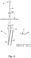
- Fig. 4 is a schematic enlarged cross-sectional view similar to the Figs. 2-3 . cross-sectional views, but which illustrates a detector apparatus based on a PIN-diode array 16''.
- the detector comprises a plate 31 of doped silicon carrying a uniform metallic layer 25''on one surface and a metallic multiple strip layer 27''on an opposite surface.
- the detector apparatus is tilted with respect to the incident radiation beam so that the beam impinges onto the uniform metallic layer 25'' of the detector apparatus at an acute angle.
- the incident radiation interacts with the matter whereupon electrons and holes are created.
- By applying a suitable voltage over the metallic layers 25'', 27''the electrons and holes are driven towards opposite surfaces of the silicon plate 31, and either ones of the electrons or holes are detected spatially resolved at the metallic multiple strip layer 27".
- Fig. 4 illustrates the case where the thickness bt2 of the planar radiation beam 24 at the entrance of the pin diode array is smaller than the active PIN-diode array width dt, which in turn depends on the depth of the PIN-diode array and the tilting angle.
- a further collimator is arranged in front of the detector (i. e. downstream of the object to be imaged), which may define the ionizing radiation sensitive thickness dt.
- the present invention is equally applicable for recording two-dimensional images of radiation as scattered off an object, instead of being transmitted there through.
Applications Claiming Priority (3)
| Application Number | Priority Date | Filing Date | Title |
|---|---|---|---|
| SE0300589A SE525517C2 (sv) | 2003-03-06 | 2003-03-06 | Anordning och förfarande för scanningbaserad detektering av joniserande strålning |
| SE0300589 | 2003-03-06 | ||
| PCT/SE2004/000278 WO2004080130A2 (en) | 2003-03-06 | 2004-03-02 | Scanning-based detection of ionizing radiation |
Publications (2)
| Publication Number | Publication Date |
|---|---|
| EP1599723A2 EP1599723A2 (en) | 2005-11-30 |
| EP1599723B1 true EP1599723B1 (en) | 2017-01-04 |
Family
ID=20290574
Family Applications (1)
| Application Number | Title | Priority Date | Filing Date |
|---|---|---|---|
| EP04716394.4A Expired - Lifetime EP1599723B1 (en) | 2003-03-06 | 2004-03-02 | Scanning-based detection of ionizing radiation |
Country Status (9)
| Country | Link |
|---|---|
| US (1) | US6970533B2 (sv) |
| EP (1) | EP1599723B1 (sv) |
| JP (1) | JP2006522331A (sv) |
| KR (1) | KR20060021817A (sv) |
| CN (1) | CN1756951A (sv) |
| AU (1) | AU2004217217A1 (sv) |
| CA (1) | CA2511097A1 (sv) |
| SE (1) | SE525517C2 (sv) |
| WO (1) | WO2004080130A2 (sv) |
Families Citing this family (6)
| Publication number | Priority date | Publication date | Assignee | Title |
|---|---|---|---|---|
| SE529961C2 (sv) * | 2006-03-21 | 2008-01-15 | Xcounter Ab | Avbildningsanordning och metod för att erhålla tidsupplöst avbildningsdata av ett objekt |
| SE529702C8 (sv) * | 2006-03-21 | 2007-11-27 | Scanningsbaserad detektering av joniserande strålning medelst dubbla källor | |
| SE0601068L (sv) * | 2006-05-12 | 2007-11-13 | Xcounter Ab | Multimodalitets röntgenavbildning |
| SE530549C2 (sv) * | 2006-10-31 | 2008-07-08 | Xcounter Ab | System för avbildning av ett bröst genom datortomografi |
| JP4883378B2 (ja) * | 2009-12-22 | 2012-02-22 | 横河電機株式会社 | 放射線検出装置 |
| CN105264360B (zh) * | 2013-04-04 | 2019-04-26 | 伊利诺斯工具制品有限公司 | 螺旋计算机断层成像 |
Citations (6)
| Publication number | Priority date | Publication date | Assignee | Title |
|---|---|---|---|---|
| JPH06265486A (ja) * | 1993-03-11 | 1994-09-22 | Toshiba Corp | X線ラインセンサ透視装置 |
| DE19813466A1 (de) * | 1997-04-21 | 1998-10-22 | Gen Electric | Verfahren und Vorrichtung zur Abtastung eines Gegenstands in einem Computer-Tomographie-System |
| WO1999023859A1 (en) * | 1997-11-03 | 1999-05-14 | Digiray Ab | A method and a device for planar beam radiography and a radiation detector |
| DE10122052A1 (de) * | 2000-05-08 | 2001-11-15 | Ge Med Sys Global Tech Co Llc | Verfahren und Vorrichtung zur Erzeugung von Dünn-Schnitt-Abbildungsdaten bei einem Mehrfachschnitt-Abbildungssystem |
| US6343110B1 (en) * | 2000-07-25 | 2002-01-29 | Ge Medical Systems Global Technology Company, Llc | Methods and apparatus for submillimeter CT slices with increased coverage |
| US6518578B1 (en) * | 1999-04-14 | 2003-02-11 | Xcounter Ab | Method for detecting ionizing radiation, a radiation detector and an apparatus for use in planar beam radiography |
Family Cites Families (17)
| Publication number | Priority date | Publication date | Assignee | Title |
|---|---|---|---|---|
| US4149247A (en) * | 1975-12-23 | 1979-04-10 | Varian Associates, Inc. | Tomographic apparatus and method for reconstructing planar slices from non-absorbed and non-scattered radiation |
| NL8004727A (nl) | 1980-08-21 | 1982-03-16 | Philips Nv | Stralingsonderzoekapparaat met spleetvormige bundel. |
| US4817123A (en) * | 1984-09-21 | 1989-03-28 | Picker International | Digital radiography detector resolution improvement |
| US4811373A (en) * | 1986-07-14 | 1989-03-07 | Hologic, Inc. | Bone densitometer |
| JPH084325B2 (ja) * | 1986-11-06 | 1996-01-17 | 松下電器産業株式会社 | 放射線受像装置 |
| US5025376A (en) | 1988-09-30 | 1991-06-18 | University Of Florida | Radiation teletherapy imaging system having plural ionization chambers |
| US5841833A (en) * | 1991-02-13 | 1998-11-24 | Lunar Corporation | Dual-energy x-ray detector providing spatial and temporal interpolation |
| GB2289983B (en) * | 1994-06-01 | 1996-10-16 | Simage Oy | Imaging devices,systems and methods |
| US5650626A (en) | 1996-07-16 | 1997-07-22 | Eastman Kodak Company | X-ray imaging detector with thickness and composition limited substrate |
| US6067342A (en) | 1997-10-30 | 2000-05-23 | Analogic Corporation | Digital filmless X-ray projection imaging system and method |
| SE514475C2 (sv) | 1999-04-14 | 2001-02-26 | Xcounter Ab | Strålningsdetektor, en anordning för användning vid radiografi med plant strålknippe och ett förfarande för detektering av joniserande strålning |
| SE514472C2 (sv) | 1999-04-14 | 2001-02-26 | Xcounter Ab | Strålningsdetektor och en anordning för användning vid radiografi |
| SE514443C2 (sv) | 1999-04-14 | 2001-02-26 | Xcounter Ab | Strålningsdetektor och en anordning för användning vid radiografi med plant strålknippe |
| SE0000957D0 (sv) | 2000-02-08 | 2000-03-21 | Digiray Ab | Detector and method for detection of ionizing radiation |
| SE0000793L (sv) | 2000-03-07 | 2001-09-08 | Xcounter Ab | Tomografianordning och -förfarande |
| SE530172C2 (sv) | 2000-03-31 | 2008-03-18 | Xcounter Ab | Spektralt upplöst detektering av joniserande strålning |
| JP2002148214A (ja) * | 2000-11-14 | 2002-05-22 | Ishida Co Ltd | X線検査装置 |
-
2003
- 2003-03-06 SE SE0300589A patent/SE525517C2/sv not_active IP Right Cessation
- 2003-04-11 US US10/411,100 patent/US6970533B2/en not_active Expired - Lifetime
-
2004
- 2004-03-02 JP JP2006507931A patent/JP2006522331A/ja active Pending
- 2004-03-02 EP EP04716394.4A patent/EP1599723B1/en not_active Expired - Lifetime
- 2004-03-02 CN CNA2004800060420A patent/CN1756951A/zh active Pending
- 2004-03-02 CA CA002511097A patent/CA2511097A1/en not_active Abandoned
- 2004-03-02 WO PCT/SE2004/000278 patent/WO2004080130A2/en active Application Filing
- 2004-03-02 KR KR1020057012387A patent/KR20060021817A/ko not_active Application Discontinuation
- 2004-03-02 AU AU2004217217A patent/AU2004217217A1/en not_active Abandoned
Patent Citations (6)
| Publication number | Priority date | Publication date | Assignee | Title |
|---|---|---|---|---|
| JPH06265486A (ja) * | 1993-03-11 | 1994-09-22 | Toshiba Corp | X線ラインセンサ透視装置 |
| DE19813466A1 (de) * | 1997-04-21 | 1998-10-22 | Gen Electric | Verfahren und Vorrichtung zur Abtastung eines Gegenstands in einem Computer-Tomographie-System |
| WO1999023859A1 (en) * | 1997-11-03 | 1999-05-14 | Digiray Ab | A method and a device for planar beam radiography and a radiation detector |
| US6518578B1 (en) * | 1999-04-14 | 2003-02-11 | Xcounter Ab | Method for detecting ionizing radiation, a radiation detector and an apparatus for use in planar beam radiography |
| DE10122052A1 (de) * | 2000-05-08 | 2001-11-15 | Ge Med Sys Global Tech Co Llc | Verfahren und Vorrichtung zur Erzeugung von Dünn-Schnitt-Abbildungsdaten bei einem Mehrfachschnitt-Abbildungssystem |
| US6343110B1 (en) * | 2000-07-25 | 2002-01-29 | Ge Medical Systems Global Technology Company, Llc | Methods and apparatus for submillimeter CT slices with increased coverage |
Non-Patent Citations (1)
| Title |
|---|
| BRUANDET J-P ET AL: "IMPROVING X-RAY IMAGES RESOLUTION USING SUBPIXEL SHIFTS OF THE DETECTOR", PROCEEDINGS OF SPIE, S P I E - INTERNATIONAL SOCIETY FOR OPTICAL ENGINEERING, US, vol. 3661, 22 February 1999 (1999-02-22), pages 1455 - 1465, XP008020637, ISSN: 0277-786X, ISBN: 978-1-62841-730-2, DOI: 10.1117/12.348546 * |
Also Published As
| Publication number | Publication date |
|---|---|
| AU2004217217A1 (en) | 2004-09-16 |
| KR20060021817A (ko) | 2006-03-08 |
| JP2006522331A (ja) | 2006-09-28 |
| WO2004080130A3 (en) | 2004-11-11 |
| US6970533B2 (en) | 2005-11-29 |
| SE525517C2 (sv) | 2005-03-01 |
| CA2511097A1 (en) | 2004-09-16 |
| SE0300589L (sv) | 2004-09-07 |
| WO2004080130A2 (en) | 2004-09-16 |
| US20040174947A1 (en) | 2004-09-09 |
| SE0300589D0 (sv) | 2003-03-06 |
| CN1756951A (zh) | 2006-04-05 |
| EP1599723A2 (en) | 2005-11-30 |
Similar Documents
| Publication | Publication Date | Title |
|---|---|---|
| US6784436B2 (en) | Radiation detector arrangement | |
| KR100690921B1 (ko) | 방사선 검출기와, 평면빔 방사선투과사진법에 이용하기위한 장치 및 이온화 방사선을 검출하기 위한 방법 | |
| AU2001290484B2 (en) | Apparatus for planar beam radiography and method of aligning an ionizing radiation detector with respect to a radiation source | |
| US7027561B2 (en) | Dual-energy scanning-based detection of ionizing radiation | |
| US6337482B1 (en) | Spectrally resolved detection of ionizing radiation | |
| AU2001290484A1 (en) | Apparatus for planar beam radiography and method of aligning an ionizing radiation detector with respect to a radiation source | |
| KR20020011382A (ko) | 방사선 검출기 및 방사선 사진법에서 이용하기 위한 장치 | |
| KR20020077423A (ko) | 이온화 방사선의 검출을 위한 검출기 및 방법 | |
| KR20040097164A (ko) | 스캐닝에 근거를 둔 전리 방사선 검출에 있어서의 노출 제어 | |
| KR20020011381A (ko) | 방사선 검출기 및 평면빔 방사선 사진법에서 이용하기위한 장치 | |
| AU2003206354B2 (en) | Arrangement and method for detection of ionizing radiation by a rotating detector array | |
| EP1599723B1 (en) | Scanning-based detection of ionizing radiation | |
| KR100806067B1 (ko) | 방사선 검출장치 및 방법 | |
| AU2001262880A1 (en) | Apparatus and method for radiation detection | |
| US20050078784A1 (en) | Scanning-based detection of ionizing radiation | |
| Bele et al. | New high‐DQE Imaging Plate scanner using the reflected readout laser signal for noise corrections |
Legal Events
| Date | Code | Title | Description |
|---|---|---|---|
| PUAI | Public reference made under article 153(3) epc to a published international application that has entered the european phase |
Free format text: ORIGINAL CODE: 0009012 |
|
| 17P | Request for examination filed |
Effective date: 20050820 |
|
| AK | Designated contracting states |
Kind code of ref document: A2 Designated state(s): AT BE BG CH CY CZ DE DK EE ES FI FR GB GR HU IE IT LI LU MC NL PL PT RO SE SI SK TR |
|
| AX | Request for extension of the european patent |
Extension state: AL LT LV MK |
|
| DAX | Request for extension of the european patent (deleted) | ||
| 17Q | First examination report despatched |
Effective date: 20070315 |
|
| REG | Reference to a national code |
Ref country code: DE Ref legal event code: R079 Ref document number: 602004050605 Country of ref document: DE Free format text: PREVIOUS MAIN CLASS: G01N0023020000 Ipc: G01N0023040000 |
|
| GRAP | Despatch of communication of intention to grant a patent |
Free format text: ORIGINAL CODE: EPIDOSNIGR1 |
|
| RIC1 | Information provided on ipc code assigned before grant |
Ipc: G01N 23/04 20060101AFI20160715BHEP Ipc: A61B 6/00 20060101ALI20160715BHEP Ipc: G21K 5/10 20060101ALI20160715BHEP |
|
| INTG | Intention to grant announced |
Effective date: 20160809 |
|
| GRAS | Grant fee paid |
Free format text: ORIGINAL CODE: EPIDOSNIGR3 |
|
| GRAA | (expected) grant |
Free format text: ORIGINAL CODE: 0009210 |
|
| AK | Designated contracting states |
Kind code of ref document: B1 Designated state(s): AT BE BG CH CY CZ DE DK EE ES FI FR GB GR HU IE IT LI LU MC NL PL PT RO SE SI SK TR |
|
| REG | Reference to a national code |
Ref country code: GB Ref legal event code: FG4D |
|
| REG | Reference to a national code |
Ref country code: CH Ref legal event code: EP |
|
| REG | Reference to a national code |
Ref country code: AT Ref legal event code: REF Ref document number: 859724 Country of ref document: AT Kind code of ref document: T Effective date: 20170115 |
|
| REG | Reference to a national code |
Ref country code: IE Ref legal event code: FG4D |
|
| REG | Reference to a national code |
Ref country code: DE Ref legal event code: R096 Ref document number: 602004050605 Country of ref document: DE |
|
| REG | Reference to a national code |
Ref country code: FR Ref legal event code: PLFP Year of fee payment: 14 |
|
| REG | Reference to a national code |
Ref country code: NL Ref legal event code: MP Effective date: 20170104 |
|
| REG | Reference to a national code |
Ref country code: AT Ref legal event code: MK05 Ref document number: 859724 Country of ref document: AT Kind code of ref document: T Effective date: 20170104 |
|
| PG25 | Lapsed in a contracting state [announced via postgrant information from national office to epo] |
Ref country code: NL Free format text: LAPSE BECAUSE OF FAILURE TO SUBMIT A TRANSLATION OF THE DESCRIPTION OR TO PAY THE FEE WITHIN THE PRESCRIBED TIME-LIMIT Effective date: 20170104 |
|
| PG25 | Lapsed in a contracting state [announced via postgrant information from national office to epo] |
Ref country code: FI Free format text: LAPSE BECAUSE OF FAILURE TO SUBMIT A TRANSLATION OF THE DESCRIPTION OR TO PAY THE FEE WITHIN THE PRESCRIBED TIME-LIMIT Effective date: 20170104 Ref country code: GR Free format text: LAPSE BECAUSE OF FAILURE TO SUBMIT A TRANSLATION OF THE DESCRIPTION OR TO PAY THE FEE WITHIN THE PRESCRIBED TIME-LIMIT Effective date: 20170405 |
|
| PG25 | Lapsed in a contracting state [announced via postgrant information from national office to epo] |
Ref country code: ES Free format text: LAPSE BECAUSE OF FAILURE TO SUBMIT A TRANSLATION OF THE DESCRIPTION OR TO PAY THE FEE WITHIN THE PRESCRIBED TIME-LIMIT Effective date: 20170104 Ref country code: AT Free format text: LAPSE BECAUSE OF FAILURE TO SUBMIT A TRANSLATION OF THE DESCRIPTION OR TO PAY THE FEE WITHIN THE PRESCRIBED TIME-LIMIT Effective date: 20170104 Ref country code: BG Free format text: LAPSE BECAUSE OF FAILURE TO SUBMIT A TRANSLATION OF THE DESCRIPTION OR TO PAY THE FEE WITHIN THE PRESCRIBED TIME-LIMIT Effective date: 20170404 Ref country code: SE Free format text: LAPSE BECAUSE OF FAILURE TO SUBMIT A TRANSLATION OF THE DESCRIPTION OR TO PAY THE FEE WITHIN THE PRESCRIBED TIME-LIMIT Effective date: 20170104 Ref country code: PL Free format text: LAPSE BECAUSE OF FAILURE TO SUBMIT A TRANSLATION OF THE DESCRIPTION OR TO PAY THE FEE WITHIN THE PRESCRIBED TIME-LIMIT Effective date: 20170104 Ref country code: PT Free format text: LAPSE BECAUSE OF FAILURE TO SUBMIT A TRANSLATION OF THE DESCRIPTION OR TO PAY THE FEE WITHIN THE PRESCRIBED TIME-LIMIT Effective date: 20170504 |
|
| REG | Reference to a national code |
Ref country code: DE Ref legal event code: R097 Ref document number: 602004050605 Country of ref document: DE |
|
| PG25 | Lapsed in a contracting state [announced via postgrant information from national office to epo] |
Ref country code: SK Free format text: LAPSE BECAUSE OF FAILURE TO SUBMIT A TRANSLATION OF THE DESCRIPTION OR TO PAY THE FEE WITHIN THE PRESCRIBED TIME-LIMIT Effective date: 20170104 Ref country code: IT Free format text: LAPSE BECAUSE OF FAILURE TO SUBMIT A TRANSLATION OF THE DESCRIPTION OR TO PAY THE FEE WITHIN THE PRESCRIBED TIME-LIMIT Effective date: 20170104 Ref country code: CZ Free format text: LAPSE BECAUSE OF FAILURE TO SUBMIT A TRANSLATION OF THE DESCRIPTION OR TO PAY THE FEE WITHIN THE PRESCRIBED TIME-LIMIT Effective date: 20170104 Ref country code: RO Free format text: LAPSE BECAUSE OF FAILURE TO SUBMIT A TRANSLATION OF THE DESCRIPTION OR TO PAY THE FEE WITHIN THE PRESCRIBED TIME-LIMIT Effective date: 20170104 Ref country code: EE Free format text: LAPSE BECAUSE OF FAILURE TO SUBMIT A TRANSLATION OF THE DESCRIPTION OR TO PAY THE FEE WITHIN THE PRESCRIBED TIME-LIMIT Effective date: 20170104 |
|
| REG | Reference to a national code |
Ref country code: CH Ref legal event code: PL |
|
| PLBE | No opposition filed within time limit |
Free format text: ORIGINAL CODE: 0009261 |
|
| STAA | Information on the status of an ep patent application or granted ep patent |
Free format text: STATUS: NO OPPOSITION FILED WITHIN TIME LIMIT |
|
| PG25 | Lapsed in a contracting state [announced via postgrant information from national office to epo] |
Ref country code: DK Free format text: LAPSE BECAUSE OF FAILURE TO SUBMIT A TRANSLATION OF THE DESCRIPTION OR TO PAY THE FEE WITHIN THE PRESCRIBED TIME-LIMIT Effective date: 20170104 Ref country code: MC Free format text: LAPSE BECAUSE OF FAILURE TO SUBMIT A TRANSLATION OF THE DESCRIPTION OR TO PAY THE FEE WITHIN THE PRESCRIBED TIME-LIMIT Effective date: 20170104 |
|
| 26N | No opposition filed |
Effective date: 20171005 |
|
| REG | Reference to a national code |
Ref country code: IE Ref legal event code: MM4A |
|
| PG25 | Lapsed in a contracting state [announced via postgrant information from national office to epo] |
Ref country code: LU Free format text: LAPSE BECAUSE OF NON-PAYMENT OF DUE FEES Effective date: 20170302 |
|
| PG25 | Lapsed in a contracting state [announced via postgrant information from national office to epo] |
Ref country code: SI Free format text: LAPSE BECAUSE OF FAILURE TO SUBMIT A TRANSLATION OF THE DESCRIPTION OR TO PAY THE FEE WITHIN THE PRESCRIBED TIME-LIMIT Effective date: 20170104 Ref country code: CH Free format text: LAPSE BECAUSE OF NON-PAYMENT OF DUE FEES Effective date: 20170331 Ref country code: IE Free format text: LAPSE BECAUSE OF NON-PAYMENT OF DUE FEES Effective date: 20170302 Ref country code: LI Free format text: LAPSE BECAUSE OF NON-PAYMENT OF DUE FEES Effective date: 20170331 |
|
| REG | Reference to a national code |
Ref country code: BE Ref legal event code: MM Effective date: 20170331 |
|
| REG | Reference to a national code |
Ref country code: FR Ref legal event code: PLFP Year of fee payment: 15 |
|
| PG25 | Lapsed in a contracting state [announced via postgrant information from national office to epo] |
Ref country code: BE Free format text: LAPSE BECAUSE OF NON-PAYMENT OF DUE FEES Effective date: 20170331 |
|
| PG25 | Lapsed in a contracting state [announced via postgrant information from national office to epo] |
Ref country code: HU Free format text: LAPSE BECAUSE OF FAILURE TO SUBMIT A TRANSLATION OF THE DESCRIPTION OR TO PAY THE FEE WITHIN THE PRESCRIBED TIME-LIMIT; INVALID AB INITIO Effective date: 20040302 |
|
| PG25 | Lapsed in a contracting state [announced via postgrant information from national office to epo] |
Ref country code: CY Free format text: LAPSE BECAUSE OF NON-PAYMENT OF DUE FEES Effective date: 20170104 |
|
| PG25 | Lapsed in a contracting state [announced via postgrant information from national office to epo] |
Ref country code: TR Free format text: LAPSE BECAUSE OF FAILURE TO SUBMIT A TRANSLATION OF THE DESCRIPTION OR TO PAY THE FEE WITHIN THE PRESCRIBED TIME-LIMIT Effective date: 20170104 |
|
| PGFP | Annual fee paid to national office [announced via postgrant information from national office to epo] |
Ref country code: FR Payment date: 20230222 Year of fee payment: 20 |
|
| PGFP | Annual fee paid to national office [announced via postgrant information from national office to epo] |
Ref country code: GB Payment date: 20230221 Year of fee payment: 20 Ref country code: DE Payment date: 20230221 Year of fee payment: 20 |
|
| P01 | Opt-out of the competence of the unified patent court (upc) registered |
Effective date: 20230528 |
|
| REG | Reference to a national code |
Ref country code: DE Ref legal event code: R071 Ref document number: 602004050605 Country of ref document: DE |
|
| REG | Reference to a national code |
Ref country code: GB Ref legal event code: PE20 Expiry date: 20240301 |
|
| PG25 | Lapsed in a contracting state [announced via postgrant information from national office to epo] |
Ref country code: GB Free format text: LAPSE BECAUSE OF EXPIRATION OF PROTECTION Effective date: 20240301 |