EP1599682B1 - Plaque support de garniture et procede de production de cette plaque - Google Patents
Plaque support de garniture et procede de production de cette plaque Download PDFInfo
- Publication number
- EP1599682B1 EP1599682B1 EP04790720A EP04790720A EP1599682B1 EP 1599682 B1 EP1599682 B1 EP 1599682B1 EP 04790720 A EP04790720 A EP 04790720A EP 04790720 A EP04790720 A EP 04790720A EP 1599682 B1 EP1599682 B1 EP 1599682B1
- Authority
- EP
- European Patent Office
- Prior art keywords
- support plate
- pins
- lining
- portions
- pattern
- Prior art date
- Legal status (The legal status is an assumption and is not a legal conclusion. Google has not performed a legal analysis and makes no representation as to the accuracy of the status listed.)
- Expired - Lifetime
Links
- 238000004519 manufacturing process Methods 0.000 title claims abstract description 11
- 239000000155 melt Substances 0.000 claims abstract description 19
- 238000005266 casting Methods 0.000 claims abstract description 11
- 239000000463 material Substances 0.000 claims abstract description 9
- 239000000206 moulding compound Substances 0.000 claims abstract 6
- 239000002184 metal Substances 0.000 claims abstract 2
- 229910052751 metal Inorganic materials 0.000 claims abstract 2
- 229910001018 Cast iron Inorganic materials 0.000 claims description 17
- 238000000034 method Methods 0.000 claims description 12
- OKTJSMMVPCPJKN-UHFFFAOYSA-N Carbon Chemical compound [C] OKTJSMMVPCPJKN-UHFFFAOYSA-N 0.000 claims description 8
- 229910002804 graphite Inorganic materials 0.000 claims description 8
- 239000010439 graphite Substances 0.000 claims description 8
- 239000011230 binding agent Substances 0.000 claims 2
- 150000001875 compounds Chemical class 0.000 description 22
- 238000000465 moulding Methods 0.000 description 22
- 239000000853 adhesive Substances 0.000 description 6
- 230000001070 adhesive effect Effects 0.000 description 6
- 238000004873 anchoring Methods 0.000 description 5
- 229910000831 Steel Inorganic materials 0.000 description 4
- 238000003825 pressing Methods 0.000 description 4
- 239000010959 steel Substances 0.000 description 4
- 238000005058 metal casting Methods 0.000 description 2
- 238000007711 solidification Methods 0.000 description 2
- 230000008023 solidification Effects 0.000 description 2
- 239000013585 weight reducing agent Substances 0.000 description 2
- KXGFMDJXCMQABM-UHFFFAOYSA-N 2-methoxy-6-methylphenol Chemical compound [CH]OC1=CC=CC([CH])=C1O KXGFMDJXCMQABM-UHFFFAOYSA-N 0.000 description 1
- 229910001141 Ductile iron Inorganic materials 0.000 description 1
- 238000005056 compaction Methods 0.000 description 1
- 238000010276 construction Methods 0.000 description 1
- 230000006378 damage Effects 0.000 description 1
- 238000013016 damping Methods 0.000 description 1
- 230000001419 dependent effect Effects 0.000 description 1
- 238000011161 development Methods 0.000 description 1
- 230000018109 developmental process Effects 0.000 description 1
- 238000007598 dipping method Methods 0.000 description 1
- 238000005538 encapsulation Methods 0.000 description 1
- 239000000446 fuel Substances 0.000 description 1
- 239000007789 gas Substances 0.000 description 1
- 230000005484 gravity Effects 0.000 description 1
- 238000010438 heat treatment Methods 0.000 description 1
- 238000010309 melting process Methods 0.000 description 1
- 239000012778 molding material Substances 0.000 description 1
- 239000005011 phenolic resin Substances 0.000 description 1
- 229920001568 phenolic resin Polymers 0.000 description 1
- 230000000704 physical effect Effects 0.000 description 1
- 238000000926 separation method Methods 0.000 description 1
- 238000007493 shaping process Methods 0.000 description 1
Images
Classifications
-
- F—MECHANICAL ENGINEERING; LIGHTING; HEATING; WEAPONS; BLASTING
- F16—ENGINEERING ELEMENTS AND UNITS; GENERAL MEASURES FOR PRODUCING AND MAINTAINING EFFECTIVE FUNCTIONING OF MACHINES OR INSTALLATIONS; THERMAL INSULATION IN GENERAL
- F16D—COUPLINGS FOR TRANSMITTING ROTATION; CLUTCHES; BRAKES
- F16D69/00—Friction linings; Attachment thereof; Selection of coacting friction substances or surfaces
- F16D69/04—Attachment of linings
- F16D2069/0425—Attachment methods or devices
- F16D2069/0433—Connecting elements not integral with the braking member, e.g. bolts, rivets
-
- F—MECHANICAL ENGINEERING; LIGHTING; HEATING; WEAPONS; BLASTING
- F16—ENGINEERING ELEMENTS AND UNITS; GENERAL MEASURES FOR PRODUCING AND MAINTAINING EFFECTIVE FUNCTIONING OF MACHINES OR INSTALLATIONS; THERMAL INSULATION IN GENERAL
- F16D—COUPLINGS FOR TRANSMITTING ROTATION; CLUTCHES; BRAKES
- F16D69/00—Friction linings; Attachment thereof; Selection of coacting friction substances or surfaces
- F16D69/04—Attachment of linings
- F16D2069/0425—Attachment methods or devices
- F16D2069/0441—Mechanical interlocking, e.g. roughened lining carrier, mating profiles on friction material and lining carrier
Definitions
- the invention relates to a method for producing a lining carrier plate. Furthermore, the invention relates to a lining carrier plate with a metal casting base plate having a support surface for receiving a Reibbelagsasse, wherein protrude from the support surface holding elements.
- Brake or clutch linings usually consist of a carrier plate with a pressed friction lining.
- an adhesive is often applied to the support plate before pressing the Reibbelagmasse.
- This adhesive is usually a phenolic resin based adhesive. Possibly. it is also possible to arrange an underlayer mass between the adhesive and the friction lining mass, which dampens vibrations occurring during the braking process.
- the support plate is in such brake or clutch linings made of steel.
- a disadvantage of the usual construction of a brake or clutch lining is, on the one hand, that the adhesive often does not withstand the high temperatures and shear forces occurring during braking in the friction lining.
- friction linings have been developed in which the connection between the carrier plate and the friction lining mass has been improved.
- holes can be made in the carrier plate. These can be filled with friction lining during pressing. In this way, a connection between the friction lining mass and the carrier plate, which holds the shear forces better, is produced.
- holding elements on the Reibbelagmasse side facing the carrier plate. This can be done by the holding elements are machined either from the backing plate material, for example in the form of a notch and / or a chip lift, or by the holding elements are applied to the carrier plate, for example in the form of welded or sintered grids or pins.
- the object of the present invention is to provide weight-reduced friction linings with an improved connection between a friction lining mass and a lining carrier plate.
- This object is achieved by a method for producing a lining carrier plate with the features of claim 1 or by a lining carrier plate with the features of claim 5 or by a method for producing a friction lining with the features of claim 9 or by a friction lining with the Characteristics of claim 10 solved.
- any body to be understood which extends over a given length such that it is releasably insertable over a portion of this length in a recess of the Belagaplattenmödells, for example, any at least partially cylindrical or conically shaped body.
- a weight reduction of the lining carrier plate is achieved. This is an increasingly important aspect of producing friction linings as the automotive industry strives to reduce the overall weight of their vehicles to reduce their fuel consumption. Furthermore, the weight reduction of the lining carrier plate causes a reduction in transport costs.
- pins offer the advantage over pouring protruding support members from the cast material itself (for example, through recesses in a molding compound due to protrusions of a support plate model, such as GB 2 303 891), that the material of the cast-in pins is so can be chosen that the pins can not be sheared off and are better anchored in the lining carrier plate.
- the recesses in the carrier plate model can be provided with a plurality of different pins.
- the pins introduced into the carrier plate model are designed such that the portions of the pins projecting out of the model have at least one section tapering towards the carrier carrier surface, ie. H. at least one undercut.
- the friction lining with the undercuts having pins so a positive connection between the Reibbelagsasse and the pins of the support plate is created, which is particularly suitable for receiving the shear forces occurring during the braking process.
- the sections of the pins introduced into the recesses of the carrier plate model at least partially have a contouring which is designed in such a way that the pins are releasably insertable into the carrier plate model.
- a contouring here is intended to deviate from a smooth-walled cylindrical or conical pin shape surface design of the pin sections be understood.
- the portions of the pins are grooved or threaded. As the melt is poured into the backing slab casting cavity, these portions of the pins projecting into the backing slab casting cavity are enclosed by the melt. As a result, a particularly good anchoring of the pins in the carrier plate is achieved.
- the melt forms a cast iron with vermicular graphite during solidification.
- the physical properties of vermicular graphite cast iron are between those of nodular cast iron and those of cast iron with lamellar graphite.
- the strength and toughness of the cast iron with vermicular graphite is higher than cast iron with flake graphite and on the other hand, the vibration damping better than cast iron with nodular graphite.
- a lining carrier plate with a metal casting base plate is further provided with a support surface for receiving a Reibbelagsasse, protruding from the support surface holding elements and the base plate is made of cast iron, proposed, which is characterized in that the holding elements are pins, which are cast in the base plate during their manufacture such that in each case a portion of the pins protrudes from the support surface of the base plate.
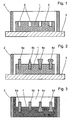
- FIG. 1 shows a schematic sectional view of a carrier plate model 1 inserted in a box 2.
- the carrier plate model 1 and the box 2 are arranged on a model plate 3.
- the carrier plate model 1 has on the upwardly facing side surface 5 a plurality of recesses 4.
- the recesses 4 may be evenly distributed over the side surface 5, but they may be arranged distributed differently densely in different sub-areas, the density of local braking forces may be dependent on braking.
- the recesses 4 are preferably holes of the same diameter (simple production). Alternatively, the recesses 4 in different areas of the side surface 5 may have different diameters.
- Figure 2 shows a schematic sectional view of the inserted into the box 2 support plate model 1 with introduced pins 6a-6d.
- the sections of the pins 6a-6d projecting from the carrier plate model 1 can be designed differently.
- the pins inserted in the recesses 4 are preferably of the same shape and size.
- the pins may be formed as a circular cylinder 6a or as to the end of the protruding from the support plate model 1 section tapered cylinder 6d.
- sections of the pins may have undercuts or may be at least partially formed club-shaped, as indicated at the pins 6c and 6d.
- the dipping into the support plate model 1 sections of the pins 6a-6d may be formed in a cylindrical shape with a smooth wall.
- these sections preferably have a contouring, d. H.
- d. H For example, circumferential grooves or a circumferential thread, as indicated at pin 6c.
- a molding compound 7 is applied to the carrier plate model 1. Subsequently, the applied Compress molding compound 7 and / or cured. This can be done for example by applying pressure to the molding compound. Moreover, it is possible to densify and / or cure the molding compound 7 by shaking and / or heating.
- the molding compound 7 After compaction and / or hardening of the molding compound 7, it is rotated by 180 ° with the box 2 and the carrier plate model 1 along the longitudinal axis of the model. Subsequently, the support plate model 1 is removed from the molding compound 7 such that the protruding in Figure 2 from the support plate model 1 sections of the pins 6a-6d remain in the molding compound 7. After removing the support plate model from the molding compound 7, this is covered with a second, pre-pressed and / or cured molding compound. The molding compound 7 and the second molding compound form a Suplatteng beauhohlraum 8.
- the second molding compound 7 has at least one riser and a sprue.
- the melt is now allowed to solidify such that a cast iron support plate, preferably a cast iron carrier plate with vermiculargraphite forms.
- a cast iron support plate preferably a cast iron carrier plate with vermiculargraphite forms.
- the cast iron support plate is removed from the mold. Steiger and sprue are separated from the cast iron support plate and still adhering molding compound is removed, for example by a sandblast.
- a covering of the molding compound 7 by a second mold can be omitted.
- the melt is then metered into the molding compound 7 poured.
Landscapes
- Engineering & Computer Science (AREA)
- General Engineering & Computer Science (AREA)
- Mechanical Engineering (AREA)
- Braking Arrangements (AREA)
- Moulding By Coating Moulds (AREA)
- Mounting, Exchange, And Manufacturing Of Dies (AREA)
- Moulds For Moulding Plastics Or The Like (AREA)
- Casting Or Compression Moulding Of Plastics Or The Like (AREA)
Claims (10)
- Procédé de fabrication d'une plaque de support de garniture, dans lequel :a) on prépare un modèle (1) de plaque de support, le modèle (1) de plaque de support présentant plusieurs découpes (6) sur une surface latérale (5) qui correspond à une surface de la plaque de support qui est tournée vers la garniture de frottement, et dans chacune desquelles une tige (6a - 6d) est insérée de telle sorte que la tige (6a - 6d) déborde en partie du modèle (1) de plaque de support,b) le modèle (1) de plaque de support et la partie des tiges (6a - 6d) qui déborde du modèle (1) de plaque de support sont englobés dans une pâte de moulage (7),
la pâte de moulage (7) est compactée et/ou durcie,
le modèle (1) de plaque de support est retiré de la pâte de moulage (7) compactée et/ou durcie de telle sorte que la partie des tiges (6a - 6d) qui déborde du modèle (1) de plaque de support reste dans la pâte de moulage (7) et que soit formé un espace creux (8) de coulée de plaque de support dans lequel les tiges (6a - 6d) pénètrent,c) une matière fondue est coulée dans l'espace creux (8) de coulée de plaque de support, la partie des tiges (6a - 6d) qui pénètre dans l'espace creux (8) de coulée de plaque de support étant englobée dans la matière fondue,d) la matière fondue est solidifiée de manière à former une plaque en fonte de support de garniture ete) la plaque de support de garniture est enlevée du moule. - Procédé selon la revendication 1, dans lequel les tiges (6a - 6d) introduites dans le modèle (1) de plaque de support sont configurées de telle sorte que la partie des tiges (6a - 6d) qui déborde du modèle (1) de plaque de support présente des contre-dépouilles.
- Procédé selon les revendications 1 ou 2, dans lequel la partie des tiges (6a - 6d) introduite dans les découpes ménagées dans le modèle (1) de plaque de support présente un contour.
- Procédé selon les revendications 1 à 3, caractérisé en ce que la matière fondue forme une fonte à graphite vermiculaire lors de sa solidification.
- Plaque de support de garniture dotée d'une plaque de base en métal coulé dont une surface de support sert à reprendre une pâte de garniture de frottement, dans laquelle des éléments de maintien débordent de la surface de support, la plaque de support étant fabriquée en fonte, caractérisée en ce que les éléments de maintien sont des tiges (6a - 6d) qui sont incorporées dans la plaque de base lors de sa fabrication de telle sorte qu'une partie de chaque tige (6a - 6d) déborde de la surface de support de la plaque de base.
- Plaque de support de garniture selon la revendication 5, caractérisée en ce que la plaque de base est fabriquée en fonte à graphite vermiculaire.
- Plaque de support de garniture selon les revendications 5 ou 6, caractérisée en ce que les tiges (6a - 6d) sont configurées de telle sorte que la partie des tiges (6a - 6d) qui déborde de la plaque de base présente des contre-dépouilles.
- Plaque de support de garniture selon l'une des revendications 5 à 7, caractérisée en ce que la partie des tiges (6a - 6d) incorporée dans la plaque de base lors de sa fabrication présente un contour.
- Procédé de fabrication d'une garniture de frottement, dans lequel on fabrique une plaque de support de garniture de frottement par un procédé selon l'une des revendications 1 à 4 et dans lequel on presse une pâte de garniture de frottement dotée d'un liant organique sur la surface latérale (5) de la plaque de support de garniture qui présente des tiges (6a - 6d).
- Garniture de frottement dotée d'une plaque de support de garniture selon l'une des revendications 5 à 8 et d'une pâte de garniture de frottement dans laquelle une pâte de garniture de frottement dotée d'un liant organique est pressée sur une surface de support.
Applications Claiming Priority (3)
| Application Number | Priority Date | Filing Date | Title |
|---|---|---|---|
| DE10350725A DE10350725B4 (de) | 2003-10-30 | 2003-10-30 | Belagträgerplatte und Verfahren zu deren Herstellung |
| DE10350725 | 2003-10-30 | ||
| PCT/EP2004/011915 WO2005042999A1 (fr) | 2003-10-30 | 2004-10-21 | Plaque support de garniture et procede de production de cette plaque |
Publications (2)
| Publication Number | Publication Date |
|---|---|
| EP1599682A1 EP1599682A1 (fr) | 2005-11-30 |
| EP1599682B1 true EP1599682B1 (fr) | 2006-09-27 |
Family
ID=34529930
Family Applications (1)
| Application Number | Title | Priority Date | Filing Date |
|---|---|---|---|
| EP04790720A Expired - Lifetime EP1599682B1 (fr) | 2003-10-30 | 2004-10-21 | Plaque support de garniture et procede de production de cette plaque |
Country Status (8)
| Country | Link |
|---|---|
| US (1) | US7810546B2 (fr) |
| EP (1) | EP1599682B1 (fr) |
| JP (1) | JP2007510108A (fr) |
| KR (1) | KR100806481B1 (fr) |
| AT (1) | ATE340950T1 (fr) |
| BR (1) | BRPI0416066A (fr) |
| DE (2) | DE10350725B4 (fr) |
| WO (1) | WO2005042999A1 (fr) |
Families Citing this family (8)
| Publication number | Priority date | Publication date | Assignee | Title |
|---|---|---|---|---|
| DE102008014550B4 (de) * | 2008-03-15 | 2011-12-15 | Meteor Umformtechnik Gmbh & Co. Kg | Trägerplatte für Bremsbeläge von Fahrzeugen |
| DE202009017931U1 (de) | 2009-03-03 | 2011-01-20 | Stanz- Und Umformtechnik Jancer Gmbh | Bremsbelagträgerrückhalteplatte |
| DE102010031889A1 (de) * | 2010-07-21 | 2012-01-26 | Jancer Vermögensverwaltungs Ug (Haftungsbeschränkt) & Co. Kg | Verfahren zum Herstellen eines Bremsbelagträgers |
| DE102012103196B4 (de) | 2012-03-26 | 2023-08-24 | ABC Advanced Brake Components | Bremsbelagträgerplatte und Verfahren zum Herstellen einer Bremsbelagträgerplatte |
| CN107096904B (zh) * | 2017-05-19 | 2019-04-26 | 扬州电力设备修造厂有限公司 | 一种生产耐磨复合衬板的方法 |
| DE102017209116A1 (de) * | 2017-05-31 | 2018-12-06 | Robert Bosch Gmbh | Bremsbelaganordnung, Verfahren |
| DE102020106296A1 (de) | 2020-03-09 | 2021-09-23 | Tmd Friction Services Gmbh | Belagträgerplatte für eine Scheibenbremse eines Kraftfahrzeugs sowie Verfahren zur deren Herstellung |
| GB2643107A (en) * | 2024-07-26 | 2026-02-11 | Tribol Braking Ltd | A backing plate mould |
Family Cites Families (10)
| Publication number | Priority date | Publication date | Assignee | Title |
|---|---|---|---|---|
| JPS5928786B2 (ja) * | 1976-10-29 | 1984-07-16 | トヨタ自動車株式会社 | デイスクブレ−キパツド |
| US4799579A (en) * | 1985-11-18 | 1989-01-24 | Myers Paul A | Clutch and brake friction assembly and method of making same |
| JPH0617700B2 (ja) * | 1990-11-07 | 1994-03-09 | 川崎重工業株式会社 | ブレーキディスク材 |
| JPH068138U (ja) * | 1992-07-09 | 1994-02-01 | 曙ブレーキ工業株式会社 | 鉄道用制輪子 |
| GB9506032D0 (en) * | 1995-03-24 | 1995-05-10 | T & N Technology Ltd | Backplate for friction material |
| GB9515926D0 (en) | 1995-08-03 | 1995-10-04 | T & N Technology Ltd | Manufacture of brake pads |
| DE19532019C1 (de) * | 1995-08-31 | 1997-02-13 | Ae Goetze Gmbh | Trägerplatte für Reibbeläge |
| JPH09111393A (ja) * | 1995-10-20 | 1997-04-28 | Hitachi Metals Ltd | ディスクブレーキ用ロータ材 |
| JPH11230208A (ja) * | 1998-02-17 | 1999-08-27 | Hitachi Chem Co Ltd | ディスクブレーキパッド用裏金及びその製造法並びに該裏金を用いたディスクブレーキパッド |
| DE29804619U1 (de) * | 1998-03-10 | 1998-06-04 | Obtec A/S, Svendborg | Bremsbacke für Scheibenbremsen |
-
2003
- 2003-10-30 DE DE10350725A patent/DE10350725B4/de not_active Expired - Fee Related
-
2004
- 2004-10-21 KR KR1020067008441A patent/KR100806481B1/ko not_active Expired - Fee Related
- 2004-10-21 EP EP04790720A patent/EP1599682B1/fr not_active Expired - Lifetime
- 2004-10-21 JP JP2006537138A patent/JP2007510108A/ja active Pending
- 2004-10-21 BR BRPI0416066-5A patent/BRPI0416066A/pt not_active IP Right Cessation
- 2004-10-21 US US10/577,248 patent/US7810546B2/en not_active Expired - Fee Related
- 2004-10-21 WO PCT/EP2004/011915 patent/WO2005042999A1/fr not_active Ceased
- 2004-10-21 AT AT04790720T patent/ATE340950T1/de not_active IP Right Cessation
- 2004-10-21 DE DE502004001606T patent/DE502004001606D1/de not_active Expired - Lifetime
Also Published As
| Publication number | Publication date |
|---|---|
| DE10350725B4 (de) | 2006-10-12 |
| ATE340950T1 (de) | 2006-10-15 |
| KR100806481B1 (ko) | 2008-02-21 |
| KR20060093340A (ko) | 2006-08-24 |
| US7810546B2 (en) | 2010-10-12 |
| EP1599682A1 (fr) | 2005-11-30 |
| BRPI0416066A (pt) | 2008-03-04 |
| DE502004001606D1 (de) | 2006-11-09 |
| DE10350725A1 (de) | 2005-06-09 |
| JP2007510108A (ja) | 2007-04-19 |
| WO2005042999A1 (fr) | 2005-05-12 |
| US20070215305A1 (en) | 2007-09-20 |
Similar Documents
| Publication | Publication Date | Title |
|---|---|---|
| DE69602602T2 (de) | Herstellung von bremsklötzen | |
| EP1211231B1 (fr) | Procédé de fabrication d'un corps de friction en carbone poreux infiltré par du silicium et renforcé par des fibres de carbone et utilisation d'un tel corps de friction | |
| DE602004000859T2 (de) | Verbessertes zuführelement und system für metallguss | |
| EP0777830B1 (fr) | Etrier pour frein a disque | |
| DE102008052697A1 (de) | Einsätze mit Öffnungen für gedämpfte Produkte und Verfahren zur Herstellung sowie deren Verwendung | |
| DE19532019C1 (de) | Trägerplatte für Reibbeläge | |
| EP1599682B1 (fr) | Plaque support de garniture et procede de production de cette plaque | |
| DE4212558A1 (de) | Verstaerktes leichtmetallerzeugnis und verfahren zu seiner herstellung | |
| DE102007044744B4 (de) | Bremsklotz für Schienenfahrzeuge | |
| DE102009034043B4 (de) | Reibungsgedämpftes Produkt | |
| DE1475351A1 (de) | Einstueckige Einheit aus Kolben und Bremsbelag fuer Scheibenbremsen | |
| DE69216018T2 (de) | Zu umgiessende Auskleidung auf Eisenbasis | |
| EP2252444B1 (fr) | Dispositif pour fabriquer des garnitures de friction | |
| EP1256741B1 (fr) | Patin de frein ou d'embrayage et son procédé de fabrication | |
| DE2707901A1 (de) | Exzenterschnecke fuer exzenterschneckenpumpen und verfahren zu ihrer herstellung | |
| DE202004021109U1 (de) | Zuführelement und System für den Metallguss | |
| DE9209400U1 (de) | Steigerhülse | |
| DE2916211A1 (de) | Verfahren zur herstellung einer feuerfesten giessereiform | |
| EP1900961A2 (fr) | Disque de frein et procédé destiné à la fabrication du disque de frein | |
| DE202009012778U1 (de) | Verbundbremsklotzsohle und Verbundbremsklotz | |
| DE102024002429A1 (de) | Verfahren zum Einpressen einer Gewindebuchse in ein metallisches Gussbauteil und das metallische Gussbauteil | |
| DE102007037931A1 (de) | Gießform für den Kokillenguss | |
| DE102019115587A1 (de) | Trägerplatte mit Verankerungsrippen, Verfahren zur Herstellung einer Trägerplatte | |
| DE102022003072A1 (de) | Verfahren zur Herstellung eines Sandkernes zum Einsatz in Gussformen | |
| DE1508612C (de) | Gießform zum Gießen eines Metallguß teiles |
Legal Events
| Date | Code | Title | Description |
|---|---|---|---|
| PUAI | Public reference made under article 153(3) epc to a published international application that has entered the european phase |
Free format text: ORIGINAL CODE: 0009012 |
|
| 17P | Request for examination filed |
Effective date: 20050422 |
|
| AK | Designated contracting states |
Kind code of ref document: A1 Designated state(s): AT BE BG CH CY CZ DE DK EE ES FI FR GB GR HU IE IT LI LU MC NL PL PT RO SE SI SK TR |
|
| AX | Request for extension of the european patent |
Extension state: AL HR LT LV MK |
|
| GRAP | Despatch of communication of intention to grant a patent |
Free format text: ORIGINAL CODE: EPIDOSNIGR1 |
|
| GRAS | Grant fee paid |
Free format text: ORIGINAL CODE: EPIDOSNIGR3 |
|
| GRAA | (expected) grant |
Free format text: ORIGINAL CODE: 0009210 |
|
| AK | Designated contracting states |
Kind code of ref document: B1 Designated state(s): AT BE BG CH CY CZ DE DK EE ES FI FR GB GR HU IE IT LI LU MC NL PL PT RO SE SI SK TR |
|
| DAX | Request for extension of the european patent (deleted) | ||
| PG25 | Lapsed in a contracting state [announced via postgrant information from national office to epo] |
Ref country code: IT Free format text: LAPSE BECAUSE OF FAILURE TO SUBMIT A TRANSLATION OF THE DESCRIPTION OR TO PAY THE FEE WITHIN THE PRESCRIBED TIME-LIMIT;WARNING: LAPSES OF ITALIAN PATENTS WITH EFFECTIVE DATE BEFORE 2007 MAY HAVE OCCURRED AT ANY TIME BEFORE 2007. THE CORRECT EFFECTIVE DATE MAY BE DIFFERENT FROM THE ONE RECORDED. Effective date: 20060927 Ref country code: PL Free format text: LAPSE BECAUSE OF FAILURE TO SUBMIT A TRANSLATION OF THE DESCRIPTION OR TO PAY THE FEE WITHIN THE PRESCRIBED TIME-LIMIT Effective date: 20060927 Ref country code: NL Free format text: LAPSE BECAUSE OF FAILURE TO SUBMIT A TRANSLATION OF THE DESCRIPTION OR TO PAY THE FEE WITHIN THE PRESCRIBED TIME-LIMIT Effective date: 20060927 Ref country code: SK Free format text: LAPSE BECAUSE OF FAILURE TO SUBMIT A TRANSLATION OF THE DESCRIPTION OR TO PAY THE FEE WITHIN THE PRESCRIBED TIME-LIMIT Effective date: 20060927 Ref country code: FI Free format text: LAPSE BECAUSE OF FAILURE TO SUBMIT A TRANSLATION OF THE DESCRIPTION OR TO PAY THE FEE WITHIN THE PRESCRIBED TIME-LIMIT Effective date: 20060927 Ref country code: IE Free format text: LAPSE BECAUSE OF FAILURE TO SUBMIT A TRANSLATION OF THE DESCRIPTION OR TO PAY THE FEE WITHIN THE PRESCRIBED TIME-LIMIT Effective date: 20060927 Ref country code: CZ Free format text: LAPSE BECAUSE OF FAILURE TO SUBMIT A TRANSLATION OF THE DESCRIPTION OR TO PAY THE FEE WITHIN THE PRESCRIBED TIME-LIMIT Effective date: 20060927 Ref country code: SI Free format text: LAPSE BECAUSE OF FAILURE TO SUBMIT A TRANSLATION OF THE DESCRIPTION OR TO PAY THE FEE WITHIN THE PRESCRIBED TIME-LIMIT Effective date: 20060927 Ref country code: RO Free format text: LAPSE BECAUSE OF FAILURE TO SUBMIT A TRANSLATION OF THE DESCRIPTION OR TO PAY THE FEE WITHIN THE PRESCRIBED TIME-LIMIT Effective date: 20060927 |
|
| REG | Reference to a national code |
Ref country code: GB Ref legal event code: FG4D Free format text: NOT ENGLISH |
|
| GBT | Gb: translation of ep patent filed (gb section 77(6)(a)/1977) |
Effective date: 20060927 |
|
| PG25 | Lapsed in a contracting state [announced via postgrant information from national office to epo] |
Ref country code: MC Free format text: LAPSE BECAUSE OF NON-PAYMENT OF DUE FEES Effective date: 20061031 |
|
| REG | Reference to a national code |
Ref country code: CH Ref legal event code: EP |
|
| REG | Reference to a national code |
Ref country code: IE Ref legal event code: FG4D Free format text: LANGUAGE OF EP DOCUMENT: GERMAN |
|
| REF | Corresponds to: |
Ref document number: 502004001606 Country of ref document: DE Date of ref document: 20061109 Kind code of ref document: P |
|
| PG25 | Lapsed in a contracting state [announced via postgrant information from national office to epo] |
Ref country code: BG Free format text: LAPSE BECAUSE OF FAILURE TO SUBMIT A TRANSLATION OF THE DESCRIPTION OR TO PAY THE FEE WITHIN THE PRESCRIBED TIME-LIMIT Effective date: 20061227 Ref country code: DK Free format text: LAPSE BECAUSE OF FAILURE TO SUBMIT A TRANSLATION OF THE DESCRIPTION OR TO PAY THE FEE WITHIN THE PRESCRIBED TIME-LIMIT Effective date: 20061227 Ref country code: SE Free format text: LAPSE BECAUSE OF FAILURE TO SUBMIT A TRANSLATION OF THE DESCRIPTION OR TO PAY THE FEE WITHIN THE PRESCRIBED TIME-LIMIT Effective date: 20061227 |
|
| PG25 | Lapsed in a contracting state [announced via postgrant information from national office to epo] |
Ref country code: ES Free format text: LAPSE BECAUSE OF FAILURE TO SUBMIT A TRANSLATION OF THE DESCRIPTION OR TO PAY THE FEE WITHIN THE PRESCRIBED TIME-LIMIT Effective date: 20070107 |
|
| ET | Fr: translation filed | ||
| NLV1 | Nl: lapsed or annulled due to failure to fulfill the requirements of art. 29p and 29m of the patents act | ||
| PG25 | Lapsed in a contracting state [announced via postgrant information from national office to epo] |
Ref country code: PT Free format text: LAPSE BECAUSE OF FAILURE TO SUBMIT A TRANSLATION OF THE DESCRIPTION OR TO PAY THE FEE WITHIN THE PRESCRIBED TIME-LIMIT Effective date: 20070313 |
|
| REG | Reference to a national code |
Ref country code: IE Ref legal event code: FD4D |
|
| PLBE | No opposition filed within time limit |
Free format text: ORIGINAL CODE: 0009261 |
|
| STAA | Information on the status of an ep patent application or granted ep patent |
Free format text: STATUS: NO OPPOSITION FILED WITHIN TIME LIMIT |
|
| 26N | No opposition filed |
Effective date: 20070628 |
|
| BERE | Be: lapsed |
Owner name: TMD FRICTION SERVICES G.M.B.H. Effective date: 20061031 |
|
| PG25 | Lapsed in a contracting state [announced via postgrant information from national office to epo] |
Ref country code: AT Free format text: LAPSE BECAUSE OF NON-PAYMENT OF DUE FEES Effective date: 20061021 |
|
| PG25 | Lapsed in a contracting state [announced via postgrant information from national office to epo] |
Ref country code: GR Free format text: LAPSE BECAUSE OF FAILURE TO SUBMIT A TRANSLATION OF THE DESCRIPTION OR TO PAY THE FEE WITHIN THE PRESCRIBED TIME-LIMIT Effective date: 20061228 |
|
| PG25 | Lapsed in a contracting state [announced via postgrant information from national office to epo] |
Ref country code: EE Free format text: LAPSE BECAUSE OF FAILURE TO SUBMIT A TRANSLATION OF THE DESCRIPTION OR TO PAY THE FEE WITHIN THE PRESCRIBED TIME-LIMIT Effective date: 20060927 |
|
| PG25 | Lapsed in a contracting state [announced via postgrant information from national office to epo] |
Ref country code: HU Free format text: LAPSE BECAUSE OF FAILURE TO SUBMIT A TRANSLATION OF THE DESCRIPTION OR TO PAY THE FEE WITHIN THE PRESCRIBED TIME-LIMIT Effective date: 20070328 Ref country code: LU Free format text: LAPSE BECAUSE OF NON-PAYMENT OF DUE FEES Effective date: 20061021 Ref country code: TR Free format text: LAPSE BECAUSE OF FAILURE TO SUBMIT A TRANSLATION OF THE DESCRIPTION OR TO PAY THE FEE WITHIN THE PRESCRIBED TIME-LIMIT Effective date: 20060927 |
|
| PG25 | Lapsed in a contracting state [announced via postgrant information from national office to epo] |
Ref country code: CY Free format text: LAPSE BECAUSE OF FAILURE TO SUBMIT A TRANSLATION OF THE DESCRIPTION OR TO PAY THE FEE WITHIN THE PRESCRIBED TIME-LIMIT Effective date: 20060927 |
|
| REG | Reference to a national code |
Ref country code: CH Ref legal event code: PL |
|
| PG25 | Lapsed in a contracting state [announced via postgrant information from national office to epo] |
Ref country code: BE Free format text: LAPSE BECAUSE OF FAILURE TO SUBMIT A TRANSLATION OF THE DESCRIPTION OR TO PAY THE FEE WITHIN THE PRESCRIBED TIME-LIMIT Effective date: 20061031 |
|
| PG25 | Lapsed in a contracting state [announced via postgrant information from national office to epo] |
Ref country code: LI Free format text: LAPSE BECAUSE OF NON-PAYMENT OF DUE FEES Effective date: 20081031 Ref country code: CH Free format text: LAPSE BECAUSE OF NON-PAYMENT OF DUE FEES Effective date: 20081031 |
|
| PGFP | Annual fee paid to national office [announced via postgrant information from national office to epo] |
Ref country code: DE Payment date: 20131031 Year of fee payment: 10 Ref country code: FR Payment date: 20131022 Year of fee payment: 10 Ref country code: GB Payment date: 20131021 Year of fee payment: 10 |
|
| PGFP | Annual fee paid to national office [announced via postgrant information from national office to epo] |
Ref country code: IT Payment date: 20131024 Year of fee payment: 10 |
|
| REG | Reference to a national code |
Ref country code: DE Ref legal event code: R119 Ref document number: 502004001606 Country of ref document: DE |
|
| GBPC | Gb: european patent ceased through non-payment of renewal fee |
Effective date: 20141021 |
|
| PG25 | Lapsed in a contracting state [announced via postgrant information from national office to epo] |
Ref country code: GB Free format text: LAPSE BECAUSE OF NON-PAYMENT OF DUE FEES Effective date: 20141021 Ref country code: DE Free format text: LAPSE BECAUSE OF NON-PAYMENT OF DUE FEES Effective date: 20150501 |
|
| REG | Reference to a national code |
Ref country code: FR Ref legal event code: ST Effective date: 20150630 |
|
| PG25 | Lapsed in a contracting state [announced via postgrant information from national office to epo] |
Ref country code: IT Free format text: LAPSE BECAUSE OF NON-PAYMENT OF DUE FEES Effective date: 20141021 Ref country code: FR Free format text: LAPSE BECAUSE OF NON-PAYMENT OF DUE FEES Effective date: 20141031 |