EP1599682B1 - Lining support plate and associated production method - Google Patents
Lining support plate and associated production method Download PDFInfo
- Publication number
- EP1599682B1 EP1599682B1 EP04790720A EP04790720A EP1599682B1 EP 1599682 B1 EP1599682 B1 EP 1599682B1 EP 04790720 A EP04790720 A EP 04790720A EP 04790720 A EP04790720 A EP 04790720A EP 1599682 B1 EP1599682 B1 EP 1599682B1
- Authority
- EP
- European Patent Office
- Prior art keywords
- support plate
- pins
- lining
- portions
- pattern
- Prior art date
- Legal status (The legal status is an assumption and is not a legal conclusion. Google has not performed a legal analysis and makes no representation as to the accuracy of the status listed.)
- Expired - Lifetime
Links
- 238000004519 manufacturing process Methods 0.000 title claims abstract description 11
- 239000000155 melt Substances 0.000 claims abstract description 19
- 238000005266 casting Methods 0.000 claims abstract description 11
- 239000000463 material Substances 0.000 claims abstract description 9
- 239000000206 moulding compound Substances 0.000 claims abstract 6
- 239000002184 metal Substances 0.000 claims abstract 2
- 229910052751 metal Inorganic materials 0.000 claims abstract 2
- 229910001018 Cast iron Inorganic materials 0.000 claims description 17
- 238000000034 method Methods 0.000 claims description 12
- OKTJSMMVPCPJKN-UHFFFAOYSA-N Carbon Chemical compound [C] OKTJSMMVPCPJKN-UHFFFAOYSA-N 0.000 claims description 8
- 229910002804 graphite Inorganic materials 0.000 claims description 8
- 239000010439 graphite Substances 0.000 claims description 8
- 239000011230 binding agent Substances 0.000 claims 2
- 150000001875 compounds Chemical class 0.000 description 22
- 238000000465 moulding Methods 0.000 description 22
- 239000000853 adhesive Substances 0.000 description 6
- 230000001070 adhesive effect Effects 0.000 description 6
- 238000004873 anchoring Methods 0.000 description 5
- 229910000831 Steel Inorganic materials 0.000 description 4
- 238000003825 pressing Methods 0.000 description 4
- 239000010959 steel Substances 0.000 description 4
- 238000005058 metal casting Methods 0.000 description 2
- 238000007711 solidification Methods 0.000 description 2
- 230000008023 solidification Effects 0.000 description 2
- 239000013585 weight reducing agent Substances 0.000 description 2
- KXGFMDJXCMQABM-UHFFFAOYSA-N 2-methoxy-6-methylphenol Chemical compound [CH]OC1=CC=CC([CH])=C1O KXGFMDJXCMQABM-UHFFFAOYSA-N 0.000 description 1
- 229910001141 Ductile iron Inorganic materials 0.000 description 1
- 238000005056 compaction Methods 0.000 description 1
- 238000010276 construction Methods 0.000 description 1
- 230000006378 damage Effects 0.000 description 1
- 238000013016 damping Methods 0.000 description 1
- 230000001419 dependent effect Effects 0.000 description 1
- 238000011161 development Methods 0.000 description 1
- 230000018109 developmental process Effects 0.000 description 1
- 238000007598 dipping method Methods 0.000 description 1
- 238000005538 encapsulation Methods 0.000 description 1
- 239000000446 fuel Substances 0.000 description 1
- 239000007789 gas Substances 0.000 description 1
- 230000005484 gravity Effects 0.000 description 1
- 238000010438 heat treatment Methods 0.000 description 1
- 238000010309 melting process Methods 0.000 description 1
- 239000012778 molding material Substances 0.000 description 1
- 239000005011 phenolic resin Substances 0.000 description 1
- 229920001568 phenolic resin Polymers 0.000 description 1
- 230000000704 physical effect Effects 0.000 description 1
- 238000000926 separation method Methods 0.000 description 1
- 238000007493 shaping process Methods 0.000 description 1
Images
Classifications
-
- F—MECHANICAL ENGINEERING; LIGHTING; HEATING; WEAPONS; BLASTING
- F16—ENGINEERING ELEMENTS AND UNITS; GENERAL MEASURES FOR PRODUCING AND MAINTAINING EFFECTIVE FUNCTIONING OF MACHINES OR INSTALLATIONS; THERMAL INSULATION IN GENERAL
- F16D—COUPLINGS FOR TRANSMITTING ROTATION; CLUTCHES; BRAKES
- F16D69/00—Friction linings; Attachment thereof; Selection of coacting friction substances or surfaces
- F16D69/04—Attachment of linings
- F16D2069/0425—Attachment methods or devices
- F16D2069/0433—Connecting elements not integral with the braking member, e.g. bolts, rivets
-
- F—MECHANICAL ENGINEERING; LIGHTING; HEATING; WEAPONS; BLASTING
- F16—ENGINEERING ELEMENTS AND UNITS; GENERAL MEASURES FOR PRODUCING AND MAINTAINING EFFECTIVE FUNCTIONING OF MACHINES OR INSTALLATIONS; THERMAL INSULATION IN GENERAL
- F16D—COUPLINGS FOR TRANSMITTING ROTATION; CLUTCHES; BRAKES
- F16D69/00—Friction linings; Attachment thereof; Selection of coacting friction substances or surfaces
- F16D69/04—Attachment of linings
- F16D2069/0425—Attachment methods or devices
- F16D2069/0441—Mechanical interlocking, e.g. roughened lining carrier, mating profiles on friction material and lining carrier
Definitions
- the invention relates to a method for producing a lining carrier plate. Furthermore, the invention relates to a lining carrier plate with a metal casting base plate having a support surface for receiving a Reibbelagsasse, wherein protrude from the support surface holding elements.
- Brake or clutch linings usually consist of a carrier plate with a pressed friction lining.
- an adhesive is often applied to the support plate before pressing the Reibbelagmasse.
- This adhesive is usually a phenolic resin based adhesive. Possibly. it is also possible to arrange an underlayer mass between the adhesive and the friction lining mass, which dampens vibrations occurring during the braking process.
- the support plate is in such brake or clutch linings made of steel.
- a disadvantage of the usual construction of a brake or clutch lining is, on the one hand, that the adhesive often does not withstand the high temperatures and shear forces occurring during braking in the friction lining.
- friction linings have been developed in which the connection between the carrier plate and the friction lining mass has been improved.
- holes can be made in the carrier plate. These can be filled with friction lining during pressing. In this way, a connection between the friction lining mass and the carrier plate, which holds the shear forces better, is produced.
- holding elements on the Reibbelagmasse side facing the carrier plate. This can be done by the holding elements are machined either from the backing plate material, for example in the form of a notch and / or a chip lift, or by the holding elements are applied to the carrier plate, for example in the form of welded or sintered grids or pins.
- the object of the present invention is to provide weight-reduced friction linings with an improved connection between a friction lining mass and a lining carrier plate.
- This object is achieved by a method for producing a lining carrier plate with the features of claim 1 or by a lining carrier plate with the features of claim 5 or by a method for producing a friction lining with the features of claim 9 or by a friction lining with the Characteristics of claim 10 solved.
- any body to be understood which extends over a given length such that it is releasably insertable over a portion of this length in a recess of the Belagaplattenmödells, for example, any at least partially cylindrical or conically shaped body.
- a weight reduction of the lining carrier plate is achieved. This is an increasingly important aspect of producing friction linings as the automotive industry strives to reduce the overall weight of their vehicles to reduce their fuel consumption. Furthermore, the weight reduction of the lining carrier plate causes a reduction in transport costs.
- pins offer the advantage over pouring protruding support members from the cast material itself (for example, through recesses in a molding compound due to protrusions of a support plate model, such as GB 2 303 891), that the material of the cast-in pins is so can be chosen that the pins can not be sheared off and are better anchored in the lining carrier plate.
- the recesses in the carrier plate model can be provided with a plurality of different pins.
- the pins introduced into the carrier plate model are designed such that the portions of the pins projecting out of the model have at least one section tapering towards the carrier carrier surface, ie. H. at least one undercut.
- the friction lining with the undercuts having pins so a positive connection between the Reibbelagsasse and the pins of the support plate is created, which is particularly suitable for receiving the shear forces occurring during the braking process.
- the sections of the pins introduced into the recesses of the carrier plate model at least partially have a contouring which is designed in such a way that the pins are releasably insertable into the carrier plate model.
- a contouring here is intended to deviate from a smooth-walled cylindrical or conical pin shape surface design of the pin sections be understood.
- the portions of the pins are grooved or threaded. As the melt is poured into the backing slab casting cavity, these portions of the pins projecting into the backing slab casting cavity are enclosed by the melt. As a result, a particularly good anchoring of the pins in the carrier plate is achieved.
- the melt forms a cast iron with vermicular graphite during solidification.
- the physical properties of vermicular graphite cast iron are between those of nodular cast iron and those of cast iron with lamellar graphite.
- the strength and toughness of the cast iron with vermicular graphite is higher than cast iron with flake graphite and on the other hand, the vibration damping better than cast iron with nodular graphite.
- a lining carrier plate with a metal casting base plate is further provided with a support surface for receiving a Reibbelagsasse, protruding from the support surface holding elements and the base plate is made of cast iron, proposed, which is characterized in that the holding elements are pins, which are cast in the base plate during their manufacture such that in each case a portion of the pins protrudes from the support surface of the base plate.
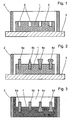
- FIG. 1 shows a schematic sectional view of a carrier plate model 1 inserted in a box 2.
- the carrier plate model 1 and the box 2 are arranged on a model plate 3.
- the carrier plate model 1 has on the upwardly facing side surface 5 a plurality of recesses 4.
- the recesses 4 may be evenly distributed over the side surface 5, but they may be arranged distributed differently densely in different sub-areas, the density of local braking forces may be dependent on braking.
- the recesses 4 are preferably holes of the same diameter (simple production). Alternatively, the recesses 4 in different areas of the side surface 5 may have different diameters.
- Figure 2 shows a schematic sectional view of the inserted into the box 2 support plate model 1 with introduced pins 6a-6d.
- the sections of the pins 6a-6d projecting from the carrier plate model 1 can be designed differently.
- the pins inserted in the recesses 4 are preferably of the same shape and size.
- the pins may be formed as a circular cylinder 6a or as to the end of the protruding from the support plate model 1 section tapered cylinder 6d.
- sections of the pins may have undercuts or may be at least partially formed club-shaped, as indicated at the pins 6c and 6d.
- the dipping into the support plate model 1 sections of the pins 6a-6d may be formed in a cylindrical shape with a smooth wall.
- these sections preferably have a contouring, d. H.
- d. H For example, circumferential grooves or a circumferential thread, as indicated at pin 6c.
- a molding compound 7 is applied to the carrier plate model 1. Subsequently, the applied Compress molding compound 7 and / or cured. This can be done for example by applying pressure to the molding compound. Moreover, it is possible to densify and / or cure the molding compound 7 by shaking and / or heating.
- the molding compound 7 After compaction and / or hardening of the molding compound 7, it is rotated by 180 ° with the box 2 and the carrier plate model 1 along the longitudinal axis of the model. Subsequently, the support plate model 1 is removed from the molding compound 7 such that the protruding in Figure 2 from the support plate model 1 sections of the pins 6a-6d remain in the molding compound 7. After removing the support plate model from the molding compound 7, this is covered with a second, pre-pressed and / or cured molding compound. The molding compound 7 and the second molding compound form a Suplatteng beauhohlraum 8.
- the second molding compound 7 has at least one riser and a sprue.
- the melt is now allowed to solidify such that a cast iron support plate, preferably a cast iron carrier plate with vermiculargraphite forms.
- a cast iron support plate preferably a cast iron carrier plate with vermiculargraphite forms.
- the cast iron support plate is removed from the mold. Steiger and sprue are separated from the cast iron support plate and still adhering molding compound is removed, for example by a sandblast.
- a covering of the molding compound 7 by a second mold can be omitted.
- the melt is then metered into the molding compound 7 poured.
Landscapes
- Engineering & Computer Science (AREA)
- General Engineering & Computer Science (AREA)
- Mechanical Engineering (AREA)
- Braking Arrangements (AREA)
- Casting Or Compression Moulding Of Plastics Or The Like (AREA)
- Moulds For Moulding Plastics Or The Like (AREA)
- Moulding By Coating Moulds (AREA)
- Mounting, Exchange, And Manufacturing Of Dies (AREA)
Abstract
Description
Die Erfindung betrifft ein Verfahren zum Herstellen einer Belagträgerplatte. Ferner betrifft die Erfindung eine Belagträgerplatte mit einer Metallguß-Grundplatte mit einer Trägerfläche zur Aufnahme einer Reibbelagmasse, wobei aus der Trägerfläche Halteelemente hervorstehen.The invention relates to a method for producing a lining carrier plate. Furthermore, the invention relates to a lining carrier plate with a metal casting base plate having a support surface for receiving a Reibbelagsasse, wherein protrude from the support surface holding elements.
Brems- bzw. Kupplungsbeläge bestehen üblicherweise aus einer Trägerplatte mit einer aufgepreßten Reibbelagmasse. Zur Verbesserung der Haftung zwischen der Trägerplatte und der Reibbelagmasse wird vielfach vor dem Aufpressen der Reibbelagmasse ein Kleber auf die Trägerplatte aufgetragen. Bei diesem Kleber handelt es sich in der Regel um einen Kleber auf einer Phenolharzbasis. Ggf. kann zwischen dem Kleber und der Reibbelagmasse noch eine Underlayer-Masse angeordnet werden, die beim Bremsvorgang auftretende Schwingungen dämpft. Die Trägerplatte besteht bei derartigen Brems- bzw. Kupplungsbelägen aus Stahl. Nachteilig bei dem üblichen Aufbau eines Brems- bzw. Kupplungsbelags ist zum einen, dass der Kleber oftmals den beim Bremsen in dem Reibbelag auftretenden hohen Temperaturen und Scherkräften nicht standhält. Dies führt unter Umständen zu einer Ablösung der Reibbelagmasse von der Trägerplatte und damit zu einer Zerstörung des Brems- bzw. Kupplungsbelags. Zum anderen ist das Gewicht einer derartigen Anordnung aufgrund des bei der Herstellung der Trägerplatte verwendeten Stahls recht hoch.Brake or clutch linings usually consist of a carrier plate with a pressed friction lining. To improve the adhesion between the support plate and the Reibbelagmasse an adhesive is often applied to the support plate before pressing the Reibbelagmasse. This adhesive is usually a phenolic resin based adhesive. Possibly. it is also possible to arrange an underlayer mass between the adhesive and the friction lining mass, which dampens vibrations occurring during the braking process. The support plate is in such brake or clutch linings made of steel. A disadvantage of the usual construction of a brake or clutch lining is, on the one hand, that the adhesive often does not withstand the high temperatures and shear forces occurring during braking in the friction lining. Under certain circumstances, this leads to a separation of the Reibbelagmasse from the support plate and thus to a destruction of the brake or clutch lining. On the other hand, the weight of such an arrangement is quite high due to the steel used in the manufacture of the support plate.
Um das Problem des den hohen Temperaturen und Scherkräften nicht standhaltenden Klebers zu lösen, sind Reibbeläge entwikkelt worden, bei denen die Verbindung zwischen der Trägerplatte und der Reibbelagmasse verbessert wurde. So können beispielsweise Löcher in die Trägerplatte eingebracht werden. Diese können beim Verpressen mit Reibbelagmasse gefüllt werden. So wird eine den Scherkräften besser standhaltende Verbindung zwischen der Reibbelagmasse und der Trägerplatte erzeugt. Beispielsweise ist es bekannt, in der dem Reibbelag zugewandten Fläche der Trägerplatte durch Laserstrahlen eine Mehrzahl von Vertiefungen einzubringen, wobei ein Teil des aus den Vertiefungen entfernten Materials am Rand dieser aufgeworfen wird.In order to solve the problem of the adhesive which does not withstand the high temperatures and shear forces, friction linings have been developed in which the connection between the carrier plate and the friction lining mass has been improved. For example, holes can be made in the carrier plate. These can be filled with friction lining during pressing. In this way, a connection between the friction lining mass and the carrier plate, which holds the shear forces better, is produced. For example, it is known to introduce a plurality of depressions in the surface of the carrier plate facing the friction lining by laser beams, whereby a portion of the material removed from the depressions is thrown up at the edge thereof.
Darüber hinaus ist es bekannt, Halteelemente auf der der Reibbelagmasse zugewandten Seite der Trägerplatte zu erzeugen. Dies kann geschehen, indem die Halteelemente entweder aus dem Trägerplattenmaterial herausgearbeitet werden, beispielsweise in Form einer Einkerbung und/oder einer Spananhebung, oder indem die Halteelemente auf die Trägerplatte aufgebracht werden, beispielsweise in der Form von aufgeschweißten oder aufgesinterten Gittern oder Stiften.In addition, it is known to produce holding elements on the Reibbelagmasse side facing the carrier plate. This can be done by the holding elements are machined either from the backing plate material, for example in the form of a notch and / or a chip lift, or by the holding elements are applied to the carrier plate, for example in the form of welded or sintered grids or pins.
Die oben genannten Verfahren zur Verbesserung der Verbindung zwischen der Trägerplatte und der Reibbelagmasse sind jedoch nicht geeignet, das Gewicht eines Reibbelags zu reduzieren, da alle Verfahren auf einer Trägerplatte aus Stahl basieren.However, the above methods for improving the connection between the carrier plate and the Reibbelagmasse are not suitable to reduce the weight of a friction lining, since all methods are based on a support plate made of steel.
Aufgabe der vorliegenden Erfindung ist es, gewichtsreduzierte Reibbeläge mit einer verbesserten Verbindung zwischen einer Reibbelagmasse und einer Belagträgerplatte bereitzustellen.The object of the present invention is to provide weight-reduced friction linings with an improved connection between a friction lining mass and a lining carrier plate.
Diese Aufgabe wird erfindungsgemäß durch ein Verfahren zum Herstellen einer Belagträgerplatte mit den Merkmalen des Anspruchs 1 bzw. durch eine Belagträgerplatte mit den Merkmalen des Anspruchs 5 bzw. durch ein Verfahren zum Herstellen eines Reibbelags mit den Merkmalen des Anspruchs 9 bzw. durch einen Reibbelag mit den Merkmalen des Anspruchs 10 gelöst.This object is achieved by a method for producing a lining carrier plate with the features of
Eine Belagträgerplatte wird erfindungsgemäß hergestellt, indem
- a) ein Trägerplattenmodell bereitgestellt wird, wobei das Trägerplattenmodell an einer Seitenfläche, die der einem Reibbelag zugewandten Fläche der Trägerplatte entspricht, mehrere Ausnehmungen aufweist, in welche jeweils ein Stift derart eingebracht wird, daß der Stift zum Teil aus dem Trägerplattenmodell herausragt;
- b) das Trägerplattenmodell und die aus dem Modell herausragenden Abschnitte der Stifte von einer Formmasse umschlossen werden,
die Formmasse verdichtet und/oder gehärtet wird,
das Trägerplattenmodell aus der gehärteten und/oder verdichteten Formmasse derart entnommen wird, daß die Stifte mit den aus dem Trägerplattenmodell herausragenden Abschnitten in der Formmasse verbleiben und ein Trägerplattengießhohlraum gebildet wird, in welchen die Stifte hineinragen; - c) eine Schmelze in den Trägerplattengießhohlraum gegossen wird, wobei die in den Trägerplattengießhohlraum hineinragenden Abschnitte der Stifte von der Schmelze umschlossen werden;
- d) die Schmelze derart erstarren gelassen wird, daß eine Eisenguß-Belagträgerplatte gebildet wird; und
- e) die Belagträgerplatte aus der Form entnommen wird.
- a) a carrier plate model is provided, wherein the carrier plate model on a side surface corresponding to the friction lining facing surface of the carrier plate having a plurality of recesses, in each of which a pin is inserted so that the pin protrudes partially from the carrier plate model;
- b) the carrier plate model and the protruding from the model portions of the pins are enclosed by a molding compound,
the molding compound is compacted and / or hardened,
the carrier plate model of the cured and / or compacted molding material is removed such that the pins remain in the molding compound with the sections projecting from the carrier plate model and a carrier plate casting cavity is formed, into which the pins project; - c) casting a melt into the carrier plate casting cavity, the portions of the pins projecting into the carrier plate casting cavity being enclosed by the melt;
- d) allowing the melt to solidify to form a cast iron backing plate; and
- e) the lining carrier plate is removed from the mold.
Unter einem Stift soll hier jeglicher Körper verstanden werden, der sich über eine gegebene Länge derart erstreckt, daß er über einen Teil dieser Länge in einer Ausnehmung des Belagträgerplattenmödells lösbar einbringbar ist, beispielsweise ein beliebiger zumindest teilweise zylindrisch- oder kegelförmig geformter Körper.Under a pin here any body to be understood, which extends over a given length such that it is releasably insertable over a portion of this length in a recess of the Belagträgerplattenmödells, for example, any at least partially cylindrical or conically shaped body.
Durch die Verwendung einer Schmelze, die zu einer Eisenguß-Trägerplatte erstarrt, wird eine Gewichtsreduzierung der Belagträgerplatte erreicht. Dies ist ein zunehmend wichtiger Aspekt zur Herstellung von Reibbelägen, da die Automobilindustrie bemüht ist, das gesamte Gewicht ihrer Fahrzeuge zu verringern, um deren Kraftstoffverbrauch zu senken. Ferner bedingt die Gewichtsreduzierung der Belagträgerplatte eine Verminderung der Transportkosten.By using a melt that solidifies into a cast iron support plate, a weight reduction of the lining carrier plate is achieved. This is an increasingly important aspect of producing friction linings as the automotive industry strives to reduce the overall weight of their vehicles to reduce their fuel consumption. Furthermore, the weight reduction of the lining carrier plate causes a reduction in transport costs.
Das Einbringen von Stiften bietet gegenüber einem Erzeugen von hervorspringenden Halteelementen aus dem Gußmaterial selbst (zum Beispiel durch Ausnehmungen in einer Formmasse aufgrund von Vorsprüngen eines Trägerplattenmodells, wie z.B. aus GB 2 303 891 bekannt) beim Gießen den Vorteil, daß das Material der eingegossenen Stifte so gewählt sein kann, daß die Stifte nicht abgeschert werden können und besser in der Belagträgerplatte verankert sind.The introduction of pins offers the advantage over pouring protruding support members from the cast material itself (for example, through recesses in a molding compound due to protrusions of a support plate model, such as
Das Einbringen der Stifte durch Umgießen vermeidet ferner Bearbeitungsschritte an der erkalteten Guß-Belagträgerplatte zur Schaffung von Halteelementen. Diese Bearbeitungsschritte erfordern einerseits zusätzliche Bearbeitungszeit und -kosten und gestalten sich andererseits bei Gußmaterialien schwieriger als bei Stahl.The introduction of the pins by encapsulation further avoids processing steps on the cooled cast pad carrier plate to create holding elements. On the one hand, these processing steps require additional processing time and costs and, on the other hand, are more difficult with cast materials than with steel.
Bei dem oben genannten Verfahren können die Ausnehmungen in dem Trägerplattenmodell mit einer Vielzahl unterschiedlicher Stifte versehen werden. So ist es möglich, die Art der Stifte, die in das Trägerplattenmodell eingebracht werden, innerhalb der mit den Ausnehmungen versehenen Fläche des Trägerplattenmodells zu variieren, um die Art und/oder Stärke der Verankerung in unterschiedlichen Bereichen der Trägerplatte zu steuern. Beispielsweise kann man in den Bereichen der Trägerplatte, die beim Bremsen besonders hohen Scherkräften unterworfen sind, Stifte mit besonders guten Verankerungseigenschaften zwischen Trägerplatte und Reibbelagmasse verwenden.In the above method, the recesses in the carrier plate model can be provided with a plurality of different pins. Thus, it is possible to vary the type of pins that are inserted into the carrier plate model within the recessed surface of the carrier plate model to control the type and / or strength of the anchoring in different areas of the carrier plate. For example, you can in the areas of the support plate, which are subjected to particularly high shear forces during braking, use pins with particularly good anchoring properties between the support plate and Reibbelagmasse.
Vorteilhafterweise sind die in das Trägerplattenmodell eingebrachten Stifte derart ausgebildet, daß die aus dem Modell herausragenden Abschnitte der Stifte wenigstens einen sich zur Belagträgerfläche hin verjüngenden Abschnitt, d. h. wenigstens eine Hinterschneidung, aufweisen. Beim Verpressen der Reibbelagmasse mit den Hinterschneidungen aufweisenden Stiften wird so eine formschlüssige Verbindung zwischen der Reibbelagmasse und den Stiften der Trägerplatte geschaffen, die besonders zur Aufnahme der beim Bremsvorgang auftretenden Scherkräfte geeignet ist. Zusätzlich ist es möglich, die Anzahl und die Form der Hinterschneidungen aufweisenden Stifte an die in unterschiedlichen Bereichen der Trägerplatte herrschenden Scherkräfte anzupassen.Advantageously, the pins introduced into the carrier plate model are designed such that the portions of the pins projecting out of the model have at least one section tapering towards the carrier carrier surface, ie. H. at least one undercut. When pressing the friction lining with the undercuts having pins so a positive connection between the Reibbelagsasse and the pins of the support plate is created, which is particularly suitable for receiving the shear forces occurring during the braking process. In addition, it is possible to adapt the number and the shape of the undercuts having pins to the shear forces prevailing in different areas of the carrier plate.
Besonders vorteilhaft ist es, wenn die in die Ausnehmungen des Trägerplattenmodells eingebrachten Abschnitte der Stifte zumindest teilweise eine Konturierung aufweisen, welche derart ausgebildet ist, daß die Stifte lösbar in das Trägerplattenmodell einbringbar sind. Unter einer Konturierung soll hier jede von einer glattwandigen zylinder- oder kegelförmigen Stiftform abweichende Oberflächengestaltung der Stiftabschnitte verstanden werden. Beispielsweise sind die Abschnitte der Stifte mit Nuten oder einem Gewinde versehen. Beim Eingießen der Schmelze in den Trägerplattengießhohlraum werden diese in den Trägerplattengießhohlraum hineinragenden Abschnitte der Stifte von der Schmelze umschlossen. Dadurch wird eine besonders gute Verankerung der Stifte in der Trägerplatte erreicht.It is particularly advantageous if the sections of the pins introduced into the recesses of the carrier plate model at least partially have a contouring which is designed in such a way that the pins are releasably insertable into the carrier plate model. Under a contouring here is intended to deviate from a smooth-walled cylindrical or conical pin shape surface design of the pin sections be understood. For example, the portions of the pins are grooved or threaded. As the melt is poured into the backing slab casting cavity, these portions of the pins projecting into the backing slab casting cavity are enclosed by the melt. As a result, a particularly good anchoring of the pins in the carrier plate is achieved.
Bei dem erfindungsgemäßen Verfahren ist es vorteilhaft, daß die Schmelze beim Erstarren einen Eisenguß mit Vermiculargraphit bildet. Die physikalischen Eigenschaften von Gußeisen mit Vermiculargraphit liegen zwischen denen eines Gußeisens mit Kugelgraphit und denen eines Gußeisens mit Lamellengraphit. Vorteilhafterweise ist einerseits die Festigkeit und Zähigkeit des Gußeisens mit Vermiculargraphit höher als bei Gußeisen mit Lamellengraphit und zum anderen die Schwingungsdämpfung besser als bei Gußeisen mit Kugelgraphit.In the method according to the invention, it is advantageous that the melt forms a cast iron with vermicular graphite during solidification. The physical properties of vermicular graphite cast iron are between those of nodular cast iron and those of cast iron with lamellar graphite. Advantageously, on the one hand the strength and toughness of the cast iron with vermicular graphite is higher than cast iron with flake graphite and on the other hand, the vibration damping better than cast iron with nodular graphite.
Zur Lösung der eingangs genannten Aufgabe wird ferner eine Belagträgerplatte mit einer Metallguß-Grundplatte mit einer Trägerfläche zur Aufnahme einer Reibbelagmasse, wobei aus der Trägerfläche Halteelemente hervorstehen und die Grundplatte aus Eisenguß hergestellt ist, vorgeschlagen, die dadurch gekennzeichnet ist, daß die Halteelemente Stifte sind, die in die Grundplatte bei deren Herstellung derart eingegossen werden, daß jeweils ein Abschnitt der Stifte aus der Trägerfläche der Grundplatte herausragt.To solve the aforementioned object, a lining carrier plate with a metal casting base plate is further provided with a support surface for receiving a Reibbelagsasse, protruding from the support surface holding elements and the base plate is made of cast iron, proposed, which is characterized in that the holding elements are pins, which are cast in the base plate during their manufacture such that in each case a portion of the pins protrudes from the support surface of the base plate.
Weitere vorteilhafte und/oder bevorzugte Weiterbildungen der Erfindung sind in den Unteransprüchen gekennzeichnet.Further advantageous and / or preferred developments of the invention are characterized in the subclaims.
Im folgenden wird die Erfindung anhand einer in der Zeichnung dargestellten bevorzugten Ausführungsform näher beschrieben. In der Zeichnung zeigt:
Figur 1 eine schematische Schnittansicht eines in einen Kasten eingelegten Trägerplattenmodells,Figur 2 eine schematische Schnittansicht eines in einen Kasten eingelegten Trägerplattenmodells mit in dem Trägerplattenmodell eingebrachten Stiften, undFigur 3 eine schematische Schnittansicht einer verdichteten und/oder gehärteten Formmasse mit in dieser angeordneten Stiften.
- FIG. 1 shows a schematic sectional view of a carrier plate model inserted in a box,
- Figure 2 is a schematic sectional view of an inserted into a box carrier plate model with introduced in the carrier plate model pins, and
- Figure 3 is a schematic sectional view of a compacted and / or cured molding compound arranged in this pins.
Figur 1 zeigt eine schematische Schnittansicht eines in einen Kasten 2 eingelegten Trägerplattenmodells 1. Das Trägerplattenmodell 1 und der Kasten 2 sind auf einer Modellplatte 3 angeordnet. Das Trägerplattenmodell 1 weist an der nach oben weisenden Seitenfläche 5 mehrere Ausnehmungen 4 auf. Die Ausnehmungen 4 können gleichmäßig über die Seitenfläche 5 verteilt sein, sie können jedoch auch in unterschiedlichen Teilbereichen unterschiedlich dicht verteilt angeordnet sein, wobei die Dichte von beim Bremsen örtlich wirkenden Scherkräften abhängig sein kann. Die Ausnehmungen 4 sind vorzugsweise Bohrungen gleichen Durchmessers (einfache Herstellung). Alternativ können die Ausnehmungen 4 in unterschiedlichen Bereichen der Seitenfläche 5 unterschiedliche Durchmesser aufweisen.FIG. 1 shows a schematic sectional view of a
Figur 2 zeigt eine schematische Schnittansicht des in den Kasten 2 eingelegten Trägerplattenmodells 1 mit eingebrachten Stiften 6a-6d. Wie es schematisch in Figur 2 angedeutet ist, können die aus dem Trägerplattenmodell 1 herausragenden Abschnitte der Stifte 6a-6d unterschiedlich ausgebildet sein. Aus Gründen einfacher Herstellung sind die in den Ausnehmungen 4 eingebrachten Stifte jedoch vorzugsweise von gleicher Form und Größe. Die Stifte können als Kreiszylinder 6a oder als sich zum Ende des aus dem Trägerplattenmodells 1 ragenden Abschnitts verjüngende Zylinder 6d ausgebildet sein. Zur besseren Verankerung der Stifte 6a-6d in einer Reibbelagmasse können die aus dem Trägerplattenmodell 1 ragenden Abschnitte der Stifte Hinterschneidungen aufweisen oder können zumindest teilweise keulenförmig ausgebildet sein, wie dies bei den Stiften 6c und 6d angedeutet ist. Die in das Trägerplattenmodell 1 eintauchenden Abschnitte der Stifte 6a-6d können zylinderförmig mit glatter Wandung ausgebildet sein. Zur Herstellung einer besseren Verankerung im Guß weisen diese Abschnitte jedoch vorzugsweise eine Konturierung, d. h. beispielweise umlaufende Nuten oder ein umlaufendes Gewinde, auf, wie dies bei Stift 6c angedeutet ist.Figure 2 shows a schematic sectional view of the inserted into the
Nachdem das Trägerplattenmodell 1 mit einer Mehrzahl von Stiften 6a-6d versehen wurde, wird eine Formmasse 7 auf das Trägerplattenmodell 1 aufgebracht. Anschließend wird die aufgebrachte Formmasse 7 verdichtet und/oder gehärtet. Dies kann beispielsweise durch Aufbringen von Druck auf die Formmasse erfolgen. Darüber hinaus ist es möglich, die Formmasse 7 durch Rütteln und/oder Erhitzen zu verdichten und/oder zu härten.After the
Nach dem Verdichten und/oder Härten der Formmasse 7 wird diese mit dem Kasten 2 und dem Trägerplattenmodell 1 entlang der Längsachse des Modells um 180° gedreht. Anschließend wird das Trägerplattenmodell 1 derart aus der Formmasse 7 entnommen, daß die in Figur 2 aus dem Trägerplattenmodell 1 herausragenden Abschnitte der Stifte 6a-6d in der Formmasse 7 verbleiben. Nach dem Entnehmen des Trägerplattenmodells aus der Formmasse 7 wird diese mit einer zweiten, vorgepreßten und/oder gehärteten Formmasse abgedeckt. Die Formmasse 7 und die zweite Formmasse bilden einen Trägerplattengießhohlraum 8. Die zweite Formmasse 7 weist zumindest einen Steiger und einen Einguß auf. In dem von der Formmasse 7 und der zweiten Formmasse gebildeten Trägerplattengießhohlraum 8 wird über den Einguß eine Schmelze eingegossen, wobei die in den Trägerplattenhohlraum 8 hineinragende Abschnitte der Stifte 6a-6d von der Schmelze umschlossen werden. In dem Trägerplattenhohlraum 8 befindliche und/oder bei dem Schmelzvorgang entstehende Gase können durch den Steiger entweichen.After compaction and / or hardening of the
In dem Trägerplattengießhohlraum wird die Schmelze nun derart erstarren gelassen, daß sich eine Eisenguß-Trägerplatte, vorzugsweise eine Eisenguß-Trägerplatte mit Vermiculargraphit, bildet. Nach dem Erstarren der Schmelze wird die Eisenguß-Trägerplatte aus der Gußform herausgelöst. Steiger und Einguß werden von der Eisenguß-Trägerplatte getrennt und noch anhaftende Formmasse wird beispielsweise durch ein Sandstrahlgebläse entfernt.In the Trägerplattengießhohlraum the melt is now allowed to solidify such that a cast iron support plate, preferably a cast iron carrier plate with vermiculargraphite forms. After solidification of the melt, the cast iron support plate is removed from the mold. Steiger and sprue are separated from the cast iron support plate and still adhering molding compound is removed, for example by a sandblast.
Im Rahmen des Erfindungsgedankens sind zahlreiche alternative Ausführungsformen denkbar. Beispielsweise kann ein Abdecken der Formmasse 7 durch eine zweite Form unterbleiben. Die Schmelze wird dann dosiert in die Formmasse 7 eingegossen. Eine Formgebung der nach oben nicht begrenzten Schmelze erfolgt durch die Schwerkraft.Numerous alternative embodiments are conceivable within the scope of the inventive concept. For example, a covering of the
Claims (10)
- Method of producing a lining support plate in which:a) a support plate pattern (1) is prepared, whereby the support plate pattern (1) has on one lateral face (5) which corresponds to the face of the support plate facing a friction lining a plurality of recesses (6) into each of which a pin (6a - 6d) is introduced in such a way that the pin (6a - 6d) partially projects out of the support plate pattern (1);b) the support plate pattern (1) and the portions of the pins (6a - 6d) projecting out of the support plate pattern (1) are surrounded by a moulding compound (7),
the moulding compound (7) is compressed and/or cured,
the support plate pattern (1) is removed from the cured and/or compressed moulding compound (7) in such a way that the pins (6a - 6d) with the portions projecting out of the support plate pattern (1) remain in the moulding compound (7) and a support plate casting cavity (8) is formed into which the pins (a - 6d) protrude;c) a melt is poured into the support plate casting cavity (8), whereby the portions of the pins (6a - 6d) protruding into the support plate casting cavity (8) are surrounded by the melt;d) the melt is left to solidify in such a way that a cast iron lining support plate is formed; ande) the lining support plate is removed from the mould. - Method as claimed in Claim 1, wherein the pins (6a - 6d) introduced into the support plate pattern (1) are constructed in such a way that the portions of the pins (6a - 6d) projecting out of the support plate pattern (1) have undercuts.
- Method as claimed in any one of Claims 1 or 2, wherein the portions of the pins (6a - 6d) introduced into the recesses in the support plate pattern (1) are contoured.
- Method as claimed in any one of Claims 1 to 3, characterised in that when the melt solidifies it forms a cast iron with vermicular graphite.
- Lining support plate with a cast metal base plate with a support surface to receive a friction lining material, wherein retaining elements project out of the support surface and wherein the base plate is made from cast iron, characterised in that the retaining elements are pins (6a - 6d) which are cast into the base plate during production thereof in such a way that in each case a portion of the pins (6a - 6d) projects out of the support surface of the base plate.
- Lining support plate as claimed in Claim 5, characterised in that the base plate is produced from cast iron with vermicular graphite.
- Lining support plate as claimed in Claim 5 or 6, characterised in that the pins (6a - 6d) are constructed in such a way that the portions of the pins (6a - 6d) projecting out of the base plate have undercuts.
- Lining support plate as claimed in any one of Claims 5 to 7, characterised in that a portion of the pins (6a - 6d) cast into the base plate during production thereof is contoured.
- Method of producing a friction lining, in which a lining support plate is produced according to a method as claimed in any one of Claims 1 to 4, and a friction lining material with an organic binder is pressed onto the lateral surface (5) of the lining support plate having the pins (6a - 6d).
- Friction lining with a lining support plate as claimed in any one of Claims 5 to 8 and a friction lining material, wherein a friction lining with an organic binder is pressed onto the support surface.
Applications Claiming Priority (3)
| Application Number | Priority Date | Filing Date | Title |
|---|---|---|---|
| DE10350725A DE10350725B4 (en) | 2003-10-30 | 2003-10-30 | Pad carrier plate and method for its production |
| DE10350725 | 2003-10-30 | ||
| PCT/EP2004/011915 WO2005042999A1 (en) | 2003-10-30 | 2004-10-21 | Lining support plate and associated production method |
Publications (2)
| Publication Number | Publication Date |
|---|---|
| EP1599682A1 EP1599682A1 (en) | 2005-11-30 |
| EP1599682B1 true EP1599682B1 (en) | 2006-09-27 |
Family
ID=34529930
Family Applications (1)
| Application Number | Title | Priority Date | Filing Date |
|---|---|---|---|
| EP04790720A Expired - Lifetime EP1599682B1 (en) | 2003-10-30 | 2004-10-21 | Lining support plate and associated production method |
Country Status (8)
| Country | Link |
|---|---|
| US (1) | US7810546B2 (en) |
| EP (1) | EP1599682B1 (en) |
| JP (1) | JP2007510108A (en) |
| KR (1) | KR100806481B1 (en) |
| AT (1) | ATE340950T1 (en) |
| BR (1) | BRPI0416066A (en) |
| DE (2) | DE10350725B4 (en) |
| WO (1) | WO2005042999A1 (en) |
Families Citing this family (8)
| Publication number | Priority date | Publication date | Assignee | Title |
|---|---|---|---|---|
| DE102008014550B4 (en) * | 2008-03-15 | 2011-12-15 | Meteor Umformtechnik Gmbh & Co. Kg | Support plate for brake linings of vehicles |
| DE202009017931U1 (en) | 2009-03-03 | 2011-01-20 | Stanz- Und Umformtechnik Jancer Gmbh | Brake pad support retaining plate |
| DE102010031889A1 (en) | 2010-07-21 | 2012-01-26 | Jancer Vermögensverwaltungs Ug (Haftungsbeschränkt) & Co. Kg | Method for producing a brake pad carrier |
| DE102012103196B4 (en) | 2012-03-26 | 2023-08-24 | ABC Advanced Brake Components | Brake pad backing plate and method of manufacturing a brake pad backing plate |
| CN107096904B (en) * | 2017-05-19 | 2019-04-26 | 扬州电力设备修造厂有限公司 | A method of producing wear-resisting composite liner |
| DE102017209116A1 (en) * | 2017-05-31 | 2018-12-06 | Robert Bosch Gmbh | Brake pad assembly, method |
| DE102020106296A1 (en) | 2020-03-09 | 2021-09-23 | Tmd Friction Services Gmbh | Lining carrier plate for a disc brake of a motor vehicle and a method for its production |
| GB2643107A (en) * | 2024-07-26 | 2026-02-11 | Tribol Braking Ltd | A backing plate mould |
Family Cites Families (10)
| Publication number | Priority date | Publication date | Assignee | Title |
|---|---|---|---|---|
| JPS5928786B2 (en) * | 1976-10-29 | 1984-07-16 | トヨタ自動車株式会社 | disc brake pad |
| US4799579A (en) * | 1985-11-18 | 1989-01-24 | Myers Paul A | Clutch and brake friction assembly and method of making same |
| JPH0617700B2 (en) * | 1990-11-07 | 1994-03-09 | 川崎重工業株式会社 | Brake disc material |
| JPH068138U (en) * | 1992-07-09 | 1994-02-01 | 曙ブレーキ工業株式会社 | Railway brake shoe |
| GB9506032D0 (en) * | 1995-03-24 | 1995-05-10 | T & N Technology Ltd | Backplate for friction material |
| GB9515926D0 (en) * | 1995-08-03 | 1995-10-04 | T & N Technology Ltd | Manufacture of brake pads |
| DE19532019C1 (en) | 1995-08-31 | 1997-02-13 | Ae Goetze Gmbh | Carrier plate for friction linings |
| JPH09111393A (en) * | 1995-10-20 | 1997-04-28 | Hitachi Metals Ltd | Disk brake rotor material |
| JPH11230208A (en) * | 1998-02-17 | 1999-08-27 | Hitachi Chem Co Ltd | Back metal for disk brake pad and manufacture thereof, and disk brake pad using the disc brake pad |
| DE29804619U1 (en) * | 1998-03-10 | 1998-06-04 | Obtec A/S, Svendborg | Brake shoe for disc brakes |
-
2003
- 2003-10-30 DE DE10350725A patent/DE10350725B4/en not_active Expired - Fee Related
-
2004
- 2004-10-21 JP JP2006537138A patent/JP2007510108A/en active Pending
- 2004-10-21 DE DE502004001606T patent/DE502004001606D1/en not_active Expired - Lifetime
- 2004-10-21 EP EP04790720A patent/EP1599682B1/en not_active Expired - Lifetime
- 2004-10-21 WO PCT/EP2004/011915 patent/WO2005042999A1/en not_active Ceased
- 2004-10-21 KR KR1020067008441A patent/KR100806481B1/en not_active Expired - Fee Related
- 2004-10-21 AT AT04790720T patent/ATE340950T1/en not_active IP Right Cessation
- 2004-10-21 BR BRPI0416066-5A patent/BRPI0416066A/en not_active IP Right Cessation
- 2004-10-21 US US10/577,248 patent/US7810546B2/en not_active Expired - Fee Related
Also Published As
| Publication number | Publication date |
|---|---|
| US7810546B2 (en) | 2010-10-12 |
| EP1599682A1 (en) | 2005-11-30 |
| WO2005042999A1 (en) | 2005-05-12 |
| ATE340950T1 (en) | 2006-10-15 |
| BRPI0416066A (en) | 2008-03-04 |
| DE10350725A1 (en) | 2005-06-09 |
| KR100806481B1 (en) | 2008-02-21 |
| DE502004001606D1 (en) | 2006-11-09 |
| KR20060093340A (en) | 2006-08-24 |
| DE10350725B4 (en) | 2006-10-12 |
| US20070215305A1 (en) | 2007-09-20 |
| JP2007510108A (en) | 2007-04-19 |
Similar Documents
| Publication | Publication Date | Title |
|---|---|---|
| DE69602602T2 (en) | MANUFACTURING BRAKE PADS | |
| EP1211231B1 (en) | Method of making a friction body of silicon infiltrated carbon fiber reinforced porous carbon and use of such a friction body | |
| DE602004000859T2 (en) | IMPROVED FEEDING ELEMENT AND SYSTEM FOR METAL CASTING | |
| EP0777830B1 (en) | Disk brake calliper | |
| DE102008052697A1 (en) | Inserts with apertures for steamed products and methods of manufacture and use thereof | |
| DE19532019C1 (en) | Carrier plate for friction linings | |
| EP1599682B1 (en) | Lining support plate and associated production method | |
| DE4212558A1 (en) | REINFORCED LIGHT METAL PRODUCT AND METHOD FOR THE PRODUCTION THEREOF | |
| DE102007044744B4 (en) | Brake pad for rail vehicles | |
| DE102009034043B4 (en) | Friction dampened product | |
| DE1475351A1 (en) | One-piece unit of piston and brake pad for disc brakes | |
| DE69216018T2 (en) | Iron-based lining to be cast | |
| EP2252444B1 (en) | Device for the manufacture of friction surfaces | |
| EP1256741B1 (en) | Brake or clutch lining and method for its production | |
| DE2707901A1 (en) | Lightweight eccentric worm for pump - prepd. by casting mixt. of resin and wear and chemical resistant reinforcing filler | |
| DE202004021109U1 (en) | Feeder element for feeder system used in metal casting, includes first end for mounting on mold pattern, opposite second end for receiving feeder sleeve, and bore between the first and second ends defined by sidewall | |
| DE2916211A1 (en) | METHOD FOR PRODUCING A FIREPROOF FOUNDRY MOLD | |
| EP1900961A2 (en) | Brake disc and method for manufacturing the brake disc | |
| DE202009012778U1 (en) | Composite brake block sole and composite brake block | |
| DE102024002429A1 (en) | Method for pressing a threaded bushing into a metallic casting component and the metallic casting component | |
| DE102007037931A1 (en) | Producing mold part of cast mold for permanent mold casting, comprises producing mold base in surface region in relation to the contour of the cast part manufactured with the cast mold, and spraying plastic material on the surface region | |
| DE102019115587A1 (en) | Carrier plate with anchoring ribs, method for manufacturing a carrier plate | |
| DE102022003072A1 (en) | Process for the production of a sand core for use in casting molds | |
| DE1508612C (en) | Casting mold for casting a metal casting part | |
| DE102007062965A1 (en) | Producing cast core having cylinder liner to produce engine blocks made of cast metal, by bonding/adhering washable core material such as salt with surface of cylinder liner, and forming and sintering off core material on the liner surface |
Legal Events
| Date | Code | Title | Description |
|---|---|---|---|
| PUAI | Public reference made under article 153(3) epc to a published international application that has entered the european phase |
Free format text: ORIGINAL CODE: 0009012 |
|
| 17P | Request for examination filed |
Effective date: 20050422 |
|
| AK | Designated contracting states |
Kind code of ref document: A1 Designated state(s): AT BE BG CH CY CZ DE DK EE ES FI FR GB GR HU IE IT LI LU MC NL PL PT RO SE SI SK TR |
|
| AX | Request for extension of the european patent |
Extension state: AL HR LT LV MK |
|
| GRAP | Despatch of communication of intention to grant a patent |
Free format text: ORIGINAL CODE: EPIDOSNIGR1 |
|
| GRAS | Grant fee paid |
Free format text: ORIGINAL CODE: EPIDOSNIGR3 |
|
| GRAA | (expected) grant |
Free format text: ORIGINAL CODE: 0009210 |
|
| AK | Designated contracting states |
Kind code of ref document: B1 Designated state(s): AT BE BG CH CY CZ DE DK EE ES FI FR GB GR HU IE IT LI LU MC NL PL PT RO SE SI SK TR |
|
| DAX | Request for extension of the european patent (deleted) | ||
| PG25 | Lapsed in a contracting state [announced via postgrant information from national office to epo] |
Ref country code: IT Free format text: LAPSE BECAUSE OF FAILURE TO SUBMIT A TRANSLATION OF THE DESCRIPTION OR TO PAY THE FEE WITHIN THE PRESCRIBED TIME-LIMIT;WARNING: LAPSES OF ITALIAN PATENTS WITH EFFECTIVE DATE BEFORE 2007 MAY HAVE OCCURRED AT ANY TIME BEFORE 2007. THE CORRECT EFFECTIVE DATE MAY BE DIFFERENT FROM THE ONE RECORDED. Effective date: 20060927 Ref country code: PL Free format text: LAPSE BECAUSE OF FAILURE TO SUBMIT A TRANSLATION OF THE DESCRIPTION OR TO PAY THE FEE WITHIN THE PRESCRIBED TIME-LIMIT Effective date: 20060927 Ref country code: NL Free format text: LAPSE BECAUSE OF FAILURE TO SUBMIT A TRANSLATION OF THE DESCRIPTION OR TO PAY THE FEE WITHIN THE PRESCRIBED TIME-LIMIT Effective date: 20060927 Ref country code: SK Free format text: LAPSE BECAUSE OF FAILURE TO SUBMIT A TRANSLATION OF THE DESCRIPTION OR TO PAY THE FEE WITHIN THE PRESCRIBED TIME-LIMIT Effective date: 20060927 Ref country code: FI Free format text: LAPSE BECAUSE OF FAILURE TO SUBMIT A TRANSLATION OF THE DESCRIPTION OR TO PAY THE FEE WITHIN THE PRESCRIBED TIME-LIMIT Effective date: 20060927 Ref country code: IE Free format text: LAPSE BECAUSE OF FAILURE TO SUBMIT A TRANSLATION OF THE DESCRIPTION OR TO PAY THE FEE WITHIN THE PRESCRIBED TIME-LIMIT Effective date: 20060927 Ref country code: CZ Free format text: LAPSE BECAUSE OF FAILURE TO SUBMIT A TRANSLATION OF THE DESCRIPTION OR TO PAY THE FEE WITHIN THE PRESCRIBED TIME-LIMIT Effective date: 20060927 Ref country code: SI Free format text: LAPSE BECAUSE OF FAILURE TO SUBMIT A TRANSLATION OF THE DESCRIPTION OR TO PAY THE FEE WITHIN THE PRESCRIBED TIME-LIMIT Effective date: 20060927 Ref country code: RO Free format text: LAPSE BECAUSE OF FAILURE TO SUBMIT A TRANSLATION OF THE DESCRIPTION OR TO PAY THE FEE WITHIN THE PRESCRIBED TIME-LIMIT Effective date: 20060927 |
|
| REG | Reference to a national code |
Ref country code: GB Ref legal event code: FG4D Free format text: NOT ENGLISH |
|
| GBT | Gb: translation of ep patent filed (gb section 77(6)(a)/1977) |
Effective date: 20060927 |
|
| PG25 | Lapsed in a contracting state [announced via postgrant information from national office to epo] |
Ref country code: MC Free format text: LAPSE BECAUSE OF NON-PAYMENT OF DUE FEES Effective date: 20061031 |
|
| REG | Reference to a national code |
Ref country code: CH Ref legal event code: EP |
|
| REG | Reference to a national code |
Ref country code: IE Ref legal event code: FG4D Free format text: LANGUAGE OF EP DOCUMENT: GERMAN |
|
| REF | Corresponds to: |
Ref document number: 502004001606 Country of ref document: DE Date of ref document: 20061109 Kind code of ref document: P |
|
| PG25 | Lapsed in a contracting state [announced via postgrant information from national office to epo] |
Ref country code: BG Free format text: LAPSE BECAUSE OF FAILURE TO SUBMIT A TRANSLATION OF THE DESCRIPTION OR TO PAY THE FEE WITHIN THE PRESCRIBED TIME-LIMIT Effective date: 20061227 Ref country code: DK Free format text: LAPSE BECAUSE OF FAILURE TO SUBMIT A TRANSLATION OF THE DESCRIPTION OR TO PAY THE FEE WITHIN THE PRESCRIBED TIME-LIMIT Effective date: 20061227 Ref country code: SE Free format text: LAPSE BECAUSE OF FAILURE TO SUBMIT A TRANSLATION OF THE DESCRIPTION OR TO PAY THE FEE WITHIN THE PRESCRIBED TIME-LIMIT Effective date: 20061227 |
|
| PG25 | Lapsed in a contracting state [announced via postgrant information from national office to epo] |
Ref country code: ES Free format text: LAPSE BECAUSE OF FAILURE TO SUBMIT A TRANSLATION OF THE DESCRIPTION OR TO PAY THE FEE WITHIN THE PRESCRIBED TIME-LIMIT Effective date: 20070107 |
|
| ET | Fr: translation filed | ||
| NLV1 | Nl: lapsed or annulled due to failure to fulfill the requirements of art. 29p and 29m of the patents act | ||
| PG25 | Lapsed in a contracting state [announced via postgrant information from national office to epo] |
Ref country code: PT Free format text: LAPSE BECAUSE OF FAILURE TO SUBMIT A TRANSLATION OF THE DESCRIPTION OR TO PAY THE FEE WITHIN THE PRESCRIBED TIME-LIMIT Effective date: 20070313 |
|
| REG | Reference to a national code |
Ref country code: IE Ref legal event code: FD4D |
|
| PLBE | No opposition filed within time limit |
Free format text: ORIGINAL CODE: 0009261 |
|
| STAA | Information on the status of an ep patent application or granted ep patent |
Free format text: STATUS: NO OPPOSITION FILED WITHIN TIME LIMIT |
|
| 26N | No opposition filed |
Effective date: 20070628 |
|
| BERE | Be: lapsed |
Owner name: TMD FRICTION SERVICES G.M.B.H. Effective date: 20061031 |
|
| PG25 | Lapsed in a contracting state [announced via postgrant information from national office to epo] |
Ref country code: AT Free format text: LAPSE BECAUSE OF NON-PAYMENT OF DUE FEES Effective date: 20061021 |
|
| PG25 | Lapsed in a contracting state [announced via postgrant information from national office to epo] |
Ref country code: GR Free format text: LAPSE BECAUSE OF FAILURE TO SUBMIT A TRANSLATION OF THE DESCRIPTION OR TO PAY THE FEE WITHIN THE PRESCRIBED TIME-LIMIT Effective date: 20061228 |
|
| PG25 | Lapsed in a contracting state [announced via postgrant information from national office to epo] |
Ref country code: EE Free format text: LAPSE BECAUSE OF FAILURE TO SUBMIT A TRANSLATION OF THE DESCRIPTION OR TO PAY THE FEE WITHIN THE PRESCRIBED TIME-LIMIT Effective date: 20060927 |
|
| PG25 | Lapsed in a contracting state [announced via postgrant information from national office to epo] |
Ref country code: HU Free format text: LAPSE BECAUSE OF FAILURE TO SUBMIT A TRANSLATION OF THE DESCRIPTION OR TO PAY THE FEE WITHIN THE PRESCRIBED TIME-LIMIT Effective date: 20070328 Ref country code: LU Free format text: LAPSE BECAUSE OF NON-PAYMENT OF DUE FEES Effective date: 20061021 Ref country code: TR Free format text: LAPSE BECAUSE OF FAILURE TO SUBMIT A TRANSLATION OF THE DESCRIPTION OR TO PAY THE FEE WITHIN THE PRESCRIBED TIME-LIMIT Effective date: 20060927 |
|
| PG25 | Lapsed in a contracting state [announced via postgrant information from national office to epo] |
Ref country code: CY Free format text: LAPSE BECAUSE OF FAILURE TO SUBMIT A TRANSLATION OF THE DESCRIPTION OR TO PAY THE FEE WITHIN THE PRESCRIBED TIME-LIMIT Effective date: 20060927 |
|
| REG | Reference to a national code |
Ref country code: CH Ref legal event code: PL |
|
| PG25 | Lapsed in a contracting state [announced via postgrant information from national office to epo] |
Ref country code: BE Free format text: LAPSE BECAUSE OF FAILURE TO SUBMIT A TRANSLATION OF THE DESCRIPTION OR TO PAY THE FEE WITHIN THE PRESCRIBED TIME-LIMIT Effective date: 20061031 |
|
| PG25 | Lapsed in a contracting state [announced via postgrant information from national office to epo] |
Ref country code: LI Free format text: LAPSE BECAUSE OF NON-PAYMENT OF DUE FEES Effective date: 20081031 Ref country code: CH Free format text: LAPSE BECAUSE OF NON-PAYMENT OF DUE FEES Effective date: 20081031 |
|
| PGFP | Annual fee paid to national office [announced via postgrant information from national office to epo] |
Ref country code: DE Payment date: 20131031 Year of fee payment: 10 Ref country code: FR Payment date: 20131022 Year of fee payment: 10 Ref country code: GB Payment date: 20131021 Year of fee payment: 10 |
|
| PGFP | Annual fee paid to national office [announced via postgrant information from national office to epo] |
Ref country code: IT Payment date: 20131024 Year of fee payment: 10 |
|
| REG | Reference to a national code |
Ref country code: DE Ref legal event code: R119 Ref document number: 502004001606 Country of ref document: DE |
|
| GBPC | Gb: european patent ceased through non-payment of renewal fee |
Effective date: 20141021 |
|
| PG25 | Lapsed in a contracting state [announced via postgrant information from national office to epo] |
Ref country code: GB Free format text: LAPSE BECAUSE OF NON-PAYMENT OF DUE FEES Effective date: 20141021 Ref country code: DE Free format text: LAPSE BECAUSE OF NON-PAYMENT OF DUE FEES Effective date: 20150501 |
|
| REG | Reference to a national code |
Ref country code: FR Ref legal event code: ST Effective date: 20150630 |
|
| PG25 | Lapsed in a contracting state [announced via postgrant information from national office to epo] |
Ref country code: IT Free format text: LAPSE BECAUSE OF NON-PAYMENT OF DUE FEES Effective date: 20141021 Ref country code: FR Free format text: LAPSE BECAUSE OF NON-PAYMENT OF DUE FEES Effective date: 20141031 |