EP1599359B1 - System eines hinteren deckels für ein cabriolet - Google Patents
System eines hinteren deckels für ein cabriolet Download PDFInfo
- Publication number
- EP1599359B1 EP1599359B1 EP04712081A EP04712081A EP1599359B1 EP 1599359 B1 EP1599359 B1 EP 1599359B1 EP 04712081 A EP04712081 A EP 04712081A EP 04712081 A EP04712081 A EP 04712081A EP 1599359 B1 EP1599359 B1 EP 1599359B1
- Authority
- EP
- European Patent Office
- Prior art keywords
- shelf
- set forth
- vehicle
- shelf assembly
- along
- Prior art date
- Legal status (The legal status is an assumption and is not a legal conclusion. Google has not performed a legal analysis and makes no representation as to the accuracy of the status listed.)
- Expired - Lifetime
Links
Images


Classifications
-
- B—PERFORMING OPERATIONS; TRANSPORTING
- B60—VEHICLES IN GENERAL
- B60R—VEHICLES, VEHICLE FITTINGS, OR VEHICLE PARTS, NOT OTHERWISE PROVIDED FOR
- B60R5/00—Compartments within vehicle body primarily intended or sufficiently spacious for trunks, suit-cases, or the like
- B60R5/04—Compartments within vehicle body primarily intended or sufficiently spacious for trunks, suit-cases, or the like arranged at rear of vehicle
-
- B—PERFORMING OPERATIONS; TRANSPORTING
- B60—VEHICLES IN GENERAL
- B60J—WINDOWS, WINDSCREENS, NON-FIXED ROOFS, DOORS, OR SIMILAR DEVICES FOR VEHICLES; REMOVABLE EXTERNAL PROTECTIVE COVERINGS SPECIALLY ADAPTED FOR VEHICLES
- B60J7/00—Non-fixed roofs; Roofs with movable panels, e.g. rotary sunroofs
- B60J7/20—Vehicle storage compartments for roof parts or for collapsible flexible tops
- B60J7/202—Vehicle storage compartments for roof parts or for collapsible flexible tops being characterised by moveable cover parts for closing the gap between boot lid and rearmost seats
Definitions
- the present invention relates to a rear shelf system for a vehicle, in particular for a vehicle having a movable hard roof that can be folded into the rear boot.
- a rear shelf system of the type comprising a tablet adapted to be mounted movably along two rails between, on the one hand, an extended position in which it covers a space between the front edge of the trunk lid of the vehicle and the seat back defining the trunk, and, secondly, a retracted position in which it releases this space, each rail being fixed to a support element of the vehicle and extending substantially in the longitudinal direction of the vehicle, means drive, which comprise a first portion integral with the tablet and a second portion cooperating with the first portion, being adapted to move the tablet from one to the other of its positions.
- the problem is to realize a rear shelf system that can form an independent assembly that can be delivered in kit form, the mounting on the vehicle does not require intervention on the drive means.
- One solution is a rear shelf system of the aforementioned type comprising support means on which the shelf is movably mounted and which are adapted to be movably mounted on the support element, the second part of the drive means being secured to the support means, the movement of the tablet relative to the support means imposing that of the tablet from one to the other of its positions and that of the support means relative to the support member of the vehicle.
- the rear shelf system comprises the tablet, the support means and the drive means that generate an action force on the tablet and the corresponding reaction force on the support means, the rails being used only to guide the movement of the tablet.
- the mounting of a rear shelf system according to the present invention on the vehicle is particularly simple: the support means are mounted on the support member, and the shelf is mounted along the rails.
- the precise positioning of the two parts of the driving means relative to each other is done during the assembly of the rear shelf system during which the drive means are easily accessible, the rear shelf system being more easily manipulable.
- the support element to which the rails are secured and on which the support means is mounted is the boot of the trunk.
- the rails and the support means are configured such that the tablet is adapted to be disposed under the hood when it is in its retracted position.
- the support means are formed by two rails which are adapted to extend substantially in the longitudinal direction and on either side of the vehicle, and which are pivotally mounted on the hood, the shelf being slidably mounted along the rails and pivotally and slidably along the rails.
- the support element to which the rails are secured and on which the support means is mounted is the chassis of the vehicle.
- the rails and the support means are configured such that the tablet is adapted to be disposed behind the backrest delimiting the rear trunk when it is in its retracted position.
- the support means are formed by two slideways which are adapted to extend substantially in a direction inclined relative to the horizontal, preferably the vertical direction and of both sides. other of the vehicle, and which are pivotally mounted on the frame, the shelf being slidably mounted along the rails and pivotally and slidably along the rails.
- the tablet comprises a substantially flat surface forming the actual tablet and connecting arms which support guide elements ensuring the mechanical connections of the tablet to the rails and the support means, and which are hinged to the substantially planar surface so that, when the tablet is in its extended position, the substantially planar surface is in a substantially horizontal position and, when the tablet is in its retracted position, the substantially planar surface is in a position inclined relative to the horizontal, preferably in a substantially vertical position.
- the tablet can thus pivot behind the backrest delimiting the trunk, in order to allow the passage of a retractable roof, while limiting the size of the drive device of the tablet.
- a vehicle comprises a rear trunk 1 and a rigid roof 2 folding.
- the roof 2 is movable between an extended position in which it covers the passenger compartment of the vehicle, and a position 5 folded row in which it is folded in the trunk 1.
- the vehicle also includes a rear shelf system 3 which includes a 4.48 shelf.
- the tablet 4.48 is movably mounted along two parallel rails 5.46 which are attached to a support element 6.45 of the vehicle and which extend, on each side of this element, substantially in the longitudinal direction of the vehicle. vehicle.
- the tablet 4.48 is movable between an extended position and a retracted position. When it is in the extended position, the shelf 4,48 covers the space which is situated between the front edge 6a of the cover 6 and the backrest 7a of the seat 7 delimiting the trunk 1 (FIG. 1), and when it is in the retracted position , the 4.48 tablet frees this space ( Figure 2).
- Drive means 8 are adapted to move the tablet 4.48 from one to the other of its positions.
- the rear shelf system 3 also comprises support means 9,47 and the drive means 8.
- the tablet 4.48 is movably mounted on the support means 9.47 which are mounted movably on the support element 6.45 to which the rails 5.46 are fixed.
- the drive means 8 comprise a first portion 10 and a second portion 11.
- the first portion 10 is fixed to the tablet 4.48 and the second portion 11 is fixed to the support means 9.47.
- the drive means 8 cause the tablet 4,48 to move relative to the support means 9,47.
- the shape of the rails 5.46 in the longitudinal and vertical directions is adapted to the predetermined kinematics of the tablet 4.48.
- the hood 6 of the rear trunk 1 is the support element to which the rails 5 are fixed and on which the support means 9 are mounted, the tablet 4 being arranged under the hood 6 when in its retracted position.
- each rail 5 extends mainly in the longitudinal direction and is substantially horizontal over most of its length, its front end 5a forming a curve which extends forward and upwards, which allows the tablet 4 to slide under the hood 6 and, when it is close to its extended position, that is to say when its rear edge 4b comes close to the front edge 6a of the hood 6 , to move upward to reach substantially the level of the latter.
- the rails 5 are made by stamping on the inner face 6b of the cover 6.
- the support means 9 are formed by two parallel rails 9 which are rectilinear, extend substantially in the longitudinal direction on either side of the vehicle of the vehicle and are mounted pivotally on the cover 6 between a retracted position in which the tablet 4 is in its retracted position, and an output position in which the tablet 4 is in its extended position.
- Each slide 9 is pivotally mounted on the cover 6 about a pivot axis 12 located at the rear end 9b of the slide 9. Whatever their position, the slides 9 extends mainly in the longitudinal direction.
- the tablet 4 has two guide elements 13, each of them being fixed to a corresponding transverse edge 4c of the tablet 4 by a connecting arm 14.
- the substantially flat surface forming the tablet itself, the guide elements 13 and the connecting arm 14 form a shelf 4 substantially indeformable.
- Each guide element 13 is adapted to ensure the mechanical connections between the first tablet 4, and, on the other hand, the slide 9 and the corresponding rail 5.
- each guide element 13 comprises a roller 15 by which the tablet 4 is slidably mounted along the corresponding slideway 9, and a finger 16 through which the tablet 4 is pivotally and slidably mounted on along the corresponding rail 5.
- the first portion 10 of the drive means 8 is formed by two worm screws 10 and the second portion 11 of the drive means 8 is formed by two racks 11.
- Each of the racks 11 is mounted along a corresponding slide 9 and extends, therefore, substantially in the longitudinal direction of the vehicle.
- Each worm 10 is housed in a cavity 17 made in the corresponding guide element 13 and is rotatably mounted in this cavity 17 about an axis of rotation 18 extending substantially in the longitudinal direction of the vehicle, so that to cooperate with the corresponding rack 11.
- a motor 19 is fixed to the lower surface of the tablet 4 and transmission means 20, for example hoses, allow the movement of the motor shaft 19 to be transmitted to the two worms 10.
- the rail 5, the slide 9 and the guide element 13 are arranged such that, when a guide element 13 is close to the rear end 9b of the corresponding slideway 9, it is also near the rear end 5b of the corresponding rail 5, the slide 9 being in its retracted position and the tablet 4 being in its retracted position ( Figure 2). And when it is close to the front end 9a of the corresponding slide 9, it is also close to the front end 5a of the corresponding rail 5, the slide 9 being in its output position and the tablet 4 being in its extended position ( Figure 1).
- each worm 10 is rotated in one direction or the other by the means transmission 20 and cooperates with the rack 11 corresponding to cause the translation of each roller 15 along the corresponding slide 9.
- the slides 9 being connected to the cover 6 by their pivot axis 12, their translation relative to the cover 6 is impossible, and, as a result, the two rollers 15 and the two fingers 16 have the same translational movement relative to the hood 6.
- Each finger 16 pivots and slides along the corresponding rail 5 so as to impose on the tablet 4 its trajectory, each roller 15 sliding along the corresponding rectilinear slide 9 which pivots relative to the cover 6 so as to allow the displacement of the tablet 4 relative to the cover 6.
- each guide element 13 has an inverted U-shaped structure and has a substantially horizontal base wall 21, an outer lateral wall 22 which extends downwards from the wall 21 and which is disposed on the side of the side edge 23 of the cover 6, and an inner side wall 24 which extends downwardly from the base wall 20 and which is arranged on the side of the middle portion of the hood 6.
- the finger 16 protrudes transversely outwards with respect to the outer lateral wall 22 in the direction of the lateral edge 23 and penetrates into the corresponding rail 5 which is formed along this edge 23.
- the roller 15 projects transversely towards the side 23 external to the inner side wall 24 in the housing 25 which is delimited by the U-shaped structure, and enters the slide 9 which has a relative sliding movement in this housing 25.
- This The particular shape of the guide element 13 makes the rear shelf system 3 particularly compact.
- each slide 9 is telescopic so as to occupy as little space as possible in the retracted position.
- Each slide 9 comprises, for this purpose, a rear element 30, a front element 31 and transmission means 32.
- the rear member 30 is pivotally mounted on the cover 6 about the pivot axis 12 which is located at the rear 30b of the rear member 30.
- the front member 31 is slidably mounted along the rear member 30, the tablet 4 being slidably mounted along the front element 31.
- the guide element 13 comprises a strip 33 through which the tablet 4 is slidably mounted along the front element 31.
- the first portion 10 of the drive means 8 is formed by a pinion 10 which is mounted on the strip 33 by a transverse axis of rotation 34 transverse to the vehicle and which is meshed with the rack 11 which extends along the front element 31.
- the rotation of the pinion 10 causes the sliding of the tablet 4 along the front element 31.
- the transmission means 32 make it possible to generate the sliding of the rear element 30 with respect to the front element 31.
- the transmission means 32 comprise, for each slide 9, two connecting cables 35 and two pulleys. reference 36.
- Each connecting cable 35 is fixed, by its first end 37, to the strip 33, and by its second end 38, to the rear element 30.
- Each connecting cable 35 is wound around a corresponding pulley 36 which is mounted on a corresponding end of the front element 31 by an axis of rotation 39 transverse to the vehicle.
- a transmission pinion 40 which is mounted on the front element 31 by an axis of rotation 41 transverse to the vehicle, is meshed with a transmission rack 42 which extends along the rear element 30.
- the rotation of the pinion 10 in one direction or the other directly causes the relative movement of the tablet 4 relative to the front slide element 31. Due to this relative displacement, and the presence of the connecting cables 35, the transmission pinion 40 and the transmission rack 42, the front element 31 slides relative to the rear element 30 in the same direction as the sliding of the strip 33 relative to the front element 31.
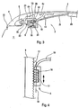
- the chassis 45 of the vehicle is the support element to which the rails 46 are fixed and on which the support means 47 are mounted, the shelf 48 being disposed behind the seat 7 of the seat 7 delimiting the trunk 1 when it is in its retracted position.
- each rail 46 extends mainly in the vertical direction and is substantially vertical over most of its length, its upper end 46a forming a curve that extends rearwardly. and upwards, which allows the shelf 48 to slide behind the backrest 7a, when it is close to its extended position, that is to say when its front edge 48a comes close to the upper rear end 7b of the back 7a, to move back to reach substantially at the latter.
- the support means 47 are formed by two parallel slides 47 which are rectilinear, extend substantially in the vertical direction on either side of the vehicle vehicle and are pivotally mounted on the frame 45 between a retracted position in which the shelf 48 is in its retracted position, and an exit position wherein the tablet 48 is in its extended position.
- Each slide 47 is pivotally mounted on the frame 45 about a pivot axis 49 located at the lower end 47b of the slide 47. Whatever their position, the slideways 47 extends mainly in the vertical direction.
- the shelf 48 comprises two guide elements (not shown) similar to those shown in FIG. 3 and which thus allow the tablet 48 to move relative to the frame 45.
- each guide element is slidably mounted along the slide 47 corresponding, via a roller (similar to the roller 15, fig.3) and pivotally and sliding along the corresponding rail 46, by means of a finger 61 (similar to the finger 16 , fig.3), so that when it is near the lower end 47b of the slide 47, it is also close to the lower end 46b of the rail 46, and when it is close to the upper end 47a of the slide 47, it is also close to the upper end 46a of the rail 46.
- the shelf 48 is in a substantially vertical position when in its retracted position
- the connecting arms 50 supporting the guide elements of the shelf 48, and the substantially planar surface 51 forming the tablet itself is articulated to each other.
- the substantially flat surface 51 is in a substantially horizontal position allowing the recovery of the space which is situated between the front edge 6a of the cover 6 and the backrest 7a of the seat 7 delimiting the chest 1, and, when the tablet 48 is in its retracted position, the substantially flat surface 51 is in a substantially vertical position for storage behind the backrest 7a of the seat 7 defining the trunk 1.
- This articulation makes it possible to have a rear deck system 3 of reduced size.
- the substantially planar surface 51 is pivotally connected to the link arms 50 by an axis of rotation 52 which is oriented in the direction transverse to the vehicle.
- the articulation of the substantially planar surface 51 with respect to the connecting arms 50 is controlled by the displacement of the connecting arms 50 with respect to the frame 45.
- the substantially flat surface 51 comprises, on each side, the front end of its side walls, a lug 53 which is pivotally mounted and sliding along a corresponding ramp 54 which is integral with the frame 45 and which extends substantially in the vertical direction.
- each ramp 54 extends mainly in the vertical direction.
- the ramps make it possible to tilt the substantially flat surface 51 towards the front of the vehicle when the shelf 48 moves from its extended position to its retracted position.
- Each ramp 54 is substantially vertical over most of its length, and its upper end 54a forms a rearwardly-extending curve and terminates substantially horizontally, allowing the substantially planar surface 51 to be a substantially horizontal position when the tablet 48 is in its extended position.
- a return means 55 (such as a spring) connected on the one hand to the substantially planar surface 51 and on the other hand to the corresponding link arm 50 permanently solves the substantially flat surface 51 in its substantially horizontal position.
- slides could be telescopic, as in the case illustrated in Figure 5.
- the vehicle comprises means for controlling the synchronization (not shown) of the movements of the plate 4.48 and the roof 2 so that, when the roof 2 is in its deployed or folded position, the tablet 4 , 48 is respectively in its retracted or retracted positions.
- the rear shelf system may comprise a second shelf (not shown) which is movably mounted between an extended position in which it covers the space between the rear edge of the roof in the deployed position and the seat back defining the trunk, and a retracted position in which it is arranged along the rear window and releases this space.
- the control means of the synchronization of the movements are such that, when the roof is in its deployed position, the first tablet is in its retracted position and the second shelf is in its deployed position, and when the roof is in its folded row position, the first shelf is in its extended position, and the second shelf is in its retracted position.
- the rear shelf system according to the present invention forms an independent module mountable on a vehicle.
- rear shelf system is not limited to the particular embodiment described in detail.
- the rails 5 could be attached to the inner face 6b of the cover 6, for example by screwing or welding, and thus part of the rear shelf module.
- the displacement means could be formed by cylinders whose rod would be integral with the tablet 4.48 and the cylinder would be integral with the support means 9.47, or vice versa.
- the rails could be attached to the seat (backrest) delimiting the trunk, not the chassis.
Landscapes
- Engineering & Computer Science (AREA)
- Mechanical Engineering (AREA)
- Seats For Vehicles (AREA)
- Vehicle Step Arrangements And Article Storage (AREA)
- Warehouses Or Storage Devices (AREA)
- Motor Or Generator Cooling System (AREA)
- Body Structure For Vehicles (AREA)
Claims (26)
- System eines hinteren Deckels (3) für ein Fahrzeug, mit einer Ablageplatte (4, 48), die angepaßt ist, um bewegbar entlang von zwei Schienen (5, 46) gehalten zu sein, zwischen einer ausgefahrenen Position einerseits, in der sie einen Bereich abdeckt, der sich zwischen einem vorderen Rand (6a) der Haube (6) des hinteren Kofferraums (1) des Fahrzeugs und einer Rückenlehne (7a) eines Sitzes (7), der einen Kofferraum (1) des Fahrzeugs begrenzt, befindet, und einer eingeschobenen Position andererseits, in der sie den genannten Bereich freigibt, wobei jede Schiene (5, 46) an einem Tragelement (6, 45) befestigt ist, welches zu dem Fahrzeug gehört und sich im wesentlichen entlang einer Längsrichtung, die das Fahrzeug aufweist, erstreckt, wobei ein Antriebsmittel (8), das einen ersten Teil (10), der an der Ablageplatte (4, 48) befestigt ist, und einen zweiten Teil (11), der mit dem ersten Teil (10) zusammenwirkt, aufweist, dazu angepaßt ist, um die Ablageplatte (4, 48) von ihrer einen Position in die andere zu verlagern, dadurch gekennzeichnet, daß es ein Abstützmittel (9, 47) aufweist, auf dem die Ablageplatte (4, 48) in beweglicher Weise gehalten ist und das dazu angepaßt ist, um in beweglicher Weise auf dem Tragelement (6, 45) angebracht zu sein, und daß der zweite Teil (11) des Antriebsmittels (8) auf dem Abstützmittel (9, 47) befestigt ist, wobei die Verlagerung der Ablageplatte (4, 48) in Bezug auf das Abstützmittel (9, 47) die Verlagerung der Ablageplatte (4, 48) von ihrer einen Position in die andere und die Verlagerung des Abstützmittels (9, 47) in Bezug auf das Tragelement (6, 45) bewirkt.
- System eines hinteren Deckels (3) nach Anspruch 1, dadurch gekennzeichnet, daß das Abstützmittel (9, 47) durch zwei Führungsbahnen (9, 47) gebildet ist, die dazu angepaßt sind, um sich von einer Seite des Fahrzeugs zur anderen zu erstrecken und die in schwenkbarer Weise auf dem Tragelement (6, 45) angebracht sind, wobei die Ablageplatte (4, 48) in verschieblicher Weise entlang der Führungsbahnen (9, 47) und in schwenkbarer und verschieblicher Weise entlang der Schienen (5, 46) gehalten ist.
- System eines hinteren Deckels nach Anspruch 1 oder 2, dadurch gekennzeichnet, daß das Fahrzeug mit einem starren Dach (2) versehen ist, welches zwischen einer ausgebrachten Position, in der es den Fahrgastraum des Fahrzeugs abdeckt, und einer abgelegten Position, in der es in den Kofferraum (1) gefaltet ist, bewegbar ist, wobei sich die Ablageplatte (4, 48) in ihrer ausgefahrenen Position bis in den genannten Bereich erstreckt, der sich zwischen der Rückenlehne (7a) des Sitzes (7) und dem vorderen Rand (6a) der genannten Haube (6) befindet, wobei diesen das genannte starre Dach (2) abdeckt, wenn es sich in seiner ausgebrachten Position befindet.
- System eines hinteren Deckels (3) nach Anspruch 2 oder 3, dadurch gekennzeichnet, daß jede Führungsbahn (9, 47) teleskopierbar ist.
- System eines hinteren Deckels (3) nach einem der Ansprüche 2 bis 4, dadurch gekennzeichnet, daß die Ablageplatte (4, 48) zwei Führungselemente (13) aufweist, wobei jedes Führungselement (13) in verschieblicher Weise entlang der entsprechenden Führungsbahn (9, 47) und in schwenkbarer und verschieblicher Weise entlang der entsprechenden Schiene (5, 46) gehalten ist.
- System eines hinteren Deckels (3) nach Anspruch 5, dadurch gekennzeichnet, daß das Antriebsmittel (8) zwei Zahnstangen (11) und zwei endlose Schrauben (10) aufweist, wobei jede Zahnstange (11) entlang der entsprechenden Führungsbahn (9, 47) gehalten ist, und wobei jede endlose Schraube (10) mit der entsprechenden Zahnstange (11) zusammenwirkt und auf dem entsprechenden Führungselement (13) gehalten ist, auf eine um eine Drehachse (18), die sich im wesentlichen entlang der Längsrichtung erstreckt, drehbare Weise.
- System eines hinteren Deckels (3) nach Anspruch 5 oder 6, dadurch gekennzeichnet, daß jedes Führungselement (13) eine Struktur in Form eines umgekehrten U aufweist, und eine Basiswand (21), eine äußere seitliche Wand (22), die sich ausgehend von der Basiswand (21) erstreckt und auf der Seite des seitlichen Rands (23) des Tragelements (6, 45) angeordnet ist, und eine innere seitliche Wand (24), die sich ausgehend von der Basiswand (21) erstreckt und auf der Seite des mittleren Teils des Tragelements (6, 45) angeordnet ist, aufweist.
- System eines hinteren Deckels (3) nach einem der Ansprüche 5 bis 7, dadurch gekennzeichnet, daß jedes Führungselement (13) einen Führungskopf (15) aufweist, der verschieblich entlang der entsprechenden Führungsbahn (9, 47) gehalten ist, und einen Finger (16), der schwenkbar und verschieblich entlang der entsprechenden Schiene (5, 46) gehalten ist.
- System eines hinteren Deckels (3) nach einem der Ansprüche 7 oder 8, dadurch gekennzeichnet, daß für jedes Führungselement (13) der Finger (16) in Querrichtung in Richtung auf die Außenseite in Bezug auf die seitliche äußere Wand (22) in Richtung auf den seitlichen Rand (23) vorspringt, und daß der Führungskopf (15) in Querrichtung in Richtung auf die Außenseite in Bezug auf die seitliche innere Wand (24) in den Aufnahmeraum (25), der durch die U-förmige Struktur begrenzt ist, vorspringt.
- System eines hinteren Deckels (13) nach einem der Ansprüche 7 bis 9, dadurch gekennzeichnet, daß jede Führungsbahn (9, 47) in dem Aufnahmeraum (25) angeordnet ist, der durch die U-förmige Struktur gebildet ist und eine relative Verschiebebewegung in diesem Aufnahmeraum (25) besitzt.
- System eines hinteren Deckels (3) nach einem der Ansprüche 1 bis 10, dadurch gekennzeichnet, daß das Tragelement (6) durch die Haube (6) des hinteren Kofferraums (1) gebildet ist, wobei die Schienen (5) und die Abstützmittel (9) auf eine solche Weise konfiguriert sind, daß die Ablageplatte (4) angepaßt ist, um unter der Haube (6) angeordnet zu werden, wenn sie sich in ihrer eingezogenen Position befindet.
- System eines hinteren Deckels (3) nach Anspruch 11, soweit auf Anspruch 2 rückbezogen, dadurch gekennzeichnet, daß jede Führungsbahn (9) schwenkbar auf der Haube (6) angebracht ist, durch ihren hinteren Endabschnitt (9b), und dafür angepaßt ist, sich in einer im wesentlichen horizontalen Richtung zu erstrecken.
- System eines hinteren Deckels (3) nach Anspruch 11 oder 12, soweit auf Anspruch 5 rückbezogen, dadurch gekennzeichnet, daß dann, wenn sich das Führungselement (13) in der Nähe des hinteren Endabschnitts (9b) der Führungsbahn (9) befindet, es sich ebenfalls in der Nähe des hinteren Endabschnitts (5b) der Schiene (5) befindet, und wenn es sich in der Nähe des vorderen Endabschnitts (9a) der Führungsbahn (9) befindet, es sich ebenfalls in der Nähe des vorderen Endabschnitts (5a) der Schiene (5) befindet.
- System eines hinteren Deckels (3) nach einem der Ansprüche 1 bis 10, dadurch gekennzeichnet, daß das Tragelement (45) durch die Karosserie (45) des Fahrzeugs gebildet ist, wobei die Schienen (46) und die Abstützmittel (47) auf eine solche Weise konfiguriert sind, daß die Ablageplatte (48) dazu angepaßt ist, hinter der Rückenlehne (7a) des Sitzes (7), der den Kofferraum (1) begrenzt, angeordnet zu sein, wenn sie sich in ihrer eingezogenen Position befindet.
- System eines hinteren Deckels (3) nach Anspruch 14, soweit auf Anspruch 2 rückbezogen, dadurch gekennzeichnet, daß jede Führungsbahn (47) schwenkbar auf der Karosserie (45) angebracht ist, durch ihren inneren Endabschnitt (47b), und dafür angepaßt ist, um sich in einer in wesentlichen vertikalen Richtung zu erstrecken.
- System eines hinteren Deckels (3) nach Anspruch 14 oder 15, soweit auf Anspruch 5 rückbezogen, dadurch gekennzeichnet, daß dann, wenn sich das Führungselement (13) in der Nähe des unteren Endabschnitts (47b) der Führungsbahn (47) befindet, es sich ebenfalls in der Nähe des unteren Endabschnitts (46b) der Schiene (46) befindet, und wenn es sich in der Nähe des oberen Endabschnitts (47a) der Führungsbahn (47) befindet, es sich auch in der Nähe des oberen Endabschnitts (46a) der Schiene (46) befindet.
- System eines hinteren Deckels (3) nach einem der Ansprüche 1 bis 16, dadurch gekennzeichnet, daß die Ablageplatte (4) eine im wesentlichen nicht verformbare Einheit bildet.
- System eines hinteren Deckels (3) nach einem der Ansprüche 1 bis 16, soweit auf Anspruch 5 rückbezogen, dadurch gekennzeichnet, daß die Ablageplatte (48) eine im wesentlichen ebene Oberfläche (51) aufweist, die die eigentliche Ablageplatte bildet, und zwei Verbindungsarme (50), die die Führungselemente (13) tragen und die in Bezug auf die im wesentlichen ebene Oberfläche (51) auf eine solche Weise gelenkig angelenkt sind, daß dann, wenn sich die Ablageplatte (48) in ihrer ausgezogenen Position befindet, die im wesentlichen ebene Oberfläche (51) sich in einer im wesentlichen horizontalen Position befindet, und wenn die Ablageplatte (48) sich in ihrer eingezogenen Position befindet, die im wesentlichen ebene Oberfläche (51) sich in einer in Bezug auf die Horizontale geneigten Position befindet, vorzugsweise in einer im wesentlichen vertikalen Position.
- System eines hinteren Deckels nach Anspruch 18, dadurch gekennzeichnet, daß die im wesentlichen ebene Oberfläche (51) mit den Verbindungsarmen (50) auf eine schwenkbare Weise um eine Drehachse (52) verbunden ist, die entlang der Querrichtung des Fahrzeugs orientiert ist.
- System eines hinteren Deckels (3) nach Anspruch 18 oder 19, dadurch gekennzeichnet, daß ein Rückholmittel (55) die im wesentlichen ebene Oberfläche (51) ständig in ihre im wesentlichen horizontale Position drückt.
- System eines hinteren Deckels (3) nach einem der Ansprüche 18 bis 20, soweit auf Anspruch 14 rückbezogen, dadurch gekennzeichnet, daß die gelenkige Verbindung der im wesentlichen ebenen Oberfläche (51) in Bezug auf die Verbindungsarme (50) durch die Verlagerung der Verbindungsarme (50) in Bezug auf die Karosserie (45) gesteuert wird.
- System eines hinteren Deckels (3) nach Anspruch 21, dadurch gekennzeichnet, daß die im wesentlichen ebene Oberfläche (51) auf jeder Seite an dem vordern Endabschnitt ihrer seitlichen Wände einen Schwenkpunkt (53) aufweist, der schwenkbar und verschieblich entlang einer entsprechenden Rampe (54) gehalten ist, die fest mit der Karosserie (45) verbunden ist und die sich im wesentlichen entlang der vertikalen Richtung erstreckt.
- System eines hinteren Deckels nach einem der vorangehenden Ansprüche, dadurch gekennzeichnet, daß das Fahrzeug mit einem starren Dach (2) versehen ist, das zwischen einer ausgebrachten Position, in der es den Fahrgastraum des Fahrzeugs abdeckt, und einer abgelegten Position, in der es in den Kofferraum (1) hinein gefaltet ist, bewegbar ist, wobei dann, wenn das Dach (2) sich in seiner ausgebrachten Position befindet, die Ablageplatte (4) sich in ihrer eingezogenen Position befindet und unter der Haube (6) angeordnet ist.
- System eines hinteren Deckels nach Anspruch 3 oder 23, dadurch gekennzeichnet, daß dann, wenn sich das Dach (2) in seiner ausgebrachten Position befindet, die Ablageplatte (4, 48) sich in ihrer eingezogenen Position befindet, und wenn sich das Dach in seiner gefalteten, abgelegten Position befindet, die Ablageplatte sich in ihrer ausgezogenen Position befindet.
- System eines hinteren Deckels nach Anspruch 1 oder 2, dadurch gekennzeichnet, daß:- das Fahrzeug mit einem starren Dach (2) versehen ist, welches zwischen einer ausgebrachten Position, in der es den Fahrgastraum des Fahrzeugs abdeckt, und einer abgelegten Position, in der es in den Kofferraum (1) hinein gefaltet ist, bewegbar ist, wobei das genannte System eine zweite Ablageplatte aufweist, die beweglich zwischen einer ausgebrachten Position, in der sie den genannten Zwischenraum abdeckt, der sich zwischen dem hinteren Rand des Dachs, welches sich dann in seiner ausgebrachten Position befindet, und der Rückenlehne (7a) des Sitzes (7), der den Kofferraum begrenzt, befindet, und einer eingezogenen Position, in der sie entlang des Rückfensters angeordnet ist und den genannten Zwischenraum freigibt, gehalten ist,- wenn sich das Dach (2) in seiner ausgebrachten Position befindet, die Ablageplatte (4, 48) sich in ihrer eingezogenen Position befindet, und die zweite Ablageplatte sich in ihrer ausgebrachten Position befindet,- und, wenn sich das Dach in seiner gefalteten, abgelegten Position befindet, die Ablageplatte (4, 48) sich in ihrer ausgezogenen Position befindet und die zweite Ablageplatte sich in ihrer eingezogenen Position befindet.
- Fahrzeug, das mit einem System eines hinteren Deckels (3) nach einem der vorangehenden Ansprüche versehen ist.
Applications Claiming Priority (5)
| Application Number | Priority Date | Filing Date | Title |
|---|---|---|---|
| FR0302490 | 2003-02-28 | ||
| FR0302490A FR2851753B1 (fr) | 2003-02-28 | 2003-02-28 | Systeme de plage arriere de vehicule |
| FR0311378A FR2851751B1 (fr) | 2003-02-28 | 2003-09-29 | Systeme de plage arriere de vehicule |
| FR0311378 | 2003-09-29 | ||
| PCT/FR2004/000380 WO2004078520A2 (fr) | 2003-02-28 | 2004-02-18 | Systeme de plage arriere pour cabriolet |
Publications (2)
| Publication Number | Publication Date |
|---|---|
| EP1599359A2 EP1599359A2 (de) | 2005-11-30 |
| EP1599359B1 true EP1599359B1 (de) | 2006-09-20 |
Family
ID=32852334
Family Applications (1)
| Application Number | Title | Priority Date | Filing Date |
|---|---|---|---|
| EP04712081A Expired - Lifetime EP1599359B1 (de) | 2003-02-28 | 2004-02-18 | System eines hinteren deckels für ein cabriolet |
Country Status (8)
| Country | Link |
|---|---|
| US (1) | US7121602B2 (de) |
| EP (1) | EP1599359B1 (de) |
| JP (1) | JP2006519134A (de) |
| KR (1) | KR20060030464A (de) |
| AT (1) | ATE340100T1 (de) |
| DE (1) | DE602004002463T2 (de) |
| FR (1) | FR2851751B1 (de) |
| WO (1) | WO2004078520A2 (de) |
Families Citing this family (6)
| Publication number | Priority date | Publication date | Assignee | Title |
|---|---|---|---|---|
| DE102004003020A1 (de) * | 2004-01-20 | 2005-08-11 | Wilhelm Karmann Gmbh | Cabriolet-Fahrzeug |
| US20060255619A1 (en) * | 2005-05-16 | 2006-11-16 | Dickie Robert B | Retractable hard top for a four door vehicle |
| DE102006054397A1 (de) | 2006-11-18 | 2008-05-21 | Wilhelm Karmann Gmbh | Cabriolet-Fahrzeug mit einem unter einem Verdeckkastendeckel ablegbaren Verdeck, Verdeckkastenmodul sowie Verfahren zum Betätigen eines Verdeckdeckels |
| FR2910386B1 (fr) | 2006-12-22 | 2009-02-06 | Heuliez Sa | Vehicule a plage mobile a organe de contact doux. |
| DE102009000845A1 (de) * | 2009-02-13 | 2010-08-19 | BSH Bosch und Siemens Hausgeräte GmbH | Kältegerät mit höhenverstellbarem Kühlgutabsteller |
| US9016750B2 (en) * | 2010-10-01 | 2015-04-28 | Cap-Pack Truck Products Llc | Vehicular storage system |
Family Cites Families (23)
| Publication number | Priority date | Publication date | Assignee | Title |
|---|---|---|---|---|
| US2934248A (en) * | 1956-06-25 | 1960-04-26 | Jack A Lown | Station wagon platform accessory |
| US4198091A (en) * | 1978-07-13 | 1980-04-15 | Appleton Arthur I | Vehicle with space tradeable between rear seat and trunk |
| DE3623468A1 (de) * | 1985-07-13 | 1987-01-22 | Nissan Motor | Kraftfahrzeug mit einer hardtop-karosserie und entfernbarem verdeck und ein verfahren zum entfernen und wiederanbringen eines hardtop-verdeckes an einem kraftfahrzeug |
| JPH035237A (ja) * | 1989-05-31 | 1991-01-11 | Mazda Motor Corp | オープンカーのルーフ格納構造 |
| US5209544A (en) * | 1990-09-21 | 1993-05-11 | Fiat Auto S.P.A. | Convertible automobile |
| FR2681292A1 (fr) * | 1991-09-18 | 1993-03-19 | Peugeot | Agencement de vehicule decouvrable. |
| JPH0858387A (ja) * | 1994-08-26 | 1996-03-05 | Kanto Auto Works Ltd | オープンカーの幌収納構造 |
| DE29721430U1 (de) * | 1997-12-04 | 1999-04-01 | Edscha Cabrio-Verdecksysteme GmbH & Co., 94491 Hengersberg | Mehrteiliger Verdeckkastendeckel für Cabrioletfahrzeuge |
| DE29802871U1 (de) * | 1998-02-19 | 1999-06-17 | Edscha Cabrio-Verdecksysteme GmbH & Co., 94491 Hengersberg | Abdeckung für Verdeckkästen von Cabriofahrzeugen |
| DE29812164U1 (de) * | 1998-07-08 | 1999-05-06 | Wilhelm Karmann GmbH, 49084 Osnabrück | Cabriolet-Fahrzeug mit einem Verdeckkasten |
| US6217104B1 (en) * | 1999-06-16 | 2001-04-17 | Cts Fahrzeug Dachsysteme Gmbh | Retractable hard top module |
| JP3523816B2 (ja) | 1999-10-19 | 2004-04-26 | アイシン精機株式会社 | ラッゲージパネル開閉装置 |
| JP4292354B2 (ja) * | 1999-10-19 | 2009-07-08 | アイシン精機株式会社 | 車両用パッケージトレイ |
| US6283533B1 (en) * | 1999-11-29 | 2001-09-04 | Lawrence E. Gavin | Boot cover apparatus |
| FI109777B (fi) * | 2000-03-23 | 2002-10-15 | Valmet Automotive Oy | Kansi avoauton katon säilytystilan peittämiseksi ja avoauto |
| FR2809057B1 (fr) * | 2000-05-17 | 2002-10-11 | Peugeot Citroen Automobiles Sa | Agencement de coffre de vehicule automobile a toit repliable |
| DE10039683B4 (de) * | 2000-08-14 | 2005-02-24 | Wilhelm Karmann Gmbh | Cabriolet-Fahrzeug |
| DE10134370B4 (de) * | 2001-07-14 | 2006-01-05 | Daimlerchrysler Ag | Abdeckvorrichtung für einen Verdeckkasten |
| DE10135223A1 (de) * | 2001-07-24 | 2003-02-27 | Cts Fahrzeug Dachsysteme Gmbh | Abdeckung für einen Verdeckkasten |
| FR2834953B1 (fr) * | 2002-01-21 | 2004-06-04 | France Design | Dispositif de commande d'une tablette arriere de vehicule automobile |
| FR2839474B1 (fr) * | 2002-05-13 | 2005-01-14 | France Design | Plage arriere de vehicule |
| FR2842467B1 (fr) | 2002-07-19 | 2008-07-18 | France Design | Systeme de plage arriere pour vehicule decouvrable a toit rigide repliable |
| DE10245361B4 (de) * | 2002-09-28 | 2005-04-14 | Wilhelm Karmann Gmbh | Cabriolet-Fahrzeug mit versenkbarem Faltverdeck |
-
2003
- 2003-09-29 FR FR0311378A patent/FR2851751B1/fr not_active Expired - Fee Related
-
2004
- 2004-02-18 DE DE602004002463T patent/DE602004002463T2/de not_active Expired - Lifetime
- 2004-02-18 KR KR1020057012574A patent/KR20060030464A/ko not_active Abandoned
- 2004-02-18 US US10/517,127 patent/US7121602B2/en not_active Expired - Fee Related
- 2004-02-18 AT AT04712081T patent/ATE340100T1/de not_active IP Right Cessation
- 2004-02-18 JP JP2006505674A patent/JP2006519134A/ja active Pending
- 2004-02-18 EP EP04712081A patent/EP1599359B1/de not_active Expired - Lifetime
- 2004-02-18 WO PCT/FR2004/000380 patent/WO2004078520A2/fr not_active Ceased
Also Published As
| Publication number | Publication date |
|---|---|
| ATE340100T1 (de) | 2006-10-15 |
| FR2851751A1 (fr) | 2004-09-03 |
| FR2851751B1 (fr) | 2006-06-23 |
| DE602004002463T2 (de) | 2007-09-20 |
| EP1599359A2 (de) | 2005-11-30 |
| WO2004078520A2 (fr) | 2004-09-16 |
| WO2004078520A3 (fr) | 2004-10-14 |
| DE602004002463D1 (de) | 2006-11-02 |
| US7121602B2 (en) | 2006-10-17 |
| US20060091686A1 (en) | 2006-05-04 |
| JP2006519134A (ja) | 2006-08-24 |
| KR20060030464A (ko) | 2006-04-10 |
Similar Documents
| Publication | Publication Date | Title |
|---|---|---|
| WO2001045976A1 (fr) | Toit escamotable dans le coffre arriere d'un vehicule | |
| EP1597104B1 (de) | Verriegelung eines versenkbaren fahrzeugdachs | |
| EP1599359B1 (de) | System eines hinteren deckels für ein cabriolet | |
| FR2853868A1 (fr) | Systeme de plage arriere escamotable pour vehicule decouvrable a toit repliable | |
| EP1597101B1 (de) | Versenkbares dach für ein fahrzeug | |
| EP1711361B1 (de) | In einem kraftfahrzeugkofferraum versenkbares dach, mit verlagerbaren seitenteilen | |
| EP1644212A2 (de) | Fahrzeug mit einem einziehbaren offenen verdeck und verfahren zum verstauen dieses verdecks mit einem horizontalen kippsystem | |
| EP1320467A1 (de) | Versenkbares dach für ein fahrzeug und fahrzeug, insbesondere vom typ pick-up, mit einem solchen dach | |
| WO2003062002A1 (fr) | Tablette arriere pour vehicule automobile dote d'un toit repliable | |
| EP1467882A1 (de) | Vorrichtung zur betätigung einer kofferraumbrücke an einem kraftfahrzeug | |
| FR2853601A1 (fr) | Systeme de plage arriere de vehicule | |
| EP1633585B1 (de) | Fahrzeug mit einem vertikal klappbaren sonnendach | |
| FR2608528A1 (fr) | Toit ouvrant pour vehicules | |
| FR2851753A1 (fr) | Systeme de plage arriere de vehicule | |
| EP1556239B1 (de) | Modulare montageeinheit für ein kfz mit faltbarem dach und ein kfz mit solch einer einheit | |
| FR2828838A1 (fr) | Vehicule automobile de type berline transformable en un vehicule automobile a benne ouverte vers le haut | |
| FR2880851A1 (fr) | Marchepied escamotable pour porte coulissante de vehicule automobile et vehicule correspondant. | |
| WO2005075230A1 (fr) | Toit escamotable de vehicule | |
| FR2845950A1 (fr) | Toit escamotable pour vehicule | |
| FR2854353A1 (fr) | Element arriere de toit escamotable et vehicule ainsi equipe | |
| WO2004091952A2 (fr) | Mecanisme de toit rigide escamotable de vehicule automobile | |
| FR2834950A1 (fr) | Dispositif de commande d'une tablette arriere de vehicule automobile | |
| FR2872456A1 (fr) | Toit rigide pliable | |
| EP1648725A2 (de) | Hinteres faltdachelement und damit ausgestattetes fahrzeug | |
| WO2005075229A1 (fr) | Toit escamotable de vehicule |
Legal Events
| Date | Code | Title | Description |
|---|---|---|---|
| PUAI | Public reference made under article 153(3) epc to a published international application that has entered the european phase |
Free format text: ORIGINAL CODE: 0009012 |
|
| 17P | Request for examination filed |
Effective date: 20050701 |
|
| AK | Designated contracting states |
Kind code of ref document: A2 Designated state(s): AT BE BG CH CY CZ DE DK EE ES FI FR GB GR HU IE IT LI LU MC NL PT RO SE SI SK TR |
|
| AX | Request for extension of the european patent |
Extension state: AL LT LV MK |
|
| 111L | Licence recorded |
Free format text: 0100 FRANCE DESIGN Effective date: 20051227 |
|
| GRAP | Despatch of communication of intention to grant a patent |
Free format text: ORIGINAL CODE: EPIDOSNIGR1 |
|
| DAX | Request for extension of the european patent (deleted) | ||
| GRAS | Grant fee paid |
Free format text: ORIGINAL CODE: EPIDOSNIGR3 |
|
| GRAA | (expected) grant |
Free format text: ORIGINAL CODE: 0009210 |
|
| AK | Designated contracting states |
Kind code of ref document: B1 Designated state(s): AT BE BG CH CY CZ DE DK EE ES FI FR GB GR HU IE IT LI LU MC NL PT RO SE SI SK TR |
|
| PG25 | Lapsed in a contracting state [announced via postgrant information from national office to epo] |
Ref country code: FI Free format text: LAPSE BECAUSE OF FAILURE TO SUBMIT A TRANSLATION OF THE DESCRIPTION OR TO PAY THE FEE WITHIN THE PRESCRIBED TIME-LIMIT Effective date: 20060920 Ref country code: IE Free format text: LAPSE BECAUSE OF FAILURE TO SUBMIT A TRANSLATION OF THE DESCRIPTION OR TO PAY THE FEE WITHIN THE PRESCRIBED TIME-LIMIT Effective date: 20060920 Ref country code: SI Free format text: LAPSE BECAUSE OF FAILURE TO SUBMIT A TRANSLATION OF THE DESCRIPTION OR TO PAY THE FEE WITHIN THE PRESCRIBED TIME-LIMIT Effective date: 20060920 Ref country code: AT Free format text: LAPSE BECAUSE OF FAILURE TO SUBMIT A TRANSLATION OF THE DESCRIPTION OR TO PAY THE FEE WITHIN THE PRESCRIBED TIME-LIMIT Effective date: 20060920 Ref country code: NL Free format text: LAPSE BECAUSE OF FAILURE TO SUBMIT A TRANSLATION OF THE DESCRIPTION OR TO PAY THE FEE WITHIN THE PRESCRIBED TIME-LIMIT Effective date: 20060920 Ref country code: SK Free format text: LAPSE BECAUSE OF FAILURE TO SUBMIT A TRANSLATION OF THE DESCRIPTION OR TO PAY THE FEE WITHIN THE PRESCRIBED TIME-LIMIT Effective date: 20060920 Ref country code: CZ Free format text: LAPSE BECAUSE OF FAILURE TO SUBMIT A TRANSLATION OF THE DESCRIPTION OR TO PAY THE FEE WITHIN THE PRESCRIBED TIME-LIMIT Effective date: 20060920 Ref country code: RO Free format text: LAPSE BECAUSE OF FAILURE TO SUBMIT A TRANSLATION OF THE DESCRIPTION OR TO PAY THE FEE WITHIN THE PRESCRIBED TIME-LIMIT Effective date: 20060920 Ref country code: IT Free format text: LAPSE BECAUSE OF FAILURE TO SUBMIT A TRANSLATION OF THE DESCRIPTION OR TO PAY THE FEE WITHIN THE PRESCRIBED TIME-LIMIT;WARNING: LAPSES OF ITALIAN PATENTS WITH EFFECTIVE DATE BEFORE 2007 MAY HAVE OCCURRED AT ANY TIME BEFORE 2007. THE CORRECT EFFECTIVE DATE MAY BE DIFFERENT FROM THE ONE RECORDED. Effective date: 20060920 |
|
| REG | Reference to a national code |
Ref country code: GB Ref legal event code: FG4D Free format text: NOT ENGLISH |
|
| REG | Reference to a national code |
Ref country code: CH Ref legal event code: EP |
|
| RAP2 | Party data changed (patent owner data changed or rights of a patent transferred) |
Owner name: SOCIETE EUROPEENNE DE BREVETS AUTOMOBILES - SEBA |
|
| REG | Reference to a national code |
Ref country code: IE Ref legal event code: FG4D Free format text: LANGUAGE OF EP DOCUMENT: FRENCH |
|
| REF | Corresponds to: |
Ref document number: 602004002463 Country of ref document: DE Date of ref document: 20061102 Kind code of ref document: P |
|
| PG25 | Lapsed in a contracting state [announced via postgrant information from national office to epo] |
Ref country code: DK Free format text: LAPSE BECAUSE OF FAILURE TO SUBMIT A TRANSLATION OF THE DESCRIPTION OR TO PAY THE FEE WITHIN THE PRESCRIBED TIME-LIMIT Effective date: 20061220 Ref country code: SE Free format text: LAPSE BECAUSE OF FAILURE TO SUBMIT A TRANSLATION OF THE DESCRIPTION OR TO PAY THE FEE WITHIN THE PRESCRIBED TIME-LIMIT Effective date: 20061220 Ref country code: BG Free format text: LAPSE BECAUSE OF FAILURE TO SUBMIT A TRANSLATION OF THE DESCRIPTION OR TO PAY THE FEE WITHIN THE PRESCRIBED TIME-LIMIT Effective date: 20061220 |
|
| PG25 | Lapsed in a contracting state [announced via postgrant information from national office to epo] |
Ref country code: ES Free format text: LAPSE BECAUSE OF FAILURE TO SUBMIT A TRANSLATION OF THE DESCRIPTION OR TO PAY THE FEE WITHIN THE PRESCRIBED TIME-LIMIT Effective date: 20061231 |
|
| NLT2 | Nl: modifications (of names), taken from the european patent patent bulletin |
Owner name: SOCIETE EUROPEENNE DE BREVETS AUTOMOBILES - SEBA Effective date: 20061025 |
|
| PG25 | Lapsed in a contracting state [announced via postgrant information from national office to epo] |
Ref country code: MC Free format text: LAPSE BECAUSE OF NON-PAYMENT OF DUE FEES Effective date: 20070228 |
|
| NLV1 | Nl: lapsed or annulled due to failure to fulfill the requirements of art. 29p and 29m of the patents act | ||
| PG25 | Lapsed in a contracting state [announced via postgrant information from national office to epo] |
Ref country code: PT Free format text: LAPSE BECAUSE OF FAILURE TO SUBMIT A TRANSLATION OF THE DESCRIPTION OR TO PAY THE FEE WITHIN THE PRESCRIBED TIME-LIMIT Effective date: 20070312 |
|
| GBT | Gb: translation of ep patent filed (gb section 77(6)(a)/1977) |
Effective date: 20070215 |
|
| RAP2 | Party data changed (patent owner data changed or rights of a patent transferred) |
Owner name: SOCIETE EUROPEENNE DE BREVETS AUTOMOBILES |
|
| REG | Reference to a national code |
Ref country code: IE Ref legal event code: FD4D |
|
| PLBE | No opposition filed within time limit |
Free format text: ORIGINAL CODE: 0009261 |
|
| STAA | Information on the status of an ep patent application or granted ep patent |
Free format text: STATUS: NO OPPOSITION FILED WITHIN TIME LIMIT |
|
| 26N | No opposition filed |
Effective date: 20070621 |
|
| BERE | Be: lapsed |
Owner name: SOC. EUROPEENNE DES BREVETS AUTOMOBILES Effective date: 20070228 |
|
| PG25 | Lapsed in a contracting state [announced via postgrant information from national office to epo] |
Ref country code: BE Free format text: LAPSE BECAUSE OF NON-PAYMENT OF DUE FEES Effective date: 20070228 |
|
| PG25 | Lapsed in a contracting state [announced via postgrant information from national office to epo] |
Ref country code: GR Free format text: LAPSE BECAUSE OF FAILURE TO SUBMIT A TRANSLATION OF THE DESCRIPTION OR TO PAY THE FEE WITHIN THE PRESCRIBED TIME-LIMIT Effective date: 20061221 |
|
| PG25 | Lapsed in a contracting state [announced via postgrant information from national office to epo] |
Ref country code: EE Free format text: LAPSE BECAUSE OF FAILURE TO SUBMIT A TRANSLATION OF THE DESCRIPTION OR TO PAY THE FEE WITHIN THE PRESCRIBED TIME-LIMIT Effective date: 20060920 |
|
| REG | Reference to a national code |
Ref country code: CH Ref legal event code: PL |
|
| PG25 | Lapsed in a contracting state [announced via postgrant information from national office to epo] |
Ref country code: CH Free format text: LAPSE BECAUSE OF NON-PAYMENT OF DUE FEES Effective date: 20080229 Ref country code: LI Free format text: LAPSE BECAUSE OF NON-PAYMENT OF DUE FEES Effective date: 20080229 |
|
| PG25 | Lapsed in a contracting state [announced via postgrant information from national office to epo] |
Ref country code: LU Free format text: LAPSE BECAUSE OF NON-PAYMENT OF DUE FEES Effective date: 20070218 Ref country code: CY Free format text: LAPSE BECAUSE OF FAILURE TO SUBMIT A TRANSLATION OF THE DESCRIPTION OR TO PAY THE FEE WITHIN THE PRESCRIBED TIME-LIMIT Effective date: 20060920 |
|
| PG25 | Lapsed in a contracting state [announced via postgrant information from national office to epo] |
Ref country code: HU Free format text: LAPSE BECAUSE OF FAILURE TO SUBMIT A TRANSLATION OF THE DESCRIPTION OR TO PAY THE FEE WITHIN THE PRESCRIBED TIME-LIMIT Effective date: 20070321 Ref country code: TR Free format text: LAPSE BECAUSE OF FAILURE TO SUBMIT A TRANSLATION OF THE DESCRIPTION OR TO PAY THE FEE WITHIN THE PRESCRIBED TIME-LIMIT Effective date: 20060920 |
|
| PGFP | Annual fee paid to national office [announced via postgrant information from national office to epo] |
Ref country code: IT Payment date: 20120213 Year of fee payment: 9 |
|
| PGFP | Annual fee paid to national office [announced via postgrant information from national office to epo] |
Ref country code: GB Payment date: 20130213 Year of fee payment: 10 Ref country code: DE Payment date: 20130213 Year of fee payment: 10 |
|
| PGFP | Annual fee paid to national office [announced via postgrant information from national office to epo] |
Ref country code: FR Payment date: 20130717 Year of fee payment: 10 |
|
| REG | Reference to a national code |
Ref country code: DE Ref legal event code: R119 Ref document number: 602004002463 Country of ref document: DE |
|
| GBPC | Gb: european patent ceased through non-payment of renewal fee |
Effective date: 20140218 |
|
| REG | Reference to a national code |
Ref country code: FR Ref legal event code: ST Effective date: 20141031 |
|
| REG | Reference to a national code |
Ref country code: DE Ref legal event code: R119 Ref document number: 602004002463 Country of ref document: DE Effective date: 20140902 |
|
| PG25 | Lapsed in a contracting state [announced via postgrant information from national office to epo] |
Ref country code: DE Free format text: LAPSE BECAUSE OF NON-PAYMENT OF DUE FEES Effective date: 20140902 Ref country code: GB Free format text: LAPSE BECAUSE OF NON-PAYMENT OF DUE FEES Effective date: 20140218 Ref country code: FR Free format text: LAPSE BECAUSE OF NON-PAYMENT OF DUE FEES Effective date: 20140228 |
|
| PG25 | Lapsed in a contracting state [announced via postgrant information from national office to epo] |
Ref country code: IT Free format text: LAPSE BECAUSE OF NON-PAYMENT OF DUE FEES Effective date: 20140218 |
|
| REG | Reference to a national code |
Ref country code: CH Ref legal event code: PK Free format text: COMPLEMENT D'ENREGISTREMENT DE LICENCE: LICENCE NON-EXCLUSIVE |