EP1599359B1 - Package shelf for a convertible - Google Patents
Package shelf for a convertible Download PDFInfo
- Publication number
- EP1599359B1 EP1599359B1 EP04712081A EP04712081A EP1599359B1 EP 1599359 B1 EP1599359 B1 EP 1599359B1 EP 04712081 A EP04712081 A EP 04712081A EP 04712081 A EP04712081 A EP 04712081A EP 1599359 B1 EP1599359 B1 EP 1599359B1
- Authority
- EP
- European Patent Office
- Prior art keywords
- shelf
- set forth
- vehicle
- shelf assembly
- along
- Prior art date
- Legal status (The legal status is an assumption and is not a legal conclusion. Google has not performed a legal analysis and makes no representation as to the accuracy of the status listed.)
- Expired - Lifetime
Links
Images


Classifications
-
- B—PERFORMING OPERATIONS; TRANSPORTING
- B60—VEHICLES IN GENERAL
- B60R—VEHICLES, VEHICLE FITTINGS, OR VEHICLE PARTS, NOT OTHERWISE PROVIDED FOR
- B60R5/00—Compartments within vehicle body primarily intended or sufficiently spacious for trunks, suit-cases, or the like
- B60R5/04—Compartments within vehicle body primarily intended or sufficiently spacious for trunks, suit-cases, or the like arranged at rear of vehicle
-
- B—PERFORMING OPERATIONS; TRANSPORTING
- B60—VEHICLES IN GENERAL
- B60J—WINDOWS, WINDSCREENS, NON-FIXED ROOFS, DOORS, OR SIMILAR DEVICES FOR VEHICLES; REMOVABLE EXTERNAL PROTECTIVE COVERINGS SPECIALLY ADAPTED FOR VEHICLES
- B60J7/00—Non-fixed roofs; Roofs with movable panels, e.g. rotary sunroofs
- B60J7/20—Vehicle storage compartments for roof parts or for collapsible flexible tops
- B60J7/202—Vehicle storage compartments for roof parts or for collapsible flexible tops being characterised by moveable cover parts for closing the gap between boot lid and rearmost seats
Definitions
- the present invention relates to a rear shelf system for a vehicle, in particular for a vehicle having a movable hard roof that can be folded into the rear boot.
- a rear shelf system of the type comprising a tablet adapted to be mounted movably along two rails between, on the one hand, an extended position in which it covers a space between the front edge of the trunk lid of the vehicle and the seat back defining the trunk, and, secondly, a retracted position in which it releases this space, each rail being fixed to a support element of the vehicle and extending substantially in the longitudinal direction of the vehicle, means drive, which comprise a first portion integral with the tablet and a second portion cooperating with the first portion, being adapted to move the tablet from one to the other of its positions.
- the problem is to realize a rear shelf system that can form an independent assembly that can be delivered in kit form, the mounting on the vehicle does not require intervention on the drive means.
- One solution is a rear shelf system of the aforementioned type comprising support means on which the shelf is movably mounted and which are adapted to be movably mounted on the support element, the second part of the drive means being secured to the support means, the movement of the tablet relative to the support means imposing that of the tablet from one to the other of its positions and that of the support means relative to the support member of the vehicle.
- the rear shelf system comprises the tablet, the support means and the drive means that generate an action force on the tablet and the corresponding reaction force on the support means, the rails being used only to guide the movement of the tablet.
- the mounting of a rear shelf system according to the present invention on the vehicle is particularly simple: the support means are mounted on the support member, and the shelf is mounted along the rails.
- the precise positioning of the two parts of the driving means relative to each other is done during the assembly of the rear shelf system during which the drive means are easily accessible, the rear shelf system being more easily manipulable.
- the support element to which the rails are secured and on which the support means is mounted is the boot of the trunk.
- the rails and the support means are configured such that the tablet is adapted to be disposed under the hood when it is in its retracted position.
- the support means are formed by two rails which are adapted to extend substantially in the longitudinal direction and on either side of the vehicle, and which are pivotally mounted on the hood, the shelf being slidably mounted along the rails and pivotally and slidably along the rails.
- the support element to which the rails are secured and on which the support means is mounted is the chassis of the vehicle.
- the rails and the support means are configured such that the tablet is adapted to be disposed behind the backrest delimiting the rear trunk when it is in its retracted position.
- the support means are formed by two slideways which are adapted to extend substantially in a direction inclined relative to the horizontal, preferably the vertical direction and of both sides. other of the vehicle, and which are pivotally mounted on the frame, the shelf being slidably mounted along the rails and pivotally and slidably along the rails.
- the tablet comprises a substantially flat surface forming the actual tablet and connecting arms which support guide elements ensuring the mechanical connections of the tablet to the rails and the support means, and which are hinged to the substantially planar surface so that, when the tablet is in its extended position, the substantially planar surface is in a substantially horizontal position and, when the tablet is in its retracted position, the substantially planar surface is in a position inclined relative to the horizontal, preferably in a substantially vertical position.
- the tablet can thus pivot behind the backrest delimiting the trunk, in order to allow the passage of a retractable roof, while limiting the size of the drive device of the tablet.
- a vehicle comprises a rear trunk 1 and a rigid roof 2 folding.
- the roof 2 is movable between an extended position in which it covers the passenger compartment of the vehicle, and a position 5 folded row in which it is folded in the trunk 1.
- the vehicle also includes a rear shelf system 3 which includes a 4.48 shelf.
- the tablet 4.48 is movably mounted along two parallel rails 5.46 which are attached to a support element 6.45 of the vehicle and which extend, on each side of this element, substantially in the longitudinal direction of the vehicle. vehicle.
- the tablet 4.48 is movable between an extended position and a retracted position. When it is in the extended position, the shelf 4,48 covers the space which is situated between the front edge 6a of the cover 6 and the backrest 7a of the seat 7 delimiting the trunk 1 (FIG. 1), and when it is in the retracted position , the 4.48 tablet frees this space ( Figure 2).
- Drive means 8 are adapted to move the tablet 4.48 from one to the other of its positions.
- the rear shelf system 3 also comprises support means 9,47 and the drive means 8.
- the tablet 4.48 is movably mounted on the support means 9.47 which are mounted movably on the support element 6.45 to which the rails 5.46 are fixed.
- the drive means 8 comprise a first portion 10 and a second portion 11.
- the first portion 10 is fixed to the tablet 4.48 and the second portion 11 is fixed to the support means 9.47.
- the drive means 8 cause the tablet 4,48 to move relative to the support means 9,47.
- the shape of the rails 5.46 in the longitudinal and vertical directions is adapted to the predetermined kinematics of the tablet 4.48.
- the hood 6 of the rear trunk 1 is the support element to which the rails 5 are fixed and on which the support means 9 are mounted, the tablet 4 being arranged under the hood 6 when in its retracted position.
- each rail 5 extends mainly in the longitudinal direction and is substantially horizontal over most of its length, its front end 5a forming a curve which extends forward and upwards, which allows the tablet 4 to slide under the hood 6 and, when it is close to its extended position, that is to say when its rear edge 4b comes close to the front edge 6a of the hood 6 , to move upward to reach substantially the level of the latter.
- the rails 5 are made by stamping on the inner face 6b of the cover 6.
- the support means 9 are formed by two parallel rails 9 which are rectilinear, extend substantially in the longitudinal direction on either side of the vehicle of the vehicle and are mounted pivotally on the cover 6 between a retracted position in which the tablet 4 is in its retracted position, and an output position in which the tablet 4 is in its extended position.
- Each slide 9 is pivotally mounted on the cover 6 about a pivot axis 12 located at the rear end 9b of the slide 9. Whatever their position, the slides 9 extends mainly in the longitudinal direction.
- the tablet 4 has two guide elements 13, each of them being fixed to a corresponding transverse edge 4c of the tablet 4 by a connecting arm 14.
- the substantially flat surface forming the tablet itself, the guide elements 13 and the connecting arm 14 form a shelf 4 substantially indeformable.
- Each guide element 13 is adapted to ensure the mechanical connections between the first tablet 4, and, on the other hand, the slide 9 and the corresponding rail 5.
- each guide element 13 comprises a roller 15 by which the tablet 4 is slidably mounted along the corresponding slideway 9, and a finger 16 through which the tablet 4 is pivotally and slidably mounted on along the corresponding rail 5.
- the first portion 10 of the drive means 8 is formed by two worm screws 10 and the second portion 11 of the drive means 8 is formed by two racks 11.
- Each of the racks 11 is mounted along a corresponding slide 9 and extends, therefore, substantially in the longitudinal direction of the vehicle.
- Each worm 10 is housed in a cavity 17 made in the corresponding guide element 13 and is rotatably mounted in this cavity 17 about an axis of rotation 18 extending substantially in the longitudinal direction of the vehicle, so that to cooperate with the corresponding rack 11.
- a motor 19 is fixed to the lower surface of the tablet 4 and transmission means 20, for example hoses, allow the movement of the motor shaft 19 to be transmitted to the two worms 10.
- the rail 5, the slide 9 and the guide element 13 are arranged such that, when a guide element 13 is close to the rear end 9b of the corresponding slideway 9, it is also near the rear end 5b of the corresponding rail 5, the slide 9 being in its retracted position and the tablet 4 being in its retracted position ( Figure 2). And when it is close to the front end 9a of the corresponding slide 9, it is also close to the front end 5a of the corresponding rail 5, the slide 9 being in its output position and the tablet 4 being in its extended position ( Figure 1).
- each worm 10 is rotated in one direction or the other by the means transmission 20 and cooperates with the rack 11 corresponding to cause the translation of each roller 15 along the corresponding slide 9.
- the slides 9 being connected to the cover 6 by their pivot axis 12, their translation relative to the cover 6 is impossible, and, as a result, the two rollers 15 and the two fingers 16 have the same translational movement relative to the hood 6.
- Each finger 16 pivots and slides along the corresponding rail 5 so as to impose on the tablet 4 its trajectory, each roller 15 sliding along the corresponding rectilinear slide 9 which pivots relative to the cover 6 so as to allow the displacement of the tablet 4 relative to the cover 6.
- each guide element 13 has an inverted U-shaped structure and has a substantially horizontal base wall 21, an outer lateral wall 22 which extends downwards from the wall 21 and which is disposed on the side of the side edge 23 of the cover 6, and an inner side wall 24 which extends downwardly from the base wall 20 and which is arranged on the side of the middle portion of the hood 6.
- the finger 16 protrudes transversely outwards with respect to the outer lateral wall 22 in the direction of the lateral edge 23 and penetrates into the corresponding rail 5 which is formed along this edge 23.
- the roller 15 projects transversely towards the side 23 external to the inner side wall 24 in the housing 25 which is delimited by the U-shaped structure, and enters the slide 9 which has a relative sliding movement in this housing 25.
- This The particular shape of the guide element 13 makes the rear shelf system 3 particularly compact.
- each slide 9 is telescopic so as to occupy as little space as possible in the retracted position.
- Each slide 9 comprises, for this purpose, a rear element 30, a front element 31 and transmission means 32.
- the rear member 30 is pivotally mounted on the cover 6 about the pivot axis 12 which is located at the rear 30b of the rear member 30.
- the front member 31 is slidably mounted along the rear member 30, the tablet 4 being slidably mounted along the front element 31.
- the guide element 13 comprises a strip 33 through which the tablet 4 is slidably mounted along the front element 31.
- the first portion 10 of the drive means 8 is formed by a pinion 10 which is mounted on the strip 33 by a transverse axis of rotation 34 transverse to the vehicle and which is meshed with the rack 11 which extends along the front element 31.
- the rotation of the pinion 10 causes the sliding of the tablet 4 along the front element 31.
- the transmission means 32 make it possible to generate the sliding of the rear element 30 with respect to the front element 31.
- the transmission means 32 comprise, for each slide 9, two connecting cables 35 and two pulleys. reference 36.
- Each connecting cable 35 is fixed, by its first end 37, to the strip 33, and by its second end 38, to the rear element 30.
- Each connecting cable 35 is wound around a corresponding pulley 36 which is mounted on a corresponding end of the front element 31 by an axis of rotation 39 transverse to the vehicle.
- a transmission pinion 40 which is mounted on the front element 31 by an axis of rotation 41 transverse to the vehicle, is meshed with a transmission rack 42 which extends along the rear element 30.
- the rotation of the pinion 10 in one direction or the other directly causes the relative movement of the tablet 4 relative to the front slide element 31. Due to this relative displacement, and the presence of the connecting cables 35, the transmission pinion 40 and the transmission rack 42, the front element 31 slides relative to the rear element 30 in the same direction as the sliding of the strip 33 relative to the front element 31.
- the chassis 45 of the vehicle is the support element to which the rails 46 are fixed and on which the support means 47 are mounted, the shelf 48 being disposed behind the seat 7 of the seat 7 delimiting the trunk 1 when it is in its retracted position.
- each rail 46 extends mainly in the vertical direction and is substantially vertical over most of its length, its upper end 46a forming a curve that extends rearwardly. and upwards, which allows the shelf 48 to slide behind the backrest 7a, when it is close to its extended position, that is to say when its front edge 48a comes close to the upper rear end 7b of the back 7a, to move back to reach substantially at the latter.
- the support means 47 are formed by two parallel slides 47 which are rectilinear, extend substantially in the vertical direction on either side of the vehicle vehicle and are pivotally mounted on the frame 45 between a retracted position in which the shelf 48 is in its retracted position, and an exit position wherein the tablet 48 is in its extended position.
- Each slide 47 is pivotally mounted on the frame 45 about a pivot axis 49 located at the lower end 47b of the slide 47. Whatever their position, the slideways 47 extends mainly in the vertical direction.
- the shelf 48 comprises two guide elements (not shown) similar to those shown in FIG. 3 and which thus allow the tablet 48 to move relative to the frame 45.
- each guide element is slidably mounted along the slide 47 corresponding, via a roller (similar to the roller 15, fig.3) and pivotally and sliding along the corresponding rail 46, by means of a finger 61 (similar to the finger 16 , fig.3), so that when it is near the lower end 47b of the slide 47, it is also close to the lower end 46b of the rail 46, and when it is close to the upper end 47a of the slide 47, it is also close to the upper end 46a of the rail 46.
- the shelf 48 is in a substantially vertical position when in its retracted position
- the connecting arms 50 supporting the guide elements of the shelf 48, and the substantially planar surface 51 forming the tablet itself is articulated to each other.
- the substantially flat surface 51 is in a substantially horizontal position allowing the recovery of the space which is situated between the front edge 6a of the cover 6 and the backrest 7a of the seat 7 delimiting the chest 1, and, when the tablet 48 is in its retracted position, the substantially flat surface 51 is in a substantially vertical position for storage behind the backrest 7a of the seat 7 defining the trunk 1.
- This articulation makes it possible to have a rear deck system 3 of reduced size.
- the substantially planar surface 51 is pivotally connected to the link arms 50 by an axis of rotation 52 which is oriented in the direction transverse to the vehicle.
- the articulation of the substantially planar surface 51 with respect to the connecting arms 50 is controlled by the displacement of the connecting arms 50 with respect to the frame 45.
- the substantially flat surface 51 comprises, on each side, the front end of its side walls, a lug 53 which is pivotally mounted and sliding along a corresponding ramp 54 which is integral with the frame 45 and which extends substantially in the vertical direction.
- each ramp 54 extends mainly in the vertical direction.
- the ramps make it possible to tilt the substantially flat surface 51 towards the front of the vehicle when the shelf 48 moves from its extended position to its retracted position.
- Each ramp 54 is substantially vertical over most of its length, and its upper end 54a forms a rearwardly-extending curve and terminates substantially horizontally, allowing the substantially planar surface 51 to be a substantially horizontal position when the tablet 48 is in its extended position.
- a return means 55 (such as a spring) connected on the one hand to the substantially planar surface 51 and on the other hand to the corresponding link arm 50 permanently solves the substantially flat surface 51 in its substantially horizontal position.
- slides could be telescopic, as in the case illustrated in Figure 5.
- the vehicle comprises means for controlling the synchronization (not shown) of the movements of the plate 4.48 and the roof 2 so that, when the roof 2 is in its deployed or folded position, the tablet 4 , 48 is respectively in its retracted or retracted positions.
- the rear shelf system may comprise a second shelf (not shown) which is movably mounted between an extended position in which it covers the space between the rear edge of the roof in the deployed position and the seat back defining the trunk, and a retracted position in which it is arranged along the rear window and releases this space.
- the control means of the synchronization of the movements are such that, when the roof is in its deployed position, the first tablet is in its retracted position and the second shelf is in its deployed position, and when the roof is in its folded row position, the first shelf is in its extended position, and the second shelf is in its retracted position.
- the rear shelf system according to the present invention forms an independent module mountable on a vehicle.
- rear shelf system is not limited to the particular embodiment described in detail.
- the rails 5 could be attached to the inner face 6b of the cover 6, for example by screwing or welding, and thus part of the rear shelf module.
- the displacement means could be formed by cylinders whose rod would be integral with the tablet 4.48 and the cylinder would be integral with the support means 9.47, or vice versa.
- the rails could be attached to the seat (backrest) delimiting the trunk, not the chassis.
Landscapes
- Engineering & Computer Science (AREA)
- Mechanical Engineering (AREA)
- Seats For Vehicles (AREA)
- Vehicle Step Arrangements And Article Storage (AREA)
- Warehouses Or Storage Devices (AREA)
- Body Structure For Vehicles (AREA)
- Motor Or Generator Cooling System (AREA)
Abstract
Description
La présente invention concerne un système de plage arrière pour véhicule, notamment pour un véhicule comportant un toit rigide mobile repliable dans le coffre arrière.The present invention relates to a rear shelf system for a vehicle, in particular for a vehicle having a movable hard roof that can be folded into the rear boot.
On connaît un système de plage arrière du type comportant une tablette adaptée à être montée mobile le long de deux rails entre, d'une part, une position sortie dans laquelle elle recouvre un espace situé entre le bord avant du capot du coffre arrière du véhicule et le dossier du siège délimitant le coffre, et, d'autre part, une position escamotée dans laquelle elle libère cet espace, chaque rail étant fixé à un élément support du véhicule et s'étendant sensiblement selon la direction longitudinale du véhicule, des moyens d'entraînement, qui comprennent une première partie solidaire de la tablette et une deuxième partie coopérant avec la première partie, étant adaptés à déplacer la tablette de l'une à l'autre de ses positions.There is known a rear shelf system of the type comprising a tablet adapted to be mounted movably along two rails between, on the one hand, an extended position in which it covers a space between the front edge of the trunk lid of the vehicle and the seat back defining the trunk, and, secondly, a retracted position in which it releases this space, each rail being fixed to a support element of the vehicle and extending substantially in the longitudinal direction of the vehicle, means drive, which comprise a first portion integral with the tablet and a second portion cooperating with the first portion, being adapted to move the tablet from one to the other of its positions.
Un tel système est décrit dans FR-A-2 842 467 ou US 2001/004156. Dans ces documents, les rails et la deuxième partie des moyens d'entraînement sont solidaires du capot du coffre arrière. De façon connue, les moyens d'entraînement génèrent une force d'action sur la tablette et la force de réaction correspondante sur le capot, ce qui permet de déplacer la tablette par rapport au capot.Such a system is described in FR-A-2 842 467 or US 2001/004156. In these documents, the rails and the second part of the drive means are integral with the trunk lid. In a known manner, the drive means generate an action force on the tablet and the corresponding reaction force on the cover, which makes it possible to move the tablet relative to the cover.
Toutefois, le montage d'un tel système de plage arrière sur un véhicule n'est pas aisé. En effet, il est nécessaire de disposer précisément la première partie des moyens d'entraînement par rapport à la deuxième partie afin de permettre le déplacement de la tablette, ce qui est délicat vu la faible accessibilité à ces moyens d'entraînement.However, mounting such a rear shelf system on a vehicle is not easy. Indeed, it is necessary to have precisely the first part of the drive means relative to the second part to allow the movement of the tablet, which is difficult given the low accessibility to these drive means.
Le problème posé est de réaliser un système de plage arrière pouvant former un ensemble indépendant pouvant être livré sous forme de kit, dont le montage sur le véhicule ne nécessite pas d'intervention sur les moyens d'entraînement.The problem is to realize a rear shelf system that can form an independent assembly that can be delivered in kit form, the mounting on the vehicle does not require intervention on the drive means.
Une solution est un système de plage arrière du type précité comprenant des moyens d'appui sur lesquels la tablette est montée de façon mobile et qui sont adaptés à être montés de façon mobile sur l'élément support, la deuxième partie des moyens d'entraînement étant solidaire des moyens d'appui, le déplacement de la tablette par rapport aux moyens d'appui imposant celui de la tablette de l'une à l'autre de ses positions et celui des moyens d'appui par rapport à l'élément support du véhicule.One solution is a rear shelf system of the aforementioned type comprising support means on which the shelf is movably mounted and which are adapted to be movably mounted on the support element, the second part of the drive means being secured to the support means, the movement of the tablet relative to the support means imposing that of the tablet from one to the other of its positions and that of the support means relative to the support member of the vehicle.
Ainsi, selon l'invention, le système de plage arrière comprend la tablette, les moyens d'appui et les moyens d'entraînement qui génèrent une force d'action sur la tablette et la force de réaction correspondante sur les moyens d'appui, les rails n'étant utilisés que pour guider le mouvement de la tablette.Thus, according to the invention, the rear shelf system comprises the tablet, the support means and the drive means that generate an action force on the tablet and the corresponding reaction force on the support means, the rails being used only to guide the movement of the tablet.
Ainsi, le montage d'un système de plage arrière conforme à la présente invention sur le véhicule est particulièrement simple: les moyens d'appui sont montés sur l'élément support, et la tablette est montée le long des rails. Le positionnement précis des deux parties des moyens d'entraînement l'une par rapport à l'autre est fait lors du montage du système de plage arrière pendant lequel les moyens d'entraînement sont facilement accessibles, le système de plage arrière étant de plus facilement manipulable.Thus, the mounting of a rear shelf system according to the present invention on the vehicle is particularly simple: the support means are mounted on the support member, and the shelf is mounted along the rails. The precise positioning of the two parts of the driving means relative to each other is done during the assembly of the rear shelf system during which the drive means are easily accessible, the rear shelf system being more easily manipulable.
Selon un premier mode de réalisation, l'élément support auquel sont solidarisés les rails et sur lequel est monté les moyens d'appui, est le capot du coffre arrière.According to a first embodiment, the support element to which the rails are secured and on which the support means is mounted, is the boot of the trunk.
Selon une variante de ce premier mode de réalisation, les rails et les moyens d'appui sont configurés de manière telle que la tablette est adaptée à être disposée sous la capot quand elle est dans sa position escamotée.According to a variant of this first embodiment, the rails and the support means are configured such that the tablet is adapted to be disposed under the hood when it is in its retracted position.
Selon une autre variante de ce premier mode de réalisation, les moyens d'appui sont formés par deux glissières qui sont adaptées à s'étendre sensiblement selon la direction longitudinale et de part et d'autre du véhicule, et qui sont montées de façon pivotante sur le capot, la tablette étant montée de façon coulissante le long des glissières et de façon pivotante et coulissante le long des rails.According to another variant of this first embodiment, the support means are formed by two rails which are adapted to extend substantially in the longitudinal direction and on either side of the vehicle, and which are pivotally mounted on the hood, the shelf being slidably mounted along the rails and pivotally and slidably along the rails.
Selon un second mode de réalisation, l'élément support auquel sont solidarisés les rails et sur lequel est monté les moyens d'appui, est le châssis du véhicule.According to a second embodiment, the support element to which the rails are secured and on which the support means is mounted, is the chassis of the vehicle.
Selon une variante de ce second mode de réalisation, les rails et les moyens d'appui sont configurés de manière telle que la tablette est adaptée à être disposée derrière le dossier délimitant le coffre arrière quand elle est dans sa position escamotée.According to a variant of this second embodiment, the rails and the support means are configured such that the tablet is adapted to be disposed behind the backrest delimiting the rear trunk when it is in its retracted position.
Selon une autre variante de ce second mode de réalisation, les moyens d'appui sont formés par deux glissières qui sont adaptées à s'étendre sensiblement selon une direction inclinée par rapport à l'horizontale, de préférence la direction verticale et de part et d'autre du véhicule, et qui sont montées de façon pivotante sur le châssis, la tablette étant montée de façon coulissante le long des glissières et de façon pivotante et coulissante le long des rails.According to another variant of this second embodiment, the support means are formed by two slideways which are adapted to extend substantially in a direction inclined relative to the horizontal, preferably the vertical direction and of both sides. other of the vehicle, and which are pivotally mounted on the frame, the shelf being slidably mounted along the rails and pivotally and slidably along the rails.
Selon une variante particulièrement avantageuse du second mode de réalisation, la tablette comporte une surface sensiblement plane formant la tablette proprement dite et des bras de liaison qui supportent des éléments de guidage assurant les liaisons mécaniques de la tablette aux rails et aux moyens d'appui, et qui sont articulés à la surface sensiblement plane de sorte que, quand la tablette est dans sa position sortie, la surface sensiblement plane est dans une position sensiblement horizontale et, quand la tablette est dans sa position escamotée, la surface sensiblement plane est dans une position inclinée par rapport à l'horizontale, de préférence dans une position sensiblement verticale.According to a particularly advantageous variant of the second embodiment, the tablet comprises a substantially flat surface forming the actual tablet and connecting arms which support guide elements ensuring the mechanical connections of the tablet to the rails and the support means, and which are hinged to the substantially planar surface so that, when the tablet is in its extended position, the substantially planar surface is in a substantially horizontal position and, when the tablet is in its retracted position, the substantially planar surface is in a position inclined relative to the horizontal, preferably in a substantially vertical position.
Ceci confère un gain de place et constitue une solution mécaniquement simple et fiable. La tablette peut ainsi pivoter derrière le dossier délimitant le coffre arrière, afin de permettre le passage d'un toit escamotable, tout en limitant l'encombrement du dispositif d'entraînement de la tablette.This provides space saving and is a mechanically simple and reliable solution. The tablet can thus pivot behind the backrest delimiting the trunk, in order to allow the passage of a retractable roof, while limiting the size of the drive device of the tablet.
D'autres avantages et particularités apparaîtront dans la description détaillée qui va suivre des modes de réalisation donnés à titre d'exemple non limitatif et illustrés aux dessins annexés dans lesquels :
- La figure 1 est une vue en coupe longitudinale de la partie arrière d'un véhicule muni du système de plage arrière conforme à un premier mode de réalisation de la présente invention, la tablette étant en position sortie ;
- La figure 2 est une vue semblable à la figure 1, la tablette étant en position escamotée ;
- La figure 3 est une vue en coupe transversale de l'extrémité gauche du système de plage arrière ;
- La figure 4 est une vue de dessus d'un détail de la figure 3 ;
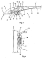
- La figure 5 est une vue en coupe longitudinale d'un système de plage arrière conforme à une variante du premier mode de réalisation de la présente invention, la tablette étant en position sortie ;
- La figure 6 est une vue en coupe longitudinale de la partie arrière d'un véhicule muni du système de plage arrière conforme à un second mode préféré de réalisation de la présente invention, la tablette étant en position sortie ;
- La figure 7 est une vue semblable à la figure 6, la tablette étant en position escamotée ; et
- La figure 8 est une vue semblable aux figures 6 et 7, la tablette étant dans une position intermédiaire entre ses positions sorties et escamotées.
- Figure 1 is a longitudinal sectional view of the rear portion of a vehicle equipped with the rear shelf system according to a first embodiment of the present invention, the tablet being in the extended position;
- Figure 2 is a view similar to Figure 1, the tablet being in the retracted position;
- Figure 3 is a cross-sectional view of the left end of the rear shelf system;
- Figure 4 is a top view of a detail of Figure 3;
- Figure 5 is a longitudinal sectional view of a rear shelf system according to a variant of the first embodiment of the present invention, the tablet being in the extended position;
- Figure 6 is a longitudinal sectional view of the rear portion of a vehicle equipped with the rear shelf system according to a second preferred embodiment of the present invention, the tablet being in the extended position;
- Figure 7 is a view similar to Figure 6, the tablet being in the retracted position; and
- Figure 8 is a view similar to Figures 6 and 7, the tablet being in an intermediate position between its extended and retracted positions.
Dans les présents exemples, comme on peut le voir aux figures 1 et 2, un véhicule comprend un coffre arrière 1 et un toit 2 rigide repliable.In the present examples, as can be seen in Figures 1 and 2, a vehicle comprises a
Le toit 2 est mobile entre une position déployée dans laquelle il recouvre l'habitacle du véhicule, et une position 5 pliée rangée dans laquelle il est plié dans le coffre arrière 1.The
Le véhicule comprend également un système de plage arrière 3 qui comporte une tablette 4,48. La tablette 4,48 est montée de façon mobile le long de deux rails 5,46 parallèles qui sont fixés à un élément support 6,45 du véhicule et qui s'étendent, de chaque côté de cet élément, sensiblement selon la direction longitudinale du véhicule. La tablette 4,48 est mobile entre une position sortie et une position escamotée. Quand elle est en position sortie, la tablette 4,48 recouvre l'espace qui est situé entre le bord avant 6a du capot 6 et le dossier 7a du siège 7 délimitant le coffre 1 (figure 1), et quand elle est en position escamotée, la tablette 4,48 libère cet espace (figure 2). Des moyens d'entraînement 8 sont adaptés à déplacer la tablette 4,48 de l'une à l'autre de ses positions.The vehicle also includes a
Selon l'invention, le système de plage arrière 3 comprend également des moyens d'appui 9,47 et les moyens d'entraînement 8.According to the invention, the
La tablette 4,48 est montée mobile sur les moyens d'appui 9,47 qui sont montés de façon mobile sur l'élément support 6,45 auquel les rails 5,46 sont fixés.The tablet 4.48 is movably mounted on the support means 9.47 which are mounted movably on the support element 6.45 to which the rails 5.46 are fixed.
Les moyens d'entraînement 8 comportent une première partie 10 et une deuxième partie 11. La première partie 10 est fixée à la tablette 4,48 et la deuxième partie 11 est fixée aux moyens d'appui 9,47. De ce fait, les moyens d'entraînement 8 génèrent le déplacement de la tablette 4,48 par rapport aux moyens d'appui 9,47. Ce mouvement relatif, le montage de la tablette 4,48 dans les rails 5,46 et le montage des moyens d'appui 9,47 sur l'élément support 6,45, permettent à la tablette 4,48 de se déplacer de l'une à l'autre de ses positions.The drive means 8 comprise a
La forme des rails 5,46 dans les directions longitudinale et verticale est adaptée à la cinématique prédéterminée de la tablette 4,48.The shape of the rails 5.46 in the longitudinal and vertical directions is adapted to the predetermined kinematics of the tablet 4.48.
Dans le premier mode de réalisation illustré aux figures 1 à 5, le capot 6 du coffre arrière 1 est l'élément support auquel sont fixés les rails 5 et sur lequel sont montés les moyens d'appui 9, la tablette 4 étant disposée sous le capot 6 quand elle est dans sa position escamotée.In the first embodiment illustrated in FIGS. 1 to 5, the
Dans l'exemple illustré aux figures 1 à 4, chaque rail 5 s'étend principalement selon la direction longitudinale et est sensiblement horizontal sur la plus grande partie de sa longueur, son extrémité avant 5a formant une courbe qui s'étend vers l'avant et vers le haut, ce qui permet à la tablette 4 de coulisser sous le capot 6 et, quand elle est à proximité de sa position sortie, c'est à dire quand son bord arrière 4b arrive à proximité du bord avant 6a du capot 6, de se déplacer vers le haut afin d'arriver sensiblement au niveau de ce dernier.In the example illustrated in Figures 1 to 4, each
Dans le présent exemple les rails 5 sont réalisés par emboutissage sur la face interne 6b du capot 6.In the present example the
Dans les présents exemples, les moyens d'appui 9 sont formés par deux glissières 9 parallèles qui sont rectilignes, s'étendent sensiblement selon la direction longitudinale de part et d'autre du véhicule du véhicule et sont montées de façon pivotante sur le capot 6 entre une position d'escamotage dans laquelle la tablette 4 est dans sa position escamotée, et une position de sortie dans laquelle la tablette 4 est dans sa position sortie. Chaque glissière 9 est montée pivotante sur le capot 6 autour d'un axe de pivotement 12 situé à l'extrémité arrière 9b de la glissière 9. Quelle que soit leur position, les glissières 9 s'étend principalement selon la direction longitudinale.In the present examples, the support means 9 are formed by two
La tablette 4 comporte deux éléments de guidage 13, chacun d'eux étant fixé à un bord transversal 4c correspondant de la tablette 4 par un bras de liaison 14. La surface sensiblement plane formant la tablette proprement dite, les éléments de guidage 13 et les bras de liaison 14 forment une tablette 4 sensiblement indéformable. Chaque élément de guidage 13 est adapté à assurer les liaisons mécaniques entre d'une part la tablette 4, et, d'autre part, la glissière 9 et le rail 5 correspondants.The
Dans l'exemple illustré à la figure 3, chaque élément de guidage 13 comprend un galet 15 par lequel la tablette 4 est montée coulissante le long de la glissière 9 correspondante, et un doigt 16 par lequel la tablette 4 est montée pivotante et coulissante le long du rail 5 correspondant.In the example illustrated in FIG. 3, each
Dans cet exemple, la première partie 10 des moyens d'entraînement 8 est formée par deux vis sans fin 10 et la deuxième partie 11 des moyens d'entraînement 8 est formée par deux crémaillères 11. Chacune des crémaillères 11 est montée le long d'une glissière 9 correspondante et s'étend, de ce fait, sensiblement selon la direction longitudinale du véhicule. Chaque vis sans fin 10 est logée dans une cavité 17 réalisée dans l'élément de guidage 13 correspondant et est montée en rotation dans cette cavité 17 autour d'un axe de rotation 18 s'étendant sensiblement selon la direction longitudinale du véhicule, de façon à coopérer avec la crémaillère 11 correspondante.In this example, the
Par ailleurs, un moteur 19 est fixé à la surface inférieure de la tablette 4 et des moyens de transmission 20, par exemple des flexibles, permettent de transmettre le mouvement de l'arbre du moteur 19 aux deux vis sans fin 10.Furthermore, a
De chaque côté du véhicule, le rail 5, la glissière 9 et l'élément de guidage 13 sont agencés de telle sorte que, quand un élément de guidage 13 est à proximité de l'extrémité arrière 9b de la glissière 9 correspondante, il est aussi à proximité de l'extrémité arrière 5b du rail 5 correspondant, la glissière 9 étant dans sa position d'escamotage et la tablette 4 étant dans sa position escamotée (figure 2). Et quand il est à proximité de l'extrémité avant 9a de la glissière 9 correspondante, il est aussi à proximité de l'extrémité avant 5a du rail 5 correspondant, la glissière 9 étant dans sa position de sortie et la tablette 4 étant dans sa position sortie (figure 1).On each side of the vehicle, the
Le mouvement de la tablette 4 de l'une à l'autre de ses positions, par rapport au capot 6, est généré de cette façon : chaque vis sans fin 10 est entraînée en rotation dans un sens ou dans l'autre par les moyens de transmission 20 et coopère avec la crémaillère 11 correspondante de façon à entraîner la translation de chaque galet 15 le long de la glissière 9 correspondante. Les glissières 9 étant reliées au capot 6 par leur axe de pivotement 12, leur translation par rapport au capot 6 est impossible, et, de ce fait, les deux galets 15 et les deux doigts 16 ont le même mouvement de translation par rapport au capot 6. Chaque doigt 16 pivote et coulisse le long du rail 5 correspondant de façon à imposer à la tablette 4 sa trajectoire, chaque galet 15 coulissant le long de la glissière 9 rectiligne correspondante qui pivote par rapport au capot 6 de façon à permettre le déplacement de la tablette 4 par rapport au capot 6.The movement of the
Dans l'exemple illustré à la figure 3, chaque élément de guidage 13 a une structure en forme de U inversé et possède une paroi de base 21 sensiblement horizontale, une paroi latérale externe 22 qui s'étend vers le bas à partir de la paroi de base 21 et qui est disposée du côté de la bordure latérale 23 du capot 6, et une paroi latérale interne 24 qui s'étend vers le bas à partir de la paroi de base 20 et qui est disposée du côté de la partie médiane du capot 6.In the example illustrated in FIG. 3, each
Le doigt 16 fait saillie transversalement vers l'extérieur par rapport à la paroi latérale externe 22 en direction de la bordure latérale 23 et pénètre dans le rail 5 correspondant qui est réalisé le long de cette bordure 23. Le galet 15 fait saillie transversalement vers l'extérieur par rapport à la paroi latérale interne 24 dans le logement 25 qui est délimité par la structure en U, et pénètre dans la glissière 9 qui a un mouvement de coulissement relatif dans ce logement 25. Cette conformation particulière de l'élément de guidage 13 rend le système de plage arrière 3 particulièrement compact.The
Dans l'exemple illustré à la figure 5, chaque glissière 9 est télescopique de façon à occuper le moins de place possible en position d'escamotage. Chaque glissière 9 comprend, à cet effet, un élément arrière 30, un élément avant 31 et des moyens de transmission 32.In the example illustrated in Figure 5, each
L'élément arrière 30 est monté pivotant sur le capot 6 autour de l'axe de pivotement 12 qui est situé à l'arrière 30b de l'élément arrière 30. L'élément avant 31 est monté coulissant le long de l'élément arrière 30, la tablette 4 étant montée coulissante le long de l'élément avant 31.The
Dans cet exemple, L'élément de guidage 13 comprend une réglette 33 par laquelle la tablette 4 est montée coulissante le long de l'élément avant 31.In this example, the
De chaque côté du système de plage arrière, la première partie 10 des moyens d'entraînement 8 est formé par un pignon 10 qui est monté sur la réglette 33 par un axe de rotation 34 transversal au véhicule et qui est engrené avec la crémaillère 11 qui s'étend le long de l'élément avant 31. Ainsi, la mise en rotation du pignon 10 entraîne le coulissement de la tablette 4 le long de l'élément avant 31.On each side of the rear shelf system, the
Les moyens de transmission 32 permettent de générer le coulissement de l'élément arrière 30 par rapport à l'élément avant 31. A cet effet, les moyens de transmission 32 comprennent, pour chaque glissière 9, deux câbles de liaison 35 et deux poulies de renvoi 36.The transmission means 32 make it possible to generate the sliding of the
Chaque câble de liaison 35 est fixé, par sa première extrémité 37, à la réglette 33, et par sa deuxième extrémité 38, à l'élément arrière 30. Chaque câble de liaison 35 est enroulé autour d'une poulie de renvoi 36 correspondante qui est montée sur une extrémité correspondante de l'élément avant 31 par un axe de rotation 39 transversal au véhicule. Par ailleurs, un pignon de transmission 40 qui est monté sur l'élément avant 31 par un axe de rotation 41 transversal au véhicule, est engrené avec une crémaillère de transmission 42 qui s'étend le long de l'élément arrière 30.Each connecting
Ainsi, la rotation du pignon 10 dans un sens ou dans l'autre entraîne directement le déplacement relatif de la tablette 4 par rapport à l'élément avant de glissière 31. Du fait de ce déplacement relatif, et de la présence des câbles de liaison 35, du pignon de transmission 40 et de la crémaillère de transmission 42, l'élément avant 31 coulisse par rapport à l'élément arrière 30 dans le même sens que celui du coulissement de la réglette 33 par rapport à l'élément avant 31.Thus, the rotation of the
Par une telle glissière 9, en utilisant des éléments de glissière ayant, dans la direction longitudinale, la même dimension que la tablette 4, l'ensemble formé par la tablette 4 et les glissière 9 n'occupe, dans la direction longitudinale, que la longueur de la tablette 4 quand celle-ci est dans sa position escamotée.By such a
Dans le second mode ici préféré de réalisation illustré aux figures 6 à 8, le châssis 45 du véhicule est l'élément support auquel sont fixés les rails 46 et sur lequel sont montés les moyens d'appui 47, la tablette 48 étant disposée derrière le dossier 7a du siège 7 délimitant le coffre 1 quand elle est dans sa position escamotée.In the second preferred mode of embodiment illustrated in FIGS. 6 to 8, the
Dans l'exemple illustré aux figures 6 à 8, chaque rail 46 s'étend principalement selon la direction verticale et est sensiblement vertical sur la plus grande partie de sa longueur, son extrémité supérieure 46a formant une courbe qui s'étend vers l'arrière et vers le haut, ce qui permet à la tablette 48 de coulisser derrière le dossier 7a, quand elle est à proximité de sa position sortie, c'est à dire quand son bord avant 48a arrive à proximité de l'extrémité supérieure arrière 7b du dossier 7a, de se déplacer vers l'arrière afin d'arriver sensiblement au niveau de ce dernier.In the example illustrated in Figures 6 to 8, each
Dans les présents exemples, les moyens d'appui 47 sont formés par deux glissières 47 parallèles qui sont rectilignes, s'étendent sensiblement selon la direction verticale de part et d'autre du véhicule du véhicule et sont montées de façon pivotante sur le châssis 45 entre une position d'escamotage dans laquelle la tablette 48 est dans sa position escamotée, et une position de sortie dans laquelle la tablette 48 est dans sa position sortie. Chaque glissière 47 est montée pivotante sur le châssis 45 autour d'un axe de pivotement 49 situé à l'extrémité inférieure 47b de la glissière 47. Quelle que soit leur position, les glissières 47 s'étend principalement selon la direction verticale.In the present examples, the support means 47 are formed by two
La tablette 48 comporte deux éléments de guidage (non représentés) similaires à ceux représentés à la figure 3 et qui permettent ainsi le déplacement de la tablette 48 par rapport au châssis 45. Ainsi, chaque élément de guidage est monté de façon coulissante le long de la glissière 47 correspondante, par l'intermédiaire d'un galet (similaire au galet 15, fig.3) et de façon pivotante et coulissante le long du rail 46 correspondant, par l'intermédiaire d'un doigt 61 (similaire au doigt 16, fig.3), de sorte que, quand il est à proximité de l'extrémité inférieure 47b de la glissière 47, il est aussi à proximité de l'extrémité inférieure 46b du rail 46, et quand il est à proximité de l'extrémité supérieure 47a de la glissière 47, il est aussi à proximité de l'extrémité supérieure 46a du rail 46.The
Du fait que, dans le second mode de réalisation, la tablette 48 est dans une position sensiblement verticale quand elle est dans sa position escamotée, les bras de liaison 50 supportant les éléments de guidage de la tablette 48, et la surface sensiblement plane 51 formant la tablette proprement dite sont articulés l'un à l'autre. Ainsi, quand la tablette 48 est dans sa position sortie, la surface sensiblement plane 51 est dans une position sensiblement horizontale permettant le recouvrement de l'espace qui est situé entre le bord avant 6a du capot 6 et le dossier 7a du siège 7 délimitant le coffre 1, et, quand la tablette 48 est dans sa position escamotée, la surface sensiblement plane 51 est dans une position sensiblement verticale permettant son rangement derrière le dossier 7a du siège 7 délimitant le coffre 1.Because, in the second embodiment, the
Cette articulation permet d'avoir un système de plage arrière 3 d'encombrement réduit.This articulation makes it possible to have a
Dans le présent exemple, la surface sensiblement plane 51 est reliée aux bras de liaison 50 de façon pivotante par un axe de rotation 52 qui est orienté selon la direction transversale au véhicule.In the present example, the substantially
Dans le présent exemple, l'articulation de la surface sensiblement plane 51 par rapport aux bras de liaison 50 est commandée par le déplacement des bras de liaison 50 par rapport au châssis 45. La surface sensiblement plane 51 comprend, de chaque côté, à l'extrémité avant de ses parois latérales, un ergot 53 qui est monté pivotant et coulissant le long d'une rampe 54 correspondante qui est solidaire du châssis 45 et qui s'étend sensiblement selon la direction verticale.In the present example, the articulation of the substantially
De ce fait, le déplacement des bras de liaison 50 par rapport au châssis 45, la liaison articulée de la surface sensiblement plane 51 aux bras de liaison 50, et le montage des ergots 53 dans les rampes 54 qui sont fixées au châssis 45, permettent à la surface sensiblement plane 51 de s'orienter correctement au fur at à mesure du déplacement des bras de laision 50 et de l'ensemble de la tablette 48.As a result, the displacement of the
La forme des rampes 54 dans les directions longitudinale et verticale est adaptée à la cinématique prédéterminée de la surface sensiblement plane 51. Dans le présent exemple, chaque rampe 54 s'étend principalement selon la direction verticale.The shape of the
Les rampes permettent de faire basculer la surface sensiblement plane 51 vers l'avant du véhicule quand la tablette 48 passe de sa position sortie à sa position escamotée.The ramps make it possible to tilt the substantially
Chaque rampe 54 est sensiblement verticale sur la plus grande partie de sa longueur, et son extrémité supérieure 54a forme une courbe qui s'étend vers l'arrière et se termine sensiblement horizontalement, ce qui permet à la surface sensiblement plane 51 d'être dans une position sensiblement horizontale quand la tablette 48 est dans sa position sortie.Each
Par ailleurs, dans le présent exemple, un moyen de rappel 55 (tel qu'un ressort) relié d'une part à la surface sensiblement plane 51 et d'autre part au bras de liaison correspondant 50 sollicite en permanence la surface sensiblement plane 51 dans sa position sensiblement horizontale.Furthermore, in the present example, a return means 55 (such as a spring) connected on the one hand to the substantially
L'utilisation d'un moyen de rappel 55 et le fait que le déplacement des bras de laision 50 par rapprot au châssis 45 entraîne l'orientation de la surface sensiblement plane 51 permet de limiter le nombre de pièces constitutives et donc d'avoir un système de plage arrière 3 d'encombrement particulièrement réduit.The use of a return means 55 and the fact that the displacement of the arms of the
Bien évidemment, les glissières pourraient être télescopiques, comme dans le cas illustré à la figure 5.Of course, the slides could be telescopic, as in the case illustrated in Figure 5.
Dans les exemples, le véhicule comporte des moyens de commande de la synchronisation (non représentés) des mouvements de la tablette 4,48 et du toit 2 de sorte que, quand le toit 2 est dans ses positions déployée ou pliée rangée, la tablette 4,48 est respectivement dans ses positions escamotée ou sortie.In the examples, the vehicle comprises means for controlling the synchronization (not shown) of the movements of the plate 4.48 and the
Le système de plage arrière peut comprendre une seconde tablette (non illustrée) qui serait montée mobile entre une position déployée dans laquelle elle recouvre l'espace situé entre le bord arrière du toit en position déployée et le dossier du siège délimitant le coffre, et une position escamotée dans laquelle elle est disposée le long de la lunette arrière et libère cet espace. Les moyens de commande de la synchronisation des mouvements sont tels que, quand le toit est dans sa position déployée, la première tablette est dans sa position escamotée et la seconde tablette est dans sa position déployée, et, quand le toit est dans sa position pliée rangée, la première tablette est dans sa position sortie, et la seconde tablette est dans sa position escamotée.The rear shelf system may comprise a second shelf (not shown) which is movably mounted between an extended position in which it covers the space between the rear edge of the roof in the deployed position and the seat back defining the trunk, and a retracted position in which it is arranged along the rear window and releases this space. The control means of the synchronization of the movements are such that, when the roof is in its deployed position, the first tablet is in its retracted position and the second shelf is in its deployed position, and when the roof is in its folded row position, the first shelf is in its extended position, and the second shelf is in its retracted position.
Le système de plage arrière conforme à la présente invention forme un module indépendant pouvant être monté sur un véhicule.The rear shelf system according to the present invention forms an independent module mountable on a vehicle.
Bien évidemment, le système de plage arrière n'est pas limité au mode de réalisation particulier décrit en détail.Of course, the rear shelf system is not limited to the particular embodiment described in detail.
Par exemple, les rails 5 pourraient être fixés à la face interne 6b du capot 6, par exemple vissage ou par soudage, et faire, de ce fait, partie du module de plage arrière.For example, the
Par exemple, les moyens de déplacement pourraient être formés par des vérins dont la tige serait solidaire de la tablette 4,48 et le cylindre serait solidaire des moyens d'appui 9,47, ou inversement.For example, the displacement means could be formed by cylinders whose rod would be integral with the tablet 4.48 and the cylinder would be integral with the support means 9.47, or vice versa.
Par exemple, dans le second mode de réalisation, les rails pourraient être fixés au siège (au dossier) délimitant le coffre arrière, et non pas au châssis.For example, in the second embodiment, the rails could be attached to the seat (backrest) delimiting the trunk, not the chassis.
Claims (26)
- Shelf assembly (3) for a vehicle, comprising a shelf (4, 48) adapted to be mounted, in a movable manner, along two tracks (5, 46) between, on one hand, a deployed position in which it covers an area located between the front edge (6a) of the hood (6) of the rear boot (1) of the vehicle and a backrest (7a) of a seat (7) delimiting a boot (1), and on the other hand, a retracted position in which it uncovers this area, each track (5, 46) being fixed to a support element (6, 45) of the vehicle and substantially extending along the longitudinal direction of the vehicle, driving means (8), which comprise a first part (10) fixed to the shelf (4, 48) and a second part (11) engaging the first part (10), being adapted to displace the shelf (4, 48) from one of its positions to the other one, characterised in that it comprises supporting means (9, 47) onto which the shelf (4, 48) is mounted in a movable manner, and which are adapted to be mounted in a movable manner onto the support element (6, 45), and in that the second part (11) of the driving means (8) is fixed to the supporting means (9, 47), the displacement of the shelf (4, 48) with respect to the supporting means (9, 47) compelling the displacement of the shelf (4, 48) from one of its positions to the other one and the displacement of the supporting means (9, 47) with respect to the support element (6, 45).
- Shelf assembly (3) set forth in claim 1, characterised in that the supporting means (9, 47) are formed by two sliders (9, 47) which are adapted to extend on either side of the vehicle and which are swivel mounted onto the support element (6, 45), the shelf (4, 48) being slide mounted along the sliders (9, 47) and both swivel and slide mounted along the tracks (5, 46).
- Shelf assembly set forth in claim 1 or 2, characterised in that the vehicle being provided with a rigid roof (2) movable between a deployed position in which it covers the vehicle passenger compartment and a stored position in which it is folded inside the boot (1), the shelf (4, 48) extends, in its deployed position, as far as said area which is located between the backrest (7a) of the seat (7) and the front edge (6a) of the said hood (6) and which is covered by the rigid roof (2) when in its deployed position.
- Shelf assembly (3) set forth in claim 2 or 3, characterised in that each slider (9, 47) is telescopic.
- Shelf assembly (3) set forth in one of claims 2 to 4, characterised in that the shelf (4, 48) comprises two guiding elements (13), each guiding element (13) being slide mounted along the corresponding slider (9, 47) and in a swivel and slide manner along the corresponding track (5, 46).
- Shelf assembly (3) set forth in claim 5, characterised in that the driving means (8) comprise two racks (11) and two worms (10), each rack (11) being mounted along the corresponding slider (9, 47), and each worm (10) engaging the corresponding rack (11) and being rotary mounted onto the corresponding guiding element (13) about an axis of rotation (18) extending substantially along the longitudinal direction.
- Shelf assembly (3) set forth in claim 5 or 6, characterised in that each guiding element (13) has an inverted U-shaped structure and has a base wall (21), an external side wall (22) extending from the base wall (21) and placed near the side rim (23) of the support element (6, 45), and an internal side wall (24) extending from the base wall (20) and placed near the median part of the support element (6, 45).
- Shelf assembly (3) set forth in any of claims 5 to 7, characterised in that each guiding element (13) comprises a roller (15) slide mounted along the corresponding slider (9, 47), and a cam pin (16) swivel and slide mounted along the corresponding track (5, 46).
- Shelf assembly (3) set forth in claims 7 and 8, characterised in that, for each guiding element (13), the cam pin (16) transversally projects outwards with respect to the external side wall (22) in the direction of the side rim (23), and the roller (15) transversally projects outwards with respect to the internal side wall (24) into the housing (25) delimited by the U-shaped structure.
- Shelf assembly (3) set forth in any of claims 7 to 9, characterised in that each slider (9, 47) is placed in the housing (25) created by the U-shaped structure and has a relative sliding movement in this housing (25).
- Shelf assembly (3) set forth in any of claims 1 to 10, characterised in that the support element (6) is formed by the hood (6) of the rear boot (1), the tracks (5) and the supporting means (9) being configured so that the shelf (4) is adapted to being placed under the hood (6) when in its retracted position.
- Shelf assembly (3) set forth in claim 11 depending on claim 2, characterised in that each slider (9) is swivel mounted onto the hood (6) at its rear end (9b) and is adapted to extend along a substantially horizontal direction.
- Shelf assembly (3) set forth in claim 11 or 12 depending on claim 5, characterised in that when the guiding element (13) is close to the rear end (9b) of the slider (9), it is also close to the rear end (5b) of the track (5), and when it is close to the front end (9a) of the slider (9), it is also close to the front end (5a) of the track (5).
- Shelf assembly (3) set forth in any of claims 1 to 10, characterised in that the support element (45) is formed by the frame (45) of the vehicle, the tracks (46) and the supporting means (47) being configured so that the shelf (48) is adapted to be arranged behind the backrest (7a) of the seat (7) delimiting the boot (1) when in its retracted position.
- Shelf assembly (3) set forth in claim 14 depending on claim 2, characterised in that each slider (47) is swivel mounted onto the frame (45) at its rear end (47b) and is adapted to extend along a substantially vertical direction.
- Shelf assembly (3) set forth in claim 14 or 15 depending on claim 5, characterised in that when the guiding element (13) is close to the lower end (47b) of the slider (47), it is also close to the lower end (46b) of the track (46), and when it is close to the upper end (47a) of the slider (47), it is also close to the upper end (46a) of the track (46).
- Shelf assembly (3) set forth in any of claims 1 to 16, characterised in that the shelf (4) forms a substantially non-malleable unit.
- Shelf assembly (3) set forth in any of claims 1 to 16 depending on claim 5, characterised in that the shelf (48) comprises a substantially plane surface (51) defining the shelf and two connecting arms (50) which support the guiding elements (13) and which are articulated with respect to the substantially plane surface (51) so that, when the shelf (48) is in its deployed position, the substantially plane surface (51) is in a substantially horizontal position and, when the shelf (48) is in its retracted position, the substantially plane surface (51) is in an inclined position with respect to the horizontal, preferably in a substantially vertical position.
- Shelf assembly (3) set forth in claim 18, characterised in that the substantially plane surface (51) is linked, in a swivel manner, to the connecting arms (50) along an axis of rotation (52) extending along the transverse direction of the vehicle.
- Shelf assembly (3) set forth in claims 18 or 19, characterised in that a means for retracting (55) constantly urges the substantially plane surface (51) towards its substantially horizontal position.
- Shelf assembly (3) set forth in any of claims 18 to 20 depending on claim 14, characterised in that the articulating of the substantially plane surface (51) with respect to the connecting arms (50) is controlled by the displacement of the correcting arms (50) with respect to the frame (45).
- Shelf assembly (3) set forth in claim 21, characterised in that the substantially plane surface (51) comprises, on each side, at the front end of its side walls, a stub (53) which is swivel and slide mounted along a corresponding ramp (54) which is fixed to the frame (45) and which extends substantially along the vertical direction.
- Shelf assembly set forth in any of the preceding claims, characterised in that the vehicle being provided with a rigid roof movable between a deployed position in which it covers the vehicle passenger compartment and a stored position in which it is folded inside the boot (1), when the roof (2) is in its deployed position, the shelf is in its retracted position and situated under the hood (6).
- Shelf assembly set forth in claim 3 or 23, characterised in that when the roof ( 2) is in its deployed position, the shelf (4, 48) is in its retracted position, and when the roof is in its stored folded position, said shelf is in its deployed position.
- Shelf assembly set forth in claim 1 or 2, characterised in that- the vehicle being provided with a rigid roof (2) movable between a deployed position in which it covers the vehicle passenger compartment and a stored position in which it is folded inside the boot (1), said assembly comprises a second shelf movable between a deployed position in which it covers the area located between the rear edge of the roof, which is then in its deployed position, and the backrest of the seat delimiting the boot, and a retracted position in which it is placed along the rear window and uncovers this area,- when the roof (2) is in its deployed position, the shelf (4, 48) is in its retracted position and the second shelf is in its deployed position,- and, when the roof is in its folded stored position, the shelf (4, 48) is in its deployed position, and the second shelf is in its retracted position.
- Vehicle provided with the shelf assembly set forth in any one of the preceding claims.
Applications Claiming Priority (5)
| Application Number | Priority Date | Filing Date | Title |
|---|---|---|---|
| FR0302490A FR2851753B1 (en) | 2003-02-28 | 2003-02-28 | VEHICLE REAR BEARING SYSTEM |
| FR0302490 | 2003-02-28 | ||
| FR0311378A FR2851751B1 (en) | 2003-02-28 | 2003-09-29 | VEHICLE REAR BEARING SYSTEM |
| FR0311378 | 2003-09-29 | ||
| PCT/FR2004/000380 WO2004078520A2 (en) | 2003-02-28 | 2004-02-18 | Package shelf for a convertible |
Publications (2)
| Publication Number | Publication Date |
|---|---|
| EP1599359A2 EP1599359A2 (en) | 2005-11-30 |
| EP1599359B1 true EP1599359B1 (en) | 2006-09-20 |
Family
ID=32852334
Family Applications (1)
| Application Number | Title | Priority Date | Filing Date |
|---|---|---|---|
| EP04712081A Expired - Lifetime EP1599359B1 (en) | 2003-02-28 | 2004-02-18 | Package shelf for a convertible |
Country Status (8)
| Country | Link |
|---|---|
| US (1) | US7121602B2 (en) |
| EP (1) | EP1599359B1 (en) |
| JP (1) | JP2006519134A (en) |
| KR (1) | KR20060030464A (en) |
| AT (1) | ATE340100T1 (en) |
| DE (1) | DE602004002463T2 (en) |
| FR (1) | FR2851751B1 (en) |
| WO (1) | WO2004078520A2 (en) |
Families Citing this family (6)
| Publication number | Priority date | Publication date | Assignee | Title |
|---|---|---|---|---|
| DE102004003020A1 (en) * | 2004-01-20 | 2005-08-11 | Wilhelm Karmann Gmbh | Convertible car |
| US20060255619A1 (en) * | 2005-05-16 | 2006-11-16 | Dickie Robert B | Retractable hard top for a four door vehicle |
| DE102006054397A1 (en) | 2006-11-18 | 2008-05-21 | Wilhelm Karmann Gmbh | Cabriolet vehicle with a foldable under a top compartment lid, convertible top compartment module and method for operating a convertible top lid |
| FR2910386B1 (en) | 2006-12-22 | 2009-02-06 | Heuliez Sa | MOBILE RANGE VEHICLE WITH SOFT CONTACT ORGAN. |
| DE102009000845A1 (en) * | 2009-02-13 | 2010-08-19 | BSH Bosch und Siemens Hausgeräte GmbH | Refrigeration unit with height-adjustable refrigerated goods storage |
| US9016750B2 (en) * | 2010-10-01 | 2015-04-28 | Cap-Pack Truck Products Llc | Vehicular storage system |
Family Cites Families (23)
| Publication number | Priority date | Publication date | Assignee | Title |
|---|---|---|---|---|
| US2934248A (en) * | 1956-06-25 | 1960-04-26 | Jack A Lown | Station wagon platform accessory |
| US4198091A (en) * | 1978-07-13 | 1980-04-15 | Appleton Arthur I | Vehicle with space tradeable between rear seat and trunk |
| DE3623468A1 (en) * | 1985-07-13 | 1987-01-22 | Nissan Motor | Motor vehicle with a hard-top body and removable top and a method for removing and reattaching a hard top to a motor vehicle |
| JPH035237A (en) * | 1989-05-31 | 1991-01-11 | Mazda Motor Corp | Roof housing structure of opencar |
| US5209544A (en) * | 1990-09-21 | 1993-05-11 | Fiat Auto S.P.A. | Convertible automobile |
| FR2681292A1 (en) * | 1991-09-18 | 1993-03-19 | Peugeot | Layout of a convertible vehicle (vehicle which can be converted into an open-top vehicle) |
| JPH0858387A (en) * | 1994-08-26 | 1996-03-05 | Kanto Auto Works Ltd | Awning storage structure for open car |
| DE29721430U1 (en) * | 1997-12-04 | 1999-04-01 | Edscha Cabrio-Verdecksysteme GmbH & Co., 94491 Hengersberg | Multi-part convertible top compartment lid for convertible vehicles |
| DE29802871U1 (en) * | 1998-02-19 | 1999-06-17 | Edscha Cabrio-Verdecksysteme GmbH & Co., 94491 Hengersberg | Cover for convertible top boxes |
| DE29812164U1 (en) * | 1998-07-08 | 1999-05-06 | Wilhelm Karmann GmbH, 49084 Osnabrück | Cabriolet vehicle with a convertible top compartment |
| US6217104B1 (en) * | 1999-06-16 | 2001-04-17 | Cts Fahrzeug Dachsysteme Gmbh | Retractable hard top module |
| JP4292354B2 (en) * | 1999-10-19 | 2009-07-08 | アイシン精機株式会社 | Package tray for vehicles |
| JP3523816B2 (en) * | 1999-10-19 | 2004-04-26 | アイシン精機株式会社 | Luggage panel opening and closing device |
| US6283533B1 (en) * | 1999-11-29 | 2001-09-04 | Lawrence E. Gavin | Boot cover apparatus |
| FI109777B (en) * | 2000-03-23 | 2002-10-15 | Valmet Automotive Oy | Cover for storage of a roof of an open car and open car |
| FR2809057B1 (en) * | 2000-05-17 | 2002-10-11 | Peugeot Citroen Automobiles Sa | FOLDABLE ROOF VEHICLE TRUNK ARRANGEMENT |
| DE10039683B4 (en) * | 2000-08-14 | 2005-02-24 | Wilhelm Karmann Gmbh | Convertible car |
| DE10134370B4 (en) * | 2001-07-14 | 2006-01-05 | Daimlerchrysler Ag | Covering device for a convertible top compartment |
| DE10135223A1 (en) * | 2001-07-24 | 2003-02-27 | Cts Fahrzeug Dachsysteme Gmbh | Cover for a top compartment |
| FR2834953B1 (en) * | 2002-01-21 | 2004-06-04 | France Design | DEVICE FOR CONTROLLING A REAR SHELF OF A MOTOR VEHICLE |
| FR2839474B1 (en) * | 2002-05-13 | 2005-01-14 | France Design | REAR BEACH OF VEHICLE |
| FR2842467B1 (en) * | 2002-07-19 | 2008-07-18 | France Design | REAR RANGE SYSTEM FOR DISABLED VEHICLE WITH FOLDING RIGID ROOF |
| DE10245361B4 (en) * | 2002-09-28 | 2005-04-14 | Wilhelm Karmann Gmbh | Convertible vehicle with retractable folding top |
-
2003
- 2003-09-29 FR FR0311378A patent/FR2851751B1/en not_active Expired - Fee Related
-
2004
- 2004-02-18 US US10/517,127 patent/US7121602B2/en not_active Expired - Fee Related
- 2004-02-18 WO PCT/FR2004/000380 patent/WO2004078520A2/en not_active Ceased
- 2004-02-18 DE DE602004002463T patent/DE602004002463T2/en not_active Expired - Lifetime
- 2004-02-18 EP EP04712081A patent/EP1599359B1/en not_active Expired - Lifetime
- 2004-02-18 JP JP2006505674A patent/JP2006519134A/en active Pending
- 2004-02-18 KR KR1020057012574A patent/KR20060030464A/en not_active Abandoned
- 2004-02-18 AT AT04712081T patent/ATE340100T1/en not_active IP Right Cessation
Also Published As
| Publication number | Publication date |
|---|---|
| WO2004078520A2 (en) | 2004-09-16 |
| FR2851751A1 (en) | 2004-09-03 |
| WO2004078520A3 (en) | 2004-10-14 |
| US7121602B2 (en) | 2006-10-17 |
| KR20060030464A (en) | 2006-04-10 |
| EP1599359A2 (en) | 2005-11-30 |
| DE602004002463T2 (en) | 2007-09-20 |
| US20060091686A1 (en) | 2006-05-04 |
| DE602004002463D1 (en) | 2006-11-02 |
| ATE340100T1 (en) | 2006-10-15 |
| FR2851751B1 (en) | 2006-06-23 |
| JP2006519134A (en) | 2006-08-24 |
Similar Documents
| Publication | Publication Date | Title |
|---|---|---|
| WO2001045976A1 (en) | Roof that can be retracted into the trunk of a vehicle | |
| EP1597104B1 (en) | Lock system for a convertible vehicle roof | |
| EP1599359B1 (en) | Package shelf for a convertible | |
| FR2853868A1 (en) | RETRACTABLE REAR BEACH SYSTEM FOR FOLDABLE ROOF DISCOVERABLE VEHICLE | |
| EP1597101B1 (en) | Retractable roof for a vehicle | |
| EP1711361B1 (en) | Roof retractable in the trunk of a vehicle comprising lateral displaceable elements | |
| EP1644212A2 (en) | Vehicle with retractable open top and method for stowing same, with a horizontal tilting system | |
| EP1320467A1 (en) | Motor vehicle retractable roof and in particular pick-up equipped with same | |
| EP1467883A1 (en) | Rear shelf for motor vehicle equipped with a folding roof | |
| EP1467882A1 (en) | Actuator for a rear panel on a motor vehicle | |
| FR2853601A1 (en) | VEHICLE REAR BEACH SYSTEM | |
| EP1633585B1 (en) | Vehicle comprising a vertically folding sun roof | |
| FR2608528A1 (en) | SUNROOF FOR VEHICLES | |
| FR2851753A1 (en) | VEHICLE REAR BEACH SYSTEM | |
| EP1556239B1 (en) | Modular assembly for vehicle with retractable roof and corresponding vehicle | |
| FR2828838A1 (en) | Sedan convertible into pick up comprises compartment delimited by floor, partly retractable roof, rear door with window and panel, roof formed by transverse slats able to move rearwards | |
| FR2880851A1 (en) | RETRACTABLE FOOTBOARD FOR A SLIDING DOOR OF A MOTOR VEHICLE AND A CORRESPONDING VEHICLE. | |
| WO2005075230A1 (en) | Motor vehicle folding roof | |
| FR2845950A1 (en) | CONVERTIBLE ROOF FOR VEHICLE | |
| FR2854353A1 (en) | RETRACTABLE ROOF ELEMENT AND VEHICLE THUS EQUIPPED | |
| WO2004091952A2 (en) | Removable rigid roof mechanism for a motor vehicle | |
| FR2834950A1 (en) | DEVICE FOR CONTROLLING A REAR SHELF OF A MOTOR VEHICLE | |
| FR2872456A1 (en) | RIGID FOLDING ROOF | |
| WO2005012017A2 (en) | Folding roof rear element and vehicle equipped therewith | |
| WO2005075229A1 (en) | Motor vehicle folding roof |
Legal Events
| Date | Code | Title | Description |
|---|---|---|---|
| PUAI | Public reference made under article 153(3) epc to a published international application that has entered the european phase |
Free format text: ORIGINAL CODE: 0009012 |
|
| 17P | Request for examination filed |
Effective date: 20050701 |
|
| AK | Designated contracting states |
Kind code of ref document: A2 Designated state(s): AT BE BG CH CY CZ DE DK EE ES FI FR GB GR HU IE IT LI LU MC NL PT RO SE SI SK TR |
|
| AX | Request for extension of the european patent |
Extension state: AL LT LV MK |
|
| 111L | Licence recorded |
Free format text: 0100 FRANCE DESIGN Effective date: 20051227 |
|
| GRAP | Despatch of communication of intention to grant a patent |
Free format text: ORIGINAL CODE: EPIDOSNIGR1 |
|
| DAX | Request for extension of the european patent (deleted) | ||
| GRAS | Grant fee paid |
Free format text: ORIGINAL CODE: EPIDOSNIGR3 |
|
| GRAA | (expected) grant |
Free format text: ORIGINAL CODE: 0009210 |
|
| AK | Designated contracting states |
Kind code of ref document: B1 Designated state(s): AT BE BG CH CY CZ DE DK EE ES FI FR GB GR HU IE IT LI LU MC NL PT RO SE SI SK TR |
|
| PG25 | Lapsed in a contracting state [announced via postgrant information from national office to epo] |
Ref country code: FI Free format text: LAPSE BECAUSE OF FAILURE TO SUBMIT A TRANSLATION OF THE DESCRIPTION OR TO PAY THE FEE WITHIN THE PRESCRIBED TIME-LIMIT Effective date: 20060920 Ref country code: IE Free format text: LAPSE BECAUSE OF FAILURE TO SUBMIT A TRANSLATION OF THE DESCRIPTION OR TO PAY THE FEE WITHIN THE PRESCRIBED TIME-LIMIT Effective date: 20060920 Ref country code: SI Free format text: LAPSE BECAUSE OF FAILURE TO SUBMIT A TRANSLATION OF THE DESCRIPTION OR TO PAY THE FEE WITHIN THE PRESCRIBED TIME-LIMIT Effective date: 20060920 Ref country code: AT Free format text: LAPSE BECAUSE OF FAILURE TO SUBMIT A TRANSLATION OF THE DESCRIPTION OR TO PAY THE FEE WITHIN THE PRESCRIBED TIME-LIMIT Effective date: 20060920 Ref country code: NL Free format text: LAPSE BECAUSE OF FAILURE TO SUBMIT A TRANSLATION OF THE DESCRIPTION OR TO PAY THE FEE WITHIN THE PRESCRIBED TIME-LIMIT Effective date: 20060920 Ref country code: SK Free format text: LAPSE BECAUSE OF FAILURE TO SUBMIT A TRANSLATION OF THE DESCRIPTION OR TO PAY THE FEE WITHIN THE PRESCRIBED TIME-LIMIT Effective date: 20060920 Ref country code: CZ Free format text: LAPSE BECAUSE OF FAILURE TO SUBMIT A TRANSLATION OF THE DESCRIPTION OR TO PAY THE FEE WITHIN THE PRESCRIBED TIME-LIMIT Effective date: 20060920 Ref country code: RO Free format text: LAPSE BECAUSE OF FAILURE TO SUBMIT A TRANSLATION OF THE DESCRIPTION OR TO PAY THE FEE WITHIN THE PRESCRIBED TIME-LIMIT Effective date: 20060920 Ref country code: IT Free format text: LAPSE BECAUSE OF FAILURE TO SUBMIT A TRANSLATION OF THE DESCRIPTION OR TO PAY THE FEE WITHIN THE PRESCRIBED TIME-LIMIT;WARNING: LAPSES OF ITALIAN PATENTS WITH EFFECTIVE DATE BEFORE 2007 MAY HAVE OCCURRED AT ANY TIME BEFORE 2007. THE CORRECT EFFECTIVE DATE MAY BE DIFFERENT FROM THE ONE RECORDED. Effective date: 20060920 |
|
| REG | Reference to a national code |
Ref country code: GB Ref legal event code: FG4D Free format text: NOT ENGLISH |
|
| REG | Reference to a national code |
Ref country code: CH Ref legal event code: EP |
|
| RAP2 | Party data changed (patent owner data changed or rights of a patent transferred) |
Owner name: SOCIETE EUROPEENNE DE BREVETS AUTOMOBILES - SEBA |
|
| REG | Reference to a national code |
Ref country code: IE Ref legal event code: FG4D Free format text: LANGUAGE OF EP DOCUMENT: FRENCH |
|
| REF | Corresponds to: |
Ref document number: 602004002463 Country of ref document: DE Date of ref document: 20061102 Kind code of ref document: P |
|
| PG25 | Lapsed in a contracting state [announced via postgrant information from national office to epo] |
Ref country code: DK Free format text: LAPSE BECAUSE OF FAILURE TO SUBMIT A TRANSLATION OF THE DESCRIPTION OR TO PAY THE FEE WITHIN THE PRESCRIBED TIME-LIMIT Effective date: 20061220 Ref country code: SE Free format text: LAPSE BECAUSE OF FAILURE TO SUBMIT A TRANSLATION OF THE DESCRIPTION OR TO PAY THE FEE WITHIN THE PRESCRIBED TIME-LIMIT Effective date: 20061220 Ref country code: BG Free format text: LAPSE BECAUSE OF FAILURE TO SUBMIT A TRANSLATION OF THE DESCRIPTION OR TO PAY THE FEE WITHIN THE PRESCRIBED TIME-LIMIT Effective date: 20061220 |
|
| PG25 | Lapsed in a contracting state [announced via postgrant information from national office to epo] |
Ref country code: ES Free format text: LAPSE BECAUSE OF FAILURE TO SUBMIT A TRANSLATION OF THE DESCRIPTION OR TO PAY THE FEE WITHIN THE PRESCRIBED TIME-LIMIT Effective date: 20061231 |
|
| NLT2 | Nl: modifications (of names), taken from the european patent patent bulletin |
Owner name: SOCIETE EUROPEENNE DE BREVETS AUTOMOBILES - SEBA Effective date: 20061025 |
|
| PG25 | Lapsed in a contracting state [announced via postgrant information from national office to epo] |
Ref country code: MC Free format text: LAPSE BECAUSE OF NON-PAYMENT OF DUE FEES Effective date: 20070228 |
|
| NLV1 | Nl: lapsed or annulled due to failure to fulfill the requirements of art. 29p and 29m of the patents act | ||
| PG25 | Lapsed in a contracting state [announced via postgrant information from national office to epo] |
Ref country code: PT Free format text: LAPSE BECAUSE OF FAILURE TO SUBMIT A TRANSLATION OF THE DESCRIPTION OR TO PAY THE FEE WITHIN THE PRESCRIBED TIME-LIMIT Effective date: 20070312 |
|
| GBT | Gb: translation of ep patent filed (gb section 77(6)(a)/1977) |
Effective date: 20070215 |
|
| RAP2 | Party data changed (patent owner data changed or rights of a patent transferred) |
Owner name: SOCIETE EUROPEENNE DE BREVETS AUTOMOBILES |
|
| REG | Reference to a national code |
Ref country code: IE Ref legal event code: FD4D |
|
| PLBE | No opposition filed within time limit |
Free format text: ORIGINAL CODE: 0009261 |
|
| STAA | Information on the status of an ep patent application or granted ep patent |
Free format text: STATUS: NO OPPOSITION FILED WITHIN TIME LIMIT |
|
| 26N | No opposition filed |
Effective date: 20070621 |
|
| BERE | Be: lapsed |
Owner name: SOC. EUROPEENNE DES BREVETS AUTOMOBILES Effective date: 20070228 |
|
| PG25 | Lapsed in a contracting state [announced via postgrant information from national office to epo] |
Ref country code: BE Free format text: LAPSE BECAUSE OF NON-PAYMENT OF DUE FEES Effective date: 20070228 |
|
| PG25 | Lapsed in a contracting state [announced via postgrant information from national office to epo] |
Ref country code: GR Free format text: LAPSE BECAUSE OF FAILURE TO SUBMIT A TRANSLATION OF THE DESCRIPTION OR TO PAY THE FEE WITHIN THE PRESCRIBED TIME-LIMIT Effective date: 20061221 |
|
| PG25 | Lapsed in a contracting state [announced via postgrant information from national office to epo] |
Ref country code: EE Free format text: LAPSE BECAUSE OF FAILURE TO SUBMIT A TRANSLATION OF THE DESCRIPTION OR TO PAY THE FEE WITHIN THE PRESCRIBED TIME-LIMIT Effective date: 20060920 |
|
| REG | Reference to a national code |
Ref country code: CH Ref legal event code: PL |
|
| PG25 | Lapsed in a contracting state [announced via postgrant information from national office to epo] |
Ref country code: CH Free format text: LAPSE BECAUSE OF NON-PAYMENT OF DUE FEES Effective date: 20080229 Ref country code: LI Free format text: LAPSE BECAUSE OF NON-PAYMENT OF DUE FEES Effective date: 20080229 |
|
| PG25 | Lapsed in a contracting state [announced via postgrant information from national office to epo] |
Ref country code: LU Free format text: LAPSE BECAUSE OF NON-PAYMENT OF DUE FEES Effective date: 20070218 Ref country code: CY Free format text: LAPSE BECAUSE OF FAILURE TO SUBMIT A TRANSLATION OF THE DESCRIPTION OR TO PAY THE FEE WITHIN THE PRESCRIBED TIME-LIMIT Effective date: 20060920 |
|
| PG25 | Lapsed in a contracting state [announced via postgrant information from national office to epo] |
Ref country code: HU Free format text: LAPSE BECAUSE OF FAILURE TO SUBMIT A TRANSLATION OF THE DESCRIPTION OR TO PAY THE FEE WITHIN THE PRESCRIBED TIME-LIMIT Effective date: 20070321 Ref country code: TR Free format text: LAPSE BECAUSE OF FAILURE TO SUBMIT A TRANSLATION OF THE DESCRIPTION OR TO PAY THE FEE WITHIN THE PRESCRIBED TIME-LIMIT Effective date: 20060920 |
|
| PGFP | Annual fee paid to national office [announced via postgrant information from national office to epo] |
Ref country code: IT Payment date: 20120213 Year of fee payment: 9 |
|
| PGFP | Annual fee paid to national office [announced via postgrant information from national office to epo] |
Ref country code: GB Payment date: 20130213 Year of fee payment: 10 Ref country code: DE Payment date: 20130213 Year of fee payment: 10 |
|
| PGFP | Annual fee paid to national office [announced via postgrant information from national office to epo] |
Ref country code: FR Payment date: 20130717 Year of fee payment: 10 |
|
| REG | Reference to a national code |
Ref country code: DE Ref legal event code: R119 Ref document number: 602004002463 Country of ref document: DE |
|
| GBPC | Gb: european patent ceased through non-payment of renewal fee |
Effective date: 20140218 |
|
| REG | Reference to a national code |
Ref country code: FR Ref legal event code: ST Effective date: 20141031 |
|
| REG | Reference to a national code |
Ref country code: DE Ref legal event code: R119 Ref document number: 602004002463 Country of ref document: DE Effective date: 20140902 |
|
| PG25 | Lapsed in a contracting state [announced via postgrant information from national office to epo] |
Ref country code: DE Free format text: LAPSE BECAUSE OF NON-PAYMENT OF DUE FEES Effective date: 20140902 Ref country code: GB Free format text: LAPSE BECAUSE OF NON-PAYMENT OF DUE FEES Effective date: 20140218 Ref country code: FR Free format text: LAPSE BECAUSE OF NON-PAYMENT OF DUE FEES Effective date: 20140228 |
|
| PG25 | Lapsed in a contracting state [announced via postgrant information from national office to epo] |
Ref country code: IT Free format text: LAPSE BECAUSE OF NON-PAYMENT OF DUE FEES Effective date: 20140218 |
|
| REG | Reference to a national code |
Ref country code: CH Ref legal event code: PK Free format text: COMPLEMENT D'ENREGISTREMENT DE LICENCE: LICENCE NON-EXCLUSIVE |