EP1556239B1 - Modulare montageeinheit für ein kfz mit faltbarem dach und ein kfz mit solch einer einheit - Google Patents
Modulare montageeinheit für ein kfz mit faltbarem dach und ein kfz mit solch einer einheit Download PDFInfo
- Publication number
- EP1556239B1 EP1556239B1 EP03767858A EP03767858A EP1556239B1 EP 1556239 B1 EP1556239 B1 EP 1556239B1 EP 03767858 A EP03767858 A EP 03767858A EP 03767858 A EP03767858 A EP 03767858A EP 1556239 B1 EP1556239 B1 EP 1556239B1
- Authority
- EP
- European Patent Office
- Prior art keywords
- seat back
- vehicle
- roof
- shelf
- central shelf
- Prior art date
- Legal status (The legal status is an assumption and is not a legal conclusion. Google has not performed a legal analysis and makes no representation as to the accuracy of the status listed.)
- Expired - Lifetime
Links
Images


Classifications
-
- B—PERFORMING OPERATIONS; TRANSPORTING
- B60—VEHICLES IN GENERAL
- B60J—WINDOWS, WINDSCREENS, NON-FIXED ROOFS, DOORS, OR SIMILAR DEVICES FOR VEHICLES; REMOVABLE EXTERNAL PROTECTIVE COVERINGS SPECIALLY ADAPTED FOR VEHICLES
- B60J7/00—Non-fixed roofs; Roofs with movable panels, e.g. rotary sunroofs
- B60J7/20—Vehicle storage compartments for roof parts or for collapsible flexible tops
- B60J7/202—Vehicle storage compartments for roof parts or for collapsible flexible tops being characterised by moveable cover parts for closing the gap between boot lid and rearmost seats
- B60J7/203—Vehicle storage compartments for roof parts or for collapsible flexible tops being characterised by moveable cover parts for closing the gap between boot lid and rearmost seats the cover part comprising cover side flaps
-
- B—PERFORMING OPERATIONS; TRANSPORTING
- B60—VEHICLES IN GENERAL
- B60J—WINDOWS, WINDSCREENS, NON-FIXED ROOFS, DOORS, OR SIMILAR DEVICES FOR VEHICLES; REMOVABLE EXTERNAL PROTECTIVE COVERINGS SPECIALLY ADAPTED FOR VEHICLES
- B60J7/00—Non-fixed roofs; Roofs with movable panels, e.g. rotary sunroofs
- B60J7/20—Vehicle storage compartments for roof parts or for collapsible flexible tops
- B60J7/202—Vehicle storage compartments for roof parts or for collapsible flexible tops being characterised by moveable cover parts for closing the gap between boot lid and rearmost seats
Definitions
- this vehicle comprising here a rigid roof (in several parts) foldable, movable between an extended position in which it covers the passenger compartment of the vehicle and a folded position , row in which he is in the trunk of the vehicle.
- the roof is driven from one position to another by a drive arm which is pivotally mounted to the roof of the body.
- the trunk is covered by a hood that is movable between a closed position and an open position from front to rear to allow the passage of the roof in the trunk.
- said frames are connected to each other by cross members to form a frame carrying the tablet so as to form a rear shelf system in one piece. This further reinforces the unitary aspect of the whole.
- the distance from the top of the seatback defining the trunk to the front edge of the hood in position open is slightly less than the thickness of the roof being bent (roof thickness means the space it generates in a direction normal to the transverse direction of the vehicle and substantially normal to the main direction of the quarter walls), and more precisely, this distance does not allow the necessary travel to the rear part of the roof.
- a backrest pivoting device comprising transmission means which cooperate with the roof drive arm (s) and which are adapted to drive the backrest in a back-and-forth motion so that when the roof is in its folded row position, the backrest is in a third angular position in which it is behind its second angular position.
- a seat back module delimiting the rear boot of a vehicle is also concerned here, characterized in that it comprises the backrest, rollbars, a sliding bearing and bases against which the backrest is mounted. pivotally, as well as the pivoting device presented above, means for immobilizing the file and guide means of this folder being added.
- Yet another object of the present specification is to provide a solution that overcomes the disadvantages of known retractable rear shelf systems, providing a free space of maximum length for storage of various roof parts.
- a retractable rear shelf system comprising at least one central shelf and means for moving the central shelf in both directions between the normal position, substantially horizontal, and a stowed position, inside the rear trunk and substantially against the wall limiting said trunk forward, in which one can fold the folding roof inside said trunk.
- This structure which gives satisfaction to users, can be troublesome when it is necessary, in the upper part of the trunk, a length in the longitudinal direction of the vehicle as large as possible to accommodate the various parts of the folding roof which occupy in a known manner, in the folded position of the roof inside the trunk, a large space in the upper part of said trunk.
- the two complementary cam members located on the same side of the body are carried by a respective frame integral with the vehicle body and fixed for example on the rear surface of a corresponding seat back, said file being advantageously mounted pivotally about a transverse axis located at the bottom of said folder.
- the backrest is slightly rotated forwards to provide a free space of maximum length for the storage of the various roof parts in the upper part of the trunk.
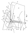
- FIG. 1 Diagrammatically shown in figure 1 a discoverable vehicle 1 having a rigid roof 2 folding inside the trunk 3 of the vehicle.
- the folding hardtop 2 comprises a rear roof portion 4, shown in FIG in its deployed position on the passenger compartment 5 of the vehicle, and mounted pivotally about an axis (not shown) transverse relative to the vehicle.
- the folding hardtop 2 also has a front roof portion 6 diagrammatically dashed in its folded position inside the trunk 3, this front roof portion 6 is generally articulated in its rear region to the front region of the game. rear roof 4.
- the cover 7 of the trunk 3 must open from the front of the rear, in the direction of the arrow 8, while the rear shelf system 9 must be retracted.
- the retractable rear shelf system 9 shown in FIG. figure 1 comprises at least one central tablet 10 and means for moving the tablet central 10 in both directions between its substantially horizontal normal position, shown in solid lines in the figure, and a stored position inside the rear trunk 3, substantially against the wall, schematized in 11 (see figure 2 ), limiting the trunk 3 towards the front of the vehicle, in which one can fold the folding roof 2 inside the trunk 3.
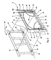
- the central shelf 10 comprises, on each lateral edge 12, a first and a second members forming cam rollers 13, 14, projecting outwards with respect to said lateral edge 12 and adapted to cooperate each with a first or second complementary camming member 15, 16 integral with the bodywork 17 of the vehicle 1.
- the cam follower members 13, 14, and the respective camming members 15, 16, are arranged to guide the central shelf 10 along a predetermined path between these two normal and stored positions, in one direction or in the other. other, under the action of actuating means of said central shelf 10 acting near the front edge 18 of said central shelf 10.
- first cam follower member 13 is located adjacent the front edge 18 of the central shelf 10.
- the front edge 18 of the central shelf 10 does not protrude towards the front of the vehicle, in the direction of the arrow 19, with respect to the first complementary cam member 15, which makes it possible to place said first cam 15 relative to the wall 11 limiting forwardly the trunk 3.
- the first complementary cam member, or first cam adapted to cooperate with the first roller member, or first roller, 13, is substantially rectilinear. This makes it possible to define precisely the profile necessary for the second complementary cam member, or second cam, 16, to obtain the desired predetermined path of the central tablet 10.
- the second complementary member forming cam, or second cam, 16, adapted to cooperate with the second member forming a roller, or second roller, 14, is, in its upper part 16a, bent backwards so as to pivot the central shelf 10 in the direction of arrow 20, at the end of its movement towards its normal position.
- the radius of curvature of this curved upper part can be chosen in any way depending on the specific conditions of a given vehicle: the dimensions of the various parts 4.6 of the foldable rigid roof 2 in the folded position of the roof inside rear trunk 3, position of the rear roof portion 4 in its pivoting in one direction or the other, at the end of the movement of the central shelf, position of the backrest 27, etc ....
- the predetermined trajectory of the central shelf 10 from its stowed position of the figure 2 at its normal position of the figure 1 therefore comprises a first section of substantially rectilinear trajectory and close to the vertical, followed by a second upper section controlling the rotation of the tablet 10 in the direction of the arrow 20 when the second roller 14 arrives in the curved upper part of the second cam 16.
- the lower end 15a of the first cam 15 receiving the first roller 13 is situated at a level lower than that 16a of the second cam 16, and at a distance from the lower end 16a of the second cam 16 corresponding to the distance separating the two rollers 13, 14 of the same side edge 12.
- the two lower ends 15a, 16a are arranged relative to each other so as to give the central shelf 10 the desired stowed position.
- the upper end 15b of the first cam 15 is arranged, with respect to the upper end 16b of the second cam 16, at a distance corresponding to the distance separating the two rollers 13, 14 of the same lateral edge, so as to give the central tablet 10 the normal horizontal position sought.
- the two complementary camming members 15, 16, located on the same side of the bodywork 17 are carried by a respective left armature 21, right 22, integral with the body (also called structure or frame) 17 of the vehicle 1.
- first and second cams 15, 16 are formed on the surfaces facing each other of the armatures 21, 22.
- system 9 can also be fixed in any other way on the bodywork 17 of the vehicle 1.
- the backrest 27, of which only the frame has been shown is pivotally mounted about a pivot axis 28 which is located at the bottom of the backrest 27 and which is integral with the bodywork 17 of the vehicle 1, this pivoting being shown schematically by the arrow 29 in the figure.
- the backrest 27 is mounted on a shaft 30 having axis axis 28 and pivotally mounted by means known per se (not shown) on the frame of the seat or directly on the bodywork 17 of the vehicle 1.
- the backrest 27 could be pivotally mounted, in any known manner, with respect to the seat frame or the bodywork.
- the backrest 27 can be moved by any means connected or not to the folding rigid roof system.
- the backrest 27 can thus be moved by a device of the type described, from page 15, line 15, to page 16, line 8, and represented in FIG. figure 8 , from FR-A-2 601 906 , this device being actuated by a connecting rod connected to a pivoting bow of a retractable hood, the hinged head hoop can be replaced by a pivot arm (not shown) of the folding hard roof 2.
- the wall 11 limiting the rear trunk 3 can be fixed to the backrest frame 27. It can also, as shown schematically in FIG. figure 2 , to be fixed to the frame 25 and to be an integral part of the rear shelf system 9 shown which is itself fixed to the backrest 27 by known means such as screws schematized by the dashed lines 31 and passing through the corresponding orifices 32 of the frame 25 and 33 of the file 27.
- the backrest 27 when the folding roof 2 is in its folded position inside the trunk 3, (only the front roof portion 6 is shown in dashed lines at figure 1 ), the backrest 27 is in its forward position, pivoted forwards, shown at 27a in solid lines at the figure 1 to allow a maximum longitudinal distance inside the rear trunk 3 for storing the various parts of the folding roof 2.
- the backrest 27 when the roof is in its deployed position above the passenger compartment 5 of the vehicle 1, the backrest 27 can be in its rearward pivoted position schematically in dashed in 27b to the figure 1 , which is more comfortable for passengers.
- the actuating means of the central shelf 10 may be any known means, the rollers 13, 14 and the cams 15, 16 being shaped correspondingly.
- actuating means could thus be constituted by at least one jack (not shown) located in the lower part of the rear trunk 3 and acting on the front edge 18 of the central shelf 10 or near said front edge 18, so as to guide directly and without risk of jamming the movement of the central shelf 10 between its two positions.
- the cams 15 and 16 could then be simple grooves or slides formed on the frame 21, 22 corresponding, the rollers 13, 14 being simple fingers slidably trapped inside these slides.
- the actuating means comprise a motor 41 which is integral with the bodywork 17 and which drives in a known manner on each side of the vehicle 1 a respective worm 42 forming part of the corresponding first complementary cam member 15.
- the first cam follower member 13 is pivotally mounted on a nut 43 which is locked in rotation and which moves along the worm 42 and the corresponding cam 15 in one direction or the other when the screw 42 rotates in one direction or the other under the action of the motor 41.
- the motor 4 drives each worm 42 by the intermediate of a shaft 45 driving a bevel gear 46.
- the cam follower 13 is for example a finger, not shown, pivotally received in a bearing 44 carried by the nut 43.
- the actuating means comprise a motor 51 fixed under the central shelf 10.
- Each first cam follower member 13 is a respective pinion 52 pivotally mounted on the corresponding lateral edge 12 of the central shelf 10 so as to be meshed with a rack 53 of the corresponding first complementary cam member 15 for moving the central shelf 10 in one direction or the other when the motor 51 rotates in one direction or the other.
- the central shelf 10 carries two lateral shelves 61, 62, which are movably mounted each near a respective lateral edge 12 of the central shelf 10 so as to be each deployed laterally outwardly when the central shelf 10 is in its normal position substantially horizontal, and to be stored under the lower surface 63 of the central shelf 10 when the latter is in its stowed position or must be moved from its normal position to its stored position or vice versa.
- each side shelf 61 is pivotally mounted about a respective pivot axis 64, 65 substantially perpendicular to the central shelf 10, for example according to the embodiment described in the French patent application. 02 05568 in the name of the plaintiff.
- the present invention can be adapted to all types of folding hardtop, the displacement of the central shelf 10 being synchronized with that of the roof so that the shelf 10 does not interfere with the displacement of the roof 2 or vice versa.
- the foregoing applies regardless of which of the various parts of the folding roof 2 which occupies the most forward position when the roof 2 is folded inside the trunk 3.
- the present invention can also be adapted to all types of seat backs or all types of bodywork.
- Retractable side shelves 61, 62 may also be different from those described above.
- the second cam 16 may comprise, in addition to its upper portion 16b curved rearwardly to control the pivoting of the central shelf 10, a non-rectilinear intermediate portion having a predetermined profile chosen to give the central shelf 10 a predetermined path.
- a drive arm 70 is pivotally mounted on the body 17 along an axis of rotation 80 at a first end, and a slideway 420 is formed in the bodywork 17 at the rear trunk.
- the roof 2 is adapted to be driven from one to the other of its positions by the arm 70 which is pivotally connected, at its second end, to the front end of the rear part of the roof, and to be guided in its movement by the rear end of the rear part of the roof which is mounted sliding way in the slides 420.
- the boot lid 7 is movably mounted between a closed position, an open position from front to rear to allow storage of the roof in this trunk, and from the rear to the front to allow the introduction of luggage .
- the front edge 50 of the cover defines the upper front part of the trunk, in particular at the rear level of the rear deck 10 of the vehicle when the cover 7 is in the closed position.
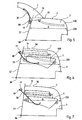
- the vehicle also comprises a device adapted to drive the backrest 27 between a first angular position in which the backrest extends upwards and towards the rear of the vehicle, the roof then being in the extended position ( figure 5 ), and a second angular position in which it extends less towards the rear of the vehicle.
- the first and second angular positions are, respectively, the most rearward and forward angular positions that the backrest can take.
- the backrest 27 is pivotally mounted relative to the bodywork 17 about a pivot axis 90.
- the distance the amplitude of the movement of the upper part of the backrest is important and allows the movement of the roof.
- the device cooperates with the drive arm 70 so as to cause the backrest 27 to pivot as soon as the roof moves, so that the backrest is quickly in front of its first position, making it easier for the roof to move. then, when it is in its second angular position, the distance separating the front edge 50 of the cover 7 in the open position from the front to the rear of the top of the backrest is increased so as to allow the passage of the roof.
- the device comprises transmission means which cooperate with the driving arm 70 and which are adapted to drive the backrest in a back-and-forth movement when the roof passes from one to the other of its positions so that, when the roof 2 is in its folded row position, the backrest 3 is in a third angular position in which it is behind its second angular position.
- the backrest When in this third angular position, the backrest has a sufficient orientation to ensure comfort to the occupant.
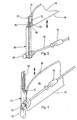
- the transmission means are formed by a connecting rod 130 which is pivotally mounted, on the one hand, by a first end 140, on the drive arm 70, about a first hinge axis 150 extending transversely to the vehicle, and, secondly, by a second end 160, on the backrest 27, about a second hinge axis 170 extending transversely to the vehicle.
- the first end 140 of the rod 130 is pivotally mounted relative to a strip 180 which is integral with the drive arm 70.
- the transmission means are formed by a rod 190 which is integral with the drive arm 70 and whose end free 200 comprises a pin 210 slidably mounted in a groove 220 formed in the folder 27.
- the rotation of the pin 210 about the axis of rotation 80 and its sliding along the groove 220 causes the pivoting of the file around of the pivot axis 90.
- the groove 220 extends mainly radially with respect to the pivot axis 90, along the backrest 27.
- the transmission means drive the backrest in a complete back and forth movement when the roof 2 passes from one to the other of its positions.
- the backrest 27 occupies the same position that the roof is folded up or deployed, and therefore the third angular position corresponds to the first angular position (as illustrated in FIGS. figures 9 and 11 ).
- the storage process illustrated in the figure 9 is as follows: initially, when the roof 2 is deployed, the backrest 27a, c is in its first angular position (solid line), the rod 130a and the strip 180a are in their corresponding position (in solid line); when the folder 27b is in its second angular position (in phantom), the roof is being deployed and the rod 130b and the strip 180b are in their corresponding position (in phantom); when the roof 2 is folded stored, the backrest 27a, c is in its third angular position which is also its first angular position (in solid line), the connecting rod 130c and the strip 180c are in their corresponding position (dashed).
- the one shown in figure 11 is as follows: initially, when the roof is deployed, the backrest 27a, c is in its first angular position (in solid line), the rod 190a (housed in the groove 220a, c) and the arm 70a are in their corresponding position (in solid line); when the back 27b is in its second angular position (in phantom), the roof is being deployed and the rod 190b (housed in the groove 220b) and the arm 70b are in their corresponding position (in phantom); when the roof 2 is folded stored, the backrest 27a, c is in its third angular position which is also its first angular position (in solid line), the rod 190c (housed in the groove 220a, c) and the arm 70c are in their corresponding position (in dotted lines).
- This first conformation has the advantage of providing the person occupying the seat exactly the same comfort, whether the roof is deployed or folded.
- the transmission means cause the backrest 27 in a partial back and forth movement when the roof passes from one to the other of its positions.
- the third angular position is between the first and second angular positions.
- the angular offset between the first and third angular positions is sufficiently small so that the seat remains comfortable when the roof is stored.
- the storage process illustrated in the figure 10 is as follows: initially, when the roof is deployed, the back 27a is in its first angular position (solid line), the rod 130a and the strip 180a are in their corresponding position (in solid line); when the folder 27b is in its second angular position (in phantom), the roof is being deployed and the rod 130b and the strip 180b are in their corresponding position (in phantom); when the roof is folded stored, the backrest 27c is in its third angular position (in dotted line), the connecting rod 130c and the strip 180c are in their corresponding position (in dotted lines).
- the one shown in figure 12 is as follows: initially, when the roof is deployed, the back 27a is in its first angular position (in solid line), the rod 190a and the arm 70a are in their corresponding position (in solid line); when the backrest 27b is in its second angular position (in phantom), the roof is being deployed and the rod 190b and the arm 70b are in their corresponding position (in phantom); when the roof is folded stored, the back 27c is in its third angular position (in dashed lines), the rod 190c and the arm 70c are in their corresponding position (in dashed lines).
- the relative positions of the axis of rotation 80, of the pivot axis 90 and the first and second axes of articulation 150, 170, and the dimension of the connecting rod 130 make it possible to determine the third angular position. of the file 27 ( Figures 9 and 10 ).
- the relative positions of the axis of rotation 80 and the pivot axis 90 and the shape of the groove 220 determine the third angular position of the backrest 27 ( Figures 11 and 12 ).
- the backrest 27 and the bodywork 17 comprise respective immobilizing means which are arranged to allow the immobilization of the backrest when the latter is in its first angular position or in its third angular position. In this way, these immobilization means provide additional rigidity in the transverse direction of the vehicle.
- the backrest 27 comprises, at each of its transverse ends, a finger 240 which is movable in the transverse direction between an outward position of the backrest and a retracted position.
- Actuating means such as a motor (not shown), can be integrated in the backrest in order to drive the fingers 240 both towards their extended position and towards their retracted position.
- the bodywork 17 comprises, on each side, first 250 and second 260 orifices which are adapted to receive the corresponding finger 240 in the extended position when the backrest is respectively in its first and third angular positions.
- the backrest is rigidly fixed to the bodywork 17 whether in its first or third angular position.
- the body comprises, on each side, a single orifice which is adapted to receive the corresponding finger 240 in the extended position when the file 27 is in its first (third ) angular position (whether the roof is stowed or deployed).
- the bodywork 17 comprises, on each side, a slideway 270 (forming guiding means) which is adapted to receive sliding way the corresponding finger 240 in the retracted position when the backrest pivots.
- the slide 270 extends between the orifice 250 receiving the finger 240 in the extended position when the backrest 27 is in its first angular position and an end 410 in front of which is located the finger 240 when the backrest is in its second angular position. .
- the depth of the slide 270 is less than that of the orifices 250, 260.
- the slide 270 forms an arc having the center of the pivot axis 90.
- the backrest In order to increase the amplitude of movement of the upper part of the backrest 27 (the folded roof accommodating in the upper part of the trunk), the backrest is mounted on the bodywork 17 pivotally about the pivot axis 90 by its lower shaft 100 located at the lower end of the backrest 3.
- the pivoting connection of the lower shaft 10 to the bodywork 4 is done by means, on the one hand, of a sliding bearing 110 receiving the central part of the body. lower shaft 100, and, secondly, two bases 120, each base receiving an axial end of the lower shaft 100, the sliding bearing and the two bases being fixed to the bodywork 17.
- the two fingers 240 are arranged in a transverse center bar 400 parallel to the pivot axis 90 located near the upper end of the backrest 27.
- safety hoops 280 are mounted not on the bodywork, but on the backrest (its structure 27 ') and move at the same time as the latter.
- the device according to the present invention has the particular advantage of constituting a module autonomous and complete that can be mounted on a vehicle.
- This module comprises the backrest 27, the transmission means 130,190, the immobilization means 240,250,260, the guide means 270, the plain bearing 110 and the bases 120 for imparting good rigidity to the vehicle, and the roll bars 280.
- the backrest prefferably has at each of its transverse ends an orifice, the bodywork comprising, on each side, first and second fingers movable in a transverse direction between a retracted position and an extended position in which they are adapted to penetrate. in the corresponding hole when the folder is respectively in its first and third angular position.
- the bodywork comprising, on each side, a movable finger.
Landscapes
- Engineering & Computer Science (AREA)
- Mechanical Engineering (AREA)
- Seats For Vehicles (AREA)
- Body Structure For Vehicles (AREA)
- Fittings On The Vehicle Exterior For Carrying Loads, And Devices For Holding Or Mounting Articles (AREA)
- Motorcycle And Bicycle Frame (AREA)
Claims (13)
- Modularer Verbund, umfassend:- eine Einrichtung ausgelegt zum Schwenken einer Rückenstütze (27) eines Sitzes um eine sich im unteren Abschnitt dieser Rückenstütze befindenden Achse (28, 90), welche den Heckkofferraum (3) eines aufdeckbaren Fahrzeugs (1) nach vorne begrenzt, umfassend ein zusammenfaltbares starres Dach (2) angetrieben über einen in schwenkbarer Weise an der Karosserie (17) des Fahrzeugs montierten Antriebsarm (70), zwischen einer entfalteten und einer gefalteten in den Heckkofferraum eingeräumten Position, wobei die Einrichtung dazu ausgelegt ist, wenn das Dach von der einen in die andere seiner Positionen bewegt wird, die Rückenstütze (27) zu schwenken zwischen einer ersten angewinkelten Position in der die Rückenstütze sich in das Hintere des Fahrzeugs erstreckt und in der das Dach (2) in seiner entfalteten Position ist, und einer zweiten angewinkelten Position, in der die Rückenstütze sich weiter vorne befindet, in einer Weise um die Passage des Daches zwischen der Rückenstütze und dem vorderen Rand (50) der Haube (7) zu erlauben, wenn diese in geöffneter Position ist, gekennzeichnet durch,- ein System einer versenkbaren hinteren Fläche (9), umfassend zumindest eine zentrale Platte (10) und Mittel zum Bewegen der zentralen Platte in die zwei Richtungen zwischen ihrer normalen, etwa horizontalen, und einer eingeräumten Position, im Inneren des Heckkofferraums (3) und etwa bei der Wandung (11), welche den Heckkofferraum nach vorne begrenzt, in dem das zusammenfaltbare Dach (2) in dem Innenraum des Heckkofferraums (3) zusammengefaltet werden kann, die zentrale Platte (10) umfassend an jeder ihrer lateralen Seiten (12), ein erstes und ein zweites Führungsüberstände (galets de came) ausbildende Organ (13, 14), welche nach außen über diese lateralen Seiten (12) überstehen und welche jede dazu ausgelegt sind, mit einem ersten oder einem zweiten eine entsprechende Führung (came) ausbildenden Komplementärorgan (15, 16) zu kooperieren, im Zusammenhalt mit der Karosserie (17) des Fahrzeugs, wobei die Führungsüberstände ausbildenden Organe (13, 14) und die entsprechende Führungen ausbildenden Komplementärorgane (15, 16) zum Führen der zentralen Platte (10) in einer Weise zusammengesetzt sind entsprechend einer vorbestimmten Trajektorie zwischen ihren zwei Positionen, normal und eingeräumt, in einer Richtung oder in der anderen, unter Aktivität von Antriebsmitteln der zentralen Platte, agierend in der Nähe der vordere Kante (18) der zentralen Platte, wobei die zwei Führungen ausbildenden Komplementärorgane (15, 16), welche sich auf einer gleichen Seite der Karosserie befinden, jeweils von einem Gestell (21, 22) getragen sind, im Zusammenhalt mit der Karosserie des Fahrzeugs, wobei jedes Gestell (21, 22) dazu ausgelegt ist, an der entsprechenden hinteren Oberfläche der Rückenstütze des Sitzes (27) fixiert zu werden.
- Modularer Verbund nach Anspruch 1, dadurch gekennzeichnet, dass die Gestelle (21, 22) über Stege (23, 24) miteinander verbunden sind, um einen Rahmen (25) zu bilden, tragend die Platte (10) in einer Weise zum Ausbilden eines Systems einer hinteren Fläche (9) mit einem einzigen Halter.
- Modularer Verbund nach Anspruch 1 oder 2, dadurch gekennzeichnet, dass in dem System einer hinteren Fläche (9), das erste eine Führung ausbildende Komplementärorgan (15), dazu ausgelegt mit dem ersten einen Führungsüberstand ausbildenden Organ (13) zu kooperieren, etwa geradlinig ist und das zweite eine Führung ausbildende Komplementärorgan (16), dazu ausgelegt mit dem zweiten einen Führungsüberstand ausbildenden Organ (14) zu kooperieren, in seinem oberen Bereich (16a) nach hinten gekrümmt ist, in einer Weise zum Schwenken der zentralen Platte (10) nach hinten am Ende ihrer Bewegung in ihre normale Position.
- Modularer Verbund nach einem der vorangehenden Ansprüche, dadurch gekennzeichnet, dass in dem System einer hinteren Fläche, die Antriebsmittel einen Motor (51) umfassen, befestigt unter der zentralen Platte (10), wobei jedes einen Führungsüberstand ausbildende Organ (13) ein Triebrad (52) ist, jeweils montiert an der entsprechenden lateralen Seite (12) der zentralen Platte (10), in einer Weise zum Eingreifen in eine entsprechende Zahnstange (53) zum Bewegen der zentralen Platte (10) in eine Richtung oder die andere, wenn der Motor (51) in eine Richtung oder die andere dreht.
- Modularer Verbund nach einem der vorangehenden Ansprüche, dadurch gekennzeichnet, dass in dem System einer hinteren Fläche die zentrale Platte (10) zwei laterale Platten (61, 62) trägt, welche jede beweglich jeweils an einer lateralen Seite (12) der zentralen Platte (10) montiert sind, in einer Weise, so dass jede lateral nach außen aufklappbar ist, wenn die zentrale Platte (10) in ihrer normalen etwa horizontalen Position ist, und so, dass sie eingeräumt sind unter der zentralen Platte (10), wenn diese in ihrer eingeräumten Position ist.
- Aufdeckbares Fahrzeug (1) umfassend,- eine Karosserie (17),- einen Heckkofferraum (3),- ein zusammenfaltbares starres Dach (2), angetrieben über einen Antriebsarm (70) in einer schwenkbaren Weise an der Karosserie (17) montiert, zwischen einer entfalteten und einer gefalte ten Position, eingeräumt in dem Kofferraum,- eine Rückenstütze (27) eines Sitzes schwenkbar montiert um eine sich im unteren Bereich dieser Rückenstütze befindende Achse (28, 90), welche nach vorne den Heckkofferraum begrenzt,- und einen modularen Verbund nach einem der vorangehenden Ansprüche.
- Fahrzeug nach Anspruch 6, dadurch gekennzeichnet, dass die Schwenkeinrichtung für die Rückenstütze des Sitzes (27) Mittel umfasst zur Übertragung (130, 190), welche mit dem Antriebsarm (70) kooperieren, und welche dazu ausgelegt sind, die Rückenstütze (27) mit einer hin-und-her Bewegung so anzutreiben, dass, wenn das Dach (2) in seiner gefalteten eingeräumten Position ist, die Rückenstütze sich in einer dritten angewinkelten Position befindet, in der sie sich hinter ihrer zweiten angewinkelten Position befindet.
- Fahrzeug nach Anspruch 7, dadurch gekennzeichnet, dass die Übertragungsmittel (130) durch ein in schwenkbarer Weise montiertes Pleuel (130) ausgebildet sind, einerseits über ein erstes Endstück (140) an dem Antriebsarm (70), und, andererseits über ein zweites Endstück (160), an der Rückenstütze (27).
- Fahrzeug nach Anspruch 7, dadurch gekennzeichnet, dass die Übertragungsmittel (190) durch einen Stängel (190) ausgebildet sind, im Zusammenhalt mit dem Antriebsarm (70), dessen freies Endstück (200) einen Zapfen (200) umfasst, der in verschiebbarer Weise in einer in der Rückenstütze (27) realisierten Nut (220) montiert ist.
- Fahrzeug nach einem der Ansprüche 6 bis 9, dadurch gekennzeichnet, dass die Rückenstütze (27) und die Karosserie jeweils Mittel zur Immobilisation umfassen, welche in einer Weise agieren, die die Immobilisation der Rückenstütze erlaubt, wenn die letztere in ihren ersten und dritten angewinkelten Positionen ist.
- Fahrzeug nach Anspruch 10, dadurch gekennzeichnet, dass die Rückenstütze (27) aufweist, an jedem ihrer querliegenden Endstücke, einen in Querrichtung zwischen einer ausgefahrenen Position und einer eingefahrenen Position beweglichen Finger (240), die Karosserie (17) umfassend, an jeder Seite, erste (250) und zweite (260) Öffnungen, welche ausgelegt sind zum Aufnehmen des entsprechenden Fingers (240) in der ausgefahrenen Position, wenn die Rückenstütze jeweils in ihren ersten und dritten angewinkelten Positionen ist.
- Fahrzeug nach Anspruch 11, dadurch gekennzeichnet, dass die Karosserie (17) an jeder Seite aufweist, eine Führungsschiene (270), welche ausgelegt ist zur Aufnahme des entsprechenden Fingers (240) in einer eingefahrenen Position in einer schiebenden Weise,
wenn die Rückenstütze schwenkt, und welche sich erstreckt zwischen der ersten Öffnung (250) und einem gegenüberliegenden Ort, in dem der Finger (240) sich befindet, wenn die Rückenstütze (27) in ihrer zweiten angewinkelten Position ist. - Fahrzeug nach einem der Ansprüche 6 bis 12, dadurch gekennzeichnet, dass in dem System einer hinteren Fläche, die Antriebsmittel einen Motor (41) umfassen, welcher mit der Karosserie (17) zusammenhält und welcher an jeder Seite des Fahrzeugs (1) jeweils eine Schnecke (42) antreibt, einen Teil bildend des ersten entsprechenden eine Führung ausbildenden Komplementärorgans (15), und wobei das erste einen Führungsüberstand ausbildende Organ (13) in schwenkbarer Weise mit einer bezüglich ihrer Drehung blockierten Mutter (43) montiert ist, und welches sich entsprechend entlang der Schnecke (42) in eine Richtung oder in die andere Richtung verschiebt, wenn die Schraube (42) in eine Richtung oder in die andere Richtung dreht unter der Aktion des Motors (41).
Applications Claiming Priority (5)
| Application Number | Priority Date | Filing Date | Title |
|---|---|---|---|
| FR0213606A FR2846603B1 (fr) | 2002-10-30 | 2002-10-30 | Systeme de plage arriere escamotable |
| FR0213606 | 2002-10-30 | ||
| FR0304894A FR2853866B1 (fr) | 2003-04-18 | 2003-04-18 | Dispositif adapte a faire pivoter un dossier de siege delimitant le coffre arriere d'un vehicule |
| FR0304894 | 2003-04-18 | ||
| PCT/FR2003/003226 WO2004041573A1 (fr) | 2002-10-30 | 2003-10-29 | Assemblage modulaire pour vehicule avec un toit repliable et vehicule correspondant |
Publications (2)
| Publication Number | Publication Date |
|---|---|
| EP1556239A1 EP1556239A1 (de) | 2005-07-27 |
| EP1556239B1 true EP1556239B1 (de) | 2008-08-20 |
Family
ID=32313948
Family Applications (1)
| Application Number | Title | Priority Date | Filing Date |
|---|---|---|---|
| EP03767858A Expired - Lifetime EP1556239B1 (de) | 2002-10-30 | 2003-10-29 | Modulare montageeinheit für ein kfz mit faltbarem dach und ein kfz mit solch einer einheit |
Country Status (5)
| Country | Link |
|---|---|
| EP (1) | EP1556239B1 (de) |
| AT (1) | ATE405443T1 (de) |
| AU (1) | AU2003292292A1 (de) |
| DE (1) | DE60323118D1 (de) |
| WO (1) | WO2004041573A1 (de) |
Families Citing this family (5)
| Publication number | Priority date | Publication date | Assignee | Title |
|---|---|---|---|---|
| DE102004024227A1 (de) * | 2004-05-15 | 2005-12-01 | Wilhelm Karmann Gmbh | Cabriolet-Fahrzeug |
| FR2898841B1 (fr) * | 2006-03-22 | 2009-03-06 | Peugeot Citroen Automobiles Sa | Vehicule automobile de type berline convertible pick-up. |
| DE102006054397A1 (de) | 2006-11-18 | 2008-05-21 | Wilhelm Karmann Gmbh | Cabriolet-Fahrzeug mit einem unter einem Verdeckkastendeckel ablegbaren Verdeck, Verdeckkastenmodul sowie Verfahren zum Betätigen eines Verdeckdeckels |
| DE102007055055A1 (de) * | 2007-11-16 | 2009-05-20 | Wilhelm Karmann Gmbh | Vorrichtung zum Abdecken eines Öffnungsquerschnittes eines Ablagebereiches einer Verdeckeinrichtung eines Cabriolets |
| DE102008051994B4 (de) | 2008-10-16 | 2020-07-02 | Brose Fahrzeugteile SE & Co. Kommanditgesellschaft, Coburg | Verstellvorrichtung sowie Verfahren zum Verstellen einer Abdeckung eines Verdeck-Stauraums eines Cabriolets |
Family Cites Families (8)
| Publication number | Priority date | Publication date | Assignee | Title |
|---|---|---|---|---|
| US2762648A (en) * | 1953-06-16 | 1956-09-11 | Chrysler Corp | Interconnected vehicle rear window and seat for movement in unison |
| FR2601906B1 (fr) * | 1986-07-24 | 1989-07-21 | Heuliez Henri France Design | Capote escamotable a arceaux de securite, pour cabriolets automobiles. |
| DE4232147C1 (de) * | 1992-09-25 | 1993-09-16 | Bayerische Motoren Werke Ag | Abdeckung für eine Durchtrittsöffnung an einem Kraftfahrzeug mit Faltverdeck |
| DE19820338B4 (de) * | 1998-05-07 | 2005-07-28 | Daimlerchrysler Ag | Kraftfahrzeug |
| DE29812164U1 (de) * | 1998-07-08 | 1999-05-06 | Wilhelm Karmann GmbH, 49084 Osnabrück | Cabriolet-Fahrzeug mit einem Verdeckkasten |
| DE29812165U1 (de) * | 1998-07-08 | 1999-05-06 | Wilhelm Karmann GmbH, 49084 Osnabrück | Cabriolet-Fahrzeug mit einem Verdeckkasten |
| FR2802477B1 (fr) * | 1999-12-20 | 2002-03-01 | France Design | Obturateurs lateraux et plage arriere basculants pour passage d'un toit escamotable |
| DE10060404A1 (de) * | 2000-12-05 | 2002-06-06 | Bayerische Motoren Werke Ag | Fahrzeug mit Klappverdeck |
-
2003
- 2003-10-29 DE DE60323118T patent/DE60323118D1/de not_active Expired - Fee Related
- 2003-10-29 EP EP03767858A patent/EP1556239B1/de not_active Expired - Lifetime
- 2003-10-29 WO PCT/FR2003/003226 patent/WO2004041573A1/fr not_active Ceased
- 2003-10-29 AU AU2003292292A patent/AU2003292292A1/en not_active Abandoned
- 2003-10-29 AT AT03767858T patent/ATE405443T1/de not_active IP Right Cessation
Also Published As
| Publication number | Publication date |
|---|---|
| DE60323118D1 (de) | 2008-10-02 |
| ATE405443T1 (de) | 2008-09-15 |
| AU2003292292A1 (en) | 2004-06-07 |
| WO2004041573A1 (fr) | 2004-05-21 |
| EP1556239A1 (de) | 2005-07-27 |
Similar Documents
| Publication | Publication Date | Title |
|---|---|---|
| EP1525109A1 (de) | System einer hutablage für fahrzeug mit einem klappbaren festem dach | |
| EP1282536B1 (de) | Versenkbares starres dachsystem für cabriofahrzeug | |
| EP1706284B1 (de) | Schliessvorrichtung für ein mit einer luke und einem sonnendach versehenes fahrzeug | |
| EP1613495B1 (de) | Ablagesystem für ein cabriofahrzeug mit faltverdeck | |
| EP1255014A1 (de) | Schiebetüranordnung für ein Kraftfahrzeug | |
| EP1556239B1 (de) | Modulare montageeinheit für ein kfz mit faltbarem dach und ein kfz mit solch einer einheit | |
| WO2005007435A2 (fr) | Véhicule à toit ouvrant escamotable et procédé de rangement d'un tel toit, avec basculement horizontal. | |
| EP1633585B1 (de) | Fahrzeug mit einem vertikal klappbaren sonnendach | |
| WO2003093043A1 (fr) | Systeme de plage arriere escamotable pour vehicule decouvrable a toit repliable | |
| EP2093106A1 (de) | Hintere Ablage eines Kraftfahrzeugs, das mit einem Stauraum ausgestattet ist, und entsprechendes Fahrzeug | |
| EP1808330A2 (de) | Sitz für Kraftfahrzeug, der entlang einer ersten Achse x und einer zweiten Achse y beweglich ist, und Kraftfahrzeug, das einen solchen Sitz umfasst | |
| EP1637390B1 (de) | Modulares Fahrzeug und zugehöriges Verfahren | |
| FR2857626A1 (fr) | Vehicule a module de toit ouvrant integre | |
| FR2824356A1 (fr) | Agencement d'une porte coulissante de vehicule automobile | |
| EP1706283A1 (de) | Ein sonnendach und eine luke umfassendes fahrzeug | |
| FR2846603A1 (fr) | Systeme de plage arriere escamotable | |
| FR2854353A1 (fr) | Element arriere de toit escamotable et vehicule ainsi equipe | |
| FR2890006A1 (fr) | Vehicule automobile a toit escamotable. | |
| WO2005082655A1 (fr) | Vehicule a toit ouvrant repliable verticalement | |
| FR2880844A1 (fr) | Vehicule automobile transformable en vehicule decouvert type cabriolet | |
| WO2005012017A2 (fr) | Element arriere de toit escamotable et vehicule ainsi equipe | |
| FR2853866A1 (fr) | Dispositif adapte a faire pivoter un dossier de siege delimitant le coffre arriere d'un vehicule | |
| EP1719654A1 (de) | Cabriolet-Fahrzeug vom Typ Coupé mit Festdach und C-Säulen | |
| FR2979372A1 (fr) | Charniere pour volet de coffre et lunette arriere oscillante de vehicule, toit retractable sous la lunette arriere. | |
| FR2760699A1 (fr) | Vehicule automobile a siege fixe et tablette arriere |
Legal Events
| Date | Code | Title | Description |
|---|---|---|---|
| PUAI | Public reference made under article 153(3) epc to a published international application that has entered the european phase |
Free format text: ORIGINAL CODE: 0009012 |
|
| 17P | Request for examination filed |
Effective date: 20050218 |
|
| AK | Designated contracting states |
Kind code of ref document: A1 Designated state(s): AT BE BG CH CY CZ DE DK EE ES FI FR GB GR HU IE IT LI LU MC NL PT RO SE SI SK TR |
|
| AX | Request for extension of the european patent |
Extension state: AL LT LV MK |
|
| 111L | Licence recorded |
Free format text: 0100 FRANCE DESIGN Effective date: 20051005 |
|
| DAX | Request for extension of the european patent (deleted) | ||
| GRAP | Despatch of communication of intention to grant a patent |
Free format text: ORIGINAL CODE: EPIDOSNIGR1 |
|
| GRAS | Grant fee paid |
Free format text: ORIGINAL CODE: EPIDOSNIGR3 |
|
| GRAA | (expected) grant |
Free format text: ORIGINAL CODE: 0009210 |
|
| AK | Designated contracting states |
Kind code of ref document: B1 Designated state(s): AT BE BG CH CY CZ DE DK EE ES FI FR GB GR HU IE IT LI LU MC NL PT RO SE SI SK TR |
|
| REG | Reference to a national code |
Ref country code: GB Ref legal event code: FG4D Free format text: NOT ENGLISH |
|
| REG | Reference to a national code |
Ref country code: CH Ref legal event code: EP Ref country code: CH Ref legal event code: PK Free format text: COMPLETEMENT D'ENREGISTREMENT DE LICENCE: LICENCE NON-EXCLUSIVE |
|
| REG | Reference to a national code |
Ref country code: IE Ref legal event code: FG4D Free format text: LANGUAGE OF EP DOCUMENT: FRENCH |
|
| REF | Corresponds to: |
Ref document number: 60323118 Country of ref document: DE Date of ref document: 20081002 Kind code of ref document: P |
|
| PG25 | Lapsed in a contracting state [announced via postgrant information from national office to epo] |
Ref country code: NL Free format text: LAPSE BECAUSE OF FAILURE TO SUBMIT A TRANSLATION OF THE DESCRIPTION OR TO PAY THE FEE WITHIN THE PRESCRIBED TIME-LIMIT Effective date: 20080820 Ref country code: ES Free format text: LAPSE BECAUSE OF FAILURE TO SUBMIT A TRANSLATION OF THE DESCRIPTION OR TO PAY THE FEE WITHIN THE PRESCRIBED TIME-LIMIT Effective date: 20081201 |
|
| PGFP | Annual fee paid to national office [announced via postgrant information from national office to epo] |
Ref country code: DE Payment date: 20081027 Year of fee payment: 6 |
|
| PG25 | Lapsed in a contracting state [announced via postgrant information from national office to epo] |
Ref country code: AT Free format text: LAPSE BECAUSE OF FAILURE TO SUBMIT A TRANSLATION OF THE DESCRIPTION OR TO PAY THE FEE WITHIN THE PRESCRIBED TIME-LIMIT Effective date: 20080820 Ref country code: SI Free format text: LAPSE BECAUSE OF FAILURE TO SUBMIT A TRANSLATION OF THE DESCRIPTION OR TO PAY THE FEE WITHIN THE PRESCRIBED TIME-LIMIT Effective date: 20080820 Ref country code: FI Free format text: LAPSE BECAUSE OF FAILURE TO SUBMIT A TRANSLATION OF THE DESCRIPTION OR TO PAY THE FEE WITHIN THE PRESCRIBED TIME-LIMIT Effective date: 20080820 |
|
| REG | Reference to a national code |
Ref country code: IE Ref legal event code: FD4D |
|
| BERE | Be: lapsed |
Owner name: SOC. EUROPEENNE DE BREVETS AUTOMOBILES Effective date: 20081031 |
|
| PG25 | Lapsed in a contracting state [announced via postgrant information from national office to epo] |
Ref country code: DK Free format text: LAPSE BECAUSE OF FAILURE TO SUBMIT A TRANSLATION OF THE DESCRIPTION OR TO PAY THE FEE WITHIN THE PRESCRIBED TIME-LIMIT Effective date: 20080820 Ref country code: IE Free format text: LAPSE BECAUSE OF FAILURE TO SUBMIT A TRANSLATION OF THE DESCRIPTION OR TO PAY THE FEE WITHIN THE PRESCRIBED TIME-LIMIT Effective date: 20080820 Ref country code: BG Free format text: LAPSE BECAUSE OF FAILURE TO SUBMIT A TRANSLATION OF THE DESCRIPTION OR TO PAY THE FEE WITHIN THE PRESCRIBED TIME-LIMIT Effective date: 20081120 |
|
| PG25 | Lapsed in a contracting state [announced via postgrant information from national office to epo] |
Ref country code: CZ Free format text: LAPSE BECAUSE OF FAILURE TO SUBMIT A TRANSLATION OF THE DESCRIPTION OR TO PAY THE FEE WITHIN THE PRESCRIBED TIME-LIMIT Effective date: 20080820 Ref country code: RO Free format text: LAPSE BECAUSE OF FAILURE TO SUBMIT A TRANSLATION OF THE DESCRIPTION OR TO PAY THE FEE WITHIN THE PRESCRIBED TIME-LIMIT Effective date: 20080820 Ref country code: MC Free format text: LAPSE BECAUSE OF NON-PAYMENT OF DUE FEES Effective date: 20081031 Ref country code: SK Free format text: LAPSE BECAUSE OF FAILURE TO SUBMIT A TRANSLATION OF THE DESCRIPTION OR TO PAY THE FEE WITHIN THE PRESCRIBED TIME-LIMIT Effective date: 20080820 Ref country code: PT Free format text: LAPSE BECAUSE OF FAILURE TO SUBMIT A TRANSLATION OF THE DESCRIPTION OR TO PAY THE FEE WITHIN THE PRESCRIBED TIME-LIMIT Effective date: 20090120 |
|
| REG | Reference to a national code |
Ref country code: CH Ref legal event code: PL |
|
| PLBE | No opposition filed within time limit |
Free format text: ORIGINAL CODE: 0009261 |
|
| STAA | Information on the status of an ep patent application or granted ep patent |
Free format text: STATUS: NO OPPOSITION FILED WITHIN TIME LIMIT |
|
| 26N | No opposition filed |
Effective date: 20090525 |
|
| GBPC | Gb: european patent ceased through non-payment of renewal fee |
Effective date: 20081120 |
|
| PG25 | Lapsed in a contracting state [announced via postgrant information from national office to epo] |
Ref country code: EE Free format text: LAPSE BECAUSE OF FAILURE TO SUBMIT A TRANSLATION OF THE DESCRIPTION OR TO PAY THE FEE WITHIN THE PRESCRIBED TIME-LIMIT Effective date: 20080820 |
|
| PG25 | Lapsed in a contracting state [announced via postgrant information from national office to epo] |
Ref country code: IT Free format text: LAPSE BECAUSE OF FAILURE TO SUBMIT A TRANSLATION OF THE DESCRIPTION OR TO PAY THE FEE WITHIN THE PRESCRIBED TIME-LIMIT Effective date: 20080820 |
|
| PG25 | Lapsed in a contracting state [announced via postgrant information from national office to epo] |
Ref country code: BE Free format text: LAPSE BECAUSE OF NON-PAYMENT OF DUE FEES Effective date: 20081031 |
|
| PG25 | Lapsed in a contracting state [announced via postgrant information from national office to epo] |
Ref country code: LI Free format text: LAPSE BECAUSE OF NON-PAYMENT OF DUE FEES Effective date: 20081031 Ref country code: CH Free format text: LAPSE BECAUSE OF NON-PAYMENT OF DUE FEES Effective date: 20081031 |
|
| PG25 | Lapsed in a contracting state [announced via postgrant information from national office to epo] |
Ref country code: GB Free format text: LAPSE BECAUSE OF NON-PAYMENT OF DUE FEES Effective date: 20081120 |
|
| PG25 | Lapsed in a contracting state [announced via postgrant information from national office to epo] |
Ref country code: SE Free format text: LAPSE BECAUSE OF FAILURE TO SUBMIT A TRANSLATION OF THE DESCRIPTION OR TO PAY THE FEE WITHIN THE PRESCRIBED TIME-LIMIT Effective date: 20081120 |
|
| PG25 | Lapsed in a contracting state [announced via postgrant information from national office to epo] |
Ref country code: CY Free format text: LAPSE BECAUSE OF FAILURE TO SUBMIT A TRANSLATION OF THE DESCRIPTION OR TO PAY THE FEE WITHIN THE PRESCRIBED TIME-LIMIT Effective date: 20080820 Ref country code: LU Free format text: LAPSE BECAUSE OF NON-PAYMENT OF DUE FEES Effective date: 20081029 Ref country code: HU Free format text: LAPSE BECAUSE OF FAILURE TO SUBMIT A TRANSLATION OF THE DESCRIPTION OR TO PAY THE FEE WITHIN THE PRESCRIBED TIME-LIMIT Effective date: 20090221 Ref country code: DE Free format text: LAPSE BECAUSE OF NON-PAYMENT OF DUE FEES Effective date: 20100501 |
|
| PG25 | Lapsed in a contracting state [announced via postgrant information from national office to epo] |
Ref country code: TR Free format text: LAPSE BECAUSE OF FAILURE TO SUBMIT A TRANSLATION OF THE DESCRIPTION OR TO PAY THE FEE WITHIN THE PRESCRIBED TIME-LIMIT Effective date: 20080820 |
|
| PG25 | Lapsed in a contracting state [announced via postgrant information from national office to epo] |
Ref country code: GR Free format text: LAPSE BECAUSE OF FAILURE TO SUBMIT A TRANSLATION OF THE DESCRIPTION OR TO PAY THE FEE WITHIN THE PRESCRIBED TIME-LIMIT Effective date: 20081121 |
|
| PGFP | Annual fee paid to national office [announced via postgrant information from national office to epo] |
Ref country code: FR Payment date: 20131030 Year of fee payment: 11 |
|
| REG | Reference to a national code |
Ref country code: FR Ref legal event code: ST Effective date: 20150630 |
|
| PG25 | Lapsed in a contracting state [announced via postgrant information from national office to epo] |
Ref country code: FR Free format text: LAPSE BECAUSE OF NON-PAYMENT OF DUE FEES Effective date: 20141031 |