EP1599330B1 - Procede et dispositif pour fabriquer des corps creux - Google Patents
Procede et dispositif pour fabriquer des corps creux Download PDFInfo
- Publication number
- EP1599330B1 EP1599330B1 EP04706117A EP04706117A EP1599330B1 EP 1599330 B1 EP1599330 B1 EP 1599330B1 EP 04706117 A EP04706117 A EP 04706117A EP 04706117 A EP04706117 A EP 04706117A EP 1599330 B1 EP1599330 B1 EP 1599330B1
- Authority
- EP
- European Patent Office
- Prior art keywords
- blow molding
- plastic tube
- extruder head
- blowing
- molding tool
- Prior art date
- Legal status (The legal status is an assumption and is not a legal conclusion. Google has not performed a legal analysis and makes no representation as to the accuracy of the status listed.)
- Expired - Lifetime
Links
- 238000000034 method Methods 0.000 title claims abstract description 64
- 238000004519 manufacturing process Methods 0.000 title claims abstract description 22
- 239000004033 plastic Substances 0.000 claims abstract description 105
- 229920003023 plastic Polymers 0.000 claims abstract description 105
- 238000001125 extrusion Methods 0.000 claims abstract description 90
- 238000000071 blow moulding Methods 0.000 claims description 113
- 238000007664 blowing Methods 0.000 claims description 78
- 230000033001 locomotion Effects 0.000 claims description 34
- 239000003000 extruded plastic Substances 0.000 claims description 9
- 238000000926 separation method Methods 0.000 claims description 7
- 238000012546 transfer Methods 0.000 claims description 3
- 238000010101 extrusion blow moulding Methods 0.000 description 16
- 239000000463 material Substances 0.000 description 6
- -1 drinks Substances 0.000 description 4
- 238000010923 batch production Methods 0.000 description 3
- 238000013461 design Methods 0.000 description 3
- 238000006073 displacement reaction Methods 0.000 description 3
- 230000010355 oscillation Effects 0.000 description 3
- 239000002699 waste material Substances 0.000 description 3
- 229920000426 Microplastic Polymers 0.000 description 2
- 238000010276 construction Methods 0.000 description 2
- 238000001816 cooling Methods 0.000 description 2
- 238000005520 cutting process Methods 0.000 description 2
- 238000002347 injection Methods 0.000 description 2
- 239000007924 injection Substances 0.000 description 2
- 238000000465 moulding Methods 0.000 description 2
- 238000012805 post-processing Methods 0.000 description 2
- 238000012545 processing Methods 0.000 description 2
- 230000001360 synchronised effect Effects 0.000 description 2
- 239000004698 Polyethylene Substances 0.000 description 1
- 239000004743 Polypropylene Substances 0.000 description 1
- 238000009825 accumulation Methods 0.000 description 1
- 239000000919 ceramic Substances 0.000 description 1
- 238000004140 cleaning Methods 0.000 description 1
- 239000002537 cosmetic Substances 0.000 description 1
- 230000007423 decrease Effects 0.000 description 1
- 230000001419 dependent effect Effects 0.000 description 1
- 238000011161 development Methods 0.000 description 1
- 230000018109 developmental process Effects 0.000 description 1
- 238000010586 diagram Methods 0.000 description 1
- 230000000694 effects Effects 0.000 description 1
- 238000002474 experimental method Methods 0.000 description 1
- 230000002349 favourable effect Effects 0.000 description 1
- 239000012530 fluid Substances 0.000 description 1
- 239000011521 glass Substances 0.000 description 1
- 230000005484 gravity Effects 0.000 description 1
- 230000004886 head movement Effects 0.000 description 1
- 230000014759 maintenance of location Effects 0.000 description 1
- 238000004806 packaging method and process Methods 0.000 description 1
- 239000013502 plastic waste Substances 0.000 description 1
- 229920000573 polyethylene Polymers 0.000 description 1
- 229920001155 polypropylene Polymers 0.000 description 1
- 238000004886 process control Methods 0.000 description 1
- 238000007665 sagging Methods 0.000 description 1
- 238000010008 shearing Methods 0.000 description 1
- 239000000243 solution Substances 0.000 description 1
- 230000000087 stabilizing effect Effects 0.000 description 1
- 239000000126 substance Substances 0.000 description 1
- 238000006467 substitution reaction Methods 0.000 description 1
- 230000008961 swelling Effects 0.000 description 1
Images


Classifications
-
- B—PERFORMING OPERATIONS; TRANSPORTING
- B29—WORKING OF PLASTICS; WORKING OF SUBSTANCES IN A PLASTIC STATE IN GENERAL
- B29C—SHAPING OR JOINING OF PLASTICS; SHAPING OF MATERIAL IN A PLASTIC STATE, NOT OTHERWISE PROVIDED FOR; AFTER-TREATMENT OF THE SHAPED PRODUCTS, e.g. REPAIRING
- B29C49/00—Blow-moulding, i.e. blowing a preform or parison to a desired shape within a mould; Apparatus therefor
- B29C49/02—Combined blow-moulding and manufacture of the preform or the parison
- B29C49/04—Extrusion blow-moulding
-
- B—PERFORMING OPERATIONS; TRANSPORTING
- B29—WORKING OF PLASTICS; WORKING OF SUBSTANCES IN A PLASTIC STATE IN GENERAL
- B29C—SHAPING OR JOINING OF PLASTICS; SHAPING OF MATERIAL IN A PLASTIC STATE, NOT OTHERWISE PROVIDED FOR; AFTER-TREATMENT OF THE SHAPED PRODUCTS, e.g. REPAIRING
- B29C2793/00—Shaping techniques involving a cutting or machining operation
- B29C2793/009—Shaping techniques involving a cutting or machining operation after shaping
-
- B—PERFORMING OPERATIONS; TRANSPORTING
- B29—WORKING OF PLASTICS; WORKING OF SUBSTANCES IN A PLASTIC STATE IN GENERAL
- B29C—SHAPING OR JOINING OF PLASTICS; SHAPING OF MATERIAL IN A PLASTIC STATE, NOT OTHERWISE PROVIDED FOR; AFTER-TREATMENT OF THE SHAPED PRODUCTS, e.g. REPAIRING
- B29C49/00—Blow-moulding, i.e. blowing a preform or parison to a desired shape within a mould; Apparatus therefor
- B29C49/22—Blow-moulding, i.e. blowing a preform or parison to a desired shape within a mould; Apparatus therefor using multilayered preforms or parisons
-
- B—PERFORMING OPERATIONS; TRANSPORTING
- B29—WORKING OF PLASTICS; WORKING OF SUBSTANCES IN A PLASTIC STATE IN GENERAL
- B29C—SHAPING OR JOINING OF PLASTICS; SHAPING OF MATERIAL IN A PLASTIC STATE, NOT OTHERWISE PROVIDED FOR; AFTER-TREATMENT OF THE SHAPED PRODUCTS, e.g. REPAIRING
- B29C49/00—Blow-moulding, i.e. blowing a preform or parison to a desired shape within a mould; Apparatus therefor
- B29C49/28—Blow-moulding apparatus
-
- B—PERFORMING OPERATIONS; TRANSPORTING
- B29—WORKING OF PLASTICS; WORKING OF SUBSTANCES IN A PLASTIC STATE IN GENERAL
- B29C—SHAPING OR JOINING OF PLASTICS; SHAPING OF MATERIAL IN A PLASTIC STATE, NOT OTHERWISE PROVIDED FOR; AFTER-TREATMENT OF THE SHAPED PRODUCTS, e.g. REPAIRING
- B29C49/00—Blow-moulding, i.e. blowing a preform or parison to a desired shape within a mould; Apparatus therefor
- B29C49/42—Component parts, details or accessories; Auxiliary operations
- B29C49/48—Moulds
-
- B—PERFORMING OPERATIONS; TRANSPORTING
- B29—WORKING OF PLASTICS; WORKING OF SUBSTANCES IN A PLASTIC STATE IN GENERAL
- B29C—SHAPING OR JOINING OF PLASTICS; SHAPING OF MATERIAL IN A PLASTIC STATE, NOT OTHERWISE PROVIDED FOR; AFTER-TREATMENT OF THE SHAPED PRODUCTS, e.g. REPAIRING
- B29C49/00—Blow-moulding, i.e. blowing a preform or parison to a desired shape within a mould; Apparatus therefor
- B29C49/42—Component parts, details or accessories; Auxiliary operations
- B29C49/76—Neck calibration
-
- B—PERFORMING OPERATIONS; TRANSPORTING
- B29—WORKING OF PLASTICS; WORKING OF SUBSTANCES IN A PLASTIC STATE IN GENERAL
- B29K—INDEXING SCHEME ASSOCIATED WITH SUBCLASSES B29B, B29C OR B29D, RELATING TO MOULDING MATERIALS OR TO MATERIALS FOR MOULDS, REINFORCEMENTS, FILLERS OR PREFORMED PARTS, e.g. INSERTS
- B29K2023/00—Use of polyalkenes or derivatives thereof as moulding material
- B29K2023/10—Polymers of propylene
- B29K2023/12—PP, i.e. polypropylene
Definitions
- the invention relates to a method for the production of hollow bodies according to the preamble of claim 1.
- the invention also relates to a device suitable for this purpose.
- plastic containers made of white or stained, glass or ceramic are increasingly being replaced by plastic containers.
- plastic containers are used for the packaging of fluid substances, such as drinks, oil, cleaning utensils, cosmetics, etc.
- the low weight and the lower costs certainly play a significant role in this substitution.
- the use of recyclable plastic materials and the overall more favorable overall energy balance in their production also contribute to the consumer's acceptance of plastic containers, in particular of plastic bottles.
- plastic containers in particular plastic bottles, for example made of polyethylene or polypropylene
- extrusion blow molding machines used for this purpose generally have at least one extruder for feeding the plastic material.
- the outlet of the extruder is connected to the extruder head, at the preferably in the opening width of the adjustable outlet nozzle, the one or more extruded extruded tube emerges.
- the extruded tube is transferred to a blow mold and inflated within the cavity with a blow pin.
- the plastic tube can be single-layered or multi-layered, it can be extruded as a tube with viewing strips, decorative strips or related to the circumference with several, for example, different colored segments.
- the blowing station with the mandrel is usually arranged laterally of the extrusion head, and the blow molding tool fed with the extruded tube must be moved into the blowing station, where then the mandrel is usually retracted from above into the Blasformkavtician.
- two blowing stations are usually provided in one type of known extrusion blow molding machines. Each blowing station is equipped with a blow molding tool.
- the blowing stations are arranged on both sides of the extruder, opposite each other and have blow molding with the blow molding tools, which are moved alternately under the extruder head to receive the extruded tube.
- the blow mold is opened to pick up the hose. After closing the blow molding tool, the tube between the extrusion head and the blow mold is separated.
- each blowing station is equipped with a corresponding number of blowing mandrels, which are inserted together into the blow molding cavities.
- the extruder with the extruder head and the two blowing stations form approximately the shape of a T.
- the extruder with the extruder head represents the long T-bar, while the two blow-molding tables are alternately movable along the short cross-half halves under the extruder head.
- Extrusion blow molding machines are also known, in which a number of blow molding tools are arranged on a rotating wheel.
- the wheel is approximately vertical and leads the blow molding approximately tangentially to the extruded from the extrusion head plastic hose.
- the introduced blow mold is opened to pick up the hose.
- the blow mold is closed around the inserted hose and this is finally sheared off as it rotates further.
- the arrangement of the blow molding tools and the rotational speed of the wheel are selected such that the hose is sheared off only when the subsequent blow molding tool has closed around the next piece of hose.
- the tube located in the cavity of the blow molding tool finally passes into the blowing station during further rotation of the wheel, where it is inflated via a blowing mandrel inserted laterally into the molding tool according to the blow molding cavity. Finally, the inflated hollow body is discharged by opening from the blow molding tool.
- the blow molding tool arranged on the rotating wheel is closed again during the further movement and brought back to the extrusion head in order to receive a further extruded hose.
- a disadvantage of the wheel blow molding machines is the fact that they require a relatively high capital outlay for the provision of the blow molding tools because of the large number of arranged on the wheel separate blow molds.
- the blow molds are not completely identical in the rule. This can lead from blow mold to blow mold to quality differences in the produced hollow bodies.
- the use of blow molds with multiple blow mold cavities is relatively difficult and expensive.
- the blow molds are only attachable to firmly fixed mounting points on the wheel. These are determined by the maximum height of the blown hollow body that can be produced by the machine. Once fixed mounting points are no longer changeable. This is also a consequence of the mechanical controls on control cams, cams and the like customary in these machines.
- an apparatus and method for making preforms of non-uniform wall thickness.
- Plastic is pressed into a neck shape to pour a neck of the vessel.
- the opening width of the extrusion head is widened and narrowed, thereby extruding a tubular plastic structure held in a collar shape and having different wall thicknesses between the collar shape and the extrusion head.
- the tubular plastic structure is inflated in a blow mold and separated directly on the extruder head.
- a method of continuously producing plastic containers and an apparatus suitable for such a method are known.
- the plastic tube is introduced from an extruder head into a cavity. With two pressed parts of the plastic tube is pressed together and closed and a bottom formed.
- an injection opening is provided, through which the plastic tube is inflated in the cavity.
- the container is then pulled out of the cavity during the blowing.
- the pressed parts are released from the plastic container and reintroduced into the cavity, in which a new piece of tubing is now present.
- the freshly blown container is grasped by a holder and pulled while the bottom piece is moved back into the cavity. Now the bottom piece presses the plastic tube together again and the inflation of the new bottle begins.
- the tube is further extruded and the pressed parts moved longitudinally in the cavity. The tube is therefore blown during extrusion and displaced within the cavity.
- the object of the present invention is therefore to avoid the disadvantages of the methods and devices of the prior art.
- a blow-molding process and an extrusion blow-molding machine are to be created which permit reliable processing of various plastic raw products.
- the design of the container geometries should be as many open spaces, and it should also be able to produce containers with very complex geometry with very tight specifications.
- the method and the device for extrusion blow molding of hollow bodies should be compatible for the production of large and small geometries. In doing so, unnecessary plastic waste should be largely avoided.
- the method and the device should be modified to the effect that, regardless of the number of cavities per blow mold largely identical container properties and quality parameters can be achieved.
- the adjustment data determined in the experiment should be largely transferable to production plants without any changes.
- the space requirement compared to existing machines should not be greater, yes it should even be possible to reduce this. Dead times, as they occur in the known machines in the lateral displacement of the blow molds in the blow molding stations, should be reduced.
- a section of a plastic tube is introduced into a cavity of a blow molding tool by an extruder head in a predeterminable cycle.
- the plastic tube is inflated via a mandrel by overpressure according to the Blasformkavtician.
- the finished blown hollow body is finally removed from the mold.
- the plastic tubing is continuously held on opposite sides of the blow molder assembly throughout an entire extrusion and blowing cycle.
- the plastic tube is continuous on opposite sides of the blow molding tool assembly during an entire production cycle, ie during an entire extrusion and blowing cycle held.
- the plastic tube is permanently guided and misplaced situations can be avoided.
- the condition is created to always introduce a extruded from an extrusion die hose in the same Blasformkavtician. All of the hollow bodies produced with an extrusion die-blow mold cavity arrangement thus experience the same setting and tool parameters. Differences in quality due to different sized tolerances of Blasformkavticianen omitted in arrangements with several different blow molds.
- Dead times which take place by a lateral displacement of the blow molding tool arrangement with respect to the extruder head, are dispensed with, since the blow mold arrangement is oriented substantially only in the transport direction of the plastic tube.
- the inflating of the plastic hose located in the blow mold cavity takes place immediately after the charging of the blow mold cavity with the extruded plastic hose.
- the plastic tube is held in a defined position during the entire extrusion and Blaszyklusses and can no longer oscillate about its axis.
- the extruder head and the blow molding tool remain in a predeterminable and adjustable, geometric positional relationship throughout the extrusion and blowing process, and the plastic tube can always be optimally adopted.
- the method according to the invention allows the position of the extruded plastic tube with respect to the blow mold cavity to be changed as required in order to take into account special geometrical requirements.
- the plastic tube is separated only after complete inflation of the hollow body.
- the separation can be done by controlled squeezing or by shearing.
- a separating knife or the like is used for this purpose.
- This variant of the method differs both from the blow molding process with the known wheel blow molding machines, in which the tube is sheared after uncontrolled after taking over the blow mold on further rotation of the wheel, as well as the continuous and discontinuous blow molding with known extrusion blow molding machines, in which Plastic hose in front of the actual blow process is controlled cut.
- the method according to the invention requires that the mandrel be synchronized for a certain time with the movement of the extruder head and / or the extrusion or transfer speed of the plastic tube to the blow molding tool arrangement.
- this simple measure ensures that the hose is kept controlled at every stage of the production cycle.
- the separation of the plastic tube is advantageously carried out on the side facing away from the extruder head of Blasformwerkmaschinemaschine fürssenssen. As a result, before the separation of the leadership of the hose on the blow spool located on the finished blown hollow body and the extruder head ensured.
- the separation point By arranging the separation point in the immediate vicinity of the mouth of Blasformkavtician the hose material waste can always be kept as small as possible regardless of the height of Blasformkavtician.
- the Blasformwerkmaschinemaschinenraum is disposed between the extruder head and the mandrel.
- the mandrel is retracted through an opening of the Blasformkavmaschine, which is arranged on the side facing away from the extrusion nozzle side of the Blasformwerkmaschinegnean ever.
- the outlet of the extrusion nozzle and the axial extension of the blowing mandrel are arranged such that they are aligned substantially axially.
- blowing mandrels are provided for reducing the dead times for each blow mold cavity.
- the blowing mandrels can for example be arranged side by side and be delivered alternately to the openings of the blow mold cavities.
- a plurality of blowing mandrels are attached to a central Blasdornhalterung such that they are used by rotation of the Blasdornhalterung successively used.
- the Blasdornhalterung can carry two mandrels, offset by 180 ° to each other.
- the blow mandrel holder is rotated by 180 ° after inflation of the tube and the opening of the blow mold assembly.
- the second mandrel is thus already ready for the inflation of another hose section, while the hollow body is still waiting for its removal at the first mandrel.
- rotatable Blasdornhalterept with 3, 4 or more Blasdornen can be provided.
- the angle by which the Blasdornhalterung must be further rotated, then results from the division of 360 ° by the number Blasdome.
- the arrangement on the side of the blow molding tool arrangement facing away from the extrusion nozzle also offers the possibility of providing each blowing mandrel with a calibrating device with which the opening of the blown hollow body is already calibrated during the blowing process. This eliminates a separate post-processing station, in which this process must be made up.
- the plastic tube is extruded continuously from the extrusion die of the extruder head.
- the relative distance of the extruder head from the blow molder assembly is increased to prevent it from starting against the surface of the blow molder assembly during further extrusion and to maintain the tube in a controlled orientation. This accounts for the fact that the plastic tubing is continuously extruded from the extrusion die while the inflation process in the mold cavity of the blow mold assembly is a discontinuous process.
- the relative change in distance between the extruder head and the blow mold arrangement takes place at least at a speed which corresponds to the exit speed of the plastic tube from the extrusion die. Thereby it is ensured that the extruded tube does not run on the surface of the blow mold arrangement.
- plastic tube is drawn as it were from the nozzle tool.
- the wall thickness of the extruded plastic tube can be selectively changed. It can thus be produced with a relatively large nozzle gap a thin-walled hose.
- the plastic tube is discontinuously ejected from the extrusion die of an extruder head designed as a stuffer head into the blow mold cavity. During the ejection of the plastic tube, the distance of the mandrel is increased by the jam head.
- the structure of the extrusion blow molding machine for the batch process largely corresponds to that of the continuous machines.
- the hose is permanently held during the production process and guided in a controlled manner. This prevents uncontrolled oscillation of the hose.
- the holding of the hose can also be used for a controlled stretching or change in position if necessary.
- the speed of the change in distance of the mandrel is set by the accumulation head equal to or greater than the ejection speed of the plastic tube from the extrusion die.
- the method according to the invention permits a process control with any direction of movement of the plastic tube. While the known methods are essentially limited to a vertical extrusion direction of the plastic tube, the guidance of the tube also allows an oblique, even a horizontal alignment. However, for compatibility with existing machines, axial alignment is preferred. An axially aligned arrangement of the extruder head, the blow mold assembly and the blow mandrel allows a relatively simple control of the axial movement components.
- This allows the implementation of optimized movements, which are tailored to the requirements of the container to be blown, without having to make changes to the overall concept of the inventive method.
- the plastic tube is inclined during a manufacturing cycle in order to be able to optimally serve special geometries of blow mold cavities and to produce special container geometries.
- the blow molding tool assembly comprises at least two separable moldings, which are moved to open and close the blow mold substantially perpendicular to the extrusion direction from an open end position to a closed end position and vice versa.
- it may be a blow molding tool which, in addition to the molded parts for constructing the container body, also has a lift-off bottom part.
- the actuating means for the opening and closing operation can likewise be arranged in a stationary manner. The absence of an additional movement component simplifies the mechanical structure and also helps to reduce the control effort for the controlled movements of the molded parts.
- the blow mold assembly may also be a single tool or an assembly of tools having one or more blow mold cavities coupled together.
- an extruder head with a multiple extrusion die tool and a blow molding tool arrangement are used which have a corresponding number is equipped by blow mold cavities.
- a number of Blasdornen is provided, which is one or more times the number Blasformkavticianen and can be retracted for inflating the plastic tubes in the mouths of Blasformkavticianen.
- a larger number of hollow bodies, for example plastic bottles can be produced in a blowing cycle with constant machine and tool parameters. Thereby, the throughput is increased, and the profitability of a multiple blow molding tool assembly can be further improved.
- the tubing is continuously held throughout the entire production cycle of a container. This creates the conditions for the use of a single Blasformkavtician per extrusion die. Dead times due to lateral movements of the blow molding tool device are avoided.
- the permanent guidance of the plastic tube prevents misplacements. If necessary, the position of the hose can also be changed in a targeted manner with respect to the extrusion direction. In this way, for example, the requirements of more complicated container geometries are taken into account. All of the hollow bodies made with an extrusion die blow mold assembly experience the same setting and tooling parameters. Differences in quality due to different sized tool tolerances in several different blow molds omitted.
- Dead times caused by a lateral shift the blow molding tool arrangement relative to the extruder head can be avoided, since the blow mold arrangement is oriented substantially only to the transport direction of the plastic tube.
- the inflating of the plastic hose located in the blow mold cavity takes place immediately after the charging of the blow mold cavity with the extruded plastic hose.
- the plastic tube is fixed in a defined position during the entire production cycle and can no longer oscillate about its axis.
- the extruder head and the blow mold assembly remain substantially in a predeterminable and adjustable geometrical positional relationship throughout the extrusion and blowing process, and the plastic tubing can always be optimally handled. As a result, the risk of unintentional trapping of the plastic tube is reduced even with more complicated geometries of Blasformkavtician.
- the holding devices for the hose are formed on the one hand by the mandrel and on the other hand by the extruder head.
- the blow molding tool assembly between the extruder head and the mandrel is arranged.
- the blow mold cavity has an orifice on the side of the blow molding tool arrangement facing away from the extrusion nozzle, into which the blowing mandrel can be inserted into the blow mold cavity.
- the adjusting and advancing movements of the device components are essentially limited to movements along the direction of movement of the plastic tube or substantially perpendicular. This leads to lower mechanical stresses and reduces the vibrations and vibrations that occur during operation.
- An embodiment of the invention provides for the Blasformkavtician two or more blowing mandrels, which are alternately deliverable.
- the blowing mandrels can for example be arranged next to one another and moved alternately into the correct position.
- the transport routes of the Blasdorne are very short.
- the dead times for the delivery of the mandrel can be kept short.
- An alternative variant provides that the blowing mandrels are mounted on a central Blasdornhalterung, and can be brought successively by rotation of the Blasdornhalterung used.
- the Blasdornhalterung can carry two mandrels, offset by 180 ° to each other.
- the blow mandrel holder is rotated by 180 ° after inflation of the tube and the opening of the blow mold.
- the second mandrel is thus already ready for the inflation of another hose section, while the hollow body is still waiting for its removal at the first mandrel.
- rotatable Blasdornhalterungen can be provided with 3, 4 or more Blasdornen. The angle at which the Blasdornhalterung must be further rotated in each case, then results from the division of 360 ° by the number of blowing mandrels.
- calibrating devices are provided on each blowing mandrel with which the opening of the blown hollow body can be calibrated during the blowing process.
- a time-consuming post-processing step can be omitted.
- adjusting means are provided with which the relative distance between the extruder head and the blow molding tool arrangement can be adjusted.
- the extruder head is connected to the adjusting means and is adjustable in distance relative to the stationary Blasformwerkmaschinegnean nie. This arrangement has the advantage that essentially only provisions for the opening and closing of the molded parts must be provided on the blow molding tool arrangement. This simplifies the motion sequences and the control effort.
- the extruder head can be designed for continuous extrusion of the plastic tube.
- the change in distance between the extruder head and the blow molding tool arrangement takes place at least at the extrusion speed of the plastic tube.
- the extruder head is designed as a stuffer head for the discontinuous ejection of the plastic tube.
- the mandrel is adjustable in distance at least with the ejection speed of the plastic tube relative to the Blasformwerkmaschinemaschineanix
- the alignment of the extrusion nozzle, the blow molding tool arrangement and the blowing mandrel (s) can be chosen as desired.
- the extruder head has a substantially vertically oriented extrusion die and the Blasformwerkmaschinen Aunt and the or the blowing mandrels are arranged vertically to each other.
- the vertical arrangement also takes advantage of the somewhat stabilizing effect of gravity on the extruded plastic tube.
- the blow molding tool arrangement comprises at least two mold parts which can be separated from one another and which are movable from an open end position into a closed end position and vice versa for opening and closing substantially perpendicular to the extrusion direction of the plastic hose.
- it may be a blow molding tool which, in addition to the molded parts for constructing the container body, also has a lift-off bottom part.
- the actuating means for the opening and closing operation can likewise be arranged in a stationary manner. The renunciation of an additional component of movement simplifies the mechanical design and also helps to reduce the control effort for the controlled movements of the molded parts.
- the extruder head has a plurality of extrusion nozzles and the Blasformwerkmaschinechtan himself is equipped with a corresponding number of Blasformkavmaschineen.
- a number of blowing mandrels is provided, which is one or more times the number Blasformkavmaschineen.
- a larger number of hollow bodies, such as plastic bottles can be generated with constant machine and tool parameters. This has advantages with regard to the uniformity of the quality of the products produced.
- Fig. 1 only shown in principle extrusion blow molding machine of the prior art is generally provided with the reference numeral 1.
- the construction of such long-stroke extrusion blow molding machines is well known and, for example, in "Blow molding handbook, edited by Donald V. Rosato and Dominick V. Rosato, 1989, ISBN 1-56990-089-2, Library of Congress Catalog Number 88-016270 " Fig. 1 Therefore, it is limited to the components of the extrusion blow molding machine 1 that are absolutely necessary for the understanding.
- it is a Zweistationenblasmaschine, as it is also offered by the applicant. It has an extrusion unit 2 and two blowing stations 12, 13.
- the extrusion unit 2 comprises an extruder 3 for plastic granules and an extruder head 4 connected thereto, which has at least one extrusion die 5.
- the blowing stations 12, 13 each have a blowing head with a blowing mandrel.
- Each blow station 12, 13 is equipped with a blow molding table 14, 15 in which blow molds 6 are mounted.
- the blow molding tools 6 each enclose a blow mold cavity 7, which corresponds to the shape of the hollow body to be produced, for example a bottle.
- the blow molding cavities 7 have an opening 8 on their upper side facing the extruder head 4.
- blow molding tables 14, 15 are alternately displaceable from their lateral end positions in the blowing stations 12, 13 into a position in which the mouth 8 of the blow molding tool 6 joins the outlet of the extrusion nozzle 5 axially aligned.
- the lateral displacement of the blow molding tables 14, 15 takes place substantially perpendicular to the longitudinal extension of the extruder 3.
- the supplied via the extruder 3 plastic granules are melted in the extruder 3 and / or in the extruder head 4 and extruded from the extrusion die 5 as an endless tube.
- the hose can be extruded one or more layers.
- other extruders may be provided which transport the required different plastic materials to the extruder head 4.
- the blow molding tables 14, 15 with the blow molds 6 are moved alternately from their end positions in the blowing stations 12, 13 laterally under the extruder head 4, the blow molds 6 are opened and a piece of the extruded tube picked. Thereafter, the respective blow molding table 14, 15 is moved back again into its end position in the blowing station 12 or 13.
- the hollow body is then inflated by means of a retracted through the mouth 8 in the cavity 7 mandrel.
- the finished hollow body is ejected and the cycle repeated.
- the blow-molding table 15 of the second blowing station 13 is moved laterally under the extrusion head 4, to move another Pick up piece of extruded hose. In this way, a continuous operation is possible.
- Fig. 2 schematically shows an arrangement of the invention essential equipment components. The designations were canceled Fig. 1 maintained to allow a direct comparison.
- the reference numeral 4 again denotes the extruder head which has the extrusion die 5.
- the reference numeral 6 stands for the only blow molding of the extrusion blower, which in the illustrated embodiment comprises two blow mold halves 8, 9, which are shown in the open state. The two blow mold halves 8, 9 delimit the Blasformkavtician 7, the mouth 10 is disposed on the side facing away from the extrusion die 5 of the blow molding. Assuming the practical arrangement of the device components, then the mouth 10 of Blasformkavmaschine 7 is located on the underside of the blow mold 6.
- a blowing mandrel designated by the reference numeral 11 is mounted on a Blasdornhalterung 16.
- the Blasdornhalterung 16 carries two Blasdorne 16 which can be brought by rotation of Blasdornhalterung 16 by 180 ° alternately under the mouth 10 of Blasformkavmaschine 7.
- the extruder head 4 and the single blow mold 6 are arranged such that the axis of the Blasformkavtician 7 and the outlet of the extrusion die 5 on the extruder head 4 are aligned axially with each other.
- the Blasdomschreib 11 is arranged such that it is aligned with the axis of Blasformkavmaschine 7. However, this is not a mandatory requirement.
- the extruder head 4 is substantially adjustable in height only to the distance to the blow mold during the extrusion and blowing process 6 to change. For the required basic setting and fine adjustment, however, it has all degrees of freedom.
- the blow mold halves 8, 9 of the blow molding tool 6 are only laterally adjustable from an open end position to a closed end position and vice versa. In the illustrated embodiment, the blow mold 6 has no height adjustment.
- the mounted on the Blasdornhalterung 16 Blasdomschreib 11 is height adjustable to be retracted into the mouth 10 of Blasformkavmaschine 7 and withdrawn can. In order to use the Blasdorne 11 alternately, the Blasdornhalterung 16 is also still rotatable.
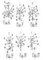
- FIG. 3 shows the automatic cycle starting with the state in which the blow mold 6 is closed.
- the continuously extruded from the extrusion die 5 of the extruder head 4 hose T is indicated by T.
- One of the two blowing mandrels 11 is retracted into the mouth 10 of the Blasformkavmaschine 7.
- Reference numeral 17 stands for the knife inactive in this state.
- the in Fig. 3 shown state is inflated in the Blasformkavtician hose according to the Blasformkavtician.
- the extruder head 4 is raised continuously and the vertical distance to the blow molding tool is continuously increased. This is in Fig.
- the end of the blowing process is in Fig. 5 indicated.
- the extruder head 4 is further removed from the blow molding tool 6 and is further raised.
- the inflated bottle located in the blow mold cavity 7 is vented by the blow mold 6.
- the hanging on the lower mandrel 11 bottle B is removed.
- the blow mold halves 8, 9 of the blow mold 6 are opened, which is in Fig. 6 is indicated.
- the extruder head 4 is still raised.
- the extruder head 4 is driven with the extruded tube piece T and thus connected, finished blown bottle B down in the direction of the blow mold 6.
- the blow mandrel 11 mounted on the mandrel holder 16 is also lowered.
- Figs. 6 and 7 is clearly seen that the extruded tube T is held even when the blow mold 6 is open in an axially defined position. Because the hose is still connected to the finished blown container B, the hose is fixed on the one hand by the extrusion nozzle 6 and on the other hand by the blowing mandrel 11. As a result, oscillation of the tube T is reliably prevented.
- the lowering speed of the extrusion head 4 and the mandrel 11 is advantageously synchronous and at least equal to the extrusion speed of the tube T. By a predetermined difference in the lowering speeds of the continuously extruded tube T can be stretched to the desired extent.
- the axially aligned arrangement of the extruder head 4, the blow molding tool 6 and the mandrel 6 also allows a relatively simple control of the axial movement components.
- the exit velocity of the plastic tube T, the movement of the mandrel 11 and an adjustment of the width of the extrusion die 5 are adjusted individually and coordinated with each other. This allows the implementation of optimized motion sequences, which are tailored to the requirements of the container to be blown B, without having to make changes to the overall concept of the axially aligned method.
- Fig. 8 shows the state in which the mandrel holder 16 has reached its lowest position. Now, the halves of the blow mold 6 are closed again to enclose a new tube section in the mold cavity. Shortly before the blow molding tool 6 is completely closed, the knife 17 is delivered laterally to separate the finished blown bottle B from the protruding from the mouth of Blasformkavmaschine piece of waste. This is in Fig. 8 indicated by a double arrow. The extruder head 4 has meanwhile reversed its direction of movement and is raised again. After severing, the mandrel holder 16 is rotated to align the second mandrel 11 with the mouth of the mandrel cavity.
- Fig. 10 shows the state in which the rotation of the Blasdornhalterung 16 is completed and the mandrel 11 has reached its correct stroke position. Thereafter, it is retracted into the mouth 10 of the Blasformkavtician 7. The subsequent opening of the bottle to be inflated is calibrated. Already during the retraction of the mandrel 11 in the Blasformkavtician 7 can be started with the pre-blowing. The extruder head 4 is thereby raised further. In Fig. 11 the mandrel 11 is finally retracted into the Blasdornkavmaschine the blow mold 6 and the production cycle starts again from the beginning.
- the representation in Fig. 11 corresponds to the representation in Fig. 3 ,
- the invention has been explained using the example of a continuous extrusion blow molding process and a corresponding device with a vertical arrangement of the extruder head, the blow molding tool and the blowing mandrels. It is understood that the arrangement of the device components can also take place in horizontal or any orientation according to the extrusion direction.
- the process according to the invention can also be used in a batch extrusion blow molding process and, accordingly, a discontinuous extrusion blow molding machine can also be produced.
- the key factors in the batch process are equally the provision of hose holding means on either side of the blow mold assembly and the order of extrusion die assembly, blow mold assembly and blow mandrel assembly.
- Essential to the invention is the fact that the extruded tube is held in a controllable position during an entire production cycle and the tube is separated only after the inflation and removal of the container.
- the separation point is located on the side facing away from the extruder head of Blasformwerkmaschinegneanix.
Claims (25)
- Procédé de fabrication de corps creux, en particulier de bouteilles en matière plastique, pour lequel une section d'un tuyau en matière plastique (T) est mise en place dans une cavité (7) d'un arrangement d'outil de moulage par soufflage (6) par une tête d'extrudeuse (4) à une cadence qui peut être prédéfinie, le tuyau en matière plastique (T) est soufflé par surpression selon la cavité du moule de soufflage (7) et le corps creux (B) est démoulé, le tuyau en matière plastique (T) étant maintenu continuellement pendant tout un cycle d'extrusion et de soufflage sur des côtés opposés l'un à l'autre de l'arrangement d'outil de moulage par soufflage (6) et étant détaché sur le côté de l'arrangement d'outil de soufflage (6) qui est détourné de la tête d'extrudeuse (4), caractérisé en ce que le tuyau en matière plastique (T) est fixé par la tête d'extrudeuse (4) et un mandrin de soufflage (11), l'outil de moulage par soufflage étant ouvert, lequel mandrin de soufflage (11) peut être introduit, pour insuffler le tuyau en matière plastique (T), dans une embouchure de la cavité du moule de soufflage (7) qui est placée sur le côté de l'arrangement d'outil de moulage par soufflage (6) qui est détourné de la tête d'extrudeuse (4).
- Procédé selon la revendication 1, caractérisé en ce que le tuyau en matière plastique (T) est détaché après le soufflage et le démoulage du corps creux (B) sur le côté de l'arrangement d'outil de soufflage (6) qui est détourné de la tête d'extrudeuse (4).
- Procédé selon la revendication 1, caractérisé en ce que deux ou plusieurs mandrins de soufflage (11) qui sont introduits en alternance dans la cavité du moule de soufflage (7) sont prévus pour chaque cavité du moule de soufflage (7).
- Procédé selon la revendication 3, caractérisé en ce que deux ou plusieurs mandrins de soufflage (11) sont prévus pour la cavité du moule de soufflage (7), mandrins qui sont fixés sur un support central de mandrins de soufflage (16) de telle manière qu'ils sont mis en oeuvre l'un après l'autre par rotation du support de mandrins de soufflage (16).
- Procédé selon la revendication 3 ou 4, caractérisé en ce que chaque mandrin de soufflage (11) est pourvu d'un dispositif de calibrage avec lequel l'ouverture du corps creux soufflé (B) est calibrée pendant l'opération de soufflage.
- Procédé selon l'une des revendications précédentes, caractérisé en ce que le tuyau en matière plastique est extrudé en continu et qu'après le transfert du tuyau en matière plastique extrudé (T) à la cavité du moule de soufflage (7) et pendant l'opération de soufflage la distance relative entre la tête d'extrudeuse (4) et l'arrangement d'outil de moulage par soufflage (6) est agrandie.
- Procédé selon la revendication 6, caractérisé en ce que l'agrandissement de la distance se fait en écartant la tête d'extrudeuse (4) de l'arrangement d'outil de moulage par soufflage (6) qui est substantiellement stationnaire pour ce qui est de sa position.
- Procédé selon la revendication 6 ou 7, caractérisé en ce que l'agrandissement de la distance se fait avec une vitesse qui est égale ou supérieure à une vitesse de sortie du tuyau en matière plastique de la tuyère d'extrusion (5) de la tête d'extrudeuse (4).
- Procédé selon l'une des revendications 1 à 5, caractérisé en ce que la tête d'extrudeuse est configurée comme une tête de retenue avec une tuyère d'extrudeuse avec laquelle le tuyau en matière plastique est éjecté en discontinu dans la cavité du moule de soufflage de l'arrangement d'outil de moulage par soufflage (6) et que la distance relative du mandrin de soufflage est agrandie par la tête de retenue pendant l'éjection du tuyau en matière plastique.
- Procédé selon la revendication 9, caractérisé en ce que la vitesse de l'agrandissement de la distance du mandrin de soufflage par la tête de retenue est égale ou supérieure à la vitesse d'éjection du tuyau en matière plastique hors de la tuyère d'extrusion.
- Procédé selon l'une des revendications précédentes, caractérisé en ce que le tuyau en matière plastique est incliné par rapport à son sens d'extrusion pendant le cycle de fabrication.
- Procédé selon l'une des revendications précédentes, caractérisé en ce que l'arrangement d'outil de moulage par soufflage (6) comprend au moins deux parties d'outil (8, 9) qui peuvent être séparées l'une de l'autre qui sont déplacées pour ouvrir et fermer l'outil de moulage par soufflage (6) essentiellement de manière perpendiculaire au sens de l'extrusion du tuyau en matière plastique d'une position terminale ouverte à une position terminale fermée et vice-versa.
- Procédé selon l'une des revendications précédentes, caractérisé en ce qu'une tête d'extrudeuse (4) avec un outil de tuyère d'extrusion multiple est utilisée, qu'un arrangement d'outil de moulage par soufflage (6) est utilisé qui est équipé d'un nombre correspondant de cavités de moule de soufflage (7) et qu'il est prévu un nombre de mandrins de soufflage (11) qui, de préférence, est le simple ou le multiple du nombre de cavités du moule de soufflage (7) et qui peuvent être introduites dans les embouchures des cavités du moule de soufflage (7) pour souffler les tuyaux en matière plastique (T).
- Procédé selon l'une des revendications précédentes, caractérisé en ce que la vitesse de sortie du tuyau en matière plastique, le mouvement de la tête d'extrudeuse, le mouvement du mandrin de soufflage, un mouvement d'ajustage de la largeur de la tuyère d'extrusion et le mouvement d'ouverture et de fermeture de l'arrangement d'outil de moulage par soufflage (6) peuvent être réglés individuellement et en étant adaptés l'un par rapport à l'autre.
- Dispositif pour la fabrication de corps creux (B), en particulier de bouteilles en matière plastique, avec une tête d'extrudeuse (4) avec une tuyère d'extrusion (5), tête d'extrusion placée dans un bâti d'appareil, un arrangement d'outil de moulage par soufflage (6) avec une cavité de moule de soufflage (7), avec au moins un dispositif de séparation (17) pour le tuyau en matière plastique (T), la tête d'extrudeuse formant, sur un côté de l'arrangement d'outil de moulage par soufflage (6), un premier dispositif de maintien pour le tuyau en matière plastique et qu'il est prévu, sur un côté opposé de l'arrangement d'outil de moulage par soufflage (6), un second dispositif de maintien pour le tuyau en matière plastique (T) et le dispositif de séparation étant placé sur le côté de l'arrangement d'outil de moulage par soufflage (6) qui est détourné de la tête d'extrudeuse (4), caractérisé en ce que le second dispositif de maintien pour le tuyau en matière plastique (T) est un mandrin de soufflage (11) et que la cavité de moule de soufflage (7) présente, sur le côté détourné de la tête d'extrudeuse (4), une ouverture d'embouchure dans laquelle le mandrin de soufflage (11) peut être introduit.
- Dispositif selon la revendication 15, caractérisé en ce que deux ou plusieurs mandrins de soufflage (11), qui peuvent être introduits en alternance dans la cavité de moule de soufflage (7), sont prévus pour chaque cavité de moule de soufflage (7).
- Dispositif selon la revendication 16, caractérisé en ce que les mandrins de soufflage (11) sont montés sur un support central de mandrins de soufflage (16) et peuvent être mis en oeuvre l'un après l'autre par rotation du support de mandrins de soufflage (16).
- Dispositif selon l'une des revendications 15 à 17, caractérisé en ce que chaque mandrin de soufflage (11) est pourvu d'un dispositif de calibrage avec lequel l'ouverture du corps creux soufflé (B) peut être calibrée pendant l'opération de soufflage.
- Dispositif selon l'une des revendications 15 à 18, caractérisé en ce que des moyens d'ajustage sont prévus avec lesquels la distance relative entre la tête d'extrudeuse (4) de l'arrangement d'outil de moulage par soufflage (6) peut être réglée pendant un cycle de fabrication.
- Dispositif selon la revendication 19, caractérisé en ce que les moyens d'ajustage sont reliés à la tête d'extrudeuse (4).
- Dispositif selon l'une des revendications 15 à 20, caractérisé en ce que la tête d'extrudeuse (4) est configurée pour une extrusion continue du tuyau en matière plastique (7).
- Dispositif selon l'une des revendications 15 à 20, caractérisé en ce que la tête d'extrudeuse est configurée comme une tête de retenue pour l'éjection discontinue du tuyau en matière plastique et que le mandrin de soufflage qui existe au moins est réglable en écartement par rapport à l'arrangement d'outil de moulage par soufflage (6) au moins avec la vitesse d'éjection du tuyau en matière plastique.
- Dispositif selon l'une des revendications 15 à 22, caractérisé en ce que la tête d'extrudeuse (4) présente une tuyère d'extrusion (5) substantiellement orientée verticalement et l'arrangement d'outil de moulage par soufflage (6) ainsi que le mandrin de soufflage qui existe au moins (11) sont placés l'un en dessous de l'autre verticalement.
- Dispositif selon l'une des revendications 15 à 23, caractérisé en ce que l'arrangement d'outil de moulage par soufflage (6) comprend au moins deux parties moulées (8, 9) pouvant être séparées l'une de l'autre qui peuvent être déplacées, pour l'ouverture et la fermeture, substantiellement perpendiculairement au sens d'extrusion du tuyau en matière plastique (T) d'une position terminale ouverte à une position terminale fermée et vice-versa.
- Dispositif selon l'une des revendications 16 à 27, caractérisé en ce qu'une tête d'extrudeuse (4) présente plusieurs tuyères d'extrusion (5), l'arrangement d'outil de moulage par soufflage (6) est équipé d'un nombre correspondant de cavités de moule de soufflage (7) et il est prévu un nombre de mandrins de soufflage (11) qui est le simple ou le multiple du nombre de cavités de moule de soufflage (7).
Priority Applications (1)
| Application Number | Priority Date | Filing Date | Title |
|---|---|---|---|
| SI200431326T SI1599330T1 (sl) | 2003-03-05 | 2004-01-29 | Postopek in naprava za izdelovanje votlih teles |
Applications Claiming Priority (5)
| Application Number | Priority Date | Filing Date | Title |
|---|---|---|---|
| CH3412003 | 2003-03-05 | ||
| CH341032003 | 2003-03-05 | ||
| CH517032003 | 2003-03-25 | ||
| CH5172003 | 2003-03-25 | ||
| PCT/CH2004/000047 WO2004078457A1 (fr) | 2003-03-05 | 2004-01-29 | Procede et dispositif pour fabriquer des corps creux |
Publications (2)
| Publication Number | Publication Date |
|---|---|
| EP1599330A1 EP1599330A1 (fr) | 2005-11-30 |
| EP1599330B1 true EP1599330B1 (fr) | 2009-11-04 |
Family
ID=32963141
Family Applications (1)
| Application Number | Title | Priority Date | Filing Date |
|---|---|---|---|
| EP04706117A Expired - Lifetime EP1599330B1 (fr) | 2003-03-05 | 2004-01-29 | Procede et dispositif pour fabriquer des corps creux |
Country Status (14)
| Country | Link |
|---|---|
| US (2) | US7837926B2 (fr) |
| EP (1) | EP1599330B1 (fr) |
| AT (1) | ATE447475T1 (fr) |
| BR (1) | BRPI0408663B1 (fr) |
| CA (1) | CA2517389C (fr) |
| DE (1) | DE502004010319D1 (fr) |
| ES (1) | ES2336105T3 (fr) |
| HR (1) | HRP20050671B1 (fr) |
| MX (1) | MXPA05009337A (fr) |
| PL (1) | PL211012B1 (fr) |
| PT (1) | PT1599330E (fr) |
| RU (1) | RU2305033C2 (fr) |
| SI (1) | SI1599330T1 (fr) |
| WO (1) | WO2004078457A1 (fr) |
Families Citing this family (7)
| Publication number | Priority date | Publication date | Assignee | Title |
|---|---|---|---|---|
| DE102004050845B3 (de) * | 2004-10-18 | 2006-02-23 | Bekum Maschinenfabriken Gmbh | Kalibrierverriegelung |
| ITBS20060113A1 (it) * | 2006-05-25 | 2007-11-26 | Barbara Grasselli | Procedimento per la produzione di un dispositivo urinario e dispositivo ottenuto. |
| DE102007050692B4 (de) * | 2007-10-22 | 2013-07-04 | Krones Aktiengesellschaft | Verfahren und Anordnung zum Herstellen eines Blasformwerkzeugs |
| CH702690B1 (de) * | 2008-01-11 | 2011-08-31 | Soplar Sa | Extrusionsblasvorrichtung und Verfahren zur Herstellung von Kunststoffbehältern. |
| EP2558272A4 (fr) * | 2010-04-12 | 2013-09-04 | Pro Technical Plastic Mfg Solutions Pty Ltd | Machine de moulage par soufflage et procédé de moulage par soufflage |
| CN107498829B (zh) * | 2017-08-24 | 2023-08-15 | 开平雅琪塑胶机械模具厂 | 一种机头摆动双工位机 |
| DE102020004564A1 (de) * | 2020-07-28 | 2022-02-03 | Kocher-Plastik Maschinenbau Gmbh | Vorrichtung und Verfahren zum Herstellen von Kunststoffbehältnissen |
Citations (1)
| Publication number | Priority date | Publication date | Assignee | Title |
|---|---|---|---|---|
| NL278810A (fr) * |
Family Cites Families (16)
| Publication number | Priority date | Publication date | Assignee | Title |
|---|---|---|---|---|
| NL54032C (fr) * | 1938-05-13 | 1900-01-01 | ||
| US2928120A (en) * | 1955-12-20 | 1960-03-15 | American Can Co | Process and apparatus for the manufacture of hollow articles |
| US3075239A (en) * | 1958-02-11 | 1963-01-29 | Shipton & Company Ltd E | Manufacture of hollow articles from organic plastic materials |
| US3003187A (en) * | 1958-10-16 | 1961-10-10 | Owens Illinois Glass Co | Method and apparatus for forming and trimming hollow plastic articles |
| US2988776A (en) * | 1959-07-27 | 1961-06-20 | Owens Illinois Glass Co | Method and apparatus for trimming blown hollow plastic articles |
| BE603955A (fr) * | 1960-05-18 | |||
| US2994103A (en) * | 1960-05-26 | 1961-08-01 | Owens Illinois Glass Co | Method and apparatus for trimming blown plastic articles |
| GB925775A (en) * | 1961-03-07 | 1963-05-08 | Shipton & Co Engineering Ltd E | Method of and apparatus for manufacturing blown hollow articles from organic plastic material |
| US3115673A (en) * | 1961-05-02 | 1963-12-31 | Purex Corp Ltd | Method and apparatus for blow molding plastic objects |
| NL302513A (fr) * | 1963-02-14 | 1900-01-01 | ||
| CH397224A (de) * | 1963-02-16 | 1965-08-15 | Kautex Werke Gmbh | Vorrichtung zur Herstellung von Hohlkörpern aus thermoplastischem Material |
| US3311684A (en) * | 1963-09-03 | 1967-03-28 | Owens Illinois Inc | Method for blow molding thermoplastic articles |
| US4155696A (en) * | 1975-02-28 | 1979-05-22 | Societe Anonyme Dite Compagnie Francaise De Raffinage | Apparatus for blow molding |
| DE3704264A1 (de) * | 1987-02-12 | 1988-08-25 | Ossberger Turbinen | Vorrichtung zum herstellen eines einerends offenen und anderenends geschlossenen kunststoff-hohlkoerpers |
| ATE116902T1 (de) * | 1991-08-08 | 1995-01-15 | Ossberger Turbinen | Vorrichtung zum herstellen eines vorformlings zum blasformen eines faltenbalges. |
| EP1377430B1 (fr) | 2001-04-10 | 2005-08-10 | Soplar Sa | Dispositif de production de corps creux en matiere plastique selon le procede d'extrusion-soufflage |
-
2004
- 2004-01-29 ES ES04706117T patent/ES2336105T3/es not_active Expired - Lifetime
- 2004-01-29 PL PL377659A patent/PL211012B1/pl unknown
- 2004-01-29 MX MXPA05009337A patent/MXPA05009337A/es active IP Right Grant
- 2004-01-29 RU RU2005130770/12A patent/RU2305033C2/ru active
- 2004-01-29 WO PCT/CH2004/000047 patent/WO2004078457A1/fr active Application Filing
- 2004-01-29 SI SI200431326T patent/SI1599330T1/sl unknown
- 2004-01-29 BR BRPI0408663-5A patent/BRPI0408663B1/pt not_active IP Right Cessation
- 2004-01-29 EP EP04706117A patent/EP1599330B1/fr not_active Expired - Lifetime
- 2004-01-29 AT AT04706117T patent/ATE447475T1/de active
- 2004-01-29 PT PT04706117T patent/PT1599330E/pt unknown
- 2004-01-29 DE DE502004010319T patent/DE502004010319D1/de not_active Expired - Lifetime
- 2004-01-29 CA CA002517389A patent/CA2517389C/fr not_active Expired - Lifetime
- 2004-01-29 US US10/547,192 patent/US7837926B2/en active Active
-
2005
- 2005-07-22 HR HR20050671 patent/HRP20050671B1/xx not_active IP Right Cessation
-
2010
- 2010-09-03 US US12/875,162 patent/US8496467B2/en active Active
Patent Citations (1)
| Publication number | Priority date | Publication date | Assignee | Title |
|---|---|---|---|---|
| NL278810A (fr) * |
Also Published As
| Publication number | Publication date |
|---|---|
| RU2305033C2 (ru) | 2007-08-27 |
| WO2004078457A1 (fr) | 2004-09-16 |
| DE502004010319D1 (de) | 2009-12-17 |
| EP1599330A1 (fr) | 2005-11-30 |
| US20060231986A1 (en) | 2006-10-19 |
| PT1599330E (pt) | 2010-01-29 |
| CA2517389A1 (fr) | 2004-09-16 |
| CA2517389C (fr) | 2009-01-27 |
| HRP20050671A2 (en) | 2005-10-31 |
| US8496467B2 (en) | 2013-07-30 |
| BRPI0408663B1 (pt) | 2014-10-07 |
| PL377659A1 (pl) | 2006-02-06 |
| HRP20050671B1 (en) | 2013-01-31 |
| ES2336105T3 (es) | 2010-04-08 |
| US20100330219A1 (en) | 2010-12-30 |
| MXPA05009337A (es) | 2005-11-04 |
| ATE447475T1 (de) | 2009-11-15 |
| US7837926B2 (en) | 2010-11-23 |
| SI1599330T1 (sl) | 2010-03-31 |
| PL211012B1 (pl) | 2012-03-30 |
| BRPI0408663A (pt) | 2006-03-28 |
| RU2005130770A (ru) | 2006-02-10 |
Similar Documents
| Publication | Publication Date | Title |
|---|---|---|
| EP1761376B1 (fr) | Procede de fabrication et machine d'extrusion-soufflage de contenants en plastique | |
| EP2167302B1 (fr) | Procédé de fabrication de corps creux en matière synthétique thermoplastique, dispositif associé et récipient en matière synthétique ainsi fabriqué | |
| DE2825866A1 (de) | Verfahren und vorrichtung zur herstellung von molekular orientierten kunststoff-flaschen | |
| EP1377430B1 (fr) | Dispositif de production de corps creux en matiere plastique selon le procede d'extrusion-soufflage | |
| DE2604247B2 (de) | Vorrichtung zur Herstellung mehrschichtiger Vorformlinge | |
| EP1599330B1 (fr) | Procede et dispositif pour fabriquer des corps creux | |
| DE2732978A1 (de) | Verfahren und vorrichtung zur herstellung hohler gegenstaende aus aushaertbaren, plastifizierten stoffen durch blasgiessen | |
| EP2227369B1 (fr) | Dispositif d'extrusion-soufflage et procédé de fabrication de récipients en matière plastique | |
| EP1884342A2 (fr) | Dispositif et procédé destinés à la fabrication de corps creux à partir de matières synthétiques thermoplastiques dans un procédé de soufflage | |
| EP2155468B1 (fr) | Machine de moulage-soufflage par extrusion et procédé de fabrication d'un corps creux en matière plastique | |
| DE1038750B (de) | Verfahren und Vorrichtung zur Herstellung von Flaschen oder aehnlichen Hohlkoerpern aus organischen thermoplastischen Kunststoffen | |
| EP2730390B1 (fr) | Procédé de calibrage d'une ouverture d'un récipient, qui est produite par un procédé d'extrusion soufflage | |
| DE3429141C2 (de) | Verfahren zur Herstellung eines Hohlkörpers | |
| EP1698445B1 (fr) | Procédé de moulage par soufflage de corps creux en matière thermoplastique | |
| DE19922490C2 (de) | Verfahren und Vorrichtung zum Herstellen von hohlkörperförmigen Artikeln aus thermoplastischem Kunststoff durch Saugblasen | |
| EP2310181B1 (fr) | Outil de moulage par soufflage comprenant plusieurs pièces pour fabriquer un corps creux, corps creux et machine d'extrusion-soufflage | |
| DE19528695A1 (de) | Verfahren und Vorrichtung zum Herstellen von Hohlkörpern aus thermoplastischem Kunststoff | |
| EP1129838B1 (fr) | Dispositif pour fabriquer des articles de forme creuse en matière thermoplastique par aspiration et soufflage | |
| EP1385689B1 (fr) | Tete d'extrusion pour la production d'un produit en matiere plastique sous forme de tuyau flexible ou rigide | |
| EP1048435A1 (fr) | Procédé et appareil de moulage par injection-soufflage | |
| DE2516798C3 (de) | Vorrichtung zum Herstellen von Hohlkörpern aus thermoplastischem Kunststoff | |
| DE2364663B2 (de) | Vorrichtung zum herstellen von hohlkoerpern aus thermoplastischem kunststoff im blasverfahren | |
| DE2607200A1 (de) | Vorrichtung zum herstellen von hohlkoerpern aus thermoplastischem kunststoff im blasverfahren | |
| DE3819129A1 (de) | Verfahren zur herstellung von kunststoff-flaschen sowie extrusions-blasformmaschine zur durchfuehrung des verfahrens | |
| DE2034777A1 (en) | Thermoplastic hollow bodies - using a ram core in a mould to shape the body by pressure |
Legal Events
| Date | Code | Title | Description |
|---|---|---|---|
| PUAI | Public reference made under article 153(3) epc to a published international application that has entered the european phase |
Free format text: ORIGINAL CODE: 0009012 |
|
| 17P | Request for examination filed |
Effective date: 20050720 |
|
| AK | Designated contracting states |
Kind code of ref document: A1 Designated state(s): AT BE BG CH CY CZ DE DK EE ES FI FR GB GR HU IE IT LI LU MC NL PT RO SE SI SK TR |
|
| AX | Request for extension of the european patent |
Extension state: AL LT LV MK |
|
| DAX | Request for extension of the european patent (deleted) | ||
| 17Q | First examination report despatched |
Effective date: 20080423 |
|
| R17C | First examination report despatched (corrected) |
Effective date: 20080423 |
|
| GRAP | Despatch of communication of intention to grant a patent |
Free format text: ORIGINAL CODE: EPIDOSNIGR1 |
|
| GRAS | Grant fee paid |
Free format text: ORIGINAL CODE: EPIDOSNIGR3 |
|
| GRAA | (expected) grant |
Free format text: ORIGINAL CODE: 0009210 |
|
| AK | Designated contracting states |
Kind code of ref document: B1 Designated state(s): AT BE BG CH CY CZ DE DK EE ES FI FR GB GR HU IE IT LI LU MC NL PT RO SE SI SK TR |
|
| REG | Reference to a national code |
Ref country code: GB Ref legal event code: FG4D Free format text: NOT ENGLISH |
|
| REG | Reference to a national code |
Ref country code: CH Ref legal event code: EP |
|
| REG | Reference to a national code |
Ref country code: IE Ref legal event code: FG4D |
|
| REF | Corresponds to: |
Ref document number: 502004010319 Country of ref document: DE Date of ref document: 20091217 Kind code of ref document: P |
|
| REG | Reference to a national code |
Ref country code: CH Ref legal event code: NV Representative=s name: RIEDERER HASLER & PARTNER PATENTANWAELTE AG |
|
| REG | Reference to a national code |
Ref country code: PT Ref legal event code: SC4A Free format text: AVAILABILITY OF NATIONAL TRANSLATION Effective date: 20100125 |
|
| REG | Reference to a national code |
Ref country code: GR Ref legal event code: EP Ref document number: 20100400170 Country of ref document: GR |
|
| REG | Reference to a national code |
Ref country code: ES Ref legal event code: FG2A Ref document number: 2336105 Country of ref document: ES Kind code of ref document: T3 |
|
| PG25 | Lapsed in a contracting state [announced via postgrant information from national office to epo] |
Ref country code: FI Free format text: LAPSE BECAUSE OF FAILURE TO SUBMIT A TRANSLATION OF THE DESCRIPTION OR TO PAY THE FEE WITHIN THE PRESCRIBED TIME-LIMIT Effective date: 20091104 Ref country code: SE Free format text: LAPSE BECAUSE OF FAILURE TO SUBMIT A TRANSLATION OF THE DESCRIPTION OR TO PAY THE FEE WITHIN THE PRESCRIBED TIME-LIMIT Effective date: 20091104 |
|
| REG | Reference to a national code |
Ref country code: SK Ref legal event code: T3 Ref document number: E 6735 Country of ref document: SK |
|
| REG | Reference to a national code |
Ref country code: IE Ref legal event code: FD4D |
|
| PG25 | Lapsed in a contracting state [announced via postgrant information from national office to epo] |
Ref country code: CY Free format text: LAPSE BECAUSE OF FAILURE TO SUBMIT A TRANSLATION OF THE DESCRIPTION OR TO PAY THE FEE WITHIN THE PRESCRIBED TIME-LIMIT Effective date: 20091104 |
|
| REG | Reference to a national code |
Ref country code: HU Ref legal event code: AG4A Ref document number: E007327 Country of ref document: HU |
|
| PG25 | Lapsed in a contracting state [announced via postgrant information from national office to epo] |
Ref country code: DK Free format text: LAPSE BECAUSE OF FAILURE TO SUBMIT A TRANSLATION OF THE DESCRIPTION OR TO PAY THE FEE WITHIN THE PRESCRIBED TIME-LIMIT Effective date: 20091104 Ref country code: BG Free format text: LAPSE BECAUSE OF FAILURE TO SUBMIT A TRANSLATION OF THE DESCRIPTION OR TO PAY THE FEE WITHIN THE PRESCRIBED TIME-LIMIT Effective date: 20100204 Ref country code: RO Free format text: LAPSE BECAUSE OF FAILURE TO SUBMIT A TRANSLATION OF THE DESCRIPTION OR TO PAY THE FEE WITHIN THE PRESCRIBED TIME-LIMIT Effective date: 20091104 Ref country code: IE Free format text: LAPSE BECAUSE OF FAILURE TO SUBMIT A TRANSLATION OF THE DESCRIPTION OR TO PAY THE FEE WITHIN THE PRESCRIBED TIME-LIMIT Effective date: 20091104 Ref country code: EE Free format text: LAPSE BECAUSE OF FAILURE TO SUBMIT A TRANSLATION OF THE DESCRIPTION OR TO PAY THE FEE WITHIN THE PRESCRIBED TIME-LIMIT Effective date: 20091104 |
|
| BERE | Be: lapsed |
Owner name: SOPLAR SA Effective date: 20100131 |
|
| PG25 | Lapsed in a contracting state [announced via postgrant information from national office to epo] |
Ref country code: MC Free format text: LAPSE BECAUSE OF NON-PAYMENT OF DUE FEES Effective date: 20100131 |
|
| PLBE | No opposition filed within time limit |
Free format text: ORIGINAL CODE: 0009261 |
|
| STAA | Information on the status of an ep patent application or granted ep patent |
Free format text: STATUS: NO OPPOSITION FILED WITHIN TIME LIMIT |
|
| 26N | No opposition filed |
Effective date: 20100805 |
|
| PG25 | Lapsed in a contracting state [announced via postgrant information from national office to epo] |
Ref country code: BE Free format text: LAPSE BECAUSE OF NON-PAYMENT OF DUE FEES Effective date: 20100131 |
|
| PG25 | Lapsed in a contracting state [announced via postgrant information from national office to epo] |
Ref country code: LU Free format text: LAPSE BECAUSE OF NON-PAYMENT OF DUE FEES Effective date: 20100129 |
|
| REG | Reference to a national code |
Ref country code: CH Ref legal event code: NV Representative=s name: R. A. EGLI AND CO. PATENTANWAELTE, CH |
|
| REG | Reference to a national code |
Ref country code: CH Ref legal event code: PUE Owner name: ISP TECHNOLOGY AG, CH Free format text: FORMER OWNER: SOPLAR SA, CH |
|
| REG | Reference to a national code |
Ref country code: PT Ref legal event code: PC4A Owner name: ISP TECHNOLOGY AG, CH Effective date: 20140114 |
|
| REG | Reference to a national code |
Ref country code: DE Ref legal event code: R082 Ref document number: 502004010319 Country of ref document: DE Representative=s name: SCHWABE SANDMAIR MARX, DE |
|
| REG | Reference to a national code |
Ref country code: ES Ref legal event code: PC2A Owner name: ISP TECHNOLOGY AG Effective date: 20140212 |
|
| REG | Reference to a national code |
Ref country code: GB Ref legal event code: 732E Free format text: REGISTERED BETWEEN 20140123 AND 20140129 |
|
| REG | Reference to a national code |
Ref country code: FR Ref legal event code: TP Owner name: ISP TECHNOLOGY AG, CH Effective date: 20140210 |
|
| REG | Reference to a national code |
Ref country code: NL Ref legal event code: SD Effective date: 20140312 |
|
| REG | Reference to a national code |
Ref country code: DE Ref legal event code: R082 Ref document number: 502004010319 Country of ref document: DE Representative=s name: SCHWABE SANDMAIR MARX, DE Effective date: 20140217 Ref country code: DE Ref legal event code: R082 Ref document number: 502004010319 Country of ref document: DE Representative=s name: SCHWABE SANDMAIR MARX PATENTANWAELTE RECHTSANW, DE Effective date: 20140217 Ref country code: DE Ref legal event code: R081 Ref document number: 502004010319 Country of ref document: DE Owner name: ISP TECHNOLOGY AG, CH Free format text: FORMER OWNER: SOPLAR S.A., ALTSTAETTEN, CH Effective date: 20140217 |
|
| REG | Reference to a national code |
Ref country code: HU Ref legal event code: GB9C Owner name: ISP TECHNOLOGY AG, CH Free format text: FORMER OWNER(S): SOPLAR SA, CH |
|
| REG | Reference to a national code |
Ref country code: SI Ref legal event code: SP73 Owner name: ISP TECHNOLOGY AG; CH Effective date: 20140214 |
|
| REG | Reference to a national code |
Ref country code: SK Ref legal event code: PC4A Ref document number: E 6735 Country of ref document: SK Owner name: ISP TECHNOLOGY AG, ALSTAETTEN SG, CH Free format text: FORMER OWNER: SOPLAR SA, ALTSTAETTEN, CH Effective date: 20131218 |
|
| REG | Reference to a national code |
Ref country code: AT Ref legal event code: PC Ref document number: 447475 Country of ref document: AT Kind code of ref document: T Owner name: ISP TECHNOLOGY AG, CH Effective date: 20140505 |
|
| REG | Reference to a national code |
Ref country code: FR Ref legal event code: PLFP Year of fee payment: 13 |
|
| REG | Reference to a national code |
Ref country code: FR Ref legal event code: PLFP Year of fee payment: 14 |
|
| REG | Reference to a national code |
Ref country code: FR Ref legal event code: PLFP Year of fee payment: 15 |
|
| PGFP | Annual fee paid to national office [announced via postgrant information from national office to epo] |
Ref country code: GR Payment date: 20210120 Year of fee payment: 18 Ref country code: CZ Payment date: 20210129 Year of fee payment: 18 Ref country code: PT Payment date: 20210125 Year of fee payment: 18 Ref country code: NL Payment date: 20210120 Year of fee payment: 18 |
|
| PGFP | Annual fee paid to national office [announced via postgrant information from national office to epo] |
Ref country code: TR Payment date: 20210127 Year of fee payment: 18 Ref country code: SI Payment date: 20210121 Year of fee payment: 18 Ref country code: HU Payment date: 20210214 Year of fee payment: 18 |
|
| PGFP | Annual fee paid to national office [announced via postgrant information from national office to epo] |
Ref country code: SK Payment date: 20210129 Year of fee payment: 18 |
|
| REG | Reference to a national code |
Ref country code: NL Ref legal event code: MM Effective date: 20220201 |
|
| REG | Reference to a national code |
Ref country code: SK Ref legal event code: MM4A Ref document number: E 6735 Country of ref document: SK Effective date: 20220129 |
|
| PG25 | Lapsed in a contracting state [announced via postgrant information from national office to epo] |
Ref country code: SK Free format text: LAPSE BECAUSE OF NON-PAYMENT OF DUE FEES Effective date: 20220129 Ref country code: PT Free format text: LAPSE BECAUSE OF NON-PAYMENT OF DUE FEES Effective date: 20220729 Ref country code: NL Free format text: LAPSE BECAUSE OF NON-PAYMENT OF DUE FEES Effective date: 20220201 Ref country code: GR Free format text: LAPSE BECAUSE OF NON-PAYMENT OF DUE FEES Effective date: 20220805 Ref country code: CZ Free format text: LAPSE BECAUSE OF NON-PAYMENT OF DUE FEES Effective date: 20220129 |
|
| PG25 | Lapsed in a contracting state [announced via postgrant information from national office to epo] |
Ref country code: SI Free format text: LAPSE BECAUSE OF NON-PAYMENT OF DUE FEES Effective date: 20220130 |
|
| REG | Reference to a national code |
Ref country code: SI Ref legal event code: KO00 Effective date: 20220929 |
|
| PGFP | Annual fee paid to national office [announced via postgrant information from national office to epo] |
Ref country code: FR Payment date: 20230124 Year of fee payment: 20 Ref country code: ES Payment date: 20230330 Year of fee payment: 20 Ref country code: AT Payment date: 20230120 Year of fee payment: 20 |
|
| PGFP | Annual fee paid to national office [announced via postgrant information from national office to epo] |
Ref country code: IT Payment date: 20230120 Year of fee payment: 20 Ref country code: GB Payment date: 20230119 Year of fee payment: 20 Ref country code: DE Payment date: 20230123 Year of fee payment: 20 |
|
| PGFP | Annual fee paid to national office [announced via postgrant information from national office to epo] |
Ref country code: CH Payment date: 20230501 Year of fee payment: 20 |
|
| REG | Reference to a national code |
Ref country code: DE Ref legal event code: R071 Ref document number: 502004010319 Country of ref document: DE |
|
| REG | Reference to a national code |
Ref country code: CH Ref legal event code: PL |
|
| REG | Reference to a national code |
Ref country code: GB Ref legal event code: PE20 Expiry date: 20240128 |
|
| REG | Reference to a national code |
Ref country code: AT Ref legal event code: MK07 Ref document number: 447475 Country of ref document: AT Kind code of ref document: T Effective date: 20240129 |
|
| PG25 | Lapsed in a contracting state [announced via postgrant information from national office to epo] |
Ref country code: ES Free format text: LAPSE BECAUSE OF EXPIRATION OF PROTECTION Effective date: 20240130 |