EP1599330B1 - Method and device for the production of hollow bodies - Google Patents
Method and device for the production of hollow bodies Download PDFInfo
- Publication number
- EP1599330B1 EP1599330B1 EP04706117A EP04706117A EP1599330B1 EP 1599330 B1 EP1599330 B1 EP 1599330B1 EP 04706117 A EP04706117 A EP 04706117A EP 04706117 A EP04706117 A EP 04706117A EP 1599330 B1 EP1599330 B1 EP 1599330B1
- Authority
- EP
- European Patent Office
- Prior art keywords
- blow molding
- plastic tube
- extruder head
- blowing
- molding tool
- Prior art date
- Legal status (The legal status is an assumption and is not a legal conclusion. Google has not performed a legal analysis and makes no representation as to the accuracy of the status listed.)
- Expired - Lifetime
Links
- 238000000034 method Methods 0.000 title claims abstract description 64
- 238000004519 manufacturing process Methods 0.000 title claims abstract description 22
- 239000004033 plastic Substances 0.000 claims abstract description 105
- 229920003023 plastic Polymers 0.000 claims abstract description 105
- 238000001125 extrusion Methods 0.000 claims abstract description 90
- 238000000071 blow moulding Methods 0.000 claims description 113
- 238000007664 blowing Methods 0.000 claims description 78
- 230000033001 locomotion Effects 0.000 claims description 34
- 239000003000 extruded plastic Substances 0.000 claims description 9
- 238000000926 separation method Methods 0.000 claims description 7
- 238000012546 transfer Methods 0.000 claims description 3
- 238000010101 extrusion blow moulding Methods 0.000 description 16
- 239000000463 material Substances 0.000 description 6
- -1 drinks Substances 0.000 description 4
- 238000010923 batch production Methods 0.000 description 3
- 238000013461 design Methods 0.000 description 3
- 238000006073 displacement reaction Methods 0.000 description 3
- 230000010355 oscillation Effects 0.000 description 3
- 239000002699 waste material Substances 0.000 description 3
- 229920000426 Microplastic Polymers 0.000 description 2
- 238000010276 construction Methods 0.000 description 2
- 238000001816 cooling Methods 0.000 description 2
- 238000005520 cutting process Methods 0.000 description 2
- 238000002347 injection Methods 0.000 description 2
- 239000007924 injection Substances 0.000 description 2
- 238000000465 moulding Methods 0.000 description 2
- 238000012805 post-processing Methods 0.000 description 2
- 238000012545 processing Methods 0.000 description 2
- 230000001360 synchronised effect Effects 0.000 description 2
- 239000004698 Polyethylene Substances 0.000 description 1
- 239000004743 Polypropylene Substances 0.000 description 1
- 238000009825 accumulation Methods 0.000 description 1
- 239000000919 ceramic Substances 0.000 description 1
- 238000004140 cleaning Methods 0.000 description 1
- 239000002537 cosmetic Substances 0.000 description 1
- 230000007423 decrease Effects 0.000 description 1
- 230000001419 dependent effect Effects 0.000 description 1
- 238000011161 development Methods 0.000 description 1
- 230000018109 developmental process Effects 0.000 description 1
- 238000010586 diagram Methods 0.000 description 1
- 230000000694 effects Effects 0.000 description 1
- 238000002474 experimental method Methods 0.000 description 1
- 230000002349 favourable effect Effects 0.000 description 1
- 239000012530 fluid Substances 0.000 description 1
- 239000011521 glass Substances 0.000 description 1
- 230000005484 gravity Effects 0.000 description 1
- 230000004886 head movement Effects 0.000 description 1
- 230000014759 maintenance of location Effects 0.000 description 1
- 238000004806 packaging method and process Methods 0.000 description 1
- 239000013502 plastic waste Substances 0.000 description 1
- 229920000573 polyethylene Polymers 0.000 description 1
- 229920001155 polypropylene Polymers 0.000 description 1
- 238000004886 process control Methods 0.000 description 1
- 238000007665 sagging Methods 0.000 description 1
- 238000010008 shearing Methods 0.000 description 1
- 239000000243 solution Substances 0.000 description 1
- 230000000087 stabilizing effect Effects 0.000 description 1
- 239000000126 substance Substances 0.000 description 1
- 238000006467 substitution reaction Methods 0.000 description 1
- 230000008961 swelling Effects 0.000 description 1
Images


Classifications
-
- B—PERFORMING OPERATIONS; TRANSPORTING
- B29—WORKING OF PLASTICS; WORKING OF SUBSTANCES IN A PLASTIC STATE IN GENERAL
- B29C—SHAPING OR JOINING OF PLASTICS; SHAPING OF MATERIAL IN A PLASTIC STATE, NOT OTHERWISE PROVIDED FOR; AFTER-TREATMENT OF THE SHAPED PRODUCTS, e.g. REPAIRING
- B29C49/00—Blow-moulding, i.e. blowing a preform or parison to a desired shape within a mould; Apparatus therefor
- B29C49/02—Combined blow-moulding and manufacture of the preform or the parison
- B29C49/04—Extrusion blow-moulding
-
- B—PERFORMING OPERATIONS; TRANSPORTING
- B29—WORKING OF PLASTICS; WORKING OF SUBSTANCES IN A PLASTIC STATE IN GENERAL
- B29C—SHAPING OR JOINING OF PLASTICS; SHAPING OF MATERIAL IN A PLASTIC STATE, NOT OTHERWISE PROVIDED FOR; AFTER-TREATMENT OF THE SHAPED PRODUCTS, e.g. REPAIRING
- B29C2793/00—Shaping techniques involving a cutting or machining operation
- B29C2793/009—Shaping techniques involving a cutting or machining operation after shaping
-
- B—PERFORMING OPERATIONS; TRANSPORTING
- B29—WORKING OF PLASTICS; WORKING OF SUBSTANCES IN A PLASTIC STATE IN GENERAL
- B29C—SHAPING OR JOINING OF PLASTICS; SHAPING OF MATERIAL IN A PLASTIC STATE, NOT OTHERWISE PROVIDED FOR; AFTER-TREATMENT OF THE SHAPED PRODUCTS, e.g. REPAIRING
- B29C49/00—Blow-moulding, i.e. blowing a preform or parison to a desired shape within a mould; Apparatus therefor
- B29C49/22—Blow-moulding, i.e. blowing a preform or parison to a desired shape within a mould; Apparatus therefor using multilayered preforms or parisons
-
- B—PERFORMING OPERATIONS; TRANSPORTING
- B29—WORKING OF PLASTICS; WORKING OF SUBSTANCES IN A PLASTIC STATE IN GENERAL
- B29C—SHAPING OR JOINING OF PLASTICS; SHAPING OF MATERIAL IN A PLASTIC STATE, NOT OTHERWISE PROVIDED FOR; AFTER-TREATMENT OF THE SHAPED PRODUCTS, e.g. REPAIRING
- B29C49/00—Blow-moulding, i.e. blowing a preform or parison to a desired shape within a mould; Apparatus therefor
- B29C49/28—Blow-moulding apparatus
-
- B—PERFORMING OPERATIONS; TRANSPORTING
- B29—WORKING OF PLASTICS; WORKING OF SUBSTANCES IN A PLASTIC STATE IN GENERAL
- B29C—SHAPING OR JOINING OF PLASTICS; SHAPING OF MATERIAL IN A PLASTIC STATE, NOT OTHERWISE PROVIDED FOR; AFTER-TREATMENT OF THE SHAPED PRODUCTS, e.g. REPAIRING
- B29C49/00—Blow-moulding, i.e. blowing a preform or parison to a desired shape within a mould; Apparatus therefor
- B29C49/42—Component parts, details or accessories; Auxiliary operations
- B29C49/48—Moulds
-
- B—PERFORMING OPERATIONS; TRANSPORTING
- B29—WORKING OF PLASTICS; WORKING OF SUBSTANCES IN A PLASTIC STATE IN GENERAL
- B29C—SHAPING OR JOINING OF PLASTICS; SHAPING OF MATERIAL IN A PLASTIC STATE, NOT OTHERWISE PROVIDED FOR; AFTER-TREATMENT OF THE SHAPED PRODUCTS, e.g. REPAIRING
- B29C49/00—Blow-moulding, i.e. blowing a preform or parison to a desired shape within a mould; Apparatus therefor
- B29C49/42—Component parts, details or accessories; Auxiliary operations
- B29C49/76—Neck calibration
-
- B—PERFORMING OPERATIONS; TRANSPORTING
- B29—WORKING OF PLASTICS; WORKING OF SUBSTANCES IN A PLASTIC STATE IN GENERAL
- B29K—INDEXING SCHEME ASSOCIATED WITH SUBCLASSES B29B, B29C OR B29D, RELATING TO MOULDING MATERIALS OR TO MATERIALS FOR MOULDS, REINFORCEMENTS, FILLERS OR PREFORMED PARTS, e.g. INSERTS
- B29K2023/00—Use of polyalkenes or derivatives thereof as moulding material
- B29K2023/10—Polymers of propylene
- B29K2023/12—PP, i.e. polypropylene
Definitions
- the invention relates to a method for the production of hollow bodies according to the preamble of claim 1.
- the invention also relates to a device suitable for this purpose.
- plastic containers made of white or stained, glass or ceramic are increasingly being replaced by plastic containers.
- plastic containers are used for the packaging of fluid substances, such as drinks, oil, cleaning utensils, cosmetics, etc.
- the low weight and the lower costs certainly play a significant role in this substitution.
- the use of recyclable plastic materials and the overall more favorable overall energy balance in their production also contribute to the consumer's acceptance of plastic containers, in particular of plastic bottles.
- plastic containers in particular plastic bottles, for example made of polyethylene or polypropylene
- extrusion blow molding machines used for this purpose generally have at least one extruder for feeding the plastic material.
- the outlet of the extruder is connected to the extruder head, at the preferably in the opening width of the adjustable outlet nozzle, the one or more extruded extruded tube emerges.
- the extruded tube is transferred to a blow mold and inflated within the cavity with a blow pin.
- the plastic tube can be single-layered or multi-layered, it can be extruded as a tube with viewing strips, decorative strips or related to the circumference with several, for example, different colored segments.
- the blowing station with the mandrel is usually arranged laterally of the extrusion head, and the blow molding tool fed with the extruded tube must be moved into the blowing station, where then the mandrel is usually retracted from above into the Blasformkavtician.
- two blowing stations are usually provided in one type of known extrusion blow molding machines. Each blowing station is equipped with a blow molding tool.
- the blowing stations are arranged on both sides of the extruder, opposite each other and have blow molding with the blow molding tools, which are moved alternately under the extruder head to receive the extruded tube.
- the blow mold is opened to pick up the hose. After closing the blow molding tool, the tube between the extrusion head and the blow mold is separated.
- each blowing station is equipped with a corresponding number of blowing mandrels, which are inserted together into the blow molding cavities.
- the extruder with the extruder head and the two blowing stations form approximately the shape of a T.
- the extruder with the extruder head represents the long T-bar, while the two blow-molding tables are alternately movable along the short cross-half halves under the extruder head.
- Extrusion blow molding machines are also known, in which a number of blow molding tools are arranged on a rotating wheel.
- the wheel is approximately vertical and leads the blow molding approximately tangentially to the extruded from the extrusion head plastic hose.
- the introduced blow mold is opened to pick up the hose.
- the blow mold is closed around the inserted hose and this is finally sheared off as it rotates further.
- the arrangement of the blow molding tools and the rotational speed of the wheel are selected such that the hose is sheared off only when the subsequent blow molding tool has closed around the next piece of hose.
- the tube located in the cavity of the blow molding tool finally passes into the blowing station during further rotation of the wheel, where it is inflated via a blowing mandrel inserted laterally into the molding tool according to the blow molding cavity. Finally, the inflated hollow body is discharged by opening from the blow molding tool.
- the blow molding tool arranged on the rotating wheel is closed again during the further movement and brought back to the extrusion head in order to receive a further extruded hose.
- a disadvantage of the wheel blow molding machines is the fact that they require a relatively high capital outlay for the provision of the blow molding tools because of the large number of arranged on the wheel separate blow molds.
- the blow molds are not completely identical in the rule. This can lead from blow mold to blow mold to quality differences in the produced hollow bodies.
- the use of blow molds with multiple blow mold cavities is relatively difficult and expensive.
- the blow molds are only attachable to firmly fixed mounting points on the wheel. These are determined by the maximum height of the blown hollow body that can be produced by the machine. Once fixed mounting points are no longer changeable. This is also a consequence of the mechanical controls on control cams, cams and the like customary in these machines.
- an apparatus and method for making preforms of non-uniform wall thickness.
- Plastic is pressed into a neck shape to pour a neck of the vessel.
- the opening width of the extrusion head is widened and narrowed, thereby extruding a tubular plastic structure held in a collar shape and having different wall thicknesses between the collar shape and the extrusion head.
- the tubular plastic structure is inflated in a blow mold and separated directly on the extruder head.
- a method of continuously producing plastic containers and an apparatus suitable for such a method are known.
- the plastic tube is introduced from an extruder head into a cavity. With two pressed parts of the plastic tube is pressed together and closed and a bottom formed.
- an injection opening is provided, through which the plastic tube is inflated in the cavity.
- the container is then pulled out of the cavity during the blowing.
- the pressed parts are released from the plastic container and reintroduced into the cavity, in which a new piece of tubing is now present.
- the freshly blown container is grasped by a holder and pulled while the bottom piece is moved back into the cavity. Now the bottom piece presses the plastic tube together again and the inflation of the new bottle begins.
- the tube is further extruded and the pressed parts moved longitudinally in the cavity. The tube is therefore blown during extrusion and displaced within the cavity.
- the object of the present invention is therefore to avoid the disadvantages of the methods and devices of the prior art.
- a blow-molding process and an extrusion blow-molding machine are to be created which permit reliable processing of various plastic raw products.
- the design of the container geometries should be as many open spaces, and it should also be able to produce containers with very complex geometry with very tight specifications.
- the method and the device for extrusion blow molding of hollow bodies should be compatible for the production of large and small geometries. In doing so, unnecessary plastic waste should be largely avoided.
- the method and the device should be modified to the effect that, regardless of the number of cavities per blow mold largely identical container properties and quality parameters can be achieved.
- the adjustment data determined in the experiment should be largely transferable to production plants without any changes.
- the space requirement compared to existing machines should not be greater, yes it should even be possible to reduce this. Dead times, as they occur in the known machines in the lateral displacement of the blow molds in the blow molding stations, should be reduced.
- a section of a plastic tube is introduced into a cavity of a blow molding tool by an extruder head in a predeterminable cycle.
- the plastic tube is inflated via a mandrel by overpressure according to the Blasformkavtician.
- the finished blown hollow body is finally removed from the mold.
- the plastic tubing is continuously held on opposite sides of the blow molder assembly throughout an entire extrusion and blowing cycle.
- the plastic tube is continuous on opposite sides of the blow molding tool assembly during an entire production cycle, ie during an entire extrusion and blowing cycle held.
- the plastic tube is permanently guided and misplaced situations can be avoided.
- the condition is created to always introduce a extruded from an extrusion die hose in the same Blasformkavtician. All of the hollow bodies produced with an extrusion die-blow mold cavity arrangement thus experience the same setting and tool parameters. Differences in quality due to different sized tolerances of Blasformkavticianen omitted in arrangements with several different blow molds.
- Dead times which take place by a lateral displacement of the blow molding tool arrangement with respect to the extruder head, are dispensed with, since the blow mold arrangement is oriented substantially only in the transport direction of the plastic tube.
- the inflating of the plastic hose located in the blow mold cavity takes place immediately after the charging of the blow mold cavity with the extruded plastic hose.
- the plastic tube is held in a defined position during the entire extrusion and Blaszyklusses and can no longer oscillate about its axis.
- the extruder head and the blow molding tool remain in a predeterminable and adjustable, geometric positional relationship throughout the extrusion and blowing process, and the plastic tube can always be optimally adopted.
- the method according to the invention allows the position of the extruded plastic tube with respect to the blow mold cavity to be changed as required in order to take into account special geometrical requirements.
- the plastic tube is separated only after complete inflation of the hollow body.
- the separation can be done by controlled squeezing or by shearing.
- a separating knife or the like is used for this purpose.
- This variant of the method differs both from the blow molding process with the known wheel blow molding machines, in which the tube is sheared after uncontrolled after taking over the blow mold on further rotation of the wheel, as well as the continuous and discontinuous blow molding with known extrusion blow molding machines, in which Plastic hose in front of the actual blow process is controlled cut.
- the method according to the invention requires that the mandrel be synchronized for a certain time with the movement of the extruder head and / or the extrusion or transfer speed of the plastic tube to the blow molding tool arrangement.
- this simple measure ensures that the hose is kept controlled at every stage of the production cycle.
- the separation of the plastic tube is advantageously carried out on the side facing away from the extruder head of Blasformwerkmaschinemaschine fürssenssen. As a result, before the separation of the leadership of the hose on the blow spool located on the finished blown hollow body and the extruder head ensured.
- the separation point By arranging the separation point in the immediate vicinity of the mouth of Blasformkavtician the hose material waste can always be kept as small as possible regardless of the height of Blasformkavtician.
- the Blasformwerkmaschinemaschinenraum is disposed between the extruder head and the mandrel.
- the mandrel is retracted through an opening of the Blasformkavmaschine, which is arranged on the side facing away from the extrusion nozzle side of the Blasformwerkmaschinegnean ever.
- the outlet of the extrusion nozzle and the axial extension of the blowing mandrel are arranged such that they are aligned substantially axially.
- blowing mandrels are provided for reducing the dead times for each blow mold cavity.
- the blowing mandrels can for example be arranged side by side and be delivered alternately to the openings of the blow mold cavities.
- a plurality of blowing mandrels are attached to a central Blasdornhalterung such that they are used by rotation of the Blasdornhalterung successively used.
- the Blasdornhalterung can carry two mandrels, offset by 180 ° to each other.
- the blow mandrel holder is rotated by 180 ° after inflation of the tube and the opening of the blow mold assembly.
- the second mandrel is thus already ready for the inflation of another hose section, while the hollow body is still waiting for its removal at the first mandrel.
- rotatable Blasdornhalterept with 3, 4 or more Blasdornen can be provided.
- the angle by which the Blasdornhalterung must be further rotated, then results from the division of 360 ° by the number Blasdome.
- the arrangement on the side of the blow molding tool arrangement facing away from the extrusion nozzle also offers the possibility of providing each blowing mandrel with a calibrating device with which the opening of the blown hollow body is already calibrated during the blowing process. This eliminates a separate post-processing station, in which this process must be made up.
- the plastic tube is extruded continuously from the extrusion die of the extruder head.
- the relative distance of the extruder head from the blow molder assembly is increased to prevent it from starting against the surface of the blow molder assembly during further extrusion and to maintain the tube in a controlled orientation. This accounts for the fact that the plastic tubing is continuously extruded from the extrusion die while the inflation process in the mold cavity of the blow mold assembly is a discontinuous process.
- the relative change in distance between the extruder head and the blow mold arrangement takes place at least at a speed which corresponds to the exit speed of the plastic tube from the extrusion die. Thereby it is ensured that the extruded tube does not run on the surface of the blow mold arrangement.
- plastic tube is drawn as it were from the nozzle tool.
- the wall thickness of the extruded plastic tube can be selectively changed. It can thus be produced with a relatively large nozzle gap a thin-walled hose.
- the plastic tube is discontinuously ejected from the extrusion die of an extruder head designed as a stuffer head into the blow mold cavity. During the ejection of the plastic tube, the distance of the mandrel is increased by the jam head.
- the structure of the extrusion blow molding machine for the batch process largely corresponds to that of the continuous machines.
- the hose is permanently held during the production process and guided in a controlled manner. This prevents uncontrolled oscillation of the hose.
- the holding of the hose can also be used for a controlled stretching or change in position if necessary.
- the speed of the change in distance of the mandrel is set by the accumulation head equal to or greater than the ejection speed of the plastic tube from the extrusion die.
- the method according to the invention permits a process control with any direction of movement of the plastic tube. While the known methods are essentially limited to a vertical extrusion direction of the plastic tube, the guidance of the tube also allows an oblique, even a horizontal alignment. However, for compatibility with existing machines, axial alignment is preferred. An axially aligned arrangement of the extruder head, the blow mold assembly and the blow mandrel allows a relatively simple control of the axial movement components.
- This allows the implementation of optimized movements, which are tailored to the requirements of the container to be blown, without having to make changes to the overall concept of the inventive method.
- the plastic tube is inclined during a manufacturing cycle in order to be able to optimally serve special geometries of blow mold cavities and to produce special container geometries.
- the blow molding tool assembly comprises at least two separable moldings, which are moved to open and close the blow mold substantially perpendicular to the extrusion direction from an open end position to a closed end position and vice versa.
- it may be a blow molding tool which, in addition to the molded parts for constructing the container body, also has a lift-off bottom part.
- the actuating means for the opening and closing operation can likewise be arranged in a stationary manner. The absence of an additional movement component simplifies the mechanical structure and also helps to reduce the control effort for the controlled movements of the molded parts.
- the blow mold assembly may also be a single tool or an assembly of tools having one or more blow mold cavities coupled together.
- an extruder head with a multiple extrusion die tool and a blow molding tool arrangement are used which have a corresponding number is equipped by blow mold cavities.
- a number of Blasdornen is provided, which is one or more times the number Blasformkavticianen and can be retracted for inflating the plastic tubes in the mouths of Blasformkavticianen.
- a larger number of hollow bodies, for example plastic bottles can be produced in a blowing cycle with constant machine and tool parameters. Thereby, the throughput is increased, and the profitability of a multiple blow molding tool assembly can be further improved.
- the tubing is continuously held throughout the entire production cycle of a container. This creates the conditions for the use of a single Blasformkavtician per extrusion die. Dead times due to lateral movements of the blow molding tool device are avoided.
- the permanent guidance of the plastic tube prevents misplacements. If necessary, the position of the hose can also be changed in a targeted manner with respect to the extrusion direction. In this way, for example, the requirements of more complicated container geometries are taken into account. All of the hollow bodies made with an extrusion die blow mold assembly experience the same setting and tooling parameters. Differences in quality due to different sized tool tolerances in several different blow molds omitted.
- Dead times caused by a lateral shift the blow molding tool arrangement relative to the extruder head can be avoided, since the blow mold arrangement is oriented substantially only to the transport direction of the plastic tube.
- the inflating of the plastic hose located in the blow mold cavity takes place immediately after the charging of the blow mold cavity with the extruded plastic hose.
- the plastic tube is fixed in a defined position during the entire production cycle and can no longer oscillate about its axis.
- the extruder head and the blow mold assembly remain substantially in a predeterminable and adjustable geometrical positional relationship throughout the extrusion and blowing process, and the plastic tubing can always be optimally handled. As a result, the risk of unintentional trapping of the plastic tube is reduced even with more complicated geometries of Blasformkavtician.
- the holding devices for the hose are formed on the one hand by the mandrel and on the other hand by the extruder head.
- the blow molding tool assembly between the extruder head and the mandrel is arranged.
- the blow mold cavity has an orifice on the side of the blow molding tool arrangement facing away from the extrusion nozzle, into which the blowing mandrel can be inserted into the blow mold cavity.
- the adjusting and advancing movements of the device components are essentially limited to movements along the direction of movement of the plastic tube or substantially perpendicular. This leads to lower mechanical stresses and reduces the vibrations and vibrations that occur during operation.
- An embodiment of the invention provides for the Blasformkavtician two or more blowing mandrels, which are alternately deliverable.
- the blowing mandrels can for example be arranged next to one another and moved alternately into the correct position.
- the transport routes of the Blasdorne are very short.
- the dead times for the delivery of the mandrel can be kept short.
- An alternative variant provides that the blowing mandrels are mounted on a central Blasdornhalterung, and can be brought successively by rotation of the Blasdornhalterung used.
- the Blasdornhalterung can carry two mandrels, offset by 180 ° to each other.
- the blow mandrel holder is rotated by 180 ° after inflation of the tube and the opening of the blow mold.
- the second mandrel is thus already ready for the inflation of another hose section, while the hollow body is still waiting for its removal at the first mandrel.
- rotatable Blasdornhalterungen can be provided with 3, 4 or more Blasdornen. The angle at which the Blasdornhalterung must be further rotated in each case, then results from the division of 360 ° by the number of blowing mandrels.
- calibrating devices are provided on each blowing mandrel with which the opening of the blown hollow body can be calibrated during the blowing process.
- a time-consuming post-processing step can be omitted.
- adjusting means are provided with which the relative distance between the extruder head and the blow molding tool arrangement can be adjusted.
- the extruder head is connected to the adjusting means and is adjustable in distance relative to the stationary Blasformwerkmaschinegnean nie. This arrangement has the advantage that essentially only provisions for the opening and closing of the molded parts must be provided on the blow molding tool arrangement. This simplifies the motion sequences and the control effort.
- the extruder head can be designed for continuous extrusion of the plastic tube.
- the change in distance between the extruder head and the blow molding tool arrangement takes place at least at the extrusion speed of the plastic tube.
- the extruder head is designed as a stuffer head for the discontinuous ejection of the plastic tube.
- the mandrel is adjustable in distance at least with the ejection speed of the plastic tube relative to the Blasformwerkmaschinemaschineanix
- the alignment of the extrusion nozzle, the blow molding tool arrangement and the blowing mandrel (s) can be chosen as desired.
- the extruder head has a substantially vertically oriented extrusion die and the Blasformwerkmaschinen Aunt and the or the blowing mandrels are arranged vertically to each other.
- the vertical arrangement also takes advantage of the somewhat stabilizing effect of gravity on the extruded plastic tube.
- the blow molding tool arrangement comprises at least two mold parts which can be separated from one another and which are movable from an open end position into a closed end position and vice versa for opening and closing substantially perpendicular to the extrusion direction of the plastic hose.
- it may be a blow molding tool which, in addition to the molded parts for constructing the container body, also has a lift-off bottom part.
- the actuating means for the opening and closing operation can likewise be arranged in a stationary manner. The renunciation of an additional component of movement simplifies the mechanical design and also helps to reduce the control effort for the controlled movements of the molded parts.
- the extruder head has a plurality of extrusion nozzles and the Blasformwerkmaschinechtan himself is equipped with a corresponding number of Blasformkavmaschineen.
- a number of blowing mandrels is provided, which is one or more times the number Blasformkavmaschineen.
- a larger number of hollow bodies, such as plastic bottles can be generated with constant machine and tool parameters. This has advantages with regard to the uniformity of the quality of the products produced.
- Fig. 1 only shown in principle extrusion blow molding machine of the prior art is generally provided with the reference numeral 1.
- the construction of such long-stroke extrusion blow molding machines is well known and, for example, in "Blow molding handbook, edited by Donald V. Rosato and Dominick V. Rosato, 1989, ISBN 1-56990-089-2, Library of Congress Catalog Number 88-016270 " Fig. 1 Therefore, it is limited to the components of the extrusion blow molding machine 1 that are absolutely necessary for the understanding.
- it is a Zweistationenblasmaschine, as it is also offered by the applicant. It has an extrusion unit 2 and two blowing stations 12, 13.
- the extrusion unit 2 comprises an extruder 3 for plastic granules and an extruder head 4 connected thereto, which has at least one extrusion die 5.
- the blowing stations 12, 13 each have a blowing head with a blowing mandrel.
- Each blow station 12, 13 is equipped with a blow molding table 14, 15 in which blow molds 6 are mounted.
- the blow molding tools 6 each enclose a blow mold cavity 7, which corresponds to the shape of the hollow body to be produced, for example a bottle.
- the blow molding cavities 7 have an opening 8 on their upper side facing the extruder head 4.
- blow molding tables 14, 15 are alternately displaceable from their lateral end positions in the blowing stations 12, 13 into a position in which the mouth 8 of the blow molding tool 6 joins the outlet of the extrusion nozzle 5 axially aligned.
- the lateral displacement of the blow molding tables 14, 15 takes place substantially perpendicular to the longitudinal extension of the extruder 3.
- the supplied via the extruder 3 plastic granules are melted in the extruder 3 and / or in the extruder head 4 and extruded from the extrusion die 5 as an endless tube.
- the hose can be extruded one or more layers.
- other extruders may be provided which transport the required different plastic materials to the extruder head 4.
- the blow molding tables 14, 15 with the blow molds 6 are moved alternately from their end positions in the blowing stations 12, 13 laterally under the extruder head 4, the blow molds 6 are opened and a piece of the extruded tube picked. Thereafter, the respective blow molding table 14, 15 is moved back again into its end position in the blowing station 12 or 13.
- the hollow body is then inflated by means of a retracted through the mouth 8 in the cavity 7 mandrel.
- the finished hollow body is ejected and the cycle repeated.
- the blow-molding table 15 of the second blowing station 13 is moved laterally under the extrusion head 4, to move another Pick up piece of extruded hose. In this way, a continuous operation is possible.
- Fig. 2 schematically shows an arrangement of the invention essential equipment components. The designations were canceled Fig. 1 maintained to allow a direct comparison.
- the reference numeral 4 again denotes the extruder head which has the extrusion die 5.
- the reference numeral 6 stands for the only blow molding of the extrusion blower, which in the illustrated embodiment comprises two blow mold halves 8, 9, which are shown in the open state. The two blow mold halves 8, 9 delimit the Blasformkavtician 7, the mouth 10 is disposed on the side facing away from the extrusion die 5 of the blow molding. Assuming the practical arrangement of the device components, then the mouth 10 of Blasformkavmaschine 7 is located on the underside of the blow mold 6.
- a blowing mandrel designated by the reference numeral 11 is mounted on a Blasdornhalterung 16.
- the Blasdornhalterung 16 carries two Blasdorne 16 which can be brought by rotation of Blasdornhalterung 16 by 180 ° alternately under the mouth 10 of Blasformkavmaschine 7.
- the extruder head 4 and the single blow mold 6 are arranged such that the axis of the Blasformkavtician 7 and the outlet of the extrusion die 5 on the extruder head 4 are aligned axially with each other.
- the Blasdomschreib 11 is arranged such that it is aligned with the axis of Blasformkavmaschine 7. However, this is not a mandatory requirement.
- the extruder head 4 is substantially adjustable in height only to the distance to the blow mold during the extrusion and blowing process 6 to change. For the required basic setting and fine adjustment, however, it has all degrees of freedom.
- the blow mold halves 8, 9 of the blow molding tool 6 are only laterally adjustable from an open end position to a closed end position and vice versa. In the illustrated embodiment, the blow mold 6 has no height adjustment.
- the mounted on the Blasdornhalterung 16 Blasdomschreib 11 is height adjustable to be retracted into the mouth 10 of Blasformkavmaschine 7 and withdrawn can. In order to use the Blasdorne 11 alternately, the Blasdornhalterung 16 is also still rotatable.
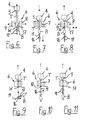
- FIG. 3 shows the automatic cycle starting with the state in which the blow mold 6 is closed.
- the continuously extruded from the extrusion die 5 of the extruder head 4 hose T is indicated by T.
- One of the two blowing mandrels 11 is retracted into the mouth 10 of the Blasformkavmaschine 7.
- Reference numeral 17 stands for the knife inactive in this state.
- the in Fig. 3 shown state is inflated in the Blasformkavtician hose according to the Blasformkavtician.
- the extruder head 4 is raised continuously and the vertical distance to the blow molding tool is continuously increased. This is in Fig.
- the end of the blowing process is in Fig. 5 indicated.
- the extruder head 4 is further removed from the blow molding tool 6 and is further raised.
- the inflated bottle located in the blow mold cavity 7 is vented by the blow mold 6.
- the hanging on the lower mandrel 11 bottle B is removed.
- the blow mold halves 8, 9 of the blow mold 6 are opened, which is in Fig. 6 is indicated.
- the extruder head 4 is still raised.
- the extruder head 4 is driven with the extruded tube piece T and thus connected, finished blown bottle B down in the direction of the blow mold 6.
- the blow mandrel 11 mounted on the mandrel holder 16 is also lowered.
- Figs. 6 and 7 is clearly seen that the extruded tube T is held even when the blow mold 6 is open in an axially defined position. Because the hose is still connected to the finished blown container B, the hose is fixed on the one hand by the extrusion nozzle 6 and on the other hand by the blowing mandrel 11. As a result, oscillation of the tube T is reliably prevented.
- the lowering speed of the extrusion head 4 and the mandrel 11 is advantageously synchronous and at least equal to the extrusion speed of the tube T. By a predetermined difference in the lowering speeds of the continuously extruded tube T can be stretched to the desired extent.
- the axially aligned arrangement of the extruder head 4, the blow molding tool 6 and the mandrel 6 also allows a relatively simple control of the axial movement components.
- the exit velocity of the plastic tube T, the movement of the mandrel 11 and an adjustment of the width of the extrusion die 5 are adjusted individually and coordinated with each other. This allows the implementation of optimized motion sequences, which are tailored to the requirements of the container to be blown B, without having to make changes to the overall concept of the axially aligned method.
- Fig. 8 shows the state in which the mandrel holder 16 has reached its lowest position. Now, the halves of the blow mold 6 are closed again to enclose a new tube section in the mold cavity. Shortly before the blow molding tool 6 is completely closed, the knife 17 is delivered laterally to separate the finished blown bottle B from the protruding from the mouth of Blasformkavmaschine piece of waste. This is in Fig. 8 indicated by a double arrow. The extruder head 4 has meanwhile reversed its direction of movement and is raised again. After severing, the mandrel holder 16 is rotated to align the second mandrel 11 with the mouth of the mandrel cavity.
- Fig. 10 shows the state in which the rotation of the Blasdornhalterung 16 is completed and the mandrel 11 has reached its correct stroke position. Thereafter, it is retracted into the mouth 10 of the Blasformkavtician 7. The subsequent opening of the bottle to be inflated is calibrated. Already during the retraction of the mandrel 11 in the Blasformkavtician 7 can be started with the pre-blowing. The extruder head 4 is thereby raised further. In Fig. 11 the mandrel 11 is finally retracted into the Blasdornkavmaschine the blow mold 6 and the production cycle starts again from the beginning.
- the representation in Fig. 11 corresponds to the representation in Fig. 3 ,
- the invention has been explained using the example of a continuous extrusion blow molding process and a corresponding device with a vertical arrangement of the extruder head, the blow molding tool and the blowing mandrels. It is understood that the arrangement of the device components can also take place in horizontal or any orientation according to the extrusion direction.
- the process according to the invention can also be used in a batch extrusion blow molding process and, accordingly, a discontinuous extrusion blow molding machine can also be produced.
- the key factors in the batch process are equally the provision of hose holding means on either side of the blow mold assembly and the order of extrusion die assembly, blow mold assembly and blow mandrel assembly.
- Essential to the invention is the fact that the extruded tube is held in a controllable position during an entire production cycle and the tube is separated only after the inflation and removal of the container.
- the separation point is located on the side facing away from the extruder head of Blasformwerkmaschinegneanix.
Abstract
Description
Die Erfindung betrifft ein Verfahren zur Herstellung von Hohlkörpern gemäss dem Oberbegriff des Patentanspruchs 1. Die Erfindung betrifft auch eine für diesen Zweck geeignete Vorrichtung.The invention relates to a method for the production of hollow bodies according to the preamble of
Die in der Vergangenheit üblichen Behältnisse aus Weiss- oder Buntblech, aus Glas oder auch aus Keramik werden in zunehmendem Masse von Behältnissen aus Kunststoff abgelöst. Insbesondere für die Verpackung fluider Substanzen, beispielsweise von Getränken, Öl, Reinigungsutensilien, Kosmetika usw., kommen hauptsächlich Kunststoffbehältnisse zum Einsatz. Das geringe Gewicht und die geringeren Kosten spielen sicher eine nicht unerhebliche Rolle bei dieser Substitution. Die Verwendung rezyklierbarer Kunststoffmaterialien und die insgesamt günstigere Gesamtenergiebilanz bei ihrer Herstellung tragen auch dazu bei, die Akzeptanz von Kunststoffbehältnissen, insbesondere von Kunststoffflaschen, beim Konsumenten zu fördern.The usual in the past containers made of white or stained, glass or ceramic are increasingly being replaced by plastic containers. In particular, for the packaging of fluid substances, such as drinks, oil, cleaning utensils, cosmetics, etc., mainly plastic containers are used. The low weight and the lower costs certainly play a significant role in this substitution. The use of recyclable plastic materials and the overall more favorable overall energy balance in their production also contribute to the consumer's acceptance of plastic containers, in particular of plastic bottles.
Die Herstellung von Kunststoffbehältnissen, insbesondere Kunststoffflaschen, beispielsweise aus Polyethylen oder Polypropylen, erfolgt im Extrusionsblasverfahren, insbesondere in einem Schlauchblasverfahren. Dabei wird von einem Extruderkopf ein Kunststoffschlauch extrudiert, in Blasformwerkzeuge eingebracht, über einen Blasdorn durch Überdruck aufgeblasen und durch Kühlung ausgehärtet. Die dafür eingesetzten Extrusionsblasmaschinen besitzen in der Regel wenigstens einen Extruder zur Zuführung des Kunststoffmaterials. Der Ausgang des Extruders ist mit dem Extruderkopf verbunden, an dessen vorzugsweise in der Öffnungsweite regulierbarer Austrittsdüse der ein oder mehrschichtig extrudierte Schlauch austritt. Der extrudierte Schlauch wird an ein Blasformwerkzeug übergeben und innerhalb dessen Kavität mit einem Blasdorn aufgeblasen. Der Kunststoffschlauch kann ein- oder mehrschichtig sein, er kann als Schlauch mit Sichtstreifen, Dekorstreifen oder bezogen auf den Umfang mit mehreren, beispielsweise verschiedenfarbigen, Segmenten extrudiert sein.The production of plastic containers, in particular plastic bottles, for example made of polyethylene or polypropylene, takes place in the extrusion blow molding process, in particular in a tubular blowing process. In this case, extruded from an extruder head, a plastic tube, introduced into blow molds, inflated via a mandrel by overpressure and cured by cooling. The extrusion blow molding machines used for this purpose generally have at least one extruder for feeding the plastic material. The outlet of the extruder is connected to the extruder head, at the preferably in the opening width of the adjustable outlet nozzle, the one or more extruded extruded tube emerges. The extruded tube is transferred to a blow mold and inflated within the cavity with a blow pin. The plastic tube can be single-layered or multi-layered, it can be extruded as a tube with viewing strips, decorative strips or related to the circumference with several, for example, different colored segments.
Die Blasstation mit dem Blasdorn ist üblicherweise seitlich des Extrusionskopfes angeordnet, und das mit dem extrudierten Schlauch beschickte Blasformwerkzeug muss in die Blasstation bewegt werden, wo dann der Blasdorn üblicherweise von oben in die Blasformkavität eingefahren wird. Für den kontinuierlichen Betrieb sind bei einer Art der bekannten Extrusionsblasmaschinen üblicherweise zwei Blasstationen vorgesehen. Jede Blasstation ist mit einem Blasformwerkzeug ausgestattet. Die Blasstationen sind dabei zu beiden Seiten des Extruders, einander gegenüberliegend angeordnet und weisen Blasformtische mit den Blasformwerkzeugen auf, die abwechselnd unter den Extruderkopf bewegt werden, um den extrudierten Schlauch zu empfangen. Dabei wird das Blasformwerkzeug zum Abholen des Schlauches geöffnet. Nach dem Schliessen des Blasformwerkzeugs wird der Schlauch zwischen dem Extrusionskopf und dem Blasformwerkzeug abgetrennt. Danach wird der Blasformtisch wieder in die Blasstation bewegt, wo der Blasdorn in die Kavität des Blasformwerkzeugs eingefahren und der Schlauch gemäss der Blasformkavität aufgeblasen und danach entnommen wird. Bei Mehrfachextrusionsköpfen und Mehrfachblasformwerkzeugen ist jede Blasstation mit einer korrespondierenden Anzahl von Blasdornen ausgestattet, die gemeinsam in die Blasformkavitäten eingefahren werden. Gesamthaft bilden der Extruder mit dem Extruderkopf und die beiden Blasstationen etwa die Form eines T. Dabei stellt der Extruder mit dem Extruderkopf den langen T-Strich dar, während die beiden Blasformtische abwechselnd entlang der kurzen Querstrichhälften unter den Extruderkopf bewegbar sind.The blowing station with the mandrel is usually arranged laterally of the extrusion head, and the blow molding tool fed with the extruded tube must be moved into the blowing station, where then the mandrel is usually retracted from above into the Blasformkavität. For continuous operation, two blowing stations are usually provided in one type of known extrusion blow molding machines. Each blowing station is equipped with a blow molding tool. The blowing stations are arranged on both sides of the extruder, opposite each other and have blow molding with the blow molding tools, which are moved alternately under the extruder head to receive the extruded tube. The blow mold is opened to pick up the hose. After closing the blow molding tool, the tube between the extrusion head and the blow mold is separated. Thereafter, the blow molding is moved back into the blowing station, where the mandrel is inserted into the cavity of the blow mold and the hose is inflated according to the Blasformkavität and then removed. In the case of multiple extrusion heads and multiple blow molding tools, each blowing station is equipped with a corresponding number of blowing mandrels, which are inserted together into the blow molding cavities. Overall, the extruder with the extruder head and the two blowing stations form approximately the shape of a T. In this case, the extruder with the extruder head represents the long T-bar, while the two blow-molding tables are alternately movable along the short cross-half halves under the extruder head.
Extrusionsblasmaschinen der vorstehend beschriebenen Gattung sind erprobt und erlauben bereits hohe Produktionsleistungen. Dennoch besteht der Wunsch nach Verbesserungen, um die erforderlichen Werkzeuginvestitionen, d.h. die Kosten pro Blasformkavität, noch weiter zu senken. Die Notwendigkeit, die Blasformtische mit den Blasformwerkzeugen seitlich zu den Blasstationen zu bewegen, führt zu Totzeiten, die sich aus dem zurückzulegenden Weg und der Bewegungsgeschwindigkeit der Blasformtische ergibt. Wegen der relativ grossen Massen, die beschleunigt und wieder abgebremst werden müssen, kann die Bewegungsgeschwindigkeit nicht beliebig gross gewählt werden. Auch können die seitlich zurückzulegenden Wege aus baulichen Gründen nicht weiter verkürzt werden. Der extrudierte Schlauch muss nach dem Befüllen des Blasformwerkzeugs abgetrennt werden. Dies erfolgt üblicherweise durch ein seitlich zugestelltes Trennmesser. Das aus der Extrusionsdüse ragende, kontinuierlich weiter extrudierte Schlauchteil pendelt nach dem Schneidvorgang hin und her. Insbesondere bei sehr schnellen Taktzyklen kann das Pendeln des Schlauches zu Schwierigkeiten bei der Übergabe des Schlauches an die Blasformkavität führen.Extrusion blow molding machines of the type described above are tried and already allow high production rates. Nevertheless, there is a desire for improvements to further reduce the required tool investment, ie the cost per blow mold cavity. The need to move the blow molding tables laterally with the blow molds to the blow stations results in dead times resulting from the path to be traveled and the speed of movement of the blow molding tables. Because of the relatively large masses, which must be accelerated and decelerated again, the movement speed can not be chosen arbitrarily large. Also, the laterally traversed paths can not be shortened for structural reasons. The extruded tube must be filled after filling of the blow mold are separated. This is usually done by a laterally delivered cutting knife. The projecting from the extrusion die, continuously further extruded tube part oscillates after the cutting process back and forth. Especially with very fast clock cycles, the oscillation of the hose can lead to difficulties in transferring the hose to the blow mold cavity.
Es sind auch Extrusionsblasmaschinen bekannt, bei denen eine Anzahl von Blasformwerkzeugen auf einem rotierenden Rad angeordnet ist. Das Rad steht etwa vertikal und führt die Blasformwerkzeuge etwa tangential an den vom Extrusionskopf kontinuierlich extrudierten Kunststoffschlauch heran. Kurz vor Erreichen des extrudierten Kunststoffschlauchs wird das herangeführte Blasformwerkzeug geöffnet, um den Schlauch abzuholen. Beim Weiterdrehen des Rads wird das Blasformwerkzeug um den eingelegten Schlauch geschlossen und dieser beim Weiterdrehen schliesslich abgeschert. Die Anordnung der Blasformwerkzeuge und die Drehgeschwindigkeit des Rads sind derart gewählt, dass der Schlauch erst abgeschert wird, wenn sich das nachfolgende Blasformwerkzeug um das nächst Schlauchstück geschlossen hat. Der in der Kavität des Blasformwerkzeuges befindliche Schlauch gelangt beim Weiterdrehen des Rades schliesslich in die Blasstation, wo er über einen seitlich in das Formwerkzeug eingeführten Blasdorn gemäss der Blasformkavität aufgeblasen wird. Schliesslich wird der aufgeblasene Hohlkörper durch Öffnen aus dem Blasformwerkzeug ausgegeben. Das am rotierenden Rad angeordnete Blasformwerkzeug wird bei der Weiterbewegung wieder geschlossen und wieder an den Extrusionskopf herangeführt, um einen weiteren extrudierten Schlauch aufzunehmen.Extrusion blow molding machines are also known, in which a number of blow molding tools are arranged on a rotating wheel. The wheel is approximately vertical and leads the blow molding approximately tangentially to the extruded from the extrusion head plastic hose. Shortly before reaching the extruded plastic tube, the introduced blow mold is opened to pick up the hose. As the wheel rotates further, the blow mold is closed around the inserted hose and this is finally sheared off as it rotates further. The arrangement of the blow molding tools and the rotational speed of the wheel are selected such that the hose is sheared off only when the subsequent blow molding tool has closed around the next piece of hose. The tube located in the cavity of the blow molding tool finally passes into the blowing station during further rotation of the wheel, where it is inflated via a blowing mandrel inserted laterally into the molding tool according to the blow molding cavity. Finally, the inflated hollow body is discharged by opening from the blow molding tool. The blow molding tool arranged on the rotating wheel is closed again during the further movement and brought back to the extrusion head in order to receive a further extruded hose.
Nachteilig an den Rad-Blasmaschinen ist der Umstand, dass sie wegen der grossen Zahl von am Rad angeordneten separaten Blasformwerkzeugen einen relativ hohen Investitionsaufwand für die Bereitstellung der Blasformwerkzeuge erfordern. Auch sind die Blasformwerkzeuge in der Regel nicht vollständig identisch. Dies kann von Blasformwerkzeug zu Blasformwerkzeug zu Qualitätsunterschieden bei den hergestellten Hohlkörpern führen. Der Einsatz von Blasformwerkzeugen mit mehreren Blasformkavitäten gestaltet sich relativ schwierig und teuer. Die Blasformwerkzeuge sind nur an fest vorgegebenen Montagepunkten am Rad befestigbar. Diese werden nach der maximal mit der Maschine herstellbaren Höhe des geblasenen Hohlkörpers festgelegt. Die einmal festgelegten Montagepunkte sind nicht mehr veränderbar. Dies ist auch eine Folge der bei diesen Maschinen üblichen mechanischen Steuerungen über Steuerkurven, Kurvenscheiben und dergleichen. Sollen auf der Rad-Blasmaschine Behälter mit kleinerer Bauhöhe geblasen werden, dann weisen die am Umfang des Rads montierten kleineren Blasformwerkzeuge einen grösseren Winkelabstand voneinander auf. Nachdem der Kunststoffschlauch kontinuierlich aus dem Extrusionskopf austritt, führt dies zu grösseren Abfallmengen in den Bereichen zwischen zwei Blasformwerkzeugen. Der extrudierte Kunststoffschlauch wird von dem entlang einer Kreisform unter dem Extrusionskopf vorbeibewegten Blasformwerkzeug übernommen. Dabei wird der seitlichen Zustellbewegung der schliessenden Blasformhälften eine Kreisbogenbewegung überlagert. Zwar wird durch einen möglichst grossen Radius des Rades versucht, diese Kreisbogenbewegung der Blasformhälften bei der Übernahme des Kunststoffschlauchs möglichst klein zu halten; sie kann aber nicht vollständig beseitigt werden. Auch der Umstand dass der Schlauch zwischen zwei aufeinander folgenden Blasformwerkzeugen einerseits vom Extruderkopf und andererseits vom vorlaufenden Blasformwerkzeug gehalten ist, kann an den geometrischen Verhältnissen nichts ändern. Unter ungünstigen Umständen kann es daher insbesondere bei komplexeren Behältergeometrien dazu kommen, dass der Schlauch nicht ideal in die Blaskavität eingelegt und teilweise zwischen aneinander anliegenden Bereichen der schliessenden Blasformhälften eingeklemmt wird. Dies kann zu unerwünschtem Ausschuss führen.A disadvantage of the wheel blow molding machines is the fact that they require a relatively high capital outlay for the provision of the blow molding tools because of the large number of arranged on the wheel separate blow molds. Also, the blow molds are not completely identical in the rule. This can lead from blow mold to blow mold to quality differences in the produced hollow bodies. The use of blow molds with multiple blow mold cavities is relatively difficult and expensive. The blow molds are only attachable to firmly fixed mounting points on the wheel. These are determined by the maximum height of the blown hollow body that can be produced by the machine. Once fixed mounting points are no longer changeable. This is also a consequence of the mechanical controls on control cams, cams and the like customary in these machines. If you want to blow on the wheel blower container with a smaller height, then the mounted on the periphery of the wheel smaller blow molds at a greater angular distance from each other. After the plastic hose emerges continuously from the extrusion head, this leads to larger amounts of waste in the areas between two blow molds. The extruded plastic tube is taken over by the blow mold passing along a circular shape below the extrusion head. In this case, the lateral feed movement of the closing blow mold halves is superimposed on a circular arc movement. Although it is attempted by a maximum radius of the wheel to keep this circular arc movement of the blow mold halves as small as possible when taking over the plastic tube; but it can not be completely eliminated. The fact that the tube is held between two consecutive blow molds on the one hand by the extruder head and the other by the leading blow mold, can not change the geometric conditions. Under unfavorable circumstances, it may therefore happen, especially in the case of more complex container geometries, that the tube is not inserted ideally into the blow cavity and is partially clamped between abutting areas of the closing blow mold halves. This can lead to unwanted rejects.
Aus der
Aus der
Aus der
Aufgabe der vorliegenden Erfindung ist es daher, die Nachteile der Verfahren und Vorrichtungen des Stands der Technik zu vermeiden. Es sollen ein Blasformverfahren und eine Extrusionsblasmaschine geschaffen werden, welche eine zuverlässige Verarbeitung verschiedener Kunststoffrohprodukte erlaubt. Bezüglich der Gestaltung der Behältergeometrien sollen möglichst viele Freiräume bestehen, und es sollen auch Behälter mit sehr komplexer Geometrie mit sehr engen Spezifikationen herstellbar sein. Bei der Herstellung kritischer Behältergeometrien oder dünnwandiger Behälter soll eine möglichst hohe Produktionssicherheit gewährleistet sein. Das Verfahren und die Vorrichtung zum Extrusionsblasen von Hohlkörpern sollen für die Herstellung grosser und kleiner Geometrien kompatibel sein. Dabei sollen unnötige Kunststoffabfälle weitgehend vermieden werden. Das Verfahren und die Vorrichtung sollen dahingehend modifiziert werden, dass unabhängig von der Anzahl der Kavitäten je Blasformwerkzeug weitgehend identische Behältereigenschaften und Qualitätsparameter erreicht werden können. Die im Versuch ermittelten Einstelldaten sollen weitgehend unverändert auf Produktionsanlagen übertragbar sein. Der Platzbedarf gegenüber bestehenden Maschinen soll nicht grösser sein, ja es soll sogar ermöglicht werden, diesen zu verringern. Totzeiten, wie sie bei den bekannten Maschinen bei der seitlichen Verschiebung der Blasformwerkzeuge in die Blasstationen auftreten, sollen verringert werden.The object of the present invention is therefore to avoid the disadvantages of the methods and devices of the prior art. A blow-molding process and an extrusion blow-molding machine are to be created which permit reliable processing of various plastic raw products. With regard to the design of the container geometries should be as many open spaces, and it should also be able to produce containers with very complex geometry with very tight specifications. When producing critical container geometries or thin-walled containers, the highest possible production reliability should be ensured. The method and the device for extrusion blow molding of hollow bodies should be compatible for the production of large and small geometries. In doing so, unnecessary plastic waste should be largely avoided. The method and the device should be modified to the effect that, regardless of the number of cavities per blow mold largely identical container properties and quality parameters can be achieved. The adjustment data determined in the experiment should be largely transferable to production plants without any changes. The space requirement compared to existing machines should not be greater, yes it should even be possible to reduce this. Dead times, as they occur in the known machines in the lateral displacement of the blow molds in the blow molding stations, should be reduced.
Die Lösung dieser Aufgaben besteht in einem Verfahren zum Herstellung von Hohlkörpern, welches die im kennzeichnenden Abschnitt des Patentanspruchs 1 angeführten Merkmale aufweist. Eine erfindungsgemässe Vorrichtung weist die im kennzeichnenden Abschnitt des unabhängigen Vorrichtungsanspruchs angeführten Merkmale auf. Weiterbildungen und/oder vorteilhafte Ausführungsvarianten der Erfindung sind Gegenstand der abhängigen Verfahrens- bzw. Vorrichtungsansprüche.The solution to these problems consists in a method for producing hollow bodies, which has the features mentioned in the characterizing portion of
Bei dem Verfahren zur Herstellung von Hohlkörpern, insbesondere von Kunststoffflaschen, wird von einem Extruderkopf in einem vorgebbaren Takt ein Abschnitt eines Kunststoffschlauchs in eine Kavität eines Blasformwerkzeugs eingebracht. Innerhalb des Blasformwerkzeuges wird der Kunststoffschlauch über einen Blasdorn durch Überdruck gemäss der Blasformkavität aufgeblasen. Der fertig geblasene Hohlkörper wird schliesslich entformt. Der Kunststoffschlauch wird während eines gesamten Extrusions- und Blaszyklusses an gegenüberliegenden Seiten der Blasformwerkzeuganordnung kontinuierlich gehalten.In the method for producing hollow bodies, in particular plastic bottles, a section of a plastic tube is introduced into a cavity of a blow molding tool by an extruder head in a predeterminable cycle. Within the blow molding tool, the plastic tube is inflated via a mandrel by overpressure according to the Blasformkavität. The finished blown hollow body is finally removed from the mold. The plastic tubing is continuously held on opposite sides of the blow molder assembly throughout an entire extrusion and blowing cycle.
Bei dem erfindungsgemässen Verfahren ist der Kunststoffschlauch während eines gesamten Herstellungszyklusses, d.h. während eines gesamten Extrusions- und Blaszyklusses, an gegenüberliegenden Seiten der Blasformwerkzeuganordnung kontinuierlich gehalten. Dadurch ist der Kunststoffschlauch permanent geführt und Fehllagen können vermieden werden. Dadurch ist die Voraussetzung geschaffen, einen von einer Extrusionsdüse extrudierten Schlauch immer in dieselbe Blasformkavität einzubringen. Alle mit einer Extrusionsdüse-Blasformkavität-Anordnung hergestellten Hohlkörper erfahren auf diese Weise dieselben Einstell- und Werkzeugparameter. Qualitätsunterschiede infolge unterschiedlich grosser Toleranzen der Blasformkavitäten bei Anordnungen mit mehreren verschiedenen Blasformwerkzeugen entfallen. Totzeiten, die durch eine seitliche Verschiebung der Blasformwerkzeuganordnung gegenüber dem Extruderkopf erfolgen, entfallen, da die Blasformwerkzeuganordnung im Wesentlichen nur auf die Transportrichtung des Kunststoffschlauchs ausgerichtet ist. Das Aufblasen des in der Blasformkavität befindlichen Kunststoffschlauchs erfolgt unmittelbar nach der Beschickung der Blasformkavität mit dem extrudierten Kunststoffschlauch. Der Kunststoffschlauch ist während des gesamten Extrusions- und Blaszyklusses in einer definierten Lage gehalten und kann nicht mehr um seine Achse pendeln. Der Extruderkopf und die Blasformwerkzeuganordnung verbleiben während des gesamten Extrusions- und Blasvorgangs in einer vorgebbaren und justierbaren, geometrischen Lagebeziehung, und der Kunststoffschlauch kann immer optimal übernommen werden. Dadurch wird auch bei komplizierteren Geometrien der Blasformkavität die Gefahr eines unbeabsichtigten Einklemmens des Kunststoffschlauchs verringert. Die erfindungsgemässe Verfahrensführung erlaubt es, bei Bedarf die Lage des extrudierten Kunststoffschlauchs in Bezug auf die Blasformkavität gezielt zu verändern, um speziellen geometrischen Anforderungen Rechnung zu tragen.In the method according to the invention, the plastic tube is continuous on opposite sides of the blow molding tool assembly during an entire production cycle, ie during an entire extrusion and blowing cycle held. As a result, the plastic tube is permanently guided and misplaced situations can be avoided. As a result, the condition is created to always introduce a extruded from an extrusion die hose in the same Blasformkavität. All of the hollow bodies produced with an extrusion die-blow mold cavity arrangement thus experience the same setting and tool parameters. Differences in quality due to different sized tolerances of Blasformkavitäten omitted in arrangements with several different blow molds. Dead times, which take place by a lateral displacement of the blow molding tool arrangement with respect to the extruder head, are dispensed with, since the blow mold arrangement is oriented substantially only in the transport direction of the plastic tube. The inflating of the plastic hose located in the blow mold cavity takes place immediately after the charging of the blow mold cavity with the extruded plastic hose. The plastic tube is held in a defined position during the entire extrusion and Blaszyklusses and can no longer oscillate about its axis. The extruder head and the blow molding tool remain in a predeterminable and adjustable, geometric positional relationship throughout the extrusion and blowing process, and the plastic tube can always be optimally adopted. As a result, the risk of unintentional trapping of the plastic tube is reduced even with more complicated geometries of Blasformkavität. The method according to the invention allows the position of the extruded plastic tube with respect to the blow mold cavity to be changed as required in order to take into account special geometrical requirements.
In einer vorteilhaften Variante des erfindungsgemässen Verfahrens wird der Kunststoffschlauch erst nach dem vollständigen Aufblasen des Hohlkörpers abgetrennt. Das Abtrennen kann durch kontrolliertes Abquetschen oder auch durch Abscheren erfolgen. Vorzugsweise wird dazu ein Trennmesser oder dergleichen eingesetzt. Diese Verfahrensvariante unterscheidet sich sowohl von dem Blasverfahren mit den bekannten Rad-Blasmaschinen, bei denen der Schlauch nach der Übernahme durch das Blasformwerkzeug beim Weiterdrehen des Rades im wesentlichen unkontrolliert abgeschert wird, als auch von den kontinuierlichen und diskontinuierlichen Blasverfahren mit bekannten Extrusionsblasmaschinen, bei denen der Kunststoffschlauch vor dem eigentlichen Blasvorgang kontrolliert geschnitten wird. Zwar bedingt die erfindungsgemässe Verfahrensführung, dass der Blasdorn für eine gewisse Zeit mit der Bewegung des Extruderkopfes und/oder der Extrusions- oder Übergabegeschwindigkeit des Kunststoffschlauchs an die Blasformwerkzeuganordnung synchronisiert werden muss. Durch diese einfache Massnahme ist aber sichergestellt, dass der Schlauch in jeder Phase des Herstellungszyklusses kontrolliert gehalten ist.In an advantageous variant of the method according to the invention, the plastic tube is separated only after complete inflation of the hollow body. The separation can be done by controlled squeezing or by shearing. Preferably, a separating knife or the like is used for this purpose. This variant of the method differs both from the blow molding process with the known wheel blow molding machines, in which the tube is sheared after uncontrolled after taking over the blow mold on further rotation of the wheel, as well as the continuous and discontinuous blow molding with known extrusion blow molding machines, in which Plastic hose in front of the actual blow process is controlled cut. It is true that the method according to the invention requires that the mandrel be synchronized for a certain time with the movement of the extruder head and / or the extrusion or transfer speed of the plastic tube to the blow molding tool arrangement. However, this simple measure ensures that the hose is kept controlled at every stage of the production cycle.
Die Trennung des Kunststoffschlauchs erfolgt mit Vorteil an der dem Extruderkopf abgewandten Seite der Blasformwerkzeuganordnung. Dadurch ist vor dem Abtrennen die Führung des Schlauchs über den auf dem Blasdorn befindlichen fertig geblasenen Hohlkörper und den Extruderkopf sichergestellt. Durch eine Anordnung der Trennstelle in unmittelbarer Nachbarschaft zur Mündung der Blasformkavität kann der Schlauchmaterialabfall unabhängig von der Höhe der Blasformkavität immer möglichst klein gehalten werden.The separation of the plastic tube is advantageously carried out on the side facing away from the extruder head of Blasformwerkzeuganordnung. As a result, before the separation of the leadership of the hose on the blow spool located on the finished blown hollow body and the extruder head ensured. By arranging the separation point in the immediate vicinity of the mouth of Blasformkavität the hose material waste can always be kept as small as possible regardless of the height of Blasformkavität.
Bezogen auf die Bewegungsrichtung des Kunststoffschlauchs ist die Blasformwerkzeugeinrichtung zwischen dem Extruderkopf und dem Blasdorn angeordnet. Der Blasdorn wird durch eine Mündung der Blasformkavität eingefahren, die an der von der Extrusionsdüse abgewandten Seite der Blasformwerkzeuganordnung angeordnet ist. Der Ausgang der Extrusionsdüse und die axiale Erstreckung des Blasdorns sind dabei derart angeordnet, dass sie im Wesentlichen axial fluchten.Based on the direction of movement of the plastic tube, the Blasformwerkzeuginrichtung is disposed between the extruder head and the mandrel. The mandrel is retracted through an opening of the Blasformkavität, which is arranged on the side facing away from the extrusion nozzle side of the Blasformwerkzeuganordnung. The outlet of the extrusion nozzle and the axial extension of the blowing mandrel are arranged such that they are aligned substantially axially.
In einer Variante der Erfindung sind zur Verringerung der Totzeiten für jede Blasformkavität zwei oder mehr Blasdorne vorgesehen. Die Blasdorne können beispielsweise nebeneinander angeordnet sein und abwechselnd auf die Öffnungen der Blasformkavitäten zugestellt werden. In einer alternativen Ausführungsvariante sind mehrere Blasdorne derart an einer zentralen Blasdornhalterung befestigt, dass sie durch Rotation der Blasdornhalterung nacheinander zum Einsatz gelangen. Beispielsweise kann die Blasdornhalterung zwei Blasdorne tragen, die um 180° versetzt einander gegenüberliegen. Bei einer derartigen Ausführungsvariante wird nach dem Aufblasen des Schlauchs und dem Öffnen der Blasformwerkzeuganordnung die Blasdornhalterung um 180° gedreht. Der zweite Blasdorn ist somit bereits für das Aufblasen eines weiteren Schlauchabschnitts bereit, während der Hohlkörper am ersten Blasdorn noch auf seine Entnahme wartet. Es versteht sich, dass auch drehbare Blasdornhalterungen mit 3, 4 oder mehreren Blasdornen vorgesehen sein können. Der Winkel, um den die Blasdornhalterung jeweils weitergedreht werden muss, ergibt sich dann aus der Teilung von 360° durch die Anzahl Blasdome.In a variant of the invention, two or more blowing mandrels are provided for reducing the dead times for each blow mold cavity. The blowing mandrels can for example be arranged side by side and be delivered alternately to the openings of the blow mold cavities. In an alternative embodiment, a plurality of blowing mandrels are attached to a central Blasdornhalterung such that they are used by rotation of the Blasdornhalterung successively used. For example, the Blasdornhalterung can carry two mandrels, offset by 180 ° to each other. In such an embodiment variant, the blow mandrel holder is rotated by 180 ° after inflation of the tube and the opening of the blow mold assembly. The second mandrel is thus already ready for the inflation of another hose section, while the hollow body is still waiting for its removal at the first mandrel. It is understood that rotatable Blasdornhalterungen with 3, 4 or more Blasdornen can be provided. The angle by which the Blasdornhalterung must be further rotated, then results from the division of 360 ° by the number Blasdome.
Die Anordnung an der der Extrusionsdüse abgewandten Seite der Blasformwerkzeuganordnung bietet auch die Möglichkeit, jeden Blasdorn mit einer Kalibriereinrichtung zu versehen, mit der bereits während des Blasvorgangs die Öffnung des geblasenen Hohlkörpers kalibriert wird. Dadurch entfällt eine separate Nachbearbeitungsstation, in der dieser Vorgang nachgeholt werden muss.The arrangement on the side of the blow molding tool arrangement facing away from the extrusion nozzle also offers the possibility of providing each blowing mandrel with a calibrating device with which the opening of the blown hollow body is already calibrated during the blowing process. This eliminates a separate post-processing station, in which this process must be made up.
Bei einem kontinuierlichen Extrusionsblasverfahren wird der Kunststoffschlauch kontinuierlich aus der Extrusionsdüse des Extruderkopfes extrudiert. Nach der Übergabe des extrudierten Kunststoffschlauches an die Blasformkavität und während des gesamten Blasvorgangs wird der relative Abstand des Extruderkopfes von der Blasformwerkzeuganordnung vergrössert, damit er bei der weiteren Extrusion nicht gegen die Oberfläche der Blasformwerkzeuganordnung anläuft und der Schlauch in einer kontrollierten Ausrichtung gehalten werden kann. Dadurch wird dem Umstand Rechnung getragen, dass der Kunststoffschlauch kontinuierlich aus der Extrusionsdüse extrudiert wird, während der Aufblasvorgang in der Formkavität der Blasformwerkzeuganordnung ein diskontinuierlicher Prozess ist.In a continuous extrusion blown process, the plastic tube is extruded continuously from the extrusion die of the extruder head. After transfer of the extruded plastic tube to the blow mold cavity and throughout the blowing process, the relative distance of the extruder head from the blow molder assembly is increased to prevent it from starting against the surface of the blow molder assembly during further extrusion and to maintain the tube in a controlled orientation. This accounts for the fact that the plastic tubing is continuously extruded from the extrusion die while the inflation process in the mold cavity of the blow mold assembly is a discontinuous process.
Die relative Abstandsveränderung zwischen dem Extruderkopf und der Blasformwerkzeuganordnung erfolgt wenigstens mit einer Geschwindigkeit, die der Austrittsgeschwindigkeit des Kunststoffschlauchs aus der Extrusionsdüse entspricht. Dadurch ist sichergestellt, dass der extrudierte Schlauch nicht auf die Oberfläche der Blasformwerkzeuganordnung aufläuft. Bei der Wahl einer grösseren Geschwindigkeit der Abstandsveränderung als der Extrusionsgeschwindigkeit wird der bereichsweise in der Blasformwerkzeuganordnung eingeklemmte Kunststoffschlauch gleichsam aus dem Düsenwerkzeug gezogen. Dadurch kann beispielsweise die Wandstärke des extrudierten Kunststoffschlauchs gezielt verändert werden. Es kann somit auch mit einem relativ grossen Düsenspalt ein dünnwandiger Schlauch erzeugt werden. Dies hat zum einen den Vorteil, dass trotz hohem Durchsatz der Druck im Extruderkopf vergleichsweise gering gehalten werden kann, und zum anderen die Dissipation und somit die Temperaturerhöhung im Schlauch geringer wird. Ein weiterer Vorteil besteht darin, dass auch bei der Verarbeitung von stark quellenden Materialien ein dünnwandiger Schlauch erzeugt werden kann, da aufgrund des grösseren Düsenspaltes und der damit verbundenen geringeren Scherung die Gefahr eines Schmelzebruchs verringert ist. Es kann auch vorgesehen sein, die Relativgeschwindigkeiten zwischen dem Extruderkopf und dem Blasdorn bzw. der Blasform während des kontinuierlichen Schlauchaustritts laufend gemäss einem Dehnungsprogramm zu verändern, um die Schlauchwandstärke im gewünschten Ausmass zu beeinflussen.The relative change in distance between the extruder head and the blow mold arrangement takes place at least at a speed which corresponds to the exit speed of the plastic tube from the extrusion die. Thereby it is ensured that the extruded tube does not run on the surface of the blow mold arrangement. When choosing a greater speed of the change in distance than the extrusion speed of the partially clamped in the Blasformwerkzeuganordnung plastic tube is drawn as it were from the nozzle tool. As a result, for example, the wall thickness of the extruded plastic tube can be selectively changed. It can thus be produced with a relatively large nozzle gap a thin-walled hose. This has the advantage that, despite high throughput, the pressure in the extruder head can be kept relatively low, and on the other hand, the dissipation and thus the increase in temperature in the hose is lower. Another advantage is that a thin-walled hose can be produced even when processing highly swelling materials, since the risk of melt fracture is reduced due to the larger nozzle gap and the associated lower shear. It can also be provided to continuously change the relative speeds between the extruder head and the mandrel or the blow mold during the continuous hose outlet according to a strain program in order to influence the hose wall thickness to the desired extent.
Zur Erzielung der Abstandsveränderung zwischen dem Extruderkopf und der Blasformwerkzeuganordnung besteht die Möglichkeit, den Extruderkopf oder die Blasformwerkzeuganordnung weg zu bewegen oder eine Kombination beider Bewegungen durchzuführen. Die Verstellung nur eines der beiden Geräteteile vereinfacht den konstruktiven Aufbau und die Steuerung der Bewegungsabläufe. Aus konstruktiven Überlegungen erweist es sich dabei als zweckmässig, wenn die Abstandsveränderung nur durch ein Wegbewegen des Extruderkopfes gegenüber der bezüglich ihrer Lage stationären Blasformwerkzeuganordnung erfolgt. Einerseits besteht im Bereich des Extruderkopfes mehr Raum für die Anbringung der Hubmittel. Andererseits ist es von Vorteil für die Zustellung des Blasdorns, wenn die Blasformwerkzeuganordnung während des gesamten Blaszyklusses ihre Position im wesentlichen unverändert beibehält. Die Blasformwerkzeuganordnung muss zur Aufnahme des Schlauchabschnitts in der Blasformkavität nur eine Öffnungs- und Schliessbewegung ausführen. Diese Vorgänge sind einfacher und exakter steuerbar, wenn die Blasformwerkzeuganordnung keine weitere Bewegung ausführt.In order to achieve the change in distance between the extruder head and the blow molding tool assembly, it is possible to move the extruder head or the blow mold assembly away or perform a combination of both movements. The adjustment of only one of the two parts simplifies the structural design and the control of the motion sequences. For constructive considerations, it proves to be expedient if the change in distance takes place only by moving the extruder head away from the blow molding tool arrangement which is stationary relative to its position. On the one hand, there is more space in the area of the extruder head for attaching the lifting means. On the other hand, it is advantageous for the delivery of the mandrel when the blow molding tool assembly maintains its position substantially unchanged during the entire Blaszyklusses. The Blasformwerkzeuganordnung must perform only an opening and closing movement for receiving the tube portion in the Blasformkavität. These processes are easier and more precisely controllable when the blow molding tool assembly does not make any further movement.
Bei einem diskontinuierlichen Blasverfahren wird der Kunststoffschlauch diskontinuierlich aus der Extrusionsdüse eines als Staukopf ausgebildeten Extruderkopfes in die Blasformkavität ausgestossen. Während des Ausstossens des Kunststoffschlauchs wird der Abstand des Blasdorns vom Staukopf vergrössert. Der Aufbau der Extrusionsblasmaschine für das diskontinuierliche Verfahren entspricht weitgehend demjenigen der kontinuierlichen Maschinen. Zum Unterschied von den bekannten diskontinuierlichen Verfahren wird jedoch der Schlauch während des Herstellungsprozesses permanent gehalten und kontrolliert geführt. Dadurch wird ein unkontrolliertes Pendeln des Schlauches verhindert. Ausserdem kann das Halten des Schlauches bei Bedarf auch für eine kontrollierte Dehnung oder Lageveränderung desselben eingesetzt werden.In a batch blow process, the plastic tube is discontinuously ejected from the extrusion die of an extruder head designed as a stuffer head into the blow mold cavity. During the ejection of the plastic tube, the distance of the mandrel is increased by the jam head. The structure of the extrusion blow molding machine for the batch process largely corresponds to that of the continuous machines. In contrast to the known batch processes, however, the hose is permanently held during the production process and guided in a controlled manner. This prevents uncontrolled oscillation of the hose. In addition, the holding of the hose can also be used for a controlled stretching or change in position if necessary.
Auch bei dem diskontinuierlichen Verfahren muss verhindert werden, dass der Schlauch auf die Oberfläche der Blasformwerkzeuganordnung aufläuft. Dazu wird die Geschwindigkeit der Abstandsveränderung des Blasdorns vom Staukopf gleich oder grösser eingestellt als die Ausstossgeschwindigkeit des Kunststoffschlauchs aus der Extrusionsdüse.Even with the discontinuous method must be prevented that the hose runs on the surface of the blow mold assembly. For this purpose, the speed of the change in distance of the mandrel is set by the accumulation head equal to or greater than the ejection speed of the plastic tube from the extrusion die.
Das erfindungsgemässe Verfahren, bei dem der Kunststoffschlauch während eines gesamten Herstellungszyklusses kontrolliert geführt ist, erlaubt eine Verfahrensführung mit beliebiger Bewegungsrichtung des Kunststoffschlauchs. Während die bekannten Verfahren im Wesentlichen auf eine vertikale Extrusionsrichtung des Kunststoffschlauchs beschränkt sind, ermöglicht die Führung des Schlauchs auch eine schräge, ja sogar eine horizontale Ausrichtung. Aus Gründen der Kompatibilität mit bestehenden Maschinen wird jedoch eine axiale Ausrichtung bevorzugt. Eine axial ausgerichtete Anordnung des Extruderkopfes, der Blasformwerkzeuganordnung und des Blasdorns erlaubt eine relativ einfache Steuerung der axialen Bewegungskomponenten.The method according to the invention, in which the plastic tube is guided in a controlled manner during an entire production cycle, permits a process control with any direction of movement of the plastic tube. While the known methods are essentially limited to a vertical extrusion direction of the plastic tube, the guidance of the tube also allows an oblique, even a horizontal alignment. However, for compatibility with existing machines, axial alignment is preferred. An axially aligned arrangement of the extruder head, the blow mold assembly and the blow mandrel allows a relatively simple control of the axial movement components.
Mit Vorteil sind dabei die Austrittsgeschwindigkeit des Kunststoffschlauchs, die Extruderkopfbewegung, eine Verstellbewegung der Weite der Extrusionsdüse, die Blasdombewegung und die Öffnungs- bzw. Schliessbewegung der Blasformwerkzeuganordnung individuell und aufeinander abgestimmt einstellbar. Dies erlaubt die Umsetzung optimierter Bewegungsabläufe, die auf die Erfordernisse des zu blasenden Behältnisses abgestimmt sind, ohne dadurch am Gesamtkonzept des erfindungsgemässen Verfahrens Änderungen vornehmen zu müssen. Beispielsweise kann vorgesehen sein, dass der Kunststoffschlauch während eines Herstellungszyklusses schräg gestellt wird, um spezielle Geometrien von Blasformkavitäten optimal bedienen zu können und spezielle Behältergeometrien herzustellen.Advantageously, the exit speed of the plastic tube, the extruder head movement, an adjustment of the width of the extrusion die, the Blasdombewegung and the opening or closing movement of Blasformwerkzeuganordnung individually and coordinated adjusted. This allows the implementation of optimized movements, which are tailored to the requirements of the container to be blown, without having to make changes to the overall concept of the inventive method. For example, it can be provided that the plastic tube is inclined during a manufacturing cycle in order to be able to optimally serve special geometries of blow mold cavities and to produce special container geometries.
In einer zweckmässigen Ausführungsvariante der Erfindung umfasst die Blasformwerkzeuganordnung wenigstens zwei voneinander trennbare Formteile, die zum Öffnen und Schliessen des Blasformwerkzeugs im Wesentlichen senkrecht zur Extrusionsrichtung aus einer Offen-Endstellung in eine Geschlossen-Endstellung und umgekehrt bewegt werden. Beispielsweise kann es sich um ein Blasformwerkzeug handeln, welches neben den Formteilen zum Aufbau des Behälterkörpers auch ein abhebbares Bodenteil aufweist. Bei einer in ihrer Lage fixierten Blasformwerkzeuganordnung können die Stellmittel für den Öffnungs- und Schliessvorgang gleichfalls ortsfest angeordnet sein. Der Verzicht auf eine zusätzliche Bewegungskomponente vereinfacht den mechanischen Aufbau und trägt auch dazu bei, den Steuerungsaufwand für die kontrollierten Bewegungen der Formteile zu reduzieren.In an expedient embodiment of the invention, the blow molding tool assembly comprises at least two separable moldings, which are moved to open and close the blow mold substantially perpendicular to the extrusion direction from an open end position to a closed end position and vice versa. For example, it may be a blow molding tool which, in addition to the molded parts for constructing the container body, also has a lift-off bottom part. In the case of a blow molding tool arrangement fixed in its position, the actuating means for the opening and closing operation can likewise be arranged in a stationary manner. The absence of an additional movement component simplifies the mechanical structure and also helps to reduce the control effort for the controlled movements of the molded parts.
Die Vorteile des Verfahrens wurden am Beispiel eines Extruderkopfes mit nur einer Extrusionsdüse und einer Blasformwerkzeuganordnung mit nur einer Blasformkavität erläutert. Die Blasformwerkzeuganordnung kann beispielsweise auch ein Einzelwerkzeug oder eine Anordnung von Werkzeugen mit einer oder mehreren Blasformkavitäten sein, die miteinander gekoppelt sind. In einer zweckmässigen Verfahrensvariante werden ein Extruderkopf mit einem Mehrfachextrusionsdüsenwerkzeug und eine Blasformwerkzeuganordnung eingesetzt, welche mit einer korrespondierenden Anzahl von Blasformkavitäten ausgestattet ist. Ausserdem ist eine Anzahl von Blasdornen vorgesehen, die das ein- oder mehrfache der Zahl Blasformkavitäten beträgt und die zum Aufblasen der Kunststoffschläuche in die Mündungen der Blasformkavitäten eingefahren werden können. Auf diese Weise ist in einem Blaszyklus bei gleichbleibenden Maschinen- und Werkzeugparametern eine grössere Anzahl von Hohlkörpern, beispielsweise Kunststoffflaschen, erzeugbar. Dadurch wird der Durchsatz erhöht, und die Rentabilität einer Mehrfachblasformwerkzeuganordnung kann noch weiter verbessert werden.The advantages of the method were explained using the example of an extruder head with only one extrusion die and a blow mold assembly with only one blow mold cavity. For example, the blow mold assembly may also be a single tool or an assembly of tools having one or more blow mold cavities coupled together. In an expedient variant of the method, an extruder head with a multiple extrusion die tool and a blow molding tool arrangement are used which have a corresponding number is equipped by blow mold cavities. In addition, a number of Blasdornen is provided, which is one or more times the number Blasformkavitäten and can be retracted for inflating the plastic tubes in the mouths of Blasformkavitäten. In this way, a larger number of hollow bodies, for example plastic bottles, can be produced in a blowing cycle with constant machine and tool parameters. Thereby, the throughput is increased, and the profitability of a multiple blow molding tool assembly can be further improved.
Eine zur Durchführung des erfindungsgemässen Verfahrens geeignete Extrusionsblasvorrichtung zur Herstellung von Hohlkörpern, insbesondere von Kunststoffflaschen, weist einen in einem Geräterahmen angeordneten Extruderkopf mit einer Extrusionsdüse, eine Blasformwerkzeuganordnung mit wenigstens einer Blasformkavität, wenigstens einen Blasdorn und wenigstens eine Trenneinrichtung auf. Es sind an gegenüberliegenden Seiten der Blasformwerkzeuganordnung Halteeinrichtungen für den Kunststoffschlauch vorgesehen. Die Trenneinrichtung ist an der dem Extruderkopf abgewandten Seite der Blasformwerkzeuganordnung vorgesehen.An extrusion blow apparatus suitable for carrying out the method according to the invention for producing hollow bodies, in particular plastic bottles, has an extruder head with an extrusion die arranged in a tool frame, a blow mold arrangement with at least one blow mold cavity, at least one blow mandrel and at least one separator. There are provided on opposite sides of the Blasformwerkzeuganordnung holding means for the plastic tube. The separating device is provided on the side of the blow molding tool arrangement facing away from the extruder head.
Durch das Vorsehen von Halteeinrichtungen für den Kunststoffschlauch zu beiden Seiten der Blaswerkzeuganordnung ist der Schlauch während des gesamten Herstellungszyklusses eines Behälters kontinuierlich gehalten. Dadurch sind die Voraussetzungen für die Verwendung einer einzigen Blasformkavität je Extrusionsdüse geschaffen. Totzeiten durch seitliche Bewegungen der Blasformwerkzeugeinrichtung werden vermieden. Durch die permanente Führung des Kunststoffschlauchs werden Fehllagen vermieden. Falls es erforderlich erscheint, kann die Lage des Schlauchs aber auch gezielt gegenüber der Extrusionsrichtung verändert werden. Auf diese Weise kann beispielsweise auch den Anforderungen von komplizierteren Behältergeometrien Rechnung getragen werden. Alle mit einer Extrusionsdüsen-Blasformwerkzeuganordung hergestellten Hohlkörper erfahren dieselben Einstell- und Werkzeugparameter. Qualitätsunterschiede infolge unterschiedlich grosser Werkzeugtoleranzen bei mehreren verschiedenen Blasformwerkzeugen entfallen. Totzeiten, die durch eine seitliche Verschiebung der Blasformwerkzeuganordnung gegenüber dem Extruderkopf auftreten, können vermieden werden, da die Blasformwerkzeuganordnung im Wesentlichen nur auf die Transportrichtung des Kunststoffschlauchs ausgerichtet ist. Das Aufblasen des in der Blasformkavität befindlichen Kunststoffschlauchs erfolgt unmittelbar nach der Beschickung der Blasformkavität mit dem extrudierten Kunststoffschlauch. Der Kunststoffschlauch ist während des gesamten Herstellungszyklusses in einer definierten Lage fixiert und kann nicht mehr um seine Achse pendeln. Der Extruderkopf und die Blasformwerkzeuganordnung verbleiben während des gesamten Extrusions- und Blasvorgangs im Wesentlichen in einer vorgebbaren und justierbaren, geometrischen Lagebeziehung, und der Kunststoffschlauch kann immer optimal übernommen werden. Dadurch wird auch bei komplizierteren Geometrien der Blasformkavität die Gefahr eines unbeabsichtigten Einklemmens des Kunststoffschlauchs verringert.By providing retention means for the plastic tubing on both sides of the blow mold assembly, the tubing is continuously held throughout the entire production cycle of a container. This creates the conditions for the use of a single Blasformkavität per extrusion die. Dead times due to lateral movements of the blow molding tool device are avoided. The permanent guidance of the plastic tube prevents misplacements. If necessary, the position of the hose can also be changed in a targeted manner with respect to the extrusion direction. In this way, for example, the requirements of more complicated container geometries are taken into account. All of the hollow bodies made with an extrusion die blow mold assembly experience the same setting and tooling parameters. Differences in quality due to different sized tool tolerances in several different blow molds omitted. Dead times caused by a lateral shift the blow molding tool arrangement relative to the extruder head can be avoided, since the blow mold arrangement is oriented substantially only to the transport direction of the plastic tube. The inflating of the plastic hose located in the blow mold cavity takes place immediately after the charging of the blow mold cavity with the extruded plastic hose. The plastic tube is fixed in a defined position during the entire production cycle and can no longer oscillate about its axis. The extruder head and the blow mold assembly remain substantially in a predeterminable and adjustable geometrical positional relationship throughout the extrusion and blowing process, and the plastic tubing can always be optimally handled. As a result, the risk of unintentional trapping of the plastic tube is reduced even with more complicated geometries of Blasformkavität.
Die Haltevorrichtungen für den Schlauch werden einerseits durch den Blasdorn und andererseits durch den Extruderkopf gebildet. Durch den Einsatz bereits vorhandener Maschinenkomponenten für die Haltefunktion können der Aufbau einfach und die Bauweise kompakt gehalten werden.The holding devices for the hose are formed on the one hand by the mandrel and on the other hand by the extruder head. By using already existing machine components for the holding function, the structure can be kept simple and the construction compact.
Bei einer auch aus Platzgründen zweckmässigen Anordnung ist die Blasformwerkzeuganordnung zwischen dem Extruderkopf und dem Blasdorn angeordnet. Die Blasformkavität weist eine Mündung an der der Extrusionsdüse abgewandten Seite der Blasformwerkzeuganordnung auf, in welche der Blasdorn in die Blasformkavität einfahrbar ist. Bei dieser Anordnung sind die Verstell- und Zustellbewegungen der Gerätekomponenten im wesentlichen auf Bewegungen entlang der Bewegungsrichtung des Kunststoffschlauchs bzw. im Wesentlichen senkrecht beschränkt. Dies führt zu geringeren mechanischen Beanspruchungen und verringert die im Betrieb auftretenden Vibrationen und Erschütterungen.In an expedient also for reasons of space arrangement, the blow molding tool assembly between the extruder head and the mandrel is arranged. The blow mold cavity has an orifice on the side of the blow molding tool arrangement facing away from the extrusion nozzle, into which the blowing mandrel can be inserted into the blow mold cavity. In this arrangement, the adjusting and advancing movements of the device components are essentially limited to movements along the direction of movement of the plastic tube or substantially perpendicular. This leads to lower mechanical stresses and reduces the vibrations and vibrations that occur during operation.
Eine Ausführungsform der Erfindung sieht für die Blasformkavität zwei oder mehrere Blasdorne vor, die abwechselnd zustellbar sind. Dabei können die Blasdorne beispielsweise nebeneinander angeordnet sein und abwechselnd in die korrekte Position bewegt werden. Die Transportwege der Blasdorne sind sehr kurz. Dadurch können die Totzeiten für die Zustellung des Blasdorns kurz gehalten werden. Eine alternative Variante sieht vor, dass die Blasdorne an einer zentralen Blasdornhalterung montiert sind, und durch Rotation der Blasdornhalterung nacheinander zum Einsatz bringbar sind. Beispielsweise kann die Blasdornhalterung zwei Blasdorne tragen, die um 180° versetzt einander gegenüberliegen. Bei dieser Ausführungsvariante wird nach dem Aufblasen des Schlauchs und dem Öffnen des Blasformwerkzeugs die Blasdornhalterung um 180° gedreht. Der zweite Blasdorn ist somit bereits für das Aufblasen eines weiteren Schlauchabschnitts bereit, während der Hohlkörper am ersten Blasdorn noch auf seine Entnahme wartet. Es versteht sich, dass auch drehbare Blasdornhalterungen mit 3, 4 oder mehr Blasdornen vorgesehen sein können. Der Winkel, um den die Blasdornhalterung jeweils weitergedreht werden muss, ergibt sich dann aus der Teilung von 360° durch die Anzahl Blasdorne.An embodiment of the invention provides for the Blasformkavität two or more blowing mandrels, which are alternately deliverable. In this case, the blowing mandrels can for example be arranged next to one another and moved alternately into the correct position. The transport routes of the Blasdorne are very short. As a result, the dead times for the delivery of the mandrel can be kept short. An alternative variant provides that the blowing mandrels are mounted on a central Blasdornhalterung, and can be brought successively by rotation of the Blasdornhalterung used. For example, the Blasdornhalterung can carry two mandrels, offset by 180 ° to each other. In this embodiment, the blow mandrel holder is rotated by 180 ° after inflation of the tube and the opening of the blow mold. The second mandrel is thus already ready for the inflation of another hose section, while the hollow body is still waiting for its removal at the first mandrel. It is understood that rotatable Blasdornhalterungen can be provided with 3, 4 or more Blasdornen. The angle at which the Blasdornhalterung must be further rotated in each case, then results from the division of 360 ° by the number of blowing mandrels.
Mit Vorteil sind an jedem Blasdorn Kalibriereinrichtungen vorgesehen, mit denen während des Blasvorgangs die Öffnung des geblasenen Hohlkörpers kalibrierbar ist. Dadurch kann ein zeitaufwändiger Nachbearbeitungsschritt entfallen.Advantageously, calibrating devices are provided on each blowing mandrel with which the opening of the blown hollow body can be calibrated during the blowing process. As a result, a time-consuming post-processing step can be omitted.
Um zu verhindern, dass während des Extrusions- und Blaszyklusses der Kunststoffschlauch auf Gerätekomponenten aufläuft oder durchhängt, sind Stellmittel vorgesehen, mit denen der relative Abstand zwischen dem Extruderkopf und der Blasformwerkzeuganordnung verstellbar ist. Eine vorteilhafte Variante sieht dabei vor, dass der Extruderkopf mit den Stellmitteln verbunden ist und gegenüber der stationären Blasformwerkzeuganordnung abstandsverstellbar ist. Diese Anordnung hat den Vorteil, dass an der Blasformwerkzeuganordnung im Wesentlichen nur Vorkehrungen für das Öffnen und Schliessen der Formteile vorgesehen sein müssen. Dies vereinfacht die Bewegungsabläufe und den Steuerungsaufwand.In order to prevent the plastic tube from running up or sagging on device components during the extrusion and blowing cycle, adjusting means are provided with which the relative distance between the extruder head and the blow molding tool arrangement can be adjusted. An advantageous variant provides that the extruder head is connected to the adjusting means and is adjustable in distance relative to the stationary Blasformwerkzeuganordnung. This arrangement has the advantage that essentially only provisions for the opening and closing of the molded parts must be provided on the blow molding tool arrangement. This simplifies the motion sequences and the control effort.
Der Extruderkopf kann für eine kontinuierliche Extrusion des Kunststoffschlauchs ausgebildet sein. Bei dieser Ausführungsvariante erfolgt die Abstandsveränderung zwischen dem Extruderkopf und der Blasformwerkzeuganordnung wenigstens mit der Extrusionsgeschwindigkeit des Kunststoffschlauchs. In einer alternativen Ausführungsvariante der Erfindung ist der Extruderkopf als ein Staukopf zum diskontinuierlichen Ausstossen des Kunststoffschlauchs ausgebildet. Bei dieser Variante ist der Blasdorn zumindest mit der Ausstossgeschwindigkeit des Kunststoffschlauchs gegenüber der Blasformwerkzeuganordnung abstandsverstellbar.The extruder head can be designed for continuous extrusion of the plastic tube. In this embodiment variant, the change in distance between the extruder head and the blow molding tool arrangement takes place at least at the extrusion speed of the plastic tube. In an alternative embodiment of the invention, the extruder head is designed as a stuffer head for the discontinuous ejection of the plastic tube. In this variant, the mandrel is adjustable in distance at least with the ejection speed of the plastic tube relative to the Blasformwerkzeuganordnung.
Nachdem an beiden Seiten der Blasformwerkzeuganordnung Halteeinrichtungen für den Kunststoffschlauch vorgesehen sind, kann die Ausrichtung der Extrusionsdüse, der Blasformwerkzeuganordnung und des bzw. der Blasdorne beliebig gewählt werden. Aus Gründen der Kompatibilität mit bereits bestehenden Geräten und Anlagenkomponenten wird aber eine Anordnung bevorzugt, bei der der Extruderkopf eine im wesentlichen vertikal ausgerichtete Extrusionsdüse aufweist und die Blasformwerkzeuganordnung sowie der bzw. die Blasdorne vertikal untereinander angeordnet sind. Die vertikale Anordnung macht sich auch die in gewissem Ausmass stabilisierende Wirkung der Schwerkraft auf den extrudierten Kunststoffschlauch zu Nutze.After holding devices for the plastic hose are provided on both sides of the blow molding tool arrangement, the alignment of the extrusion nozzle, the blow molding tool arrangement and the blowing mandrel (s) can be chosen as desired. For reasons of compatibility with already existing devices and system components but an arrangement is preferred in which the extruder head has a substantially vertically oriented extrusion die and the Blasformwerkzeuganordnung and the or the blowing mandrels are arranged vertically to each other. The vertical arrangement also takes advantage of the somewhat stabilizing effect of gravity on the extruded plastic tube.
Die Blasformwerkzeuganordnung umfasst wenigstens zwei voneinander trennbare Formteile, die zum Öffnen und Schliessen im Wesentlichen senkrecht zur Extrusionsrichtung des Kunststoffschlauchs aus einer Offen-Endstellung in eine Geschlossen-Endstellung und umgekehrt bewegbar sind. Beispielsweise kann es sich um ein Blasformwerkzeug handeln, welches neben den Formteilen zum Aufbau des Behälterkörpers auch ein abhebbares Bodenteil aufweist. Bei einer in ihrer Lage fixierten Blasformwerkzeuganordnung können die Stellmittel für den Öffnungs- und Schliessvorgang gleichfalls ortsfest angeordnet sein. Der Verzicht auf eine zusätzliche Bewegungskomponente vereinfacht den mechanischen Aufbau und trägt auch dazu bei, den Steuerungsaufwand für die kontrollierten Bewegungen der Formteile zu reduzieren.The blow molding tool arrangement comprises at least two mold parts which can be separated from one another and which are movable from an open end position into a closed end position and vice versa for opening and closing substantially perpendicular to the extrusion direction of the plastic hose. For example, it may be a blow molding tool which, in addition to the molded parts for constructing the container body, also has a lift-off bottom part. In the case of a blow molding tool arrangement fixed in its position, the actuating means for the opening and closing operation can likewise be arranged in a stationary manner. The renunciation of an additional component of movement simplifies the mechanical design and also helps to reduce the control effort for the controlled movements of the molded parts.
Aus Gründen des höheren Durchsatzes erweist es sich von Vorteil, wenn der Extruderkopf mehrere Extrusionsdüsen aufweist und die Blasformwerkzeuganordnung mit einer korrespondierenden Anzahl von Blasformkavitäten ausgestattet ist. Vorzugsweise ist dabei eine Anzahl von Blasdornen vorgesehen, die das Ein- oder Mehrfache der Anzahl Blasformkavitäten beträgt. Abgesehen von dem höheren Durchsatz und der verbesserten Rentabilität des Mehrfachblasformwerkzeugs ist bei dieser Ausführungsvariante in einem Blaszyklus eine grössere Anzahl von Hohlkörpern, beispielsweise Kunststoffflaschen, mit gleichbleibenden Maschinen- und Werkzeugparametern erzeugbar. Dies hat Vorteile hinsichtlich der Gleichmässigkeit der Qualität der erzeugten Produkte.For reasons of higher throughput, it proves to be advantageous if the extruder head has a plurality of extrusion nozzles and the Blasformwerkzeuganordnung is equipped with a corresponding number of Blasformkavitäten. Preferably, a number of blowing mandrels is provided, which is one or more times the number Blasformkavitäten. Apart from the higher throughput and the improved profitability of the Mehrfachblasformwerkzeugs in this embodiment in a blow cycle a larger number of hollow bodies, such as plastic bottles, can be generated with constant machine and tool parameters. This has advantages with regard to the uniformity of the quality of the products produced.
Weitere Vorteile und Merkmale der Erfindung ergeben sich aus der nachfolgenden Beschreibung unter Bezugnahme auf die schematischen Darstellungen eines Ausführungsbeispiels. Es zeigen:
-
Fig. 1 eine Prinzipdarstellung einer Extrusionsblasmaschine des Stand der Technik; -
Fig. 2 ein Schema einer erfindungsgemässen Anordnung eines Extruderkopfes, eines Formwerkzeugs und eines Blasdoms; und -
Figs. 3 - 11 schematische Darstellungen zur Erläuterung des erfindungsgemässen Verfahrens.
-
Fig. 1 a schematic representation of an extrusion blow molding machine of the prior art; -
Fig. 2 a diagram of an inventive arrangement of an extruder head, a mold and a Blasdoms; and -
Figs. 3 - 11 schematic representations for explaining the inventive method.
Die in
Das über den Extruder 3 zugeführten Kunststoffgranulat wird im Extruder 3 und/oder im Extruderkopf 4 aufgeschmolzen und von der Extrusionsdüse 5 als endloser Schlauch extrudiert. Der Schlauch kann ein- oder mehrschichtig extrudiert werden. Dazu können auch noch weitere Extruder vorgesehen sein, welche die erforderlichen unterschiedlichen Kunststoffmaterialien zum Extruderkopf 4 transportieren. Die Blasformtische 14, 15 mit den Blasformwerkzeugen 6 werden abwechselnd aus ihren Endpositionen in den Blasstationen 12, 13 seitlich unter den Extruderkopf 4 bewegt, die Blasformwerkzeuge 6 geöffnet und ein Stück des extrudierten Schlauchs abgeholt. Danach wird der jeweilige Blasformtisch 14, 15 wieder in seine Endposition in der Blasstation 12 bzw. 13 zurückbewegt. Dort wird dann mit Hilfe eines durch die Mündung 8 in die Kavität 7 eingefahrenen Blasdorns der Hohlkörper aufgeblasen. Der fertige Hohlkörper wird ausgestossen und der Zyklus wiederholt. Während in der einen Blasformstation 12 ein Schlauch aufgeblasen wird, wird der Blasformtisch 15 der zweiten Blasstation 13 seitlich unter den Extrusionskopf 4 bewegt, um ein weiteres Stück des extrudierten Schlauchs abzuholen. Auf diese Weise ist ein kontinuierlicher Betrieb ermöglicht.The supplied via the
Die in
Die Darstellungen in
Das Ende des Blasvorgangs ist in
Aus
In den schematischen Zeichnungen sind ein Extruderkopf mit nur einer Extrusionsdüse und ein Blasformwerkzeug mit nur einer Blasformkavität dargestellt. Es versteht sich, dass die geschilderte Anordnung und das geschilderte Verfahren auch bei Extrusionsblasvorrichtungen mit Mehrfachdüsenwerkzeugen und Mehrfachblasformwerkzeugen oder Anordnungen von Einfach- und/oder Mehrfachblasformwerkzeugen anwendbar ist. Die Zahl der Blasdorne ist dabei auf die Anzahl der Blasformkavitäten abgestimmt.In the schematic drawings, an extruder head with only one extrusion die and a blow mold with only one blow mold cavity are shown. It is understood that the described arrangement and the described method is also applicable to extrusion blowing devices with multi-nozzle tools and Mehrfachblasformwerkzeugen or arrangements of single and / or Mehrfachblasformwerkzeugen. The number of blow pins is adjusted to the number of blow mold cavities.
Die Erfindung ist am Beispiel eines kontinuierlichen Extrusionsblasverfahrens und einer entsprechend ausgebildeten Vorrichtung mit vertikaler Anordnung des Extruderkopfes, des Blasformwerkzeuges und der Blasdorne erläutert worden. Es versteht sich, dass die Anordnung der Gerätekomponenten auch in horizontaler oder beliebiger Ausrichtung gemäss der Extrusionsrichtung erfolgen kann. Das erfindungsgemässe Verfahren ist auch bei einem diskontinuierlichen Extrusionsblasverfahren anwendbar und dementsprechend ist auch eine diskontinuierliche Extrusionsblasmaschine herstellbar. Die entscheidenden Faktoren beim diskontinuierlichen Verfahren sind gleichermassen das Vorsehen von Halteeinrichtungen für den Schlauch zu beiden Seiten der Blasformwerkzeuganordnung und die Reihenfolge der Anordnung Extruderkopf, Blasformwerkzeuganordnung und Blasdorn. Erfindungswesentlich ist der Umstand, dass der extrudierte Schlauch während eines gesamten Herstellungszyklusses in einer kontrollierbaren Lage gehalten ist und der Schlauch erst nach dem Aufblasen und Entformen des Behältnisses abgetrennt wird. Die Trennstelle befindet sich dabei an der dem Extruderkopf abgewandten Seite der Blasformwerkzeuganordnung.The invention has been explained using the example of a continuous extrusion blow molding process and a corresponding device with a vertical arrangement of the extruder head, the blow molding tool and the blowing mandrels. It is understood that the arrangement of the device components can also take place in horizontal or any orientation according to the extrusion direction. The process according to the invention can also be used in a batch extrusion blow molding process and, accordingly, a discontinuous extrusion blow molding machine can also be produced. The key factors in the batch process are equally the provision of hose holding means on either side of the blow mold assembly and the order of extrusion die assembly, blow mold assembly and blow mandrel assembly. Essential to the invention is the fact that the extruded tube is held in a controllable position during an entire production cycle and the tube is separated only after the inflation and removal of the container. The separation point is located on the side facing away from the extruder head of Blasformwerkzeuganordnung.
Claims (25)
- Process for producing hollow bodies, especially plastic bottles, in which a segment of a plastic tube (T) is placed in the cavity (7) of a blow molding tool arrangement (6), the plastic tube (T)is blown by overpressure according to the blow molding cavity (7) and the hollow body (B) from the mold is removed, wherein the plastic tube (T) is continuously held during an entire extrusion and blowing cycle at opposite sides of the blow molding tool arrangement (6) and is separated on the side of the blow molding tool arrangement (6) which faces away from the extruder head (4), characterized in that the plastic tube (T) is fixed at opened blow molding tool by the extruder head (4) and a blowing mandrel (11) and in that the blowing mandrel (11) is insertable into a mouth (10) of the blow molding cavity (7) for inflation of the plastic tube (T), which mouth (10) is located on the side of the blow molding tool arrangement (6) facing away form the extruder head (4).
- Process as claimed in claim 1, wherein the plastic tube (T) after inflation of the hollow body (B) is separated on the side of the blow molding tool arrangement (6) facing away from the extruder head (4).
- Process as claimed in claim 1, wherein for each blow molding cavity (7) there are two or more blowing mandrels (11) which are transported in alternation into the blow molding cavity (7).
- Process as claimed in claim 3, wherein for the blow molding cavity (7) there are two or more blowing mandrels (11) which are mounted on a central blowing mandrel support (16) such, that they are used in succession by rotation of the blowing mandrel support (16).
- Process as claimed in claim 3 or 4, wherein each blowing mandrel (11) is provided with a calibration means with which the opening of the blown hollow body (B) is calibrated during the blowing process.
- Process as claimed in any one of the preceding claims, wherein the plastic tube is continuously extruded and after transfer of the extruded plastic tube (T) to the blow molding cavity (7) and during the blowing process, the relative distance between the extruder head (4) and the blow molding tool arrangement (6) is increased.
- Process as claimed in claim 6, wherein the distance is changed by moving the extrusion head (4) away from the blow molding tool arrangement (6) which is essentially stationary with respect to its location.
- Process as claimed in claim 6 or 7, wherein the change in distance takes place with a speed which is greater than or equal to the exit speed of the plastic tube from the extrusion nozzle (5) of the extruder head (4).
- Process as claimed in any one of claims 1 to 5, wherein the extruder head is made as a breaker head with an extrusion nozzle with which the plastic tube is discontinuously ejected into the blow molding cavity of the blow molding tool arrangement and wherein during ejection of the plastic tube the relative distance of the blowing mandrel from the breaker head is increased.
- Process as claimed in claim 9, wherein the rate of change of the distance of the blowing mandrel from the breaker head is greater than or equal to the ejection speed of the plastic tube from the extrusion nozzle.
- Process as claimed in any one of the preceding claims, wherein the plastic tube is inclined relative to its extrusion direction during the production cycle.
- Process as claimed in any one of claims 1 to 11, wherein the blow molding tool arrangement (6) comprises at least two mold parts (8, 9) which can be separated from one another, and which are moved for opening and closing the blow molding tool
(6) essentially perpendicular to the extrusion direction of the plastic tube out of an open end position into a closed end position and vice versa. - Process as claimed in any one of the preceding claims, wherein an extruder head (4) with a multiple extrusion nozzle is used, a blow molding tool arrangement (6) is used which is equipped with a corresponding number of blow molding cavities (7), and there are a number of blowing mandrels (11) which is preferably one or more times the number of blow molding cavities (7) and which can be transported into the mouths (1) of the blow molding cavities (7) for inflating the plastic tubes (T).
- Process as claimed in any one of the preceding claims 1, wherein the discharge rate of the plastic tube, the extruder head motion, the blowing mandrel motion, the adjustment motion of the width of the extrusion nozzle and the opening and closing motion of the blow molding tool arrangement can be adjusted individually and matched to one another.
- Device, for producing hollow bodies, especially plastic bottles, having an extrusion head (4) which is located in an equipment frame and is equipped with an extrusion nozzle (5), a blow molding tool arrangement (6) with a blow molding cavity (7) with at least one separation means (17) for the plastic tube (T), wherein the extruder head forms on one side of the blow molding tool arrangement (6) a first holding device for the plastic tube and on an opposite side of the blow molding tool arrangement (6) a second holding device for the plastic tube (T) is arranged and the separation means is arranged on the side of blow molding tool arrangement (6) which faces away from the extruder head (4), characterized in that the second holding device for the plastic tube (T) is a blowing mandrel (11) and that the blow molding cavity (7) shows a mouth (10) on the side faced away from the extruder head (4)in which mouth (10) the blowing mandrel (11) is insertable.
- Device as claimed in claim 15, wherein for each blow molding cavity (7) there are two or more blowing mandrels (11) which are transported in alternation into the blow molding cavity (7).
- Device as claimed in claim 16, wherein the blowing mandrels (11) are mounted on a central blowing mandrel support (16) and can be used in succession by rotation of the blowing mandrel support (16).
- Device as claimed in any one of claims 15 to 17, wherein each blowing mandrel (11) is provided with a calibration means with which the opening of the blown hollow body (B) can be calibrated during the blowing process.
- Device as claimed in any one of claims 15 to18, wherein there are actuating means with which the relative distance between the extruder head (4) and the blow molding tool arrangement (6) can be adjusted.
- Device as claimed in claim 19, wherein the actuating means are connected to the extruder head (4).
- Device as claimed in any one of claims 15 to 20, wherein the extruder head (4) is made for continuous extrusion of the plastic tube (T).
- Device as claimed in any one of claims 15 to 20, wherein the extruder head is made as a breaker head for discontinuous ejection of the plastic tube, and the distance of the blowing mandrel can be adjusted at least with the ejection speed of the plastic tube relative to the blow molding tool arrangement.
- Device as claimed in any one of claims 15 to 22, wherein the extruder head (4) has an essentially vertically aligned extrusion nozzle (5) and the blow molding tool arrangement (6) and at least one blowing mandrel (11) are arranged vertically under one another.
- Device as claimed in any one of claims 16 to 26, wherein the blow molding tool arrangement (6) comprises at least two mold parts (8, 9) which can be separated from one another and which are moved for opening and closing the blow molding tool essentially perpendicular to the extrusion direction of the plastic tube (T) out of an open end position into a closed end position and vice versa.
- Device as claimed in any one of claims 16 to 24, wherein the extruder head (4) has several extrusion nozzles (5), the blow molding tool arrangement (6) is equipped with a corresponding number of blow molding cavities (7), and there is a number a blowing mandrels (11) which is one or more times the number of blow molding cavities (7).
Priority Applications (1)
| Application Number | Priority Date | Filing Date | Title |
|---|---|---|---|
| SI200431326T SI1599330T1 (en) | 2003-03-05 | 2004-01-29 | Method and device for the production of hollow bodies |
Applications Claiming Priority (5)
| Application Number | Priority Date | Filing Date | Title |
|---|---|---|---|
| CH341032003 | 2003-03-05 | ||
| CH3412003 | 2003-03-05 | ||
| CH517032003 | 2003-03-25 | ||
| CH5172003 | 2003-03-25 | ||
| PCT/CH2004/000047 WO2004078457A1 (en) | 2003-03-05 | 2004-01-29 | Method and device for the production of hollow bodies |
Publications (2)
| Publication Number | Publication Date |
|---|---|
| EP1599330A1 EP1599330A1 (en) | 2005-11-30 |
| EP1599330B1 true EP1599330B1 (en) | 2009-11-04 |
Family
ID=32963141
Family Applications (1)
| Application Number | Title | Priority Date | Filing Date |
|---|---|---|---|
| EP04706117A Expired - Lifetime EP1599330B1 (en) | 2003-03-05 | 2004-01-29 | Method and device for the production of hollow bodies |
Country Status (14)
| Country | Link |
|---|---|
| US (2) | US7837926B2 (en) |
| EP (1) | EP1599330B1 (en) |
| AT (1) | ATE447475T1 (en) |
| BR (1) | BRPI0408663B1 (en) |
| CA (1) | CA2517389C (en) |
| DE (1) | DE502004010319D1 (en) |
| ES (1) | ES2336105T3 (en) |
| HR (1) | HRP20050671B1 (en) |
| MX (1) | MXPA05009337A (en) |
| PL (1) | PL211012B1 (en) |
| PT (1) | PT1599330E (en) |
| RU (1) | RU2305033C2 (en) |
| SI (1) | SI1599330T1 (en) |
| WO (1) | WO2004078457A1 (en) |
Families Citing this family (7)
| Publication number | Priority date | Publication date | Assignee | Title |
|---|---|---|---|---|
| DE102004050845B3 (en) * | 2004-10-18 | 2006-02-23 | Bekum Maschinenfabriken Gmbh | Kalibrierverriegelung |
| ITBS20060113A1 (en) * | 2006-05-25 | 2007-11-26 | Barbara Grasselli | PROCEDURE FOR THE PRODUCTION OF A URINARY DEVICE AND DEVICE OBTAINED. |
| DE102007050692B4 (en) * | 2007-10-22 | 2013-07-04 | Krones Aktiengesellschaft | Method and arrangement for producing a blow-molding tool |
| CH702690B1 (en) * | 2008-01-11 | 2011-08-31 | Soplar Sa | Extrusionsblasvorrichtung and method for the production of plastic containers. |
| EP2558272A4 (en) * | 2010-04-12 | 2013-09-04 | Pro Technical Plastic Mfg Solutions Pty Ltd | A blow moulding machine and method of blow moulding |
| CN107498829B (en) * | 2017-08-24 | 2023-08-15 | 开平雅琪塑胶机械模具厂 | Machine head swinging double-station machine |
| DE102020004564A1 (en) * | 2020-07-28 | 2022-02-03 | Kocher-Plastik Maschinenbau Gmbh | Device and method for manufacturing plastic containers |
Citations (1)
| Publication number | Priority date | Publication date | Assignee | Title |
|---|---|---|---|---|
| NL278810A (en) * |
Family Cites Families (16)
| Publication number | Priority date | Publication date | Assignee | Title |
|---|---|---|---|---|
| NL54032C (en) | 1938-05-13 | 1900-01-01 | ||
| US2928120A (en) * | 1955-12-20 | 1960-03-15 | American Can Co | Process and apparatus for the manufacture of hollow articles |
| US3075239A (en) * | 1958-02-11 | 1963-01-29 | Shipton & Company Ltd E | Manufacture of hollow articles from organic plastic materials |
| US3003187A (en) * | 1958-10-16 | 1961-10-10 | Owens Illinois Glass Co | Method and apparatus for forming and trimming hollow plastic articles |
| US2988776A (en) * | 1959-07-27 | 1961-06-20 | Owens Illinois Glass Co | Method and apparatus for trimming blown hollow plastic articles |
| BE603955A (en) * | 1960-05-18 | |||
| US2994103A (en) * | 1960-05-26 | 1961-08-01 | Owens Illinois Glass Co | Method and apparatus for trimming blown plastic articles |
| GB925775A (en) * | 1961-03-07 | 1963-05-08 | Shipton & Co Engineering Ltd E | Method of and apparatus for manufacturing blown hollow articles from organic plastic material |
| US3115673A (en) * | 1961-05-02 | 1963-12-31 | Purex Corp Ltd | Method and apparatus for blow molding plastic objects |
| NL302513A (en) * | 1963-02-14 | 1900-01-01 | ||
| CH397224A (en) * | 1963-02-16 | 1965-08-15 | Kautex Werke Gmbh | Device for the production of hollow bodies from thermoplastic material |
| US3311684A (en) * | 1963-09-03 | 1967-03-28 | Owens Illinois Inc | Method for blow molding thermoplastic articles |
| US4155696A (en) * | 1975-02-28 | 1979-05-22 | Societe Anonyme Dite Compagnie Francaise De Raffinage | Apparatus for blow molding |
| DE3704264A1 (en) * | 1987-02-12 | 1988-08-25 | Ossberger Turbinen | DEVICE FOR PRODUCING ONE OPEN AND OTHER CLOSED PLASTIC HOLLOW BODY |
| DE59104262D1 (en) * | 1991-08-08 | 1995-02-23 | Ossberger Turbinen | Device for producing a preform for blow molding a bellows. |
| RU2283764C2 (en) | 2001-04-10 | 2006-09-20 | Зоплар Са | Device for making hollow articles by extrusion-blow forming method |
-
2004
- 2004-01-29 RU RU2005130770/12A patent/RU2305033C2/en active
- 2004-01-29 CA CA002517389A patent/CA2517389C/en not_active Expired - Lifetime
- 2004-01-29 DE DE502004010319T patent/DE502004010319D1/en not_active Expired - Lifetime
- 2004-01-29 SI SI200431326T patent/SI1599330T1/en unknown
- 2004-01-29 AT AT04706117T patent/ATE447475T1/en active
- 2004-01-29 EP EP04706117A patent/EP1599330B1/en not_active Expired - Lifetime
- 2004-01-29 PT PT04706117T patent/PT1599330E/en unknown
- 2004-01-29 BR BRPI0408663-5A patent/BRPI0408663B1/en not_active IP Right Cessation
- 2004-01-29 ES ES04706117T patent/ES2336105T3/en not_active Expired - Lifetime
- 2004-01-29 WO PCT/CH2004/000047 patent/WO2004078457A1/en active Application Filing
- 2004-01-29 MX MXPA05009337A patent/MXPA05009337A/en active IP Right Grant
- 2004-01-29 PL PL377659A patent/PL211012B1/en unknown
- 2004-01-29 US US10/547,192 patent/US7837926B2/en active Active
-
2005
- 2005-07-22 HR HR20050671 patent/HRP20050671B1/en not_active IP Right Cessation
-
2010
- 2010-09-03 US US12/875,162 patent/US8496467B2/en active Active
Patent Citations (1)
| Publication number | Priority date | Publication date | Assignee | Title |
|---|---|---|---|---|
| NL278810A (en) * |
Also Published As
| Publication number | Publication date |
|---|---|
| US7837926B2 (en) | 2010-11-23 |
| PL211012B1 (en) | 2012-03-30 |
| HRP20050671B1 (en) | 2013-01-31 |
| PL377659A1 (en) | 2006-02-06 |
| US20060231986A1 (en) | 2006-10-19 |
| EP1599330A1 (en) | 2005-11-30 |
| DE502004010319D1 (en) | 2009-12-17 |
| RU2005130770A (en) | 2006-02-10 |
| PT1599330E (en) | 2010-01-29 |
| WO2004078457A1 (en) | 2004-09-16 |
| ATE447475T1 (en) | 2009-11-15 |
| BRPI0408663B1 (en) | 2014-10-07 |
| HRP20050671A2 (en) | 2005-10-31 |
| US8496467B2 (en) | 2013-07-30 |
| ES2336105T3 (en) | 2010-04-08 |
| MXPA05009337A (en) | 2005-11-04 |
| RU2305033C2 (en) | 2007-08-27 |
| US20100330219A1 (en) | 2010-12-30 |
| SI1599330T1 (en) | 2010-03-31 |
| CA2517389C (en) | 2009-01-27 |
| BRPI0408663A (en) | 2006-03-28 |
| CA2517389A1 (en) | 2004-09-16 |
Similar Documents
| Publication | Publication Date | Title |
|---|---|---|
| EP1761376B1 (en) | Process and extrusion blow-moulding machine for producing plastic containers | |
| EP2167302B1 (en) | Method for the production of hollow bodies from thermoplastic plastic, device for performing said method, and fuel container thus produced | |
| DE2825866A1 (en) | METHOD AND DEVICE FOR MANUFACTURING MOLECULAR ORIENTED PLASTIC BOTTLES | |
| EP1377430B1 (en) | Device for producing plastic hollow bodies using an extrusion blow-moulding method | |
| DE2604247B2 (en) | Device for the production of multilayer preforms | |
| EP1599330B1 (en) | Method and device for the production of hollow bodies | |
| DE2732978A1 (en) | METHOD AND DEVICE FOR MANUFACTURING HOLLOW OBJECTS FROM DURABLE, PLASTIC FABRICS BY BLOW MOLDING | |
| EP2227369B1 (en) | Extrusion blow-molding device and method for producing plastic containers | |
| EP1884342A2 (en) | Device and method for blow moulding hollow thermoplastic bodies | |
| EP2155468B1 (en) | Extrusion blow molding machine and method for the production of a hollow plastic body | |
| DE1038750B (en) | Method and device for the production of bottles or similar hollow bodies from organic thermoplastics | |
| EP2730390B1 (en) | Method for calibration of a spout opening of a container, which is produced by an extrusion blow moulding process | |
| DE3429141C2 (en) | Process for producing a hollow body | |
| EP1698445B1 (en) | Method of blow moulding hollow thermoplastic articles | |
| DE19922490C2 (en) | Method and device for producing hollow articles made of thermoplastic material by suction blowing | |
| EP2310181B1 (en) | Multi-part blow mould, method for producing a hollow body, hollow body and extrusion blow moulding machine | |
| DE19528695A1 (en) | Hollow thermoplastic product mfr. - using process plant with a plasticising unit alternately feeding individual injection units | |
| EP1129838B1 (en) | Apparatus for producing hollow articles made of thermoplastic material by suction and blowing | |
| EP1385689B1 (en) | Extrusion head for producing a plastic strand in the form of a flexible or rigid tube | |
| EP1048435A1 (en) | Injection blow moulding process and device | |
| DE2516798C3 (en) | Device for producing hollow bodies from thermoplastic material | |
| DE2364663B2 (en) | DEVICE FOR THE PRODUCTION OF HOLLOW BODIES FROM THERMOPLASTIC PLASTIC IN THE BLOW PROCESS | |
| DE2607200A1 (en) | Blow moulding appts. with auxiliary equipment - part of which is mounted on supports movable away from operative position for compact construction | |
| DE3819129A1 (en) | Process for producing plastic bottles and an extrusion blow-moulding machine for carrying out the process | |
| DE2034777A1 (en) | Thermoplastic hollow bodies - using a ram core in a mould to shape the body by pressure |
Legal Events
| Date | Code | Title | Description |
|---|---|---|---|
| PUAI | Public reference made under article 153(3) epc to a published international application that has entered the european phase |
Free format text: ORIGINAL CODE: 0009012 |
|
| 17P | Request for examination filed |
Effective date: 20050720 |
|
| AK | Designated contracting states |
Kind code of ref document: A1 Designated state(s): AT BE BG CH CY CZ DE DK EE ES FI FR GB GR HU IE IT LI LU MC NL PT RO SE SI SK TR |
|
| AX | Request for extension of the european patent |
Extension state: AL LT LV MK |
|
| DAX | Request for extension of the european patent (deleted) | ||
| 17Q | First examination report despatched |
Effective date: 20080423 |
|
| R17C | First examination report despatched (corrected) |
Effective date: 20080423 |
|
| GRAP | Despatch of communication of intention to grant a patent |
Free format text: ORIGINAL CODE: EPIDOSNIGR1 |
|
| GRAS | Grant fee paid |
Free format text: ORIGINAL CODE: EPIDOSNIGR3 |
|
| GRAA | (expected) grant |
Free format text: ORIGINAL CODE: 0009210 |
|
| AK | Designated contracting states |
Kind code of ref document: B1 Designated state(s): AT BE BG CH CY CZ DE DK EE ES FI FR GB GR HU IE IT LI LU MC NL PT RO SE SI SK TR |
|
| REG | Reference to a national code |
Ref country code: GB Ref legal event code: FG4D Free format text: NOT ENGLISH |
|
| REG | Reference to a national code |
Ref country code: CH Ref legal event code: EP |
|
| REG | Reference to a national code |
Ref country code: IE Ref legal event code: FG4D |
|
| REF | Corresponds to: |
Ref document number: 502004010319 Country of ref document: DE Date of ref document: 20091217 Kind code of ref document: P |
|
| REG | Reference to a national code |
Ref country code: CH Ref legal event code: NV Representative=s name: RIEDERER HASLER & PARTNER PATENTANWAELTE AG |
|
| REG | Reference to a national code |
Ref country code: PT Ref legal event code: SC4A Free format text: AVAILABILITY OF NATIONAL TRANSLATION Effective date: 20100125 |
|
| REG | Reference to a national code |
Ref country code: GR Ref legal event code: EP Ref document number: 20100400170 Country of ref document: GR |
|
| REG | Reference to a national code |
Ref country code: ES Ref legal event code: FG2A Ref document number: 2336105 Country of ref document: ES Kind code of ref document: T3 |
|
| PG25 | Lapsed in a contracting state [announced via postgrant information from national office to epo] |
Ref country code: FI Free format text: LAPSE BECAUSE OF FAILURE TO SUBMIT A TRANSLATION OF THE DESCRIPTION OR TO PAY THE FEE WITHIN THE PRESCRIBED TIME-LIMIT Effective date: 20091104 Ref country code: SE Free format text: LAPSE BECAUSE OF FAILURE TO SUBMIT A TRANSLATION OF THE DESCRIPTION OR TO PAY THE FEE WITHIN THE PRESCRIBED TIME-LIMIT Effective date: 20091104 |
|
| REG | Reference to a national code |
Ref country code: SK Ref legal event code: T3 Ref document number: E 6735 Country of ref document: SK |
|
| REG | Reference to a national code |
Ref country code: IE Ref legal event code: FD4D |
|
| PG25 | Lapsed in a contracting state [announced via postgrant information from national office to epo] |
Ref country code: CY Free format text: LAPSE BECAUSE OF FAILURE TO SUBMIT A TRANSLATION OF THE DESCRIPTION OR TO PAY THE FEE WITHIN THE PRESCRIBED TIME-LIMIT Effective date: 20091104 |
|
| REG | Reference to a national code |
Ref country code: HU Ref legal event code: AG4A Ref document number: E007327 Country of ref document: HU |
|
| PG25 | Lapsed in a contracting state [announced via postgrant information from national office to epo] |
Ref country code: DK Free format text: LAPSE BECAUSE OF FAILURE TO SUBMIT A TRANSLATION OF THE DESCRIPTION OR TO PAY THE FEE WITHIN THE PRESCRIBED TIME-LIMIT Effective date: 20091104 Ref country code: BG Free format text: LAPSE BECAUSE OF FAILURE TO SUBMIT A TRANSLATION OF THE DESCRIPTION OR TO PAY THE FEE WITHIN THE PRESCRIBED TIME-LIMIT Effective date: 20100204 Ref country code: RO Free format text: LAPSE BECAUSE OF FAILURE TO SUBMIT A TRANSLATION OF THE DESCRIPTION OR TO PAY THE FEE WITHIN THE PRESCRIBED TIME-LIMIT Effective date: 20091104 Ref country code: IE Free format text: LAPSE BECAUSE OF FAILURE TO SUBMIT A TRANSLATION OF THE DESCRIPTION OR TO PAY THE FEE WITHIN THE PRESCRIBED TIME-LIMIT Effective date: 20091104 Ref country code: EE Free format text: LAPSE BECAUSE OF FAILURE TO SUBMIT A TRANSLATION OF THE DESCRIPTION OR TO PAY THE FEE WITHIN THE PRESCRIBED TIME-LIMIT Effective date: 20091104 |
|
| BERE | Be: lapsed |
Owner name: SOPLAR SA Effective date: 20100131 |
|
| PG25 | Lapsed in a contracting state [announced via postgrant information from national office to epo] |
Ref country code: MC Free format text: LAPSE BECAUSE OF NON-PAYMENT OF DUE FEES Effective date: 20100131 |
|
| PLBE | No opposition filed within time limit |
Free format text: ORIGINAL CODE: 0009261 |
|
| STAA | Information on the status of an ep patent application or granted ep patent |
Free format text: STATUS: NO OPPOSITION FILED WITHIN TIME LIMIT |
|
| 26N | No opposition filed |
Effective date: 20100805 |
|
| PG25 | Lapsed in a contracting state [announced via postgrant information from national office to epo] |
Ref country code: BE Free format text: LAPSE BECAUSE OF NON-PAYMENT OF DUE FEES Effective date: 20100131 |
|
| PG25 | Lapsed in a contracting state [announced via postgrant information from national office to epo] |
Ref country code: LU Free format text: LAPSE BECAUSE OF NON-PAYMENT OF DUE FEES Effective date: 20100129 |
|
| REG | Reference to a national code |
Ref country code: CH Ref legal event code: NV Representative=s name: R. A. EGLI AND CO. PATENTANWAELTE, CH |
|
| REG | Reference to a national code |
Ref country code: CH Ref legal event code: PUE Owner name: ISP TECHNOLOGY AG, CH Free format text: FORMER OWNER: SOPLAR SA, CH |
|
| REG | Reference to a national code |
Ref country code: PT Ref legal event code: PC4A Owner name: ISP TECHNOLOGY AG, CH Effective date: 20140114 |
|
| REG | Reference to a national code |
Ref country code: DE Ref legal event code: R082 Ref document number: 502004010319 Country of ref document: DE Representative=s name: SCHWABE SANDMAIR MARX, DE |
|
| REG | Reference to a national code |
Ref country code: ES Ref legal event code: PC2A Owner name: ISP TECHNOLOGY AG Effective date: 20140212 |
|
| REG | Reference to a national code |
Ref country code: GB Ref legal event code: 732E Free format text: REGISTERED BETWEEN 20140123 AND 20140129 |
|
| REG | Reference to a national code |
Ref country code: FR Ref legal event code: TP Owner name: ISP TECHNOLOGY AG, CH Effective date: 20140210 |
|
| REG | Reference to a national code |
Ref country code: NL Ref legal event code: SD Effective date: 20140312 |
|
| REG | Reference to a national code |
Ref country code: DE Ref legal event code: R082 Ref document number: 502004010319 Country of ref document: DE Representative=s name: SCHWABE SANDMAIR MARX, DE Effective date: 20140217 Ref country code: DE Ref legal event code: R082 Ref document number: 502004010319 Country of ref document: DE Representative=s name: SCHWABE SANDMAIR MARX PATENTANWAELTE RECHTSANW, DE Effective date: 20140217 Ref country code: DE Ref legal event code: R081 Ref document number: 502004010319 Country of ref document: DE Owner name: ISP TECHNOLOGY AG, CH Free format text: FORMER OWNER: SOPLAR S.A., ALTSTAETTEN, CH Effective date: 20140217 |
|
| REG | Reference to a national code |
Ref country code: HU Ref legal event code: GB9C Owner name: ISP TECHNOLOGY AG, CH Free format text: FORMER OWNER(S): SOPLAR SA, CH |
|
| REG | Reference to a national code |
Ref country code: SI Ref legal event code: SP73 Owner name: ISP TECHNOLOGY AG; CH Effective date: 20140214 |
|
| REG | Reference to a national code |
Ref country code: SK Ref legal event code: PC4A Ref document number: E 6735 Country of ref document: SK Owner name: ISP TECHNOLOGY AG, ALSTAETTEN SG, CH Free format text: FORMER OWNER: SOPLAR SA, ALTSTAETTEN, CH Effective date: 20131218 |
|
| REG | Reference to a national code |
Ref country code: AT Ref legal event code: PC Ref document number: 447475 Country of ref document: AT Kind code of ref document: T Owner name: ISP TECHNOLOGY AG, CH Effective date: 20140505 |
|
| REG | Reference to a national code |
Ref country code: FR Ref legal event code: PLFP Year of fee payment: 13 |
|
| REG | Reference to a national code |
Ref country code: FR Ref legal event code: PLFP Year of fee payment: 14 |
|
| REG | Reference to a national code |
Ref country code: FR Ref legal event code: PLFP Year of fee payment: 15 |
|
| PGFP | Annual fee paid to national office [announced via postgrant information from national office to epo] |
Ref country code: GR Payment date: 20210120 Year of fee payment: 18 Ref country code: CZ Payment date: 20210129 Year of fee payment: 18 Ref country code: PT Payment date: 20210125 Year of fee payment: 18 Ref country code: NL Payment date: 20210120 Year of fee payment: 18 |
|
| PGFP | Annual fee paid to national office [announced via postgrant information from national office to epo] |
Ref country code: TR Payment date: 20210127 Year of fee payment: 18 Ref country code: SI Payment date: 20210121 Year of fee payment: 18 Ref country code: HU Payment date: 20210214 Year of fee payment: 18 |
|
| PGFP | Annual fee paid to national office [announced via postgrant information from national office to epo] |
Ref country code: SK Payment date: 20210129 Year of fee payment: 18 |
|
| REG | Reference to a national code |
Ref country code: NL Ref legal event code: MM Effective date: 20220201 |
|
| REG | Reference to a national code |
Ref country code: SK Ref legal event code: MM4A Ref document number: E 6735 Country of ref document: SK Effective date: 20220129 |
|
| PG25 | Lapsed in a contracting state [announced via postgrant information from national office to epo] |
Ref country code: SK Free format text: LAPSE BECAUSE OF NON-PAYMENT OF DUE FEES Effective date: 20220129 Ref country code: PT Free format text: LAPSE BECAUSE OF NON-PAYMENT OF DUE FEES Effective date: 20220729 Ref country code: NL Free format text: LAPSE BECAUSE OF NON-PAYMENT OF DUE FEES Effective date: 20220201 Ref country code: GR Free format text: LAPSE BECAUSE OF NON-PAYMENT OF DUE FEES Effective date: 20220805 Ref country code: CZ Free format text: LAPSE BECAUSE OF NON-PAYMENT OF DUE FEES Effective date: 20220129 |
|
| PG25 | Lapsed in a contracting state [announced via postgrant information from national office to epo] |
Ref country code: SI Free format text: LAPSE BECAUSE OF NON-PAYMENT OF DUE FEES Effective date: 20220130 |
|
| REG | Reference to a national code |
Ref country code: SI Ref legal event code: KO00 Effective date: 20220929 |
|
| PGFP | Annual fee paid to national office [announced via postgrant information from national office to epo] |
Ref country code: FR Payment date: 20230124 Year of fee payment: 20 Ref country code: ES Payment date: 20230330 Year of fee payment: 20 Ref country code: AT Payment date: 20230120 Year of fee payment: 20 |
|
| PGFP | Annual fee paid to national office [announced via postgrant information from national office to epo] |
Ref country code: IT Payment date: 20230120 Year of fee payment: 20 Ref country code: GB Payment date: 20230119 Year of fee payment: 20 Ref country code: DE Payment date: 20230123 Year of fee payment: 20 |
|
| PGFP | Annual fee paid to national office [announced via postgrant information from national office to epo] |
Ref country code: CH Payment date: 20230501 Year of fee payment: 20 |
|
| REG | Reference to a national code |
Ref country code: DE Ref legal event code: R071 Ref document number: 502004010319 Country of ref document: DE |
|
| REG | Reference to a national code |
Ref country code: CH Ref legal event code: PL |
|
| REG | Reference to a national code |
Ref country code: GB Ref legal event code: PE20 Expiry date: 20240128 |
|
| REG | Reference to a national code |
Ref country code: AT Ref legal event code: MK07 Ref document number: 447475 Country of ref document: AT Kind code of ref document: T Effective date: 20240129 |