EP1599322B1 - Sicherheitsrasierer - Google Patents
Sicherheitsrasierer Download PDFInfo
- Publication number
- EP1599322B1 EP1599322B1 EP04712609A EP04712609A EP1599322B1 EP 1599322 B1 EP1599322 B1 EP 1599322B1 EP 04712609 A EP04712609 A EP 04712609A EP 04712609 A EP04712609 A EP 04712609A EP 1599322 B1 EP1599322 B1 EP 1599322B1
- Authority
- EP
- European Patent Office
- Prior art keywords
- razor
- holder
- holder according
- handle
- safety razor
- Prior art date
- Legal status (The legal status is an assumption and is not a legal conclusion. Google has not performed a legal analysis and makes no representation as to the accuracy of the status listed.)
- Expired - Lifetime
Links
- XLYOFNOQVPJJNP-UHFFFAOYSA-N water Substances O XLYOFNOQVPJJNP-UHFFFAOYSA-N 0.000 claims description 13
- 235000014676 Phragmites communis Nutrition 0.000 claims description 7
- 230000004044 response Effects 0.000 claims description 2
- 238000000926 separation method Methods 0.000 claims description 2
- 230000011664 signaling Effects 0.000 claims 1
- 239000003990 capacitor Substances 0.000 description 14
- 230000007246 mechanism Effects 0.000 description 8
- 239000002184 metal Substances 0.000 description 8
- 230000008859 change Effects 0.000 description 5
- 210000004209 hair Anatomy 0.000 description 5
- 239000000523 sample Substances 0.000 description 4
- 230000009286 beneficial effect Effects 0.000 description 3
- 239000004020 conductor Substances 0.000 description 3
- 238000010438 heat treatment Methods 0.000 description 3
- 230000003213 activating effect Effects 0.000 description 2
- 238000010586 diagram Methods 0.000 description 2
- 230000000694 effects Effects 0.000 description 2
- 235000000396 iron Nutrition 0.000 description 2
- 230000004048 modification Effects 0.000 description 2
- 238000012986 modification Methods 0.000 description 2
- 230000010355 oscillation Effects 0.000 description 2
- 230000035945 sensitivity Effects 0.000 description 2
- 241000288049 Perdix perdix Species 0.000 description 1
- 230000009471 action Effects 0.000 description 1
- 239000000853 adhesive Substances 0.000 description 1
- 230000001070 adhesive effect Effects 0.000 description 1
- 210000000476 body water Anatomy 0.000 description 1
- 238000004140 cleaning Methods 0.000 description 1
- 230000003750 conditioning effect Effects 0.000 description 1
- 238000010276 construction Methods 0.000 description 1
- 230000008878 coupling Effects 0.000 description 1
- 238000010168 coupling process Methods 0.000 description 1
- 238000005859 coupling reaction Methods 0.000 description 1
- 238000001514 detection method Methods 0.000 description 1
- 230000003292 diminished effect Effects 0.000 description 1
- 239000013536 elastomeric material Substances 0.000 description 1
- 239000011888 foil Substances 0.000 description 1
- 238000009499 grossing Methods 0.000 description 1
- 238000005286 illumination Methods 0.000 description 1
- 238000007654 immersion Methods 0.000 description 1
- 238000002347 injection Methods 0.000 description 1
- 239000007924 injection Substances 0.000 description 1
- 239000011810 insulating material Substances 0.000 description 1
- 230000001050 lubricating effect Effects 0.000 description 1
- 230000014759 maintenance of location Effects 0.000 description 1
- 229920003023 plastic Polymers 0.000 description 1
- 239000004033 plastic Substances 0.000 description 1
- 230000000630 rising effect Effects 0.000 description 1
- 238000009966 trimming Methods 0.000 description 1
Images


Classifications
-
- B—PERFORMING OPERATIONS; TRANSPORTING
- B26—HAND CUTTING TOOLS; CUTTING; SEVERING
- B26B—HAND-HELD CUTTING TOOLS NOT OTHERWISE PROVIDED FOR
- B26B21/00—Razors of the open or knife type; Safety razors or other shaving implements of the planing type; Hair-trimming devices involving a razor-blade; Equipment therefor
- B26B21/40—Details or accessories
- B26B21/405—Electric features; Charging; Computing devices
- B26B21/4056—Sensors or controlling means
-
- B—PERFORMING OPERATIONS; TRANSPORTING
- B26—HAND CUTTING TOOLS; CUTTING; SEVERING
- B26B—HAND-HELD CUTTING TOOLS NOT OTHERWISE PROVIDED FOR
- B26B21/00—Razors of the open or knife type; Safety razors or other shaving implements of the planing type; Hair-trimming devices involving a razor-blade; Equipment therefor
- B26B21/08—Razors of the open or knife type; Safety razors or other shaving implements of the planing type; Hair-trimming devices involving a razor-blade; Equipment therefor involving changeable blades
- B26B21/14—Safety razors with one or more blades arranged transversely to the handle
- B26B21/22—Safety razors with one or more blades arranged transversely to the handle involving several blades to be used simultaneously
-
- B—PERFORMING OPERATIONS; TRANSPORTING
- B26—HAND CUTTING TOOLS; CUTTING; SEVERING
- B26B—HAND-HELD CUTTING TOOLS NOT OTHERWISE PROVIDED FOR
- B26B21/00—Razors of the open or knife type; Safety razors or other shaving implements of the planing type; Hair-trimming devices involving a razor-blade; Equipment therefor
- B26B21/08—Razors of the open or knife type; Safety razors or other shaving implements of the planing type; Hair-trimming devices involving a razor-blade; Equipment therefor involving changeable blades
- B26B21/14—Safety razors with one or more blades arranged transversely to the handle
- B26B21/38—Safety razors with one or more blades arranged transversely to the handle with provision for reciprocating the blade by means other than rollers
-
- B—PERFORMING OPERATIONS; TRANSPORTING
- B26—HAND CUTTING TOOLS; CUTTING; SEVERING
- B26B—HAND-HELD CUTTING TOOLS NOT OTHERWISE PROVIDED FOR
- B26B21/00—Razors of the open or knife type; Safety razors or other shaving implements of the planing type; Hair-trimming devices involving a razor-blade; Equipment therefor
- B26B21/40—Details or accessories
Definitions
- a safety razor generally comprises a handle and a blade unit carried on the handle and including at least one blade with a sharp cutting edge.
- the blade unit In the course of shaving the blade unit is applied against the skin and the blade or blades are moved across the skin so that the sharp cutting edges engage and cut through the hairs protruding from the skin.
- the blade unit can be fixed on the handle with the intention that the entire razor should be discarded when the cutting edges have become dull and are no longer capable of providing a comfortable shave.
- the blade unit may be removably mounted on the handle so that the blade unit can be replaced by a new blade unit when the sharpness of the blades has diminished to an unacceptable level. Replaceable blade units are often referred to as shaving cartridges.
- a simple and convenient vibration generating mechanism consists of an electric motor with a weight mounted eccentrically on its output shaft. The vibration mechanism and a battery for providing electric power to the motor can be conveniently housed in the razor handle. Examples of previous proposals for such razors are those described in US 5299354 , US 5214851 and US 5046249 .
- a safety razor incorporating a vibration mechanism is also described in US 6481104 B1 and this razor is provided with a holder including a suction cup and a magnet for storing the razor, such as on a mirror, when the razor is not being used.
- the vibration mechanism is controlled by a mannual switch on the razor housing.
- a vibration mechanism may be adapted to vibrate only one or more selected components of the blade unit, such as the guard which contacts the skin in front of the blades, or one or more blades, and the vibration may be directional, for instance directed lengthwise of the blades to encourage a slicing cutting action or transverse to the blades. Another possibility is for an element to be vibrated in a direction generally perpendicular to the skin surface being shaved.
- the vibration mechanism may incorporate a piezoelectric device for producing the vibrations, instead of a motor for rotationally driving an eccentric weight.
- a switch to control the supply of electrical power delivered from a power source is desirable.
- Manually operated switches have been proposed and used hitherto, but they rely on the razor user remembering to turn the power supply on and off at appropriate times for proper operation of the electrical device and to ensure that electrical energy is not consumed unnecessarily.
- US-A-5782346 describes a safety razor and holder on which the razor is stored during periods of non-use.
- a safety razor and a holder on which the razor is stored during periods of non-use the safety razor comprising a blade unit having at least one blade with a sharp cutting edge, and a handle on which the blade unit is carried, characterised in that the safety razor includes a power switch, and an electrical arrangement operable during shaving and connectable to a power source via the power switch, the power switch being arranged to be operated to permit power delivery from the power source to the electrical arrangement by separation of the razor from the holder.
- the power switch is conveniently included in the handle of the razor.
- the power switch can be a mechanical switch positioned on the handle to be actuated by engagement with and disengagement from the razor holder.
- the power switch is magnetically actuable, for example a reed switch, and the razor holder includes a magnet for the switch to be operated when the razor is separated from and placed onto the razor holder.
- the razor holder is preferably arranged to grip the handle at or adjacent to the location of the power switch which can help in assuring proper operation of the power switch.
- the razor holder may have the form of a tray for the razor to lie on, e.g. of the general form described in US-A-5782346 .
- the electrical arrangement includes an electrical device and a control device to control operation of the electrical device in response to a predetermined condition being sensed by the control device, more especially the blade unit being brought into contact with, or into close proximity to, the skin surface of a person holding the razor, and/or the blade unit being immersed into a body of water for cleaning the blade unit.
- the power switch When the power switch is turned on to supply power to the control device from the power supply, such as a battery which can be conveniently housed in the handle, but power is not immediately delivered to the electrical device the razor will be in a standby mode and fully prepared for use, and this can be signalled to the user by an indicator, e.g. a light emitting device carried by the handle or a sound or tone generator for producing an audible signal.
- the same or a further light emitting device may be arranged to flash when battery power is low.
- the electrical device controlled by the control device is a vibration generator, more particularly a motor with an eccentric weight fastened to its output shaft.
- Other..forms of electrical device, including those mentioned herein above could be provided alternatively or additionally.
- a timing device can be provided to interrupt the supply of power to the electrical arrangement if the razor is not returned to the razor holder within a certain period of time after being removed from the razor holder.
- a timing device helps avoid unnecessary expenditure of energy if a razor user fails to return the razor to the holder after use.
- the timing device can be re-settable by placing the razor on the holder once again.
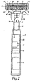
- the safety razor illustrated in the drawings has a handle 1 and a blade unit or partridge 2 detachably mounted on the upper end of the handle.
- the blade unit 2 includes a generally rectangular frame 3, and a plurality of blades 4, e.g. 3, 4 or 5 blades with substantially parallel sharp cutting edges, disposed in the frame and held in place by metal clips 5 positioned around the frame 3 at the opposite ends of the blade unit 2.
- a guard structure including a strip of elastomeric material is provided on the frame for contacting the skin in front of the blades, and a cap structure including a lubricating strip is provided on the frame for contacting the skin behind the blades during the performance of a shaving stroke.
- the frame is pivotally carried on a yoke member 8 having a pair of arms 9 which extend from a hub 10 and are journalled in opposite ends of the frame 3 so that the blade unit 2 can pivot relative to the handle 1 about an axis substantially parallel to the blade edges.
- the hub 10 is connected detachably to the end of the handle 1.
- the razor handle includes a main portion 12 intended to be gripped in the hand and a neck 14 extending upwardly from the main portion and to the free end of which the blade unit 2 is attached.
- the main or gripping portion 12 of the handle 1 includes an electrically conductive, e.g. metal casing 13 which serves as an electrode for electrical contact with the hand of a user as described in more detail below.
- a replaceable or rechargeable battery 15 housed within a battery compartment in the handle is a replaceable or rechargeable battery 15 which constitutes a power supply for an electronic control device 16 also accommodated with the handle.
- the battery 15 is electrically connected to the control device 16 through a power switch which is operable to interrupt power supply to the control device for conserving battery energy during periods when the razor is not being used.
- the power switch is arranged to be actuated by removing the razor from, and returning it to a razor holder on which the razor is intended to be stored when not in use.
- a known form of razor holder consists of a tray 18 as shown in Figures 3-5 , the tray 18 having on its upper side a saddle 19 adapted to receive and lightly grip the neck 14 of the razor handle 1.
- the razor handle 1 could be equipped with a mechanical switch so arranged for cooperation with the storage tray 18 that the switch is operated automatically when the razor is lifted away from the storage tray 18 for power to be supplied to the control device 16 from the battery 15, and to be actuated upon replacement of the razor on the tray to interrupt the power supply.
- a power switch in the form of a reed switch 20 located within the handle 1, the storage tray 18 being provided with a permanent magnet 21. The magnet is located in a position close to the saddle 19, and the reed switch is disposed in the handle 1 at or adjacent to the portion of the neck 14 adapted to be gripped in the saddle.
- the reed switch 20 When the razor is positioned close to the tray 18 the reed switch 20 is held open and there is no electrical power supply from the battery 15, as shown in Figure 3 , but when the razor is moved away from the tray the reed switch 20 closes and electrical power supply to the control device 16 is established.
- the control device 16 in a manner described in detail below, controls actuation of an electric motor 24 ( Figs. 2 and 3 ) housed within the handle 1 and having an output shaft with an eccentric weight 26 fastened thereon.
- an electric motor 24 Figs. 2 and 3
- energisation of the electric motor results in a high speed rotation of the eccentric weight 26 and thereby vibration of the razor, and the blade unit 2 in particular.
- a suitable vibration frequency is around 120 Hz.
- the blade unit 2 incorporates an electrode which is conveniently constituted by at least one and preferably includes all of the blades 4 of the blade unit. Electrical connection between the control device and this electrode 4 is achieved by the neck 14 of the handle 1 having a contact 30 arranged to project through the hub 10 of the yoke member 8 and to bear against a contact strip 32 fixed to the rear of the blade unit 2, the contact strip 32 having lateral wings 33 which extends to and are conductively connected to the metal blade retention clips 5, and these clips in turn having contact with blades 4.
- the blades 4 it is not essential to use the blades 4 as an electrode and a separate electrically conductive element could be provided on the blade unit in a position for contacting the skin when the blade unit 2 performs a shaving stroke.
- the contact 30 makes constant electrical contact with the contact strip 32 so that the electrical continuity between the electrode at the blade unit is not interrupted even during pivoting of the blade unit 2 on the handle 1 as tends to occur as the blade unit is applied to and moved across the skin.
- the contact 30 conveniently takes the form of a spring-loaded plunger for resisting pivotal movement of the blade unit away from a predetermined rest position.
- the contact 30 is shown connected electrically to the control device 16 by a wire conductor 35 which is led through the neck 14 of the handle 1.
- the frame 3 of the blade unit could be made of an electrically conductive material, such as a conductive plastics.
- the rear of the frame 3 could be plated, coated or printed with conductive material, have an adhesive metal foil applied to it, or have a metal element embedded therein, to provide electrical connection between the contact 30 and the clips 5, or to the electrode itself or another component in contact with the electrode.
- the frame may include an injection moulded metal part to provide the conductive path between the electrode and the contact 30, or water held in capillary grooves may be sufficient to ensure the electrical continuity.
- control device 16 it is possible for the control device 16 to be arranged to determine when the blade unit is immersed in water by sensing an electrical parameter between the electrode 4 on the blade unit 2 and the electrode formed by the metal casing 13 of the handle gripping portion 12. It is not necessarily essential for the blade unit 2 to be plunged into water so deeply that the water must contact the handle gripping portion 12 for the immersion of the blade unit into the water to be detected, as may be the case if it is known the body of water will be connected to earth and the casing of the gripping portion handle will also be connected to earth, such as by the razor user. As illustrated in Figure 7 , however, the razor includes a water detection probe 36 which extends along the exterior of the neck 14 of the handle.
- the probe 36 is electrically conductive and serves as an electrode, or an electrode extension in as much that it can be electrically connected to the metal casing 13 of the handle gripping portion 12.
- a separate electrical connection between the probe 36 and the control device 16 can alternatively be used.
- the control device 16 senses an electrical parameter, which may be electrical resistance or capacitance, between the blade electrode 4 and the probe electrode 36, and is responsive thereto to actuate the electric motor 24 to activate the vibration generator 26 when the blade unit 2 is immersed into a body water W so that both electrodes make contact with the water, the control device operating to turn off the power supply to the motor 24 when the blade unit 2 is lifted out of the water W.
- the operation of the control device 16 is described in detail below.
- control device 16 also functions as a touch sensitive device so that the motor 24 is actuated to drive the vibration generating eccentric weight 26 when a person holding the razor by the handle touches the blade unit 2 against the skin surface, e.g. at the start of a shaving stroke. Vibrating the blade unit as it moves across the skin can have a beneficial effect on the shaving performance. However, as soon as the blade unit is lifted away from the skin surface the vibration stops. It has been found that the discomfort perceived by users of vibrating razors applies for the most part only when the razor is held with the blade unit away from the body in free space and by the vibration occurring only when the razor is actually shaving and during rinsing of the blade unit, the user prejudices against vibrating razors are mostly eliminated.
- Fig. 8 is a schematic diagram to illustrate the function of control device 16.
- control device 16 comprises an oscillator 61, a comparator 62, motor driving circuitry 63 and first and second capacitors 64, 65.
- Control device 16 is additionally connected to two sensing electrodes which may be constituted by the blades 4 and the exterior casing 13 of the handle 1 respectively, or may be provided elsewhere on the exterior of the razor according to which condition is desired to be sensed.
- Motor driving circuitry 63 is connected to provide the drive current to motor 24.
- the power necessary to energise control device 16 is provided by battery 15 through a power switch.
- the power connections are omitted from Fig. 8 for clarity, it being understood that the following description of the operation of control device 16 is applicable to the condition when it is energised by the application of power from the battery.
- Oscillator 61 is configured to provide two oscillating signals on output lines 611 and 612 respectively.
- Output lines 611 and 612 are connected to line 66, which serves as a ground line for the circuitry, via first and second capacitors 64,65 respectively.
- Lines 611 and 612 further provide a pair of inputs to comparator 62.
- the comparator 62 is sensitive to changes in the relationship between its two inputs.
- the sensor electrodes are connected such that the relationship between the two inputs to the comparator changes when the electrical condition between the electrodes changes. As described above, this change may be generated according to whether both or only one of the electrodes are in contact with the body of a user, or according to whether the razor is immersed in water.
- the comparator switches the motor driver circuitry 63 on.
- the following description is mainly in terms of the electrical condition being altered by the electrodes both touching or being in close proximity to the user's body, it being understood, as just stated, that the change in electrical condition may be brought about by other conditions.
- line 612 is additionally connected to one of the sensing electrodes.
- the signals output by oscillator 61 on lines 611 and 612 have a first predetermined relationship at the input to comparator 62.
- both of the sensing electrodes are in contact with the body of a user some additional electrical connection is made between line 612 and ground line 66. This may be for instance capacitance additional to capacitor 53 and/or electrical resistance.
- the additional connection is effective to alter the characteristics of the signal on line 612 input to comparator 62. Accordingly the relationship between the two inputs change and the comparator 62 responds by activating motor driving circuitry 63 and so motor 24.
- control device 16 is responsive to both of the sensing electrodes being in contact with the body of the user.
- the sensitivity of the comparator control device 16 may also be responsive to other conditions.
- a user if a user is holding the shaving device and is therefore in contact with one of the electrodes, it may be sufficient to bring the other electrode close to but not touching his or her body.
- the proximity of the other electrode to the body is sufficient in this case for an additional capacitance to appear between lines 612 and 66 and so cause the above described change in the signals on line 612.
- the sensitivity of the comparator or other circuit proximity can be set to determine the approximate distance from the body at which this effect will occur. This may for instance be set to be approximately 10 mm.
- the invention may be configured to activate some device other than the motor 24 as well as or instead of the motor. In such a case other driving circuitry suitable for providing the current required by such other device may be provided.
- Fig. 9 illustrates a circuit implementation of the control device 16 of Fig. 8 . This is shown merely by way of illustration and many other ways of implementing the functionality of the control device 16 are possible.
- IC1:A, IC1:B and IC1:C are integrated circuit devices and other components are resistors, capacitors, diodes and transistors designated by the prefixes R, C, D and Q with exemplary values being shown in the Figure.
- RL1 is reed switch 20 operated by a magnet 21 in the tray 16 designed to hold the device when not in use.
- the switch RL1 is in the position illustrated such that the power from battery 15 connected to terminals T1,1 and T1,2 is applied to the circuit via the +3V rail, 71.
- Terminal T2,1 is connected to the exterior casing 13 of the handle 1 of the device to provide one of the two electrodes and the "ground" for the circuit.
- IC1:A forms the heart of the oscillator 61 and is configured with associated resistors R1,R2, capacitors C3,C4 and transistor Q1 to provide an oscillation output on lines 611 and 612. These provide the inputs to comparator 62, at the heart of which IC1:B, via resistor and capacitor networks R4,RV1 and C6, and R3 and C5.
- capacitor C6 starts to charge via resistor R4 and variable resistor RV1.
- capacitor C6 has the same value as capacitor C5, when nothing is connected to terminal T3,3 and RV1 is set so that the combination of R4 and RV1 is equivalent to R3, the charging rate of the two capacitors is the same. Therefore RV1 can be used to trim the circuit to ensure that, in this condition, C6 charges at least as quickly as C5 such the when the clock input to IC1:B goes high, the 'D' input from line 612 is also high. In this condition Q is always low and the motor driving circuitry 63 is not enabled.
- Terminal T3,3 is connected to the electrode 4 in the blade unit of the razor. Accordingly, when that electrode is brought into contact with or close proximity to the body of a user who is holding the handle connected to terminal T2,1, an additional path to ground is made, via a capacitor C7 and whatever resistance and capacitance the user's body has. This has the effect of slowing the charging rate of capacitor C6 such that, when the clock input of IC1:B goes high, the 'D' input is still low and so Q goes high.
- Motor 24 is connected to terminals T3,1 and T3,2 and is driven by standard motor driven circuit IC2. This circuit is enabled by the value of Q of IC1:B going high, thereby activating the motor 24 when an electrical condition between the electrodes alters, for instance when the head of the device is placed against the user's skin.
- control device functions so that the motor 24 stops immediately when the blade unit of the razor is moved out of contact with the skin.
- This is not essential and the control device can be arranged to provide a short delay of up to a few seconds, e.g. around 0.1 to 0.5 seconds, before turning off the power supply to the motor after contact between the blade unit and the skin of the user is interrupted, which may be beneficial in maintaining the vibration of the razor between shaving strokes performed in quick succession.
- the conductive casing 13 of the handle could be provided with a thin covering layer of insulating material so that there is a high capacitance and high resistance coupling between the hand of the user and the handle electrode.
- a manually operable switch mechanism can be included on the razor handle and be connected electrically in series with the switch 20, for use by a user who prefers not to use the storage tray 18 for holding the razor when it is not being used.
- This switch, or a different manually operable switch, such as an electronic toggle switch which turns on and/or off after a certain delay may be included in order to allow the razor user to select a non-vibrating mode, for example when trimming hair in awkward areas.
Landscapes
- Life Sciences & Earth Sciences (AREA)
- Forests & Forestry (AREA)
- Engineering & Computer Science (AREA)
- Mechanical Engineering (AREA)
- Dry Shavers And Clippers (AREA)
- Cosmetics (AREA)
- Thermotherapy And Cooling Therapy Devices (AREA)
- Filters For Electric Vacuum Cleaners (AREA)
Claims (16)
- Sicherheitsrasierer und ein Halter, an dem der Rasierer während Perioden der Nichtverwendung angebracht ist, wobei der Sicherheitsrasierer eine Klingeneinheit (2), die wenigstens eine Klinge (4) mit einer scharfen Schneide hat, und einen Griff (1) enthält, der die Klingeneinheit trägt, dadurch gekennzeichnet, dass der Sicherheitsrasierer einen Stromschalter (20) und eine elektrische Anordnung (16, 24) enthält, die während des Rasierens in Funktion ist und mit einer Stromquelle (15) über den Stromschalter verbunden werden kann, wobei der Stromschalter (20) in dem Rasierer enthalten und dazu eingerichtet ist betätigt zu werden, um eine Stromversorgung von der Stromquelle (15) zu der elektrischen Anordnung (16, 24) durch Trennung des Rasierers von dem Halter (18) zu gestatten.
- Sicherheitsrasierer und Halter nach Anspruch 1, wobei der Stromschalter in dem Griff des Rasierers enthalten ist.
- Sicherheitsrasierer und Halter nach Anspruch 2, wobei der Stromschalter ein mechanischer Schalter ist, der an dem Griff derart angeordnet ist, dass er durch Eingriff mit und Lösen von dem Rasiererhalter betätigt wird.
- Sicherheitsrasierer und Halter nach Anspruch 1 oder 2, wobei der Stromschalter (20) magnetisch betätigbar ist und der Rasiererhalter einen Magneten (21) für den Schalter enthält, der zu betätigen ist, wenn der Rasierer von dem Rasierhalter getrennt und auf diesem plaziert wird.
- Sicherheitsvorrichtung und Halter nach Anspruch 4, wobei der Stromschalter ein Reed-Schalter (20) ist.
- Sicherheitsrasierer und Halter nach Anspruch 3, 4 oder 5, wobei der Rasiererhalter (18) dazu eingerichtet ist, den Griff an oder benachbart der Stelle des Stromschalters (20) zu greifen.
- Sicherheitsrasierer und Halter nach einem der Ansprüche 1 bis 6, wobei der Rasiererhalter ein Tablett (18) ist, auf dem der Rasierer liegt.
- Sicherheitsrasierer und Halter nach einem der Ansprüche 1 bis 7, wobei die elektrische Anordnung eine elektrische Vorrichtung (24) und eine Steuervorrichtung (16) enthält, die den Betrieb der elektrischen Vorrichtung in Erwiderung auf einen Zustand steuert, der von der Steuervorrichtung erfasst wird.
- Sicherheitsrasierer und Halter nach Anspruch 8, wobei der Zustand, der von der Steuervorrichtung (16) erfasst wird, darin besteht, dass die Klingeneinheit mit der Hautoberfläche einer Person, die den Rasierer hält, in Kontakt oder in dichte Nähe zu dieser gebracht wird.
- Sicherheitsrasierer und Halter nach Anspruch 8, wobei der Zustand, der von der Steuervorrichtung (16) erfasst wird, darin besteht, dass die Klingeneinheit in einen Wasserkörper getaucht wird.
- Sicherheitsrasierer und Halter nach einem der Ansprüche 1 bis 10, wobei die Stromquelle eine Batterie (15) ist.
- Sicherheitsrasierer und Halter nach Anspruch 11, wobei sich die Batterie (15) in dem Griff (1) befindet.
- Sicherheitsrasierer und Halter nach einem der Ansprüche 1 bis 12, enthaltend eine Zeitgabevorrichtung, die die Stromversorgung zu der elektrischen Anordnung (16, 24) unterbricht, sofern der Rasierer innerhalb einer vorbestimmten Zeitdauer, nachdem er von dem Rasierhalter genommen wurde, nicht auf den Rasiererhalter (18) zurückgelegt wird.
- Sicherheitsrasierer und Halter nach Anspruch 13, wobei die Zeitgabevorrichtung durch Plazieren des Rasierers auf den Halter (18) rücksetzbar ist.
- Sicherheitsrasierer und Halter nach einem der Ansprüche 1 bis 14, enthaltend eine Anzeigeeinrichtung für die Signalgabe, wenn der elektrischen Anordnung von der Stromversorgung Strom zugeführt wird.
- Sicherheitsrasierer und Halter nach Anspruch 15, wobei die Anzeigeeinrichtung eine Lichtemittiervorrichtung ist, die sich am Griff befindet.
Applications Claiming Priority (3)
| Application Number | Priority Date | Filing Date | Title |
|---|---|---|---|
| GB0303869 | 2003-02-19 | ||
| GB0303869A GB2398534B (en) | 2003-02-19 | 2003-02-19 | Safety razors |
| PCT/GB2004/000684 WO2004073938A1 (en) | 2003-02-19 | 2004-02-19 | Safety razors |
Publications (2)
| Publication Number | Publication Date |
|---|---|
| EP1599322A1 EP1599322A1 (de) | 2005-11-30 |
| EP1599322B1 true EP1599322B1 (de) | 2010-07-28 |
Family
ID=9953338
Family Applications (1)
| Application Number | Title | Priority Date | Filing Date |
|---|---|---|---|
| EP04712609A Expired - Lifetime EP1599322B1 (de) | 2003-02-19 | 2004-02-19 | Sicherheitsrasierer |
Country Status (16)
| Country | Link |
|---|---|
| US (2) | US20060032054A1 (de) |
| EP (1) | EP1599322B1 (de) |
| JP (1) | JP4554592B2 (de) |
| KR (1) | KR20050100001A (de) |
| CN (1) | CN100381262C (de) |
| AT (1) | ATE475517T1 (de) |
| AU (1) | AU2004213227B2 (de) |
| BR (1) | BRPI0407510B1 (de) |
| CA (1) | CA2514852C (de) |
| DE (1) | DE602004028344D1 (de) |
| ES (1) | ES2349036T3 (de) |
| GB (1) | GB2398534B (de) |
| IL (1) | IL169960A (de) |
| MX (1) | MXPA05008745A (de) |
| NZ (1) | NZ541676A (de) |
| WO (1) | WO2004073938A1 (de) |
Families Citing this family (45)
| Publication number | Priority date | Publication date | Assignee | Title |
|---|---|---|---|---|
| US8615886B1 (en) * | 2004-05-06 | 2013-12-31 | Winthrop D. Childers | Shaving system with energy imparting device |
| US8327858B2 (en) | 2004-08-11 | 2012-12-11 | Elc Management Llc | Vibrating mascara applicator |
| US8317423B2 (en) | 2004-08-11 | 2012-11-27 | Elc Management Llc | Mascara for use with a vibrating applicator: compositions and methods |
| US7465114B2 (en) | 2004-08-11 | 2008-12-16 | Elc Management Llc | Vibrating mascara applicator, suitable compositions and method of use |
| FR2882506B1 (fr) | 2005-02-25 | 2007-05-18 | Oreal | Procede de maquillage au moyen d'un applicateur vibrant |
| JP2008534238A (ja) * | 2005-04-05 | 2008-08-28 | エバレデイ バツテリ カンパニー インコーポレーテツド | レーザカートリッジ |
| ATE503617T1 (de) * | 2005-04-05 | 2011-04-15 | Eveready Battery Inc | Rasiergerät mit beweglicher klinge |
| FI20055211A0 (fi) * | 2005-05-06 | 2005-05-06 | Nokia Corp | Radioresurssien hallinta FDMA järjestelmässä |
| US7905020B2 (en) * | 2005-08-29 | 2011-03-15 | Menachem Rozenkranc | Automatic shaving apparatus system |
| US7788810B2 (en) | 2006-07-24 | 2010-09-07 | Eveready Battery Company, Inc. | Shaving system having an umbilical |
| FR2906180B1 (fr) * | 2006-09-21 | 2008-12-05 | Bic Soc | Dispositif et procede de rasage a lame |
| US8061041B2 (en) * | 2007-02-14 | 2011-11-22 | The Gillette Company | Safety razor |
| US8230600B2 (en) * | 2007-09-17 | 2012-07-31 | The Gillette Company | Cartridge detachment sensor |
| US9308657B2 (en) * | 2008-05-30 | 2016-04-12 | The Gillette Company | Blade support for multi-blade razor cartridges |
| USD614507S1 (en) * | 2009-08-31 | 2010-04-27 | Eveready Battery Company, Inc. | Razor holder |
| USD628496S1 (en) * | 2010-03-24 | 2010-12-07 | American Safety Razor | Shaving razor tray |
| USD623962S1 (en) * | 2010-04-07 | 2010-09-21 | Eveready Battery Comapny, Inc. | Razor holder |
| EP2529899A1 (de) * | 2011-05-31 | 2012-12-05 | M. Yassir Marghich | Klinge und Klingenkopf |
| US9579809B2 (en) * | 2013-12-20 | 2017-02-28 | The Gillette Company Llc | Removable razor cartridge having magnetic elements |
| US9751228B2 (en) * | 2014-01-14 | 2017-09-05 | The Gillette Company Llc | Shaving cartridges having thermal sensors |
| EP3257470B1 (de) * | 2016-06-17 | 2019-07-24 | Ivoclar Vivadent AG | Lichthärtgerät mit steuerschaltung |
| US10652956B2 (en) | 2016-06-22 | 2020-05-12 | The Gillette Company Llc | Personal consumer product with thermal control circuitry and methods thereof |
| EP3351358B1 (de) | 2017-01-20 | 2019-11-20 | The Gillette Company LLC | Wärmelieferungselement für einen rasierer |
| JP2021516102A (ja) | 2018-03-30 | 2021-07-01 | ザ ジレット カンパニー リミテッド ライアビリティ カンパニーThe Gillette Company Llc | 枢動部分を有するかみそりハンドル |
| EP3774214B1 (de) * | 2018-03-30 | 2023-11-15 | The Gillette Company LLC | Rasierersystem |
| US11571828B2 (en) | 2018-03-30 | 2023-02-07 | The Gillette Company Llc | Shaving razor handle |
| EP3774235B1 (de) | 2018-03-30 | 2024-08-21 | The Gillette Company LLC | Rasierergriff mit einem schwenkbaren abschnitt |
| WO2019191231A1 (en) | 2018-03-30 | 2019-10-03 | The Gillette Company Llc | Razor handle with a pivoting portion |
| JP2021516135A (ja) | 2018-03-30 | 2021-07-01 | ザ ジレット カンパニー リミテッド ライアビリティ カンパニーThe Gillette Company Llc | 可動部材を有するかみそりハンドル |
| US11607820B2 (en) | 2018-03-30 | 2023-03-21 | The Gillette Company Llc | Razor handle with movable members |
| CA3092881A1 (en) | 2018-03-30 | 2019-10-03 | The Gillette Company Llc | Razor handle with movable members |
| USD874061S1 (en) | 2018-03-30 | 2020-01-28 | The Gillette Company Llc | Shaving razor cartridge |
| CN111819044B (zh) | 2018-03-30 | 2022-09-16 | 吉列有限责任公司 | 具有枢转部分的剃刀柄部 |
| EP3774218A1 (de) | 2018-03-30 | 2021-02-17 | The Gillette Company LLC | Rasierergriff mit einem schwenkbaren abschnitt |
| US11123888B2 (en) | 2018-03-30 | 2021-09-21 | The Gillette Company Llc | Razor handle with a pivoting portion |
| CN111801205B (zh) | 2018-03-30 | 2022-08-23 | 吉列有限责任公司 | 具有枢转部分的剃刀柄部 |
| JP2021516136A (ja) | 2018-03-30 | 2021-07-01 | ザ ジレット カンパニー リミテッド ライアビリティ カンパニーThe Gillette Company Llc | 可動部材を有するかみそりハンドル |
| WO2020165869A1 (en) | 2019-02-15 | 2020-08-20 | Church & Dwight Co., Inc. | Dermaplaning device and related system |
| CN110802639B (zh) * | 2019-11-15 | 2025-06-03 | 深圳素士科技股份有限公司 | 刀头组件及具有该刀头组件的剃须装置 |
| CN110802641B (zh) * | 2019-11-15 | 2025-06-03 | 深圳素士科技股份有限公司 | 刀头组件及包含该刀头组件的剃须器 |
| US20220088810A1 (en) * | 2020-09-21 | 2022-03-24 | Beauty Perspectives, LLC | Razor handle |
| KR102253716B1 (ko) * | 2020-10-08 | 2021-05-18 | 안나은 | 면도기 클리닝 장치 |
| USD1025484S1 (en) | 2021-10-29 | 2024-04-30 | Church & Dwight Co., Inc. | Hair removal device |
| USD1042965S1 (en) | 2022-05-19 | 2024-09-17 | Church & Dwight Co., Inc. | Hair removal device |
| EP4338901A1 (de) * | 2022-09-13 | 2024-03-20 | BIC Violex Single Member S.A. | Rasiersystem |
Family Cites Families (45)
| Publication number | Priority date | Publication date | Assignee | Title |
|---|---|---|---|---|
| US1681291A (en) * | 1927-05-25 | 1928-08-21 | Eugene E Glass | Sadiron receptacle |
| GB412596A (en) * | 1932-09-28 | 1934-06-28 | Frederick Albert Fraser | Improvements in and relating to cutting implements |
| US2256871A (en) * | 1939-07-01 | 1941-09-23 | David F Silver | Razor |
| US2474899A (en) * | 1945-10-04 | 1949-07-05 | Schick Inc | Shaver holder |
| US2511188A (en) * | 1947-10-25 | 1950-06-13 | Jack Van H Whipple | Electric shaver with blade sharpener |
| US3726009A (en) * | 1971-04-12 | 1973-04-10 | S Hackmyer | Self-lathering shaver |
| US3703765A (en) * | 1971-08-04 | 1972-11-28 | Gregorio A Perez | Disposable razor |
| US4077119A (en) * | 1977-02-16 | 1978-03-07 | Jose Manuel Sellera | Shaving device |
| JPS5835716B2 (ja) * | 1980-03-03 | 1983-08-04 | 松下電工株式会社 | 電気かみそりの電池カバ−取付構造 |
| US4366366A (en) * | 1980-09-05 | 1982-12-28 | Ekblad Carl A | Electric iron stand with time delay safety switch arrangement |
| JPS58149162U (ja) * | 1982-03-31 | 1983-10-06 | 日本電気ホームエレクトロニクス株式会社 | 電気かみそり |
| US4493975A (en) * | 1982-09-30 | 1985-01-15 | Yamada Electric Industries Co., Ltd. | Hang-up hair dryer |
| JPS59184778U (ja) * | 1983-05-25 | 1984-12-08 | フイリツプス工業振興株式会社 | 自動動作電気ひげそり器 |
| JPH0214759Y2 (de) * | 1985-09-18 | 1990-04-20 | ||
| US4744144A (en) * | 1986-04-02 | 1988-05-17 | Wellington Investments, Inc. | Oscillating razor |
| US4809432A (en) * | 1986-11-24 | 1989-03-07 | Shaverd Corp. | Disposable razor and emollient dispensing device |
| JPH0817861B2 (ja) * | 1987-05-15 | 1996-02-28 | 松下電工株式会社 | 電気かみそりの保護キャップ |
| JPH0632061Y2 (ja) * | 1987-05-22 | 1994-08-24 | 九州日立マクセル株式会社 | 電気かみそり |
| US5141349A (en) * | 1988-05-26 | 1992-08-25 | Procter & Gamble Company | Method and apparatus for treating the blade of a razor head |
| DE8909835U1 (de) * | 1989-08-17 | 1990-12-20 | Wilkinson Sword GmbH, 5650 Solingen | Naßrasierapparat |
| JP2714462B2 (ja) * | 1989-08-19 | 1998-02-16 | 松下電工株式会社 | 振動式かみそり |
| US5046104A (en) * | 1989-11-30 | 1991-09-03 | Cambridge Soundworks, Inc. | Loudspeaker system |
| US5299354A (en) * | 1990-10-11 | 1994-04-05 | The Gillette Company | Oscillating shaver |
| DE9200183U1 (de) * | 1992-01-09 | 1993-05-13 | Wilkinson Sword GmbH, 5650 Solingen | Naßrasiervorrichtung |
| US5347715A (en) * | 1993-09-14 | 1994-09-20 | Friedland Donald H | Blade shave counter |
| DE4402236C2 (de) * | 1994-01-26 | 1996-09-26 | Braun Ag | Verfahren zum Betrieb einer Reinigungsvorrichtung für den Scherkopf eines Trockenrasierapparates |
| DE4402237C1 (de) * | 1994-01-26 | 1995-03-09 | Braun Ag | Reinigungsvorrichtung zur Reinigung des Scherkopfs eines Trockenrasierapparats |
| US5463598A (en) * | 1994-08-12 | 1995-10-31 | Safesea Systems, Inc. | Man overboard alert and locating system |
| DE19606719C2 (de) * | 1996-02-23 | 1997-12-11 | Braun Ag | Verfahren zur Bestimmung der Verschmutzung eines Rasierapparates sowie Vorrichtung zur Durchführung des Verfahrens |
| US5956851A (en) * | 1996-04-10 | 1999-09-28 | The Gillette Company | Shaving system including handle and replaceable cartridges |
| US5782356A (en) * | 1996-04-30 | 1998-07-21 | International Business Machines Corporation | Container for storing and transporting fragile objects |
| US6102055A (en) * | 1997-01-27 | 2000-08-15 | Karnatz; Walter W. | Cation bead razor blade cleaning apparatus |
| US5782346A (en) * | 1997-02-19 | 1998-07-21 | The Gillette Company | Tray for a wet shaving razor |
| US6009623A (en) * | 1997-10-02 | 2000-01-04 | Warner-Lambert Company | Razor with in situ sensor |
| US6460251B1 (en) * | 1998-03-25 | 2002-10-08 | Pfizer Inc. | Razor system with worn blade indicator |
| JPH11353901A (ja) * | 1998-06-04 | 1999-12-24 | Aoki Denki Kogyo Kk | 非常脱出装置付き非常信号灯 |
| US6199239B1 (en) * | 1999-09-01 | 2001-03-13 | Herbert A. Dickerson | Toothbrush with audible reminder mechanism |
| JP2003520696A (ja) * | 2000-01-24 | 2003-07-08 | コーニンクレッカ フィリップス エレクトロニクス エヌ ヴィ | パーソナルケア又はツールとしての使用のためのハンドヘルド電気機器 |
| TWM245035U (en) * | 2000-02-23 | 2004-10-01 | Sanyo Electric Co | Electric shaver |
| DE10008937A1 (de) * | 2000-02-25 | 2001-08-30 | Philips Corp Intellectual Pty | Elektrischer Schaltkreis zur Ansteuerung von piezoelektrischen Antrieben |
| US6481104B1 (en) * | 2000-09-22 | 2002-11-19 | Sharper Image Corporation | Vibrating shaving systems |
| JP4528461B2 (ja) * | 2001-05-16 | 2010-08-18 | シチズン電子株式会社 | エレクトレットコンデンサマイクロフォン |
| JP2003024660A (ja) * | 2001-07-19 | 2003-01-28 | Kaijirushi Hamono Kaihatsu Center:Kk | 安全かみそりの保護カバ−及び安全かみそりのスタンド |
| US6750747B2 (en) * | 2002-08-29 | 2004-06-15 | Ljm Associates, Inc. | Proximity safety switch suitable for use in a hair dryer for disabling operation |
| US7654003B2 (en) * | 2003-02-19 | 2010-02-02 | The Gillette Company | Safety razors with charge indicator and power switch |
-
2003
- 2003-02-19 GB GB0303869A patent/GB2398534B/en not_active Expired - Fee Related
-
2004
- 2004-02-19 AT AT04712609T patent/ATE475517T1/de not_active IP Right Cessation
- 2004-02-19 CN CNB2004800046620A patent/CN100381262C/zh not_active Expired - Fee Related
- 2004-02-19 MX MXPA05008745A patent/MXPA05008745A/es active IP Right Grant
- 2004-02-19 JP JP2006502307A patent/JP4554592B2/ja not_active Expired - Fee Related
- 2004-02-19 AU AU2004213227A patent/AU2004213227B2/en not_active Ceased
- 2004-02-19 CA CA2514852A patent/CA2514852C/en not_active Expired - Fee Related
- 2004-02-19 NZ NZ541676A patent/NZ541676A/en unknown
- 2004-02-19 ES ES04712609T patent/ES2349036T3/es not_active Expired - Lifetime
- 2004-02-19 DE DE602004028344T patent/DE602004028344D1/de not_active Expired - Lifetime
- 2004-02-19 KR KR1020057015179A patent/KR20050100001A/ko not_active Abandoned
- 2004-02-19 BR BRPI0407510-2A patent/BRPI0407510B1/pt not_active IP Right Cessation
- 2004-02-19 WO PCT/GB2004/000684 patent/WO2004073938A1/en not_active Ceased
- 2004-02-19 EP EP04712609A patent/EP1599322B1/de not_active Expired - Lifetime
-
2005
- 2005-07-28 IL IL169960A patent/IL169960A/en not_active IP Right Cessation
- 2005-08-12 US US11/203,446 patent/US20060032054A1/en not_active Abandoned
-
2008
- 2008-09-15 US US12/283,642 patent/US20090019701A1/en not_active Abandoned
Also Published As
| Publication number | Publication date |
|---|---|
| JP4554592B2 (ja) | 2010-09-29 |
| NZ541676A (en) | 2006-12-22 |
| CN1750911A (zh) | 2006-03-22 |
| JP2006517820A (ja) | 2006-08-03 |
| WO2004073938A1 (en) | 2004-09-02 |
| GB0303869D0 (en) | 2003-03-26 |
| IL169960A (en) | 2010-06-30 |
| AU2004213227A1 (en) | 2004-09-02 |
| CA2514852C (en) | 2011-11-08 |
| GB2398534A (en) | 2004-08-25 |
| ES2349036T3 (es) | 2010-12-22 |
| US20090019701A1 (en) | 2009-01-22 |
| AU2004213227B2 (en) | 2008-08-07 |
| ATE475517T1 (de) | 2010-08-15 |
| US20060032054A1 (en) | 2006-02-16 |
| BRPI0407510A (pt) | 2006-02-14 |
| CA2514852A1 (en) | 2004-09-02 |
| DE602004028344D1 (de) | 2010-09-09 |
| CN100381262C (zh) | 2008-04-16 |
| EP1599322A1 (de) | 2005-11-30 |
| MXPA05008745A (es) | 2005-09-20 |
| KR20050100001A (ko) | 2005-10-17 |
| BRPI0407510B1 (pt) | 2014-06-10 |
| GB2398534B (en) | 2005-11-16 |
Similar Documents
| Publication | Publication Date | Title |
|---|---|---|
| EP1599322B1 (de) | Sicherheitsrasierer | |
| EP1597030B2 (de) | Sicherheitsrasierer | |
| US7654003B2 (en) | Safety razors with charge indicator and power switch | |
| EP1597031B1 (de) | Sicherheitsrasierer mit näherungs- oder berührungsempfindlicher Steuerung | |
| EP1599320B1 (de) | Sicherheitsrasierer | |
| HK1124804B (en) | Hand held appliances |
Legal Events
| Date | Code | Title | Description |
|---|---|---|---|
| PUAI | Public reference made under article 153(3) epc to a published international application that has entered the european phase |
Free format text: ORIGINAL CODE: 0009012 |
|
| 17P | Request for examination filed |
Effective date: 20050902 |
|
| AK | Designated contracting states |
Kind code of ref document: A1 Designated state(s): AT BE BG CH CY CZ DE DK EE ES FI FR GB GR HU IE IT LI LU MC NL PT RO SE SI SK TR |
|
| AX | Request for extension of the european patent |
Extension state: AL LT LV MK |
|
| DAX | Request for extension of the european patent (deleted) | ||
| 17Q | First examination report despatched |
Effective date: 20070822 |
|
| GRAP | Despatch of communication of intention to grant a patent |
Free format text: ORIGINAL CODE: EPIDOSNIGR1 |
|
| GRAS | Grant fee paid |
Free format text: ORIGINAL CODE: EPIDOSNIGR3 |
|
| GRAA | (expected) grant |
Free format text: ORIGINAL CODE: 0009210 |
|
| AK | Designated contracting states |
Kind code of ref document: B1 Designated state(s): AT BE BG CH CY CZ DE DK EE ES FI FR GB GR HU IE IT LI LU MC NL PT RO SE SI SK TR |
|
| REG | Reference to a national code |
Ref country code: GB Ref legal event code: FG4D |
|
| REG | Reference to a national code |
Ref country code: CH Ref legal event code: EP |
|
| REG | Reference to a national code |
Ref country code: IE Ref legal event code: FG4D |
|
| REF | Corresponds to: |
Ref document number: 602004028344 Country of ref document: DE Date of ref document: 20100909 Kind code of ref document: P |
|
| REG | Reference to a national code |
Ref country code: SE Ref legal event code: TRGR |
|
| REG | Reference to a national code |
Ref country code: GR Ref legal event code: EP Ref document number: 20100402098 Country of ref document: GR |
|
| REG | Reference to a national code |
Ref country code: NL Ref legal event code: T3 |
|
| REG | Reference to a national code |
Ref country code: ES Ref legal event code: FG2A Effective date: 20101210 |
|
| PG25 | Lapsed in a contracting state [announced via postgrant information from national office to epo] |
Ref country code: AT Free format text: LAPSE BECAUSE OF FAILURE TO SUBMIT A TRANSLATION OF THE DESCRIPTION OR TO PAY THE FEE WITHIN THE PRESCRIBED TIME-LIMIT Effective date: 20100728 Ref country code: FI Free format text: LAPSE BECAUSE OF FAILURE TO SUBMIT A TRANSLATION OF THE DESCRIPTION OR TO PAY THE FEE WITHIN THE PRESCRIBED TIME-LIMIT Effective date: 20100728 |
|
| PG25 | Lapsed in a contracting state [announced via postgrant information from national office to epo] |
Ref country code: SI Free format text: LAPSE BECAUSE OF FAILURE TO SUBMIT A TRANSLATION OF THE DESCRIPTION OR TO PAY THE FEE WITHIN THE PRESCRIBED TIME-LIMIT Effective date: 20100728 Ref country code: PT Free format text: LAPSE BECAUSE OF FAILURE TO SUBMIT A TRANSLATION OF THE DESCRIPTION OR TO PAY THE FEE WITHIN THE PRESCRIBED TIME-LIMIT Effective date: 20101129 Ref country code: CY Free format text: LAPSE BECAUSE OF FAILURE TO SUBMIT A TRANSLATION OF THE DESCRIPTION OR TO PAY THE FEE WITHIN THE PRESCRIBED TIME-LIMIT Effective date: 20100728 Ref country code: BG Free format text: LAPSE BECAUSE OF FAILURE TO SUBMIT A TRANSLATION OF THE DESCRIPTION OR TO PAY THE FEE WITHIN THE PRESCRIBED TIME-LIMIT Effective date: 20101028 |
|
| PG25 | Lapsed in a contracting state [announced via postgrant information from national office to epo] |
Ref country code: DK Free format text: LAPSE BECAUSE OF FAILURE TO SUBMIT A TRANSLATION OF THE DESCRIPTION OR TO PAY THE FEE WITHIN THE PRESCRIBED TIME-LIMIT Effective date: 20100728 |
|
| PG25 | Lapsed in a contracting state [announced via postgrant information from national office to epo] |
Ref country code: CZ Free format text: LAPSE BECAUSE OF FAILURE TO SUBMIT A TRANSLATION OF THE DESCRIPTION OR TO PAY THE FEE WITHIN THE PRESCRIBED TIME-LIMIT Effective date: 20100728 Ref country code: EE Free format text: LAPSE BECAUSE OF FAILURE TO SUBMIT A TRANSLATION OF THE DESCRIPTION OR TO PAY THE FEE WITHIN THE PRESCRIBED TIME-LIMIT Effective date: 20100728 Ref country code: SK Free format text: LAPSE BECAUSE OF FAILURE TO SUBMIT A TRANSLATION OF THE DESCRIPTION OR TO PAY THE FEE WITHIN THE PRESCRIBED TIME-LIMIT Effective date: 20100728 Ref country code: RO Free format text: LAPSE BECAUSE OF FAILURE TO SUBMIT A TRANSLATION OF THE DESCRIPTION OR TO PAY THE FEE WITHIN THE PRESCRIBED TIME-LIMIT Effective date: 20100728 |
|
| PGFP | Annual fee paid to national office [announced via postgrant information from national office to epo] |
Ref country code: IT Payment date: 20110219 Year of fee payment: 8 Ref country code: NL Payment date: 20110216 Year of fee payment: 8 Ref country code: FR Payment date: 20110201 Year of fee payment: 8 Ref country code: SE Payment date: 20110209 Year of fee payment: 8 |
|
| PLBE | No opposition filed within time limit |
Free format text: ORIGINAL CODE: 0009261 |
|
| STAA | Information on the status of an ep patent application or granted ep patent |
Free format text: STATUS: NO OPPOSITION FILED WITHIN TIME LIMIT |
|
| 26N | No opposition filed |
Effective date: 20110429 |
|
| PGFP | Annual fee paid to national office [announced via postgrant information from national office to epo] |
Ref country code: ES Payment date: 20110222 Year of fee payment: 8 Ref country code: BE Payment date: 20110309 Year of fee payment: 8 |
|
| REG | Reference to a national code |
Ref country code: DE Ref legal event code: R097 Ref document number: 602004028344 Country of ref document: DE Effective date: 20110429 |
|
| PG25 | Lapsed in a contracting state [announced via postgrant information from national office to epo] |
Ref country code: MC Free format text: LAPSE BECAUSE OF NON-PAYMENT OF DUE FEES Effective date: 20110228 |
|
| REG | Reference to a national code |
Ref country code: CH Ref legal event code: PL |
|
| PG25 | Lapsed in a contracting state [announced via postgrant information from national office to epo] |
Ref country code: CH Free format text: LAPSE BECAUSE OF NON-PAYMENT OF DUE FEES Effective date: 20110228 Ref country code: LI Free format text: LAPSE BECAUSE OF NON-PAYMENT OF DUE FEES Effective date: 20110228 |
|
| REG | Reference to a national code |
Ref country code: IE Ref legal event code: MM4A |
|
| PG25 | Lapsed in a contracting state [announced via postgrant information from national office to epo] |
Ref country code: IE Free format text: LAPSE BECAUSE OF NON-PAYMENT OF DUE FEES Effective date: 20110219 |
|
| BERE | Be: lapsed |
Owner name: THE GILLETTE CY Effective date: 20120228 |
|
| REG | Reference to a national code |
Ref country code: NL Ref legal event code: V1 Effective date: 20120901 |
|
| PG25 | Lapsed in a contracting state [announced via postgrant information from national office to epo] |
Ref country code: SE Free format text: LAPSE BECAUSE OF NON-PAYMENT OF DUE FEES Effective date: 20120220 |
|
| REG | Reference to a national code |
Ref country code: FR Ref legal event code: ST Effective date: 20121031 |
|
| PG25 | Lapsed in a contracting state [announced via postgrant information from national office to epo] |
Ref country code: IT Free format text: LAPSE BECAUSE OF NON-PAYMENT OF DUE FEES Effective date: 20120219 |
|
| PG25 | Lapsed in a contracting state [announced via postgrant information from national office to epo] |
Ref country code: BE Free format text: LAPSE BECAUSE OF NON-PAYMENT OF DUE FEES Effective date: 20120228 |
|
| PG25 | Lapsed in a contracting state [announced via postgrant information from national office to epo] |
Ref country code: NL Free format text: LAPSE BECAUSE OF NON-PAYMENT OF DUE FEES Effective date: 20120901 Ref country code: FR Free format text: LAPSE BECAUSE OF NON-PAYMENT OF DUE FEES Effective date: 20120229 |
|
| PG25 | Lapsed in a contracting state [announced via postgrant information from national office to epo] |
Ref country code: LU Free format text: LAPSE BECAUSE OF NON-PAYMENT OF DUE FEES Effective date: 20110219 |
|
| REG | Reference to a national code |
Ref country code: ES Ref legal event code: FD2A Effective date: 20130709 |
|
| PG25 | Lapsed in a contracting state [announced via postgrant information from national office to epo] |
Ref country code: ES Free format text: LAPSE BECAUSE OF NON-PAYMENT OF DUE FEES Effective date: 20120220 |
|
| PG25 | Lapsed in a contracting state [announced via postgrant information from national office to epo] |
Ref country code: HU Free format text: LAPSE BECAUSE OF FAILURE TO SUBMIT A TRANSLATION OF THE DESCRIPTION OR TO PAY THE FEE WITHIN THE PRESCRIBED TIME-LIMIT Effective date: 20100728 |
|
| REG | Reference to a national code |
Ref country code: DE Ref legal event code: R081 Ref document number: 602004028344 Country of ref document: DE Owner name: THE GILLETTE COMPANY LLC (N. D. GES. D. STAATE, US Free format text: FORMER OWNER: THE GILLETTE CO., BOSTON, MASS., US |
|
| REG | Reference to a national code |
Ref country code: GB Ref legal event code: 732E Free format text: REGISTERED BETWEEN 20170622 AND 20170628 |
|
| PGFP | Annual fee paid to national office [announced via postgrant information from national office to epo] |
Ref country code: GR Payment date: 20180116 Year of fee payment: 15 Ref country code: TR Payment date: 20180212 Year of fee payment: 15 |
|
| PGFP | Annual fee paid to national office [announced via postgrant information from national office to epo] |
Ref country code: GB Payment date: 20190213 Year of fee payment: 16 |
|
| PG25 | Lapsed in a contracting state [announced via postgrant information from national office to epo] |
Ref country code: GR Free format text: LAPSE BECAUSE OF NON-PAYMENT OF DUE FEES Effective date: 20190904 |
|
| GBPC | Gb: european patent ceased through non-payment of renewal fee |
Effective date: 20200219 |
|
| PG25 | Lapsed in a contracting state [announced via postgrant information from national office to epo] |
Ref country code: GB Free format text: LAPSE BECAUSE OF NON-PAYMENT OF DUE FEES Effective date: 20200219 |
|
| PG25 | Lapsed in a contracting state [announced via postgrant information from national office to epo] |
Ref country code: TR Free format text: LAPSE BECAUSE OF NON-PAYMENT OF DUE FEES Effective date: 20190219 |
|
| PGFP | Annual fee paid to national office [announced via postgrant information from national office to epo] |
Ref country code: DE Payment date: 20221230 Year of fee payment: 20 |
|
| P01 | Opt-out of the competence of the unified patent court (upc) registered |
Effective date: 20230430 |
|
| REG | Reference to a national code |
Ref country code: DE Ref legal event code: R071 Ref document number: 602004028344 Country of ref document: DE |