EP1598681A2 - Composant optique ayant une surface courbée et un revêtement multicouche - Google Patents
Composant optique ayant une surface courbée et un revêtement multicouche Download PDFInfo
- Publication number
- EP1598681A2 EP1598681A2 EP05008873A EP05008873A EP1598681A2 EP 1598681 A2 EP1598681 A2 EP 1598681A2 EP 05008873 A EP05008873 A EP 05008873A EP 05008873 A EP05008873 A EP 05008873A EP 1598681 A2 EP1598681 A2 EP 1598681A2
- Authority
- EP
- European Patent Office
- Prior art keywords
- layer
- optical component
- crystal
- substrate surface
- component according
- Prior art date
- Legal status (The legal status is an assumption and is not a legal conclusion. Google has not performed a legal analysis and makes no representation as to the accuracy of the status listed.)
- Withdrawn
Links
Images


Classifications
-
- G—PHYSICS
- G02—OPTICS
- G02B—OPTICAL ELEMENTS, SYSTEMS OR APPARATUS
- G02B5/00—Optical elements other than lenses
- G02B5/08—Mirrors
- G02B5/0816—Multilayer mirrors, i.e. having two or more reflecting layers
- G02B5/0825—Multilayer mirrors, i.e. having two or more reflecting layers the reflecting layers comprising dielectric materials only
- G02B5/0833—Multilayer mirrors, i.e. having two or more reflecting layers the reflecting layers comprising dielectric materials only comprising inorganic materials only
-
- G—PHYSICS
- G02—OPTICS
- G02B—OPTICAL ELEMENTS, SYSTEMS OR APPARATUS
- G02B1/00—Optical elements characterised by the material of which they are made; Optical coatings for optical elements
- G02B1/02—Optical elements characterised by the material of which they are made; Optical coatings for optical elements made of crystals, e.g. rock-salt, semi-conductors
-
- G—PHYSICS
- G02—OPTICS
- G02B—OPTICAL ELEMENTS, SYSTEMS OR APPARATUS
- G02B1/00—Optical elements characterised by the material of which they are made; Optical coatings for optical elements
- G02B1/10—Optical coatings produced by application to, or surface treatment of, optical elements
- G02B1/11—Anti-reflection coatings
- G02B1/113—Anti-reflection coatings using inorganic layer materials only
-
- G—PHYSICS
- G02—OPTICS
- G02B—OPTICAL ELEMENTS, SYSTEMS OR APPARATUS
- G02B3/00—Simple or compound lenses
-
- G—PHYSICS
- G02—OPTICS
- G02B—OPTICAL ELEMENTS, SYSTEMS OR APPARATUS
- G02B5/00—Optical elements other than lenses
- G02B5/08—Mirrors
- G02B5/0891—Ultraviolet [UV] mirrors
-
- G—PHYSICS
- G02—OPTICS
- G02B—OPTICAL ELEMENTS, SYSTEMS OR APPARATUS
- G02B5/00—Optical elements other than lenses
- G02B5/08—Mirrors
- G02B5/10—Mirrors with curved faces
-
- Y—GENERAL TAGGING OF NEW TECHNOLOGICAL DEVELOPMENTS; GENERAL TAGGING OF CROSS-SECTIONAL TECHNOLOGIES SPANNING OVER SEVERAL SECTIONS OF THE IPC; TECHNICAL SUBJECTS COVERED BY FORMER USPC CROSS-REFERENCE ART COLLECTIONS [XRACs] AND DIGESTS
- Y10—TECHNICAL SUBJECTS COVERED BY FORMER USPC
- Y10S—TECHNICAL SUBJECTS COVERED BY FORMER USPC CROSS-REFERENCE ART COLLECTIONS [XRACs] AND DIGESTS
- Y10S117/00—Single-crystal, oriented-crystal, and epitaxy growth processes; non-coating apparatus therefor
- Y10S117/901—Levitation, reduced gravity, microgravity, space
- Y10S117/902—Specified orientation, shape, crystallography, or size of seed or substrate
Definitions
- the invention relates to an optical component having a substrate, on which at least one curved substrate surface is formed, which defines an optical axis of the optical component, wherein the substrate surface is coated with an ultraviolet light region at a design wavelength ⁇ 0 effective multilayer coating, the one on the substrate surface applied first layer of a first dielectric material and at least one applied to the first layer second layer of a second dielectric material.
- the invention also relates to an optical imaging system comprising at least one such component and to a method for producing optical components.
- ⁇ 0 In many areas of application of optical systems, the demand for high-performance optical components whose optical properties are optimized for design wavelengths ⁇ 0 , which lie in the deep ultraviolet range (DUV) or in the vacuum ultraviolet range (VUV), in particular in the wavelength range between about 120 nm and approx 260 nm. Radiation from this wavelength range is used, for example, in microlithography systems for producing highly integrated semiconductor components or other finely structured components with the aid of wafer steppers or wafer scanners.
- a light source for example a laser, illuminates a mask (reticle) via an illumination system, the image of which is imaged by means of a projection system onto a semiconductor wafer coated with a photoresist layer.
- NA numerical aperture
- HR layer highly reflective coating
- concave rear surface mirrors (Mangin level) in catadioptric systems is also known.
- fluoride crystal materials such as monocrystalline calcium fluoride (CaF 2 ) or barium fluoride (BaF 2 ).
- dielectric multilayer coatings with alternating high-refractive and low-refractive single layers are also limited.
- fluoridic materials are preferred because of their high transparency and low material-specific absorbance.
- Lanthanum fluoride (LaF 3 ) is often used as high refractive index and magnesium fluoride (MgF 2 ) as a low refractive index dielectric material.
- the lanthanum fluoride layer had a polycrystalline structure with random crystallization orientation.
- VUV vacuum ultraviolet
- WO 03/009015 optical components with calcium fluoride substrates presented, whose surfaces parallel or at an angle of at most 30 ° to a (111) plane of the crystal material. These Substrate surfaces are covered with an epitaxially grown layer from lanthanum fluoride, which has a dense, low-defect structure, a high refractive index and low absorption losses should have.
- the patent US 6,261,696 B1 describes a coating process describe it with the use of fluoride-containing substrate materials should be possible with a coating production with Help of sputtering technique to avoid the formation of color centers.
- a layer is formed on the substrate surface as the first layer Silica, beryllium oxide, magnesium oxide or magnesium fluoride with a layer thickness of 30 nm or less applied.
- the protective layer should a penetration of the plasma into the substrate material and a thereby preventing production of color centers.
- an optical component having a substrate on which is formed at least one curved substrate surface defining an optical axis of the optical component, the substrate surface having an ultraviolet region at a design wavelength ⁇ 0 effective multilayer coating is applied, which comprises a first layer applied to the substrate surface of a first dielectric material and at least one applied to the first layer second layer of a second dielectric material, wherein the substrate consists of a crystal material, which is parallel to the optical axis extending axially parallel crystal direction and perpendicular to edge zones of the curved substrate surface standing edge crystal directions, wherein an angle between the paraxial crystal direction and the edge crystal directions is at least 17 ° and the e
- the first layer has a substantially texture-free layer structure.
- the inventors have recognized that strongly curved substrate surfaces of calcium fluoride lenses or others with a substrate single crystalline crystal material constructed optical components for the growing up during the coating process first layer under certain conditions may represent an anisotropic surface, the corresponding anisotropy of the optical properties of Multilayer coating causes, provided the first layer largely grows epitaxially and thus the anisotropy of the substrate surface continues into the properties of multilayer coating.
- the observed anisotropy of the substrate surface occurs especially then to a substantial extent, if due to the curvature and / or the diameter of the substrate surface in different surface areas the substrate surface different, low indexed Lattice planes of the crystal material more or less parallel to the local course of the substrate surface run.
- the growth conditions of the first layer clearly from adjacent surface areas of the Substrate surface, where highly indexed planes to the substrate surface bump. These differences usually cause anisotropy the growth conditions. Accordingly, the anisotropy becomes then more pronounced when the curved substrate surface so runs that at least two different Surface areas of the substrate surface low indexed crystal directions of the crystal material perpendicular to the substrate surface stand.
- the angle is between a ⁇ 100> direction and an adjacent ⁇ 110> direction 45 °, the angle between a ⁇ 100> direction and an adjacent ⁇ 111> direction 54.7 ° and the angle between a ⁇ 111> direction and a adjacent ⁇ 110> direction 35.3 °. Therefore, for example, at a substrate whose axially parallel crystal direction is a ⁇ 111> direction is in the peripheral zone at three in the circumferential direction (azimuthal direction) Placed places a surface orientation substantially perpendicular to a ⁇ 110> direction when the substrate surface is so strongly curved and / or has such a large diameter, that the curvature is sufficient, so that an angle between the paraxial Crystal direction and the edge crystal directions at least 35.3 °.
- the axially parallel crystal direction lies near a low-indexed crystal direction of the crystal material.
- it may be less than 15 degrees or less than 10 degrees from a ⁇ 111>, ⁇ 110> or ⁇ 100> direction of the crystal material differ.
- those components in which the Deviation angle less than 5 ° or less than 2 ° or less is 1 ° from one of these low indexed crystal directions in high performance optics for microlithography and others UV high performance optics common and can better by the invention be used as previously.
- the first layer consists of a low refractive index material, in particular substantially magnesium fluoride. It has been found that this material can be applied so as to provide a substantially disordered backing for the second layer thereon and optionally for subsequent layers so that epitaxial growth of the coating can be suppressed.
- a low refractive index material in particular substantially magnesium fluoride.
- other low refractive dielectric materials for example, aluminum fluoride, lithium fluoride, chiolite (Na 5 Al 3 F 14 ) or cryolite (Na 3 AlF 6 ) or silicon dioxide (SiO 2 ) may be used for the first layer.
- the coating process can be controlled in such a way that the first layer grows up amorphously at least in certain areas, that is, at least locally, it has no defined crystal structure.
- the process temperature is set to very low temperatures in the coating process, in particular to temperatures of 180 ° C or below.
- the surface diffusion of the incident layer particles on the substrate can be reduced, so that the possibility of reorganization inhibited and the above-described, caused by heteroepitaxy effects can be reduced or avoided.
- a largely disordered first layer of calcium fluoride may be applied as an alternative to a first layer of magnesium fluoride.
- This amorphous CaF 2 layer has a low refractive index as crystalline CaF 2 , so it is slightly low refractive with respect to such a substrate.
- the coating process can also be carried out so that the first layer a polycrystalline layer with a variety of Crystallites with essentially random distribution of crystal orientations is. Due to the polycrystalline first layer, the disadvantageous Anisotropy of the hetero-coating properties as well be suppressed.
- a layer design it is provided in some embodiments to first apply to the substrate surface another high refractive index material, for example, gadolinium fluoride of suitable thickness before lanthanum fluoride is applied as another layer material. Both layers can then serve together as a high refractive index layer with inhomogeneous refractive index, which, however, unlike a pure layer of lanthanum fluoride has the advantage of a disordered layer structure.
- another high refractive index material for example, gadolinium fluoride of suitable thickness before lanthanum fluoride is applied as another layer material.
- gadolinium fluoride for example, alumina (Al 2 O 3 ), erbium fluoride (ErF 3 ), holmium fluoride (HoF 3 ), neodymium fluoride (NdF 2 ), samarium fluoride (SmF 3 ), terbium fluoride (TbF 3 ), titanium fluoride (TiF 3 ), yttrium fluoride (YF 3 ), ytterbium fluoride (YbF 3 ) or mixtures thereof.
- alumina Al 2 O 3
- ErF 3 erbium fluoride
- HoF 3 holmium fluoride
- NdF 2 neodymium fluoride
- SmF 3 samarium fluoride
- TbF 3 terbium fluoride
- TiF 3 titanium fluoride
- YF 3 yttrium fluoride
- YbF 3 ytterbium fluoride
- the optical component is one in preferred embodiments Lens with a substrate of one for the radiation of the design wavelength transparent crystal material, wherein the multilayer coating designed as a multilayer antireflection coating. That's it possible, one coated with a multilayer antireflective coating optical component with a location-dependent transmittance too obtained, over the cross section of the substrate surface, a variation width of less than 1 percentage point.
- the invention is also in the production of highly reflective Mirrors usable where a mirror substrate of a crystal material with curved substrate surface a highly reflective dielectric multilayer reflective coating is applied.
- a mirror substrate of a crystal material with curved substrate surface a highly reflective dielectric multilayer reflective coating is applied.
- concave mirrors are considered as the rear surface mirrors are designed.
- mangin levels can e.g. in catadioptric systems for color correction and correction of field curvature be used.
- the transparent mirror substrate can be the Have a negative meniscus lens shape.
- the invention also relates to an optical imaging system for imaging a first field surface in an optically conjugate second Field surface with multiple optical components, where at least one of the optical components is constructed according to the invention.
- lenses are at least a strongly curved substrate surface near one Field surface where the marginal ray height of the figure small against the Main beam height is. This area is also used here as a field-related area designated.
- the optical component with the according to the Invention coated, curved substrate surface arranged so be that at this surface angle of incidence of the incident Radiation occur, the incidence angle of more than 30 ° include.
- Example lighting systems shown as a Rema lens designated imaging system, with which the exit surface an upstream rod integrator in the exit plane of the illumination system is imaged on a reticle located there.
- a concave meniscus lens provided, in which both the entrance surface and the exit surface are strongly curved.
- Projection objectives for microlithography often have a plano-convex lens as the last lens in front of the image plane, whose entrance surface can be strongly curved. The invention is thus in the field of microlithography in both lighting systems and also advantageous for projection lenses.
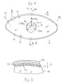
- FIG. 1 shows an exemplary embodiment of an optical component according to the invention, which is designed as a biconvex positive lens 10 with lens surfaces strongly curved on both sides.
- the lens has a substrate 11 made of monocrystalline calcium fluoride (CaF 2 ) on which two highly convex curved, spherical substrate surfaces 12, 13 are formed. The centers of curvature of the substrate surfaces define the optical axis 14 of the lens 10.
- the lens for the lens (lens blank) is cut from a circular cylindrical calcium fluoride single crystal whose longitudinal axis defined by the growth direction is substantially parallel to a ⁇ 111> direction of the crystal material.
- Such lenses are commonly used in illumination systems or projection objectives for microlithography projection equipment operating with deep ultraviolet (DUV) or vacuum ultraviolet (VUV) radiation. They are used, for example, in systems with 193 nm operating wavelength in combination with lenses made of synthetic quartz glass for color correction. Due to the lower tendency of calcium fluoride to radiation-induced density change (in particular compaction) compared to synthetic quartz glass calcium fluoride lenses are also used in areas of high energy density radiation, which often lie in the vicinity of field levels of imaging in optical imaging systems (object area, image area, area of a real intermediate image).
- DUV deep ultraviolet
- VUV vacuum ultraviolet
- the crystallographic orientation of the crystal material implies that the Substrate surfaces 12, 13 in the center region M of the lens, i. in the Near the optical axis 14, substantially parallel to (111) network levels of the crystal material. Such a network level is within of the schematically represented unit cube 15 of the crystal material shown schematically by dashed lines. Due to the strong curvature the substrate surfaces having a radius of curvature R, which may be of the order of the diameter D of the lens, deviates the orientation of the curved substrate surface in the edge region RS of the substrate surface strongly from a ⁇ 111> orientation from. In the example, one is perpendicular to the edge of the curved substrate surface standing edge crystal direction 20 in an angle of significantly more than 30 ° to the axis-parallel ⁇ 111> crystal direction.
- a perpendicular to a ⁇ 110> -direction (110) -plane is in Unit cube 15 shown in phantom.
- a conventionally coated reference lens which is a ⁇ 111> -oriented calcium fluoride substrate
- Both substrate surfaces were coated with a 2-layer antireflective coating in which the first layer of lanthanum fluoride (LaF 3 ) lying directly on the substrate surface and the second layer of magnesium fluoride (MgF 2 ) lying above it.
- the layers of the 2-layer were conventionally deposited by electron beam evaporation at a coating temperature of about T> 200 ° C.
- the optical layer thicknesses (n - d) of both layers were respectively (0.25) ⁇ 0 , where ⁇ 0 is the design wavelength of the coating (here 157 nm), n is the refractive index of the layer material and d is the geometric layer thickness of the layer material.
- the optical properties determined during concentricity measurements.
- the lens is rotated about its optical axis and the optical Properties are each at a constant height (radial distance to optical axis) measured with variation of the azimuth angle ⁇ .
- Measurements were both in the edge area RS of the coated Substrate surface as well as in the zone area Z (between optical Axis and edge region) and in the middle region M near the optical Axis performed.
- a "border area” is an annular area at the outer edge of the coating, whose width is in Radial direction is a maximum of 20% of the radius of the coating.
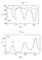
- FIG. 3 is the Result of a concentricity transmission measurement on both sides conventional way (2-layer, T> 200 ° C) coated lens shown.
- T the transmission
- curve Z the transmission of the zone
- ⁇ 70 °, 190 ° and 310 ° in the angular distance of each 120 ° local minima in the transmission process recognizable.
- Curve RS Edge measurement enter these transmission minima to a Multiple reinforced.
- the modulation of the transmission lies here in the order of about 5 percentage points. This magnitude can be used for applications in high-performance optics, for example Microlithography projection exposure equipment, unacceptable.
- FIG. 4 shows the results of corresponding concentricity measurements for the Reflectance R of the antireflection coating in the edge area RS. At the geometric places with transmission minima are pronounced Maxima of the reflectance R on, with its modulation in one Magnitude of about 3 - 4 percentage points. This makes it clear that much of the modulation of the transmission ( Figure 3) by reflection losses is caused.
- Fig. 5 it can be seen that the wavelength ⁇ , in which the Minimum of the reflectance of the antireflective coating is varies between about 164 nm and about 200 nm. At the spectral width the anti-reflection effect of the conventional two-layer antireflective coatings used So that can be tight specifications for the Reflection barely adhered to.
- the strongly modulated curve (T> 200 ° C.) shows the curve for the reference lens REF shown in FIG. 4, which was coated with a LaF 3 / MgF 2 -addition system.
- the weaker modulated curve (T ⁇ 180 ° C) shows the results for a corresponding LaF 3 / MgF 2 two-layer system applied at a coating temperature T ⁇ 180 ° C. It is obvious that the lower coating temperature leads to a significantly lower modulation with a modulation height of about 1 percentage point.
- the low coating temperature apparently reduces the mobility or surface diffusion of the deposited particles such that reorganization of the particles to form an epitaxial first preferred direction layer is inhibited or reduced to substantially unordered, substantial texture-free first layer is formed.
- this may be partly amorphous and / or polycrystalline, with the crystallites of the polycrystalline first layer being essentially randomly oriented so that the formation of a preferred direction is avoided.
- the first layer 51 applied directly to the substrate surface 13 consists of magnesium fluoride which is applied with a nominal optical layer thickness of 0.5 ⁇ 0 . In order to obtain a negligible optical effect of this optically neutral buffer layer, the optical layer thickness should be in the range 0.45 ⁇ 0 ⁇ 0.55.
- the second layer 52 lying thereon consists of lanthanum fluoride, the third layer 53 lying thereon again of magnesium fluoride.
- the outer two layers 52, 53 are quarter wavelength layers (nominal optical thickness 0.25 ⁇ 0 ). On such coated lenses concentricity measurements were carried out analogous to the measurements already described.
- a low-refraction MgF 2 layer is used as the first layer. It has been shown that this layer material grows substantially disorderly even at higher coating temperatures, so that the crystal structure of the substrate in the first layer and thus in the coating does not continue.
- the lower curve (RS) shows the azimuthal modulation in the edge region
- the upper curve (Z) shows the modulation in the zone between the optical axis and the edge region. It can be seen that the modulation height is approximately 0.8 percentage points both in the zone area and in the edge area. Compared with the corresponding modulation of the lanthanum fluoride first layer bilayer (see FIG. 3), the significant improvement in modulation reduction becomes apparent. Taking into account that the edge measurements were not carried out at the outermost edge of the sample, a maximum azimuthal modulation of the transmittance in the edge region of less than 1.5 percentage points, in particular less than 1 percentage point, can be assumed.
- the almost 2-wave characteristic of the modulation in this special sample is attributed to the fact that the ⁇ 111> crystal direction of the substrate material in this sample not with the optical axis of the lens coincides, but with respect to this has a significant tilt. This also shifts the Positions of those areas where low indexed lattice planes form the substrate surface. In such a misorientation can for concentricity measurements in the edge area to irregular modulations come, for example, the illustrated 2-ripple.
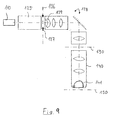
- a projection exposure apparatus 100 for microlithography shown schematically.
- she includes a laser light source 110 whose polarized output light with the help of a lighting system 120 prepared and in a Exit plane 130 of the illumination system is transmitted in the there is a structure-bearing transmission mask (reticle).
- the Pattern of the mask is using a projection lens 140 with high numerical aperture in the image plane 150 of the projection lens in which a photosensitive coated layer Substrate (e.g., semiconductor wafer) is arranged.
- a photosensitive coated layer Substrate e.g., semiconductor wafer
- the lighting system comprises a group 125 optical Facilities that serve in a field level 126 of the Lighting system a homogeneously illuminated lighting field with a defined angular distribution of the incoming radiation be provided, wherein the angular distribution normally to the nature of Structure of the reticle can be adjusted.
- Near the field level 126 sits an adjustable field stop 127 to the sharp edges of the Field.
- An imaging lens 128 following the field plane forms the Field level 126 on the reticle from.
- Meniscus lenses 129 arranged, which has a strongly curved entrance surface and has a comparatively strongly curved exit surface and under other adjustment of the telecentricity of the radiation is used.
- the projection lens 140, the dioptric or catoptric constructed can typically have a picture-side numerical aperture NA ⁇ 0.7.
- NA ⁇ 0.7 the last optical element before the Image plane 150 a plano-convex lens 141 with a flat exit surface and strongly curved, spherical entrance surface provided, which with high Aperture impinging radiation aberration to the image plane 150 merges.
- the meniscus lens 129 of the imaging system 128 and the plano-convex lens 141 of the projection lens 140 are typical examples of Lenses in high-aperture imaging systems that are close to Field levels lie and their transmission properties in terms as far as possible on intensity errors as well as wavefront errors should be even.
- systems for 193 nm operating wavelength are close to field attached lenses commonly made of calcium fluoride to get into these areas high radiation energy density property changes of the optical System due to radiation-induced density changes (especially compaction) to avoid. Therefore, the invention especially in the field of microlithography at working wavelengths deep ultraviolet (DUV) range.
- DUV deep ultraviolet
- the problem presented here can be used with all curved ones
- Substrate surfaces on crystal substrates occur in which different Lattice planes form the substrate surface, wherein after the here shown results the possibly resulting anisotropy is particularly pronounced when at least one place Substrate surface a low indexed crystal direction with the Normal direction of the substrate surface coincides. Therefore, can the effect also occur on substrate surfaces whose curvature weaker than that of the examples shown here.
- the considerations underlying the invention may also useful in coating lenses with small bends and are used by plane plates, which are randomly oriented, have single crystal substrate material. It may, for example, in a series production that surfaces of lenses or Planographic plates are crystallographically different, although the geometry the substrates is identical. In particular, it may happen that one or a few of the optical components comprise a substrate surface have indexed at least one point parallel to low Lattice planes of the crystal material, while others Elements are not or not in the same form the case.
Landscapes
- Physics & Mathematics (AREA)
- General Physics & Mathematics (AREA)
- Optics & Photonics (AREA)
- Chemical & Material Sciences (AREA)
- Inorganic Chemistry (AREA)
- Crystallography & Structural Chemistry (AREA)
- Surface Treatment Of Optical Elements (AREA)
- Exposure And Positioning Against Photoresist Photosensitive Materials (AREA)
- Optical Filters (AREA)
Applications Claiming Priority (2)
| Application Number | Priority Date | Filing Date | Title |
|---|---|---|---|
| US57150204P | 2004-05-17 | 2004-05-17 | |
| US571502P | 2004-05-17 |
Publications (2)
| Publication Number | Publication Date |
|---|---|
| EP1598681A2 true EP1598681A2 (fr) | 2005-11-23 |
| EP1598681A3 EP1598681A3 (fr) | 2006-03-01 |
Family
ID=34935605
Family Applications (1)
| Application Number | Title | Priority Date | Filing Date |
|---|---|---|---|
| EP05008873A Withdrawn EP1598681A3 (fr) | 2004-05-17 | 2005-04-22 | Composant optique ayant une surface courbée et un revêtement multicouche |
Country Status (2)
| Country | Link |
|---|---|
| US (1) | US7489441B2 (fr) |
| EP (1) | EP1598681A3 (fr) |
Families Citing this family (91)
| Publication number | Priority date | Publication date | Assignee | Title |
|---|---|---|---|---|
| JP4804251B2 (ja) * | 2006-07-20 | 2011-11-02 | キヤノン株式会社 | 撮像装置及び撮像ユニット |
| US8847249B2 (en) * | 2008-06-16 | 2014-09-30 | Soraa, Inc. | Solid-state optical device having enhanced indium content in active regions |
| US8143148B1 (en) | 2008-07-14 | 2012-03-27 | Soraa, Inc. | Self-aligned multi-dielectric-layer lift off process for laser diode stripes |
| US8259769B1 (en) | 2008-07-14 | 2012-09-04 | Soraa, Inc. | Integrated total internal reflectors for high-gain laser diodes with high quality cleaved facets on nonpolar/semipolar GaN substrates |
| US8805134B1 (en) | 2012-02-17 | 2014-08-12 | Soraa Laser Diode, Inc. | Methods and apparatus for photonic integration in non-polar and semi-polar oriented wave-guided optical devices |
| CN102144294A (zh) | 2008-08-04 | 2011-08-03 | Soraa有限公司 | 使用非极性或半极性的含镓材料和磷光体的白光器件 |
| US8284810B1 (en) | 2008-08-04 | 2012-10-09 | Soraa, Inc. | Solid state laser device using a selected crystal orientation in non-polar or semi-polar GaN containing materials and methods |
| US8247886B1 (en) | 2009-03-09 | 2012-08-21 | Soraa, Inc. | Polarization direction of optical devices using selected spatial configurations |
| US8422525B1 (en) | 2009-03-28 | 2013-04-16 | Soraa, Inc. | Optical device structure using miscut GaN substrates for laser applications |
| WO2010120819A1 (fr) * | 2009-04-13 | 2010-10-21 | Kaai, Inc. | Structure de dispositif optique mettant en oeuvre des substrats à base de nitrure de gallium pour des applications laser |
| US8294179B1 (en) | 2009-04-17 | 2012-10-23 | Soraa, Inc. | Optical device structure using GaN substrates and growth structures for laser applications |
| US8242522B1 (en) | 2009-05-12 | 2012-08-14 | Soraa, Inc. | Optical device structure using non-polar GaN substrates and growth structures for laser applications in 481 nm |
| US8254425B1 (en) | 2009-04-17 | 2012-08-28 | Soraa, Inc. | Optical device structure using GaN substrates and growth structures for laser applications |
| US8837545B2 (en) | 2009-04-13 | 2014-09-16 | Soraa Laser Diode, Inc. | Optical device structure using GaN substrates and growth structures for laser applications |
| US8634442B1 (en) | 2009-04-13 | 2014-01-21 | Soraa Laser Diode, Inc. | Optical device structure using GaN substrates for laser applications |
| US8416825B1 (en) | 2009-04-17 | 2013-04-09 | Soraa, Inc. | Optical device structure using GaN substrates and growth structure for laser applications |
| US8791499B1 (en) | 2009-05-27 | 2014-07-29 | Soraa, Inc. | GaN containing optical devices and method with ESD stability |
| US9829780B2 (en) | 2009-05-29 | 2017-11-28 | Soraa Laser Diode, Inc. | Laser light source for a vehicle |
| US10108079B2 (en) | 2009-05-29 | 2018-10-23 | Soraa Laser Diode, Inc. | Laser light source for a vehicle |
| US9800017B1 (en) | 2009-05-29 | 2017-10-24 | Soraa Laser Diode, Inc. | Laser device and method for a vehicle |
| US8427590B2 (en) | 2009-05-29 | 2013-04-23 | Soraa, Inc. | Laser based display method and system |
| US9250044B1 (en) | 2009-05-29 | 2016-02-02 | Soraa Laser Diode, Inc. | Gallium and nitrogen containing laser diode dazzling devices and methods of use |
| US8247887B1 (en) * | 2009-05-29 | 2012-08-21 | Soraa, Inc. | Method and surface morphology of non-polar gallium nitride containing substrates |
| US8509275B1 (en) | 2009-05-29 | 2013-08-13 | Soraa, Inc. | Gallium nitride based laser dazzling device and method |
| US20110056429A1 (en) * | 2009-08-21 | 2011-03-10 | Soraa, Inc. | Rapid Growth Method and Structures for Gallium and Nitrogen Containing Ultra-Thin Epitaxial Structures for Devices |
| US9000466B1 (en) | 2010-08-23 | 2015-04-07 | Soraa, Inc. | Methods and devices for light extraction from a group III-nitride volumetric LED using surface and sidewall roughening |
| US8314429B1 (en) | 2009-09-14 | 2012-11-20 | Soraa, Inc. | Multi color active regions for white light emitting diode |
| US8750342B1 (en) | 2011-09-09 | 2014-06-10 | Soraa Laser Diode, Inc. | Laser diodes with scribe structures |
| US8355418B2 (en) | 2009-09-17 | 2013-01-15 | Soraa, Inc. | Growth structures and method for forming laser diodes on {20-21} or off cut gallium and nitrogen containing substrates |
| US9583678B2 (en) | 2009-09-18 | 2017-02-28 | Soraa, Inc. | High-performance LED fabrication |
| US9293644B2 (en) | 2009-09-18 | 2016-03-22 | Soraa, Inc. | Power light emitting diode and method with uniform current density operation |
| KR101368906B1 (ko) | 2009-09-18 | 2014-02-28 | 소라, 인코포레이티드 | 전력 발광 다이오드 및 전류 밀도 작동 방법 |
| US8933644B2 (en) | 2009-09-18 | 2015-01-13 | Soraa, Inc. | LED lamps with improved quality of light |
| US20110186874A1 (en) * | 2010-02-03 | 2011-08-04 | Soraa, Inc. | White Light Apparatus and Method |
| US10147850B1 (en) | 2010-02-03 | 2018-12-04 | Soraa, Inc. | System and method for providing color light sources in proximity to predetermined wavelength conversion structures |
| US20110182056A1 (en) * | 2010-06-23 | 2011-07-28 | Soraa, Inc. | Quantum Dot Wavelength Conversion for Optical Devices Using Nonpolar or Semipolar Gallium Containing Materials |
| US8905588B2 (en) | 2010-02-03 | 2014-12-09 | Sorra, Inc. | System and method for providing color light sources in proximity to predetermined wavelength conversion structures |
| US9927611B2 (en) | 2010-03-29 | 2018-03-27 | Soraa Laser Diode, Inc. | Wearable laser based display method and system |
| US8451876B1 (en) | 2010-05-17 | 2013-05-28 | Soraa, Inc. | Method and system for providing bidirectional light sources with broad spectrum |
| US9450143B2 (en) | 2010-06-18 | 2016-09-20 | Soraa, Inc. | Gallium and nitrogen containing triangular or diamond-shaped configuration for optical devices |
| US8816319B1 (en) | 2010-11-05 | 2014-08-26 | Soraa Laser Diode, Inc. | Method of strain engineering and related optical device using a gallium and nitrogen containing active region |
| US8975615B2 (en) | 2010-11-09 | 2015-03-10 | Soraa Laser Diode, Inc. | Method of fabricating optical devices using laser treatment of contact regions of gallium and nitrogen containing material |
| US9048170B2 (en) | 2010-11-09 | 2015-06-02 | Soraa Laser Diode, Inc. | Method of fabricating optical devices using laser treatment |
| US9595813B2 (en) | 2011-01-24 | 2017-03-14 | Soraa Laser Diode, Inc. | Laser package having multiple emitters configured on a substrate member |
| US9318875B1 (en) | 2011-01-24 | 2016-04-19 | Soraa Laser Diode, Inc. | Color converting element for laser diode |
| US8786053B2 (en) | 2011-01-24 | 2014-07-22 | Soraa, Inc. | Gallium-nitride-on-handle substrate materials and devices and method of manufacture |
| US9025635B2 (en) | 2011-01-24 | 2015-05-05 | Soraa Laser Diode, Inc. | Laser package having multiple emitters configured on a support member |
| US9093820B1 (en) | 2011-01-25 | 2015-07-28 | Soraa Laser Diode, Inc. | Method and structure for laser devices using optical blocking regions |
| US9287684B2 (en) | 2011-04-04 | 2016-03-15 | Soraa Laser Diode, Inc. | Laser package having multiple emitters with color wheel |
| US8686431B2 (en) | 2011-08-22 | 2014-04-01 | Soraa, Inc. | Gallium and nitrogen containing trilateral configuration for optical devices |
| US8971370B1 (en) | 2011-10-13 | 2015-03-03 | Soraa Laser Diode, Inc. | Laser devices using a semipolar plane |
| US8912025B2 (en) | 2011-11-23 | 2014-12-16 | Soraa, Inc. | Method for manufacture of bright GaN LEDs using a selective removal process |
| CN104247052B (zh) | 2012-03-06 | 2017-05-03 | 天空公司 | 具有减少导光效果的低折射率材料层的发光二极管 |
| US9020003B1 (en) | 2012-03-14 | 2015-04-28 | Soraa Laser Diode, Inc. | Group III-nitride laser diode grown on a semi-polar orientation of gallium and nitrogen containing substrates |
| US9800016B1 (en) | 2012-04-05 | 2017-10-24 | Soraa Laser Diode, Inc. | Facet on a gallium and nitrogen containing laser diode |
| US10559939B1 (en) | 2012-04-05 | 2020-02-11 | Soraa Laser Diode, Inc. | Facet on a gallium and nitrogen containing laser diode |
| US9343871B1 (en) | 2012-04-05 | 2016-05-17 | Soraa Laser Diode, Inc. | Facet on a gallium and nitrogen containing laser diode |
| US9088135B1 (en) | 2012-06-29 | 2015-07-21 | Soraa Laser Diode, Inc. | Narrow sized laser diode |
| US9184563B1 (en) | 2012-08-30 | 2015-11-10 | Soraa Laser Diode, Inc. | Laser diodes with an etched facet and surface treatment |
| US9978904B2 (en) | 2012-10-16 | 2018-05-22 | Soraa, Inc. | Indium gallium nitride light emitting devices |
| US8802471B1 (en) | 2012-12-21 | 2014-08-12 | Soraa, Inc. | Contacts for an n-type gallium and nitrogen substrate for optical devices |
| US9166372B1 (en) | 2013-06-28 | 2015-10-20 | Soraa Laser Diode, Inc. | Gallium nitride containing laser device configured on a patterned substrate |
| US8994033B2 (en) | 2013-07-09 | 2015-03-31 | Soraa, Inc. | Contacts for an n-type gallium and nitrogen substrate for optical devices |
| US9368939B2 (en) | 2013-10-18 | 2016-06-14 | Soraa Laser Diode, Inc. | Manufacturable laser diode formed on C-plane gallium and nitrogen material |
| US9362715B2 (en) | 2014-02-10 | 2016-06-07 | Soraa Laser Diode, Inc | Method for manufacturing gallium and nitrogen bearing laser devices with improved usage of substrate material |
| US9379525B2 (en) | 2014-02-10 | 2016-06-28 | Soraa Laser Diode, Inc. | Manufacturable laser diode |
| US9520695B2 (en) | 2013-10-18 | 2016-12-13 | Soraa Laser Diode, Inc. | Gallium and nitrogen containing laser device having confinement region |
| US9419189B1 (en) | 2013-11-04 | 2016-08-16 | Soraa, Inc. | Small LED source with high brightness and high efficiency |
| US9209596B1 (en) | 2014-02-07 | 2015-12-08 | Soraa Laser Diode, Inc. | Manufacturing a laser diode device from a plurality of gallium and nitrogen containing substrates |
| US9871350B2 (en) | 2014-02-10 | 2018-01-16 | Soraa Laser Diode, Inc. | Manufacturable RGB laser diode source |
| US9520697B2 (en) | 2014-02-10 | 2016-12-13 | Soraa Laser Diode, Inc. | Manufacturable multi-emitter laser diode |
| US9564736B1 (en) | 2014-06-26 | 2017-02-07 | Soraa Laser Diode, Inc. | Epitaxial growth of p-type cladding regions using nitrogen gas for a gallium and nitrogen containing laser diode |
| US9246311B1 (en) | 2014-11-06 | 2016-01-26 | Soraa Laser Diode, Inc. | Method of manufacture for an ultraviolet laser diode |
| US9666677B1 (en) | 2014-12-23 | 2017-05-30 | Soraa Laser Diode, Inc. | Manufacturable thin film gallium and nitrogen containing devices |
| US9653642B1 (en) | 2014-12-23 | 2017-05-16 | Soraa Laser Diode, Inc. | Manufacturable RGB display based on thin film gallium and nitrogen containing light emitting diodes |
| DE102015100091A1 (de) * | 2015-01-07 | 2016-07-07 | Rodenstock Gmbh | Schichtsystem und optisches Element mit einem Schichtsystem |
| US10879673B2 (en) | 2015-08-19 | 2020-12-29 | Soraa Laser Diode, Inc. | Integrated white light source using a laser diode and a phosphor in a surface mount device package |
| US11437774B2 (en) | 2015-08-19 | 2022-09-06 | Kyocera Sld Laser, Inc. | High-luminous flux laser-based white light source |
| US10938182B2 (en) | 2015-08-19 | 2021-03-02 | Soraa Laser Diode, Inc. | Specialized integrated light source using a laser diode |
| US11437775B2 (en) | 2015-08-19 | 2022-09-06 | Kyocera Sld Laser, Inc. | Integrated light source using a laser diode |
| US20170066684A1 (en) | 2015-09-08 | 2017-03-09 | Corning Incorporated | Optical coatings including buffer layers |
| US9787963B2 (en) | 2015-10-08 | 2017-10-10 | Soraa Laser Diode, Inc. | Laser lighting having selective resolution |
| US10771155B2 (en) | 2017-09-28 | 2020-09-08 | Soraa Laser Diode, Inc. | Intelligent visible light with a gallium and nitrogen containing laser source |
| US10222474B1 (en) | 2017-12-13 | 2019-03-05 | Soraa Laser Diode, Inc. | Lidar systems including a gallium and nitrogen containing laser light source |
| US10551728B1 (en) | 2018-04-10 | 2020-02-04 | Soraa Laser Diode, Inc. | Structured phosphors for dynamic lighting |
| US11421843B2 (en) | 2018-12-21 | 2022-08-23 | Kyocera Sld Laser, Inc. | Fiber-delivered laser-induced dynamic light system |
| US11239637B2 (en) | 2018-12-21 | 2022-02-01 | Kyocera Sld Laser, Inc. | Fiber delivered laser induced white light system |
| US12000552B2 (en) | 2019-01-18 | 2024-06-04 | Kyocera Sld Laser, Inc. | Laser-based fiber-coupled white light system for a vehicle |
| US11884202B2 (en) | 2019-01-18 | 2024-01-30 | Kyocera Sld Laser, Inc. | Laser-based fiber-coupled white light system |
| US11228158B2 (en) | 2019-05-14 | 2022-01-18 | Kyocera Sld Laser, Inc. | Manufacturable laser diodes on a large area gallium and nitrogen containing substrate |
| US10903623B2 (en) | 2019-05-14 | 2021-01-26 | Soraa Laser Diode, Inc. | Method and structure for manufacturable large area gallium and nitrogen containing substrate |
Citations (2)
| Publication number | Priority date | Publication date | Assignee | Title |
|---|---|---|---|---|
| US20020035024A1 (en) * | 2000-07-27 | 2002-03-21 | Hideo Kato | Optical, additional films and optical elements |
| US20030021015A1 (en) * | 2000-04-07 | 2003-01-30 | Maier Robert L. | Film coated optical lithography elements and method of making |
Family Cites Families (12)
| Publication number | Priority date | Publication date | Assignee | Title |
|---|---|---|---|---|
| US6261696B1 (en) | 1996-03-22 | 2001-07-17 | Canon Kabushika Kaisha | Optical element with substrate containing fluorite as main ingredient, and method and apparatus for producing the optical element |
| JP3924806B2 (ja) | 1996-06-10 | 2007-06-06 | 株式会社ニコン | 反射防止膜 |
| DE19830449A1 (de) * | 1998-07-08 | 2000-01-27 | Zeiss Carl Fa | SiO¶2¶-beschichtetes Spiegelsubstrat für EUV |
| US6683714B1 (en) * | 1999-06-25 | 2004-01-27 | Corning Incorporated | Birefringence minimizing fluoride crystal optical VUV microlithography lens elements and optical blanks |
| EP1224497A4 (fr) * | 1999-06-25 | 2003-08-27 | Corning Inc | Lentille optique pour microlithographie vuv a cristaux de fluorure qui minimise l'effet birefringent, et paraisons optiques de celle-ci |
| DE10148308A1 (de) | 2001-02-23 | 2002-09-26 | Zeiss Carl | Beleuchtungssystem mit reduzierter energetischer Belastung |
| US6683728B2 (en) | 2001-03-20 | 2004-01-27 | Carl-Zeiss-Stiftung | Illumination system with reduced energy loading |
| EP1390783A2 (fr) | 2001-05-15 | 2004-02-25 | Carl Zeiss | Objectif comportant des lentilles de cristal de fluorure |
| JP2004531764A (ja) * | 2001-05-16 | 2004-10-14 | コーニング インコーポレイテッド | 好ましい結晶方位をもつ立方晶系結晶材料光学素子 |
| WO2003009015A1 (fr) | 2001-07-18 | 2003-01-30 | Nikon Corporation | Element optique comportant un film de fluorure de lanthane |
| US20040218271A1 (en) * | 2001-07-18 | 2004-11-04 | Carl Zeiss Smt Ag | Retardation element made from cubic crystal and an optical system therewith |
| US6958864B2 (en) * | 2002-08-22 | 2005-10-25 | Asml Netherlands B.V. | Structures and methods for reducing polarization aberration in integrated circuit fabrication systems |
-
2005
- 2005-04-22 EP EP05008873A patent/EP1598681A3/fr not_active Withdrawn
- 2005-05-17 US US11/130,173 patent/US7489441B2/en not_active Expired - Fee Related
Patent Citations (2)
| Publication number | Priority date | Publication date | Assignee | Title |
|---|---|---|---|---|
| US20030021015A1 (en) * | 2000-04-07 | 2003-01-30 | Maier Robert L. | Film coated optical lithography elements and method of making |
| US20020035024A1 (en) * | 2000-07-27 | 2002-03-21 | Hideo Kato | Optical, additional films and optical elements |
Also Published As
| Publication number | Publication date |
|---|---|
| EP1598681A3 (fr) | 2006-03-01 |
| US7489441B2 (en) | 2009-02-10 |
| US20050286827A1 (en) | 2005-12-29 |
Similar Documents
| Publication | Publication Date | Title |
|---|---|---|
| EP1598681A2 (fr) | Composant optique ayant une surface courbée et un revêtement multicouche | |
| EP1260835B1 (fr) | Filtre pour l'atténuation de rayons ultraviolets | |
| WO2005059653A2 (fr) | Dispositif de temporisation ayant un effet optique de polarisation et dispositif d'eclairage de projection microlithographique comportant un tel dispositif de temporisation | |
| EP1390783A2 (fr) | Objectif comportant des lentilles de cristal de fluorure | |
| DE102008040613A1 (de) | Optisches System einer mikrolithographischen Projektionsbelichtungsanlage | |
| EP0937999A1 (fr) | Système optique avec compensateur de polarisation | |
| DE10123725A1 (de) | Projektionsbelichtungsanlage der Mikrolithographie, Optisches System und Herstellverfahren | |
| DE102004059778A1 (de) | Projektionsobjektiv für Immersions-Lithografie | |
| DE102005030543A1 (de) | Polarisatoreinrichtung zur Erzeugung einer definierten Ortsverteilung von Polarisationszuständen | |
| DE102007054731A1 (de) | Optisches Element zur Reflexion von UV-Strahlung, Herstellungsverfahren dafür und Projektionsbelichtungsanlage damit | |
| EP1215512A2 (fr) | Revêtement anti-réfléchissant pour lumière ultraviolette à grands angles d'incidence | |
| DE10210782A1 (de) | Objektiv mit Kristall-Linsen | |
| WO2006053705A1 (fr) | Procede pour proteger un miroir metallique contre la degradation et miroir metallique | |
| DE102010041502A1 (de) | Spiegel, Projektionsobjektiv mit einem solchen Spiegel und Projektionsbelichtungs-anlage für die Mikrolithographie mit einem solchen Projektionsobjektiv | |
| EP3030936B1 (fr) | Miroir pour appareil d'exposition par projection microlithographique | |
| DE10322376A1 (de) | Axiconsystem und Beleuchtungssystem damit | |
| EP1407299A1 (fr) | Element de retard en cristal cubique et systemes optiques comportant un tel element | |
| DE102011054837A1 (de) | Optisches Element | |
| DE102005041938A1 (de) | Mikrolithographische Projektionsbelichtungsanlage | |
| DE102013200294A1 (de) | EUV-Spiegel und optisches System mit EUV-Spiegel | |
| DE10139188A1 (de) | Glaskeramik für röntgenoptische Komponenten | |
| WO2004001480A2 (fr) | Objectif de reduction catadioptrique | |
| DE10127320A1 (de) | Objektiv mit Fluorid-Kristall-Linsen | |
| WO2003096124A1 (fr) | Lentille en matiere cristalline | |
| EP1726994A2 (fr) | Intégrateur de lumière pour un système d'éclairage, en particulier pour une installation d'éclairage de projection microlithographique |
Legal Events
| Date | Code | Title | Description |
|---|---|---|---|
| PUAI | Public reference made under article 153(3) epc to a published international application that has entered the european phase |
Free format text: ORIGINAL CODE: 0009012 |
|
| AK | Designated contracting states |
Kind code of ref document: A2 Designated state(s): AT BE BG CH CY CZ DE DK EE ES FI FR GB GR HU IE IS IT LI LT LU MC NL PL PT RO SE SI SK TR |
|
| AX | Request for extension of the european patent |
Extension state: AL BA HR LV MK YU |
|
| PUAL | Search report despatched |
Free format text: ORIGINAL CODE: 0009013 |
|
| AK | Designated contracting states |
Kind code of ref document: A3 Designated state(s): AT BE BG CH CY CZ DE DK EE ES FI FR GB GR HU IE IS IT LI LT LU MC NL PL PT RO SE SI SK TR |
|
| AX | Request for extension of the european patent |
Extension state: AL BA HR LV MK YU |
|
| 17P | Request for examination filed |
Effective date: 20060315 |
|
| AKX | Designation fees paid |
Designated state(s): DE FR GB NL |
|
| RAP1 | Party data changed (applicant data changed or rights of an application transferred) |
Owner name: CARL ZEISS SMT AG |
|
| 17Q | First examination report despatched |
Effective date: 20090803 |
|
| STAA | Information on the status of an ep patent application or granted ep patent |
Free format text: STATUS: THE APPLICATION IS DEEMED TO BE WITHDRAWN |
|
| 18D | Application deemed to be withdrawn |
Effective date: 20091215 |