EP1598521A1 - Turbocompresseur pour gaz d'échappement - Google Patents
Turbocompresseur pour gaz d'échappement Download PDFInfo
- Publication number
- EP1598521A1 EP1598521A1 EP05009768A EP05009768A EP1598521A1 EP 1598521 A1 EP1598521 A1 EP 1598521A1 EP 05009768 A EP05009768 A EP 05009768A EP 05009768 A EP05009768 A EP 05009768A EP 1598521 A1 EP1598521 A1 EP 1598521A1
- Authority
- EP
- European Patent Office
- Prior art keywords
- shaft
- exhaust gas
- gas turbocharger
- housing
- turbine
- Prior art date
- Legal status (The legal status is an assumption and is not a legal conclusion. Google has not performed a legal analysis and makes no representation as to the accuracy of the status listed.)
- Withdrawn
Links
Images
Classifications
-
- F—MECHANICAL ENGINEERING; LIGHTING; HEATING; WEAPONS; BLASTING
- F01—MACHINES OR ENGINES IN GENERAL; ENGINE PLANTS IN GENERAL; STEAM ENGINES
- F01D—NON-POSITIVE DISPLACEMENT MACHINES OR ENGINES, e.g. STEAM TURBINES
- F01D25/00—Component parts, details, or accessories, not provided for in, or of interest apart from, other groups
- F01D25/08—Cooling; Heating; Heat-insulation
- F01D25/14—Casings modified therefor
- F01D25/145—Thermally insulated casings
-
- F—MECHANICAL ENGINEERING; LIGHTING; HEATING; WEAPONS; BLASTING
- F01—MACHINES OR ENGINES IN GENERAL; ENGINE PLANTS IN GENERAL; STEAM ENGINES
- F01D—NON-POSITIVE DISPLACEMENT MACHINES OR ENGINES, e.g. STEAM TURBINES
- F01D25/00—Component parts, details, or accessories, not provided for in, or of interest apart from, other groups
- F01D25/24—Casings; Casing parts, e.g. diaphragms, casing fastenings
- F01D25/243—Flange connections; Bolting arrangements
-
- F—MECHANICAL ENGINEERING; LIGHTING; HEATING; WEAPONS; BLASTING
- F05—INDEXING SCHEMES RELATING TO ENGINES OR PUMPS IN VARIOUS SUBCLASSES OF CLASSES F01-F04
- F05D—INDEXING SCHEME FOR ASPECTS RELATING TO NON-POSITIVE-DISPLACEMENT MACHINES OR ENGINES, GAS-TURBINES OR JET-PROPULSION PLANTS
- F05D2220/00—Application
- F05D2220/40—Application in turbochargers
-
- F—MECHANICAL ENGINEERING; LIGHTING; HEATING; WEAPONS; BLASTING
- F05—INDEXING SCHEMES RELATING TO ENGINES OR PUMPS IN VARIOUS SUBCLASSES OF CLASSES F01-F04
- F05D—INDEXING SCHEME FOR ASPECTS RELATING TO NON-POSITIVE-DISPLACEMENT MACHINES OR ENGINES, GAS-TURBINES OR JET-PROPULSION PLANTS
- F05D2300/00—Materials; Properties thereof
- F05D2300/50—Intrinsic material properties or characteristics
- F05D2300/502—Thermal properties
- F05D2300/5024—Heat conductivity
Definitions
- the invention relates to an exhaust gas turbocharger with a Shaft, which is a turbine wheel arranged in a turbine housing and a compressor wheel connects, and with a interposed storage with a bearing housing and bearings disposed therein for the shaft.
- Exhaust gas turbochargers are used to improve the efficiency and thus the increase in performance of combustion engines. You have a wave on one end with a Turbine and the other end provided with a compressor wheel is. The turbine wheel is powered by exhaust gas from the combustion engine acted essentially the thermal energy of the exhaust gas through the turbine wheel in a rotational movement is implemented. that's going to be over the wave Compressor wheel driven, the fresh air sucks and with Overpressure to flow into the intake ports of the engine leaves and thus improves the degree of filling.
- the wave reaches high speeds of up to 300,000 rpm.
- the turbocharger on the turbine side through the Exhaust gas flow exposed to high temperatures in gasoline engines can reach more than 1,000 ° C while the Temperature on the compressor side generally not reached more than 150 ° C. It is understood that thereby an enormous thermal load of the bearings arises, which are adjacent to the turbine side.
- the invention is therefore based on the object, an exhaust gas turbocharger of the type mentioned above in such a way that with cost-effective measures, a warming of the bearings to temperatures that affect their operational safety, is avoided.
- the shaft between turbine wheel and bearing at least has a thermal insulation whose thermal permeability less than that adjacent to the thermal insulation Areas of the shaft and the heat transfer hampered by the wave. This is based on the knowledge that an essential part of the turbine side resulting heat transferred via the shaft in the storage becomes. Due to the heat insulation, the heat transfer reduced to storage, with the measure the reduction by appropriate training of thermal insulation and by dimensioning them to the respective ones Requirements can be adjusted.
- the thermal insulation one over the cross section of the wave going Insulating layer having a lower thermal conductivity otherwise than the material of the shaft.
- the insulating layer must be such that on the one hand resistant to the temperatures encountered on the other hand, the wave is not or not is greatly weakened.
- they are particularly suitable Metals whose thermal conductivity is lower, especially considerably less than the material, from which the wave exists otherwise, namely in the Usually steel.
- metals come for the insulating layer especially nickel-chromium alloys in question as they are under but the brands INCONEL® or INCOLOY® are known also stainless steel alloys.
- the heat insulation can also have an area where the cross-sectional area of the shaft is reduced and on this way the heat transfer is hindered.
- This can For example, done by that in the shaft Cavity is formed, wherein the cavity also can extend over the entire length of the shaft, so a hollow shaft is present.
- the object underlying the invention may alternatively to or in combination with the aforementioned measures be solved in that the shaft between the turbine wheel and storage and / or the bearing housing additional Have or have heat transfer surfaces. These additional heat transfer surfaces improve the heat dissipation to the environment.
- the heat transfer surfaces can for example, as at least one sitting on the shaft Cooling disk be formed.
- the object underlying the invention may alternatively to or in combination with the above measures also be solved in that the flanges, on the Bearing housing and turbine housing coupled together are, have a thermal insulation whose thermal permeability less than that of the flanges themselves This way, the heat conduction through the housing caused heat transfer can be reduced.
- the insulating layer can - as in the thermal insulation the wave - made of a metal, for example a nickel-chromium alloy or a stainless steel alloy, consist.
- a metal for example a nickel-chromium alloy or a stainless steel alloy, consist.
- others, too, can be bad thermally conductive materials, in particular mineral or ceramic materials, be used.
- an insulating layer can have the thermal insulation insulating webs over which the Flanges of the flange are adjacent to each other.
- the idea is based on the surfaces over which the two flanges together, as small as possible hold. It is possible, the Isolierstege form so that they include a cavity, the can be filled with an insulating material.
- the turbine housing and / or the bearing housing on the outside at least partially with a coating is or are the heat dissipation to the environment improved. Also this measure can with the The measures described above are combined to To improve protection against thermal stress of the bearings.
- the coating can have better thermal conductivity have as the material of the turbine housing or of the bearing housing. So can the surface by flame spraying be provided with aluminum. Alternatively or In combination, the coating should also be a higher one Heat emissivities have as the material of the turbine housing or bearing housing.
- the turbine housing on his Inner side at least partially with a coating too provided, which reduces the heat absorption of the turbine housing.
- the coating should have a lower heat absorption capacity have as the material of the turbine housing. In this way, the heat absorption of the housing reduced.
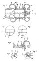
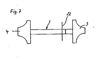
- the turbocharger 1 shown in Figure 1 has a typical Construction. He has a wave 2, on the right side a turbine wheel 3 and on the left a compressor 4 to sit.
- the shaft 2 is not shown here bearing stored in a tubular bearing housing 5. Camps can be designed as a magnetic bearing, as this For example, in DE 102 16 447 C1 discloses.
- the turbine wheel 3 is surrounded by a turbine housing 6, the one not shown here radial inlet port Has.
- the compressor 4 is of a compressor housing 9 surrounded, with a central inlet opening 10 is provided. About this inlet opening 10 is sucked 4 air due to the rotational movement of the compressor wheel and deflected into an annular space 11. This condensed Air then leaves the annulus 11 via a here Aulschreibö réelle not shown in the direction of Inlet side of the internal combustion engine.
- the turbine housing 6 and the compressor housing 9 are with the bearing housing 5 via two flanges 12, 13th or 14, 15 connected.
- the flanges 12, 13 and 14, 15 are over here not shown screws in usual Way braced with each other.
- Figure 2 shows a wave detail adjacent to the turbine housing 6 or to the turbine wheel 3.
- a Intermediate piece 16 welded, made of a nickel-chromium alloy exists and therefore much worse directs than the otherwise made of a steel shaft 2.
- the intermediate piece 16 acts as an insulating layer and obstructed the heat transfer in the direction of the turbine wheel 3 and thus the bearing in the bearing housing. 5
- FIG. 3 shows another embodiment of a wave detail, which is arranged in the same place.
- the wave 2 is here provided with a cavity 17, which for the Heat conduction available cross-sectional area the shaft 2 reduced to an outer ring area and This hinders the heat transfer.
- Figure 4 shows the upper part of the bearing housing 5 and the adjacent turbine housing 6 without shaft 2 and without Turbine wheel 3.
- Figure 5 is a variant the flange connection between the bearing housing. 5 and the turbine housing 6.
- an insulating layer 18 is arranged, the heat transfer from the turbine housing. 6 reduced to the bearing housing 5.
- the heat transfer between the flanges 12, 13 can but also be hampered by the fact that the mutual Installation of the flanges 12, 13 takes place only via webs 19, 20, as can be seen in the detail of Figure 6.
- the Webs 19, 20 extend annularly over the entire Circumference of the flanges 12, 13 and therefore close one Cavity 21 a.
- the small cross-sectional area of the webs 19, 20 obstructs the heat conduction from the turbine housing 6 belonging flange 12 on the bearing housing 5 belonging Flange 13.
- the turbine housing 6 on an outer side be provided with a coating that the heat transfer improved to the environment, so a better thermal conductivity and / or a higher heat emissivity has as the material from which the turbine housing. 6 consists.
- the turbine housing 6 on his Inner side with a heat absorption reducing coating be provided.
Landscapes
- Engineering & Computer Science (AREA)
- Mechanical Engineering (AREA)
- General Engineering & Computer Science (AREA)
- Supercharger (AREA)
Priority Applications (1)
| Application Number | Priority Date | Filing Date | Title |
|---|---|---|---|
| EP07000729A EP1795711A2 (fr) | 2004-05-18 | 2005-05-04 | Turbocompresseur à gaz d'échappement |
Applications Claiming Priority (2)
| Application Number | Priority Date | Filing Date | Title |
|---|---|---|---|
| DE102004025049 | 2004-05-18 | ||
| DE102004025049A DE102004025049A1 (de) | 2004-05-18 | 2004-05-18 | Abgasturbolader |
Related Child Applications (1)
| Application Number | Title | Priority Date | Filing Date |
|---|---|---|---|
| EP07000729A Division EP1795711A2 (fr) | 2004-05-18 | 2005-05-04 | Turbocompresseur à gaz d'échappement |
Publications (1)
| Publication Number | Publication Date |
|---|---|
| EP1598521A1 true EP1598521A1 (fr) | 2005-11-23 |
Family
ID=34936133
Family Applications (2)
| Application Number | Title | Priority Date | Filing Date |
|---|---|---|---|
| EP07000729A Withdrawn EP1795711A2 (fr) | 2004-05-18 | 2005-05-04 | Turbocompresseur à gaz d'échappement |
| EP05009768A Withdrawn EP1598521A1 (fr) | 2004-05-18 | 2005-05-04 | Turbocompresseur pour gaz d'échappement |
Family Applications Before (1)
| Application Number | Title | Priority Date | Filing Date |
|---|---|---|---|
| EP07000729A Withdrawn EP1795711A2 (fr) | 2004-05-18 | 2005-05-04 | Turbocompresseur à gaz d'échappement |
Country Status (4)
| Country | Link |
|---|---|
| US (2) | US20050257522A1 (fr) |
| EP (2) | EP1795711A2 (fr) |
| JP (1) | JP2005330968A (fr) |
| DE (1) | DE102004025049A1 (fr) |
Cited By (1)
| Publication number | Priority date | Publication date | Assignee | Title |
|---|---|---|---|---|
| CN103850727A (zh) * | 2012-11-28 | 2014-06-11 | 霍尼韦尔国际公司 | 涡轮增压器的抽吸密封 |
Families Citing this family (26)
| Publication number | Priority date | Publication date | Assignee | Title |
|---|---|---|---|---|
| JP2008202544A (ja) * | 2007-02-21 | 2008-09-04 | Mitsubishi Heavy Ind Ltd | ロータの製造方法及びこのロータをそなえた排気ターボ過給機 |
| DE102008038007A1 (de) | 2008-08-16 | 2010-02-18 | Bosch Mahle Turbo Systems Gmbh & Co. Kg | Abgasturbolader |
| DE102008058507A1 (de) * | 2008-11-21 | 2010-05-27 | Bosch Mahle Turbo Systems Gmbh & Co. Kg | Ladeeinrichtung |
| DE102008058506A1 (de) * | 2008-11-21 | 2010-05-27 | Bosch Mahle Turbo Systems Gmbh & Co. Kg | Ladeeinrichtung |
| DE102009014005A1 (de) * | 2009-03-19 | 2010-09-23 | Bosch Mahle Turbo Systems Gmbh & Co. Kg | Rotierende Strömungsmaschine |
| JP5843757B2 (ja) * | 2009-05-19 | 2016-01-13 | ボーグワーナー インコーポレーテッド | ターボチャージャ |
| DE102009023891A1 (de) * | 2009-06-04 | 2011-03-31 | Continental Automotive Gmbh | Magnetgelagerte Rotorwelle für Abgasturbolader |
| DE102009058411A1 (de) * | 2009-12-16 | 2011-06-22 | BorgWarner Inc., Mich. | Abgasturbolader |
| DE102010011486A1 (de) | 2010-03-16 | 2011-09-22 | Bosch Mahle Turbo Systems Gmbh & Co. Kg | Rotor für eine Ladeeinrichtung |
| US20110280716A1 (en) * | 2010-05-17 | 2011-11-17 | Douglas Gerard Konitzer | Gas turbine engine compressor components comprising thermal barriers, thermal barrier systems, and methods of using the same |
| DE102010050913A1 (de) | 2010-11-11 | 2012-05-16 | Pierburg Gmbh | Abgasturbolader |
| KR101889358B1 (ko) * | 2011-05-10 | 2018-08-17 | 보르그워너 인코퍼레이티드 | 배기가스 터보차저 |
| ES2470322T3 (es) * | 2011-11-09 | 2014-06-23 | Isolite Gmbh | Carcasa de turbina en varias partes para un turbocargador |
| JP6111260B2 (ja) * | 2011-11-23 | 2017-04-05 | ボーグワーナー インコーポレーテッド | 排気ガスターボチャージャ |
| DE112012004531T5 (de) * | 2011-12-09 | 2014-08-07 | Borgwarner Inc. | Lagergehäuse eines Abgasturboladers |
| CN104204538B (zh) * | 2012-03-27 | 2018-05-22 | 博格华纳公司 | 用于保护涡轮增压器铝轴承壳体的系统和方法 |
| TWM446226U (zh) * | 2012-09-04 | 2013-02-01 | Tan Xin Technology Dev Inc | 渦輪增壓器之殼體 |
| DE102014201732B4 (de) | 2013-02-28 | 2024-03-28 | Ford Global Technologies, Llc | Brennkraftmaschine mit flüssigkeitsgekühlter Turbine |
| DE102013111562A1 (de) * | 2013-10-21 | 2015-04-23 | Ihi Charging Systems International Gmbh | Abgasturbolader |
| DE102014201411A1 (de) * | 2014-01-27 | 2015-08-13 | Ford Global Technologies, Llc | Brennkraftmaschine mit gekühlter Turbine |
| US10041400B2 (en) * | 2016-05-20 | 2018-08-07 | Borgwarner Inc. | Hollow filled turbocharger rotor shaft |
| US10690136B2 (en) | 2016-11-04 | 2020-06-23 | Ford Global Technologies, Llc | Supercharged internal combustion engine with compressor |
| DE102016221639B4 (de) * | 2016-11-04 | 2021-11-25 | Ford Global Technologies, Llc | Aufgeladene Brennkraftmaschine mit gekühltem Verdichter |
| US10487741B2 (en) * | 2018-02-27 | 2019-11-26 | GM Global Technology Operations LLC | Turbo vane and compressor for turbocharger |
| JP7490508B2 (ja) * | 2020-09-09 | 2024-05-27 | 日本電子株式会社 | 三次元積層造形装置 |
| CN118043559A (zh) * | 2021-10-01 | 2024-05-14 | 克里奥斯塔股份有限公司 | 用于低温涡轮机的整体式轴、低温涡轮机和制造方法 |
Citations (3)
| Publication number | Priority date | Publication date | Assignee | Title |
|---|---|---|---|---|
| US4557704A (en) * | 1983-11-08 | 1985-12-10 | Ngk Spark Plug Co., Ltd. | Junction structure of turbine shaft |
| US5129784A (en) * | 1990-08-23 | 1992-07-14 | Ngk Spark Plug Co., Ltd. | Ceramic rotor and metal shaft assembly |
| US5174733A (en) * | 1990-08-22 | 1992-12-29 | Ngk Spark Plug Co., Ltd. | Supercharger |
Family Cites Families (13)
| Publication number | Priority date | Publication date | Assignee | Title |
|---|---|---|---|---|
| US2008414A (en) * | 1931-12-04 | 1935-07-16 | Eugene H Fischer | Insulator |
| US4083180A (en) * | 1976-10-01 | 1978-04-11 | Caterpillar Tractor Co. | Gas turbine engine internal insulation |
| DE2829150A1 (de) * | 1978-07-03 | 1980-01-24 | Barmag Barmer Maschf | Abgasturbolader |
| JPS5939930A (ja) * | 1982-08-27 | 1984-03-05 | Nissan Motor Co Ltd | タ−ボチヤ−ジヤ |
| JPS5949323A (ja) * | 1982-09-10 | 1984-03-21 | Toyota Central Res & Dev Lab Inc | タ−ボ機械 |
| DE3413388A1 (de) * | 1984-04-10 | 1985-10-24 | Aktiengesellschaft Kühnle, Kopp & Kausch, 6710 Frankenthal | Abgasturbolader |
| JPS60226464A (ja) * | 1984-04-20 | 1985-11-11 | 日本特殊陶業株式会社 | セラミックと金属との接合構造 |
| JPH0352987Y2 (fr) * | 1984-10-04 | 1991-11-19 | ||
| JPS6267237A (ja) * | 1985-09-18 | 1987-03-26 | Hitachi Ltd | 二流路型排気駆動タ−ボチヤ−ジヤ |
| US4907952A (en) * | 1986-12-05 | 1990-03-13 | Honda Giken Kogyo Kabushiki Kaisha | Turbocharger |
| DD255369A1 (de) * | 1986-12-22 | 1988-03-30 | Bannewitz Kompressorenbau | Waermedaemmung fuer lager eines abgasturboladers mit ungekuehlten gehaeusen |
| JPH05155668A (ja) * | 1991-12-09 | 1993-06-22 | Ngk Spark Plug Co Ltd | セラミックスと金属との結合体 |
| DE19931150A1 (de) * | 1999-07-06 | 2001-01-11 | Volkswagen Ag | Abgasturbolader |
-
2004
- 2004-05-18 DE DE102004025049A patent/DE102004025049A1/de not_active Withdrawn
-
2005
- 2005-05-04 EP EP07000729A patent/EP1795711A2/fr not_active Withdrawn
- 2005-05-04 EP EP05009768A patent/EP1598521A1/fr not_active Withdrawn
- 2005-05-17 US US11/130,158 patent/US20050257522A1/en not_active Abandoned
- 2005-05-18 JP JP2005145171A patent/JP2005330968A/ja not_active Withdrawn
-
2007
- 2007-01-12 US US11/652,572 patent/US20070113552A1/en not_active Abandoned
Patent Citations (3)
| Publication number | Priority date | Publication date | Assignee | Title |
|---|---|---|---|---|
| US4557704A (en) * | 1983-11-08 | 1985-12-10 | Ngk Spark Plug Co., Ltd. | Junction structure of turbine shaft |
| US5174733A (en) * | 1990-08-22 | 1992-12-29 | Ngk Spark Plug Co., Ltd. | Supercharger |
| US5129784A (en) * | 1990-08-23 | 1992-07-14 | Ngk Spark Plug Co., Ltd. | Ceramic rotor and metal shaft assembly |
Cited By (2)
| Publication number | Priority date | Publication date | Assignee | Title |
|---|---|---|---|---|
| CN103850727A (zh) * | 2012-11-28 | 2014-06-11 | 霍尼韦尔国际公司 | 涡轮增压器的抽吸密封 |
| CN103850727B (zh) * | 2012-11-28 | 2017-08-01 | 霍尼韦尔国际公司 | 涡轮增压器的抽吸密封 |
Also Published As
| Publication number | Publication date |
|---|---|
| EP1795711A2 (fr) | 2007-06-13 |
| US20050257522A1 (en) | 2005-11-24 |
| DE102004025049A1 (de) | 2005-12-15 |
| JP2005330968A (ja) | 2005-12-02 |
| US20070113552A1 (en) | 2007-05-24 |
Similar Documents
| Publication | Publication Date | Title |
|---|---|---|
| EP1598521A1 (fr) | Turbocompresseur pour gaz d'échappement | |
| DE10028160C2 (de) | Gehäusegruppe für die Turbine eines Abgas-Turboladers | |
| EP2499378B1 (fr) | Carter de turbocompresseur | |
| DE3631130C2 (fr) | ||
| EP0136741B1 (fr) | Piston pour moteurs à combustion interne | |
| DE19804232C2 (de) | Brennkammer für Hochleistungstriebwerke und Düsen | |
| DE102009040196A1 (de) | Abgasturbolader für einen Verbrennungsmotor | |
| DE2829150A1 (de) | Abgasturbolader | |
| DE102019104499B4 (de) | Turbine und Kompressor für Turbolader | |
| DE102015114935B4 (de) | Turbolader mit Ladedruckregelventil | |
| DE3843663A1 (de) | Waermedaemmung fuer heisse gase fuehrende gussbauteile | |
| DE3232925A1 (de) | Turbolader mit unterteiltem turbinengehaeuse | |
| DE102008038007A1 (de) | Abgasturbolader | |
| DE102010013702A1 (de) | Turbine, Abgasturbolader, Kraftfahrzeug und Verfahren zur Montage einer derartigen Turbine | |
| EP1225314A2 (fr) | Collecteur d'échappement pour évacuation des gaz de fumée d'un moteur à combustion interne | |
| EP2054597B1 (fr) | Réservoir d'huile de secours | |
| EP3452702B1 (fr) | Carter de turbine pour turbocompresseur de moteur à combustion interne et turbocompresseur | |
| WO2006056394A2 (fr) | Turbocompresseur a gaz d'echappement pour moteur a combustion interne | |
| DE19648641A1 (de) | Wärmeschutzvorrichtung für die Lagerung einer Turbine | |
| DE112010002048T5 (de) | Turbolader | |
| EP3260662B1 (fr) | Élément de palier et turbomachine le comprenant | |
| DE102021127333A1 (de) | Aufladesystem einer Brennstoffzelle | |
| EP3159505A1 (fr) | Module pour une turbine a gaz | |
| DE102021127331A1 (de) | Aufladesystem einer Brennstoffzelle | |
| EP1544416A2 (fr) | Agencement de support pour un rotor de turbine à gaz |
Legal Events
| Date | Code | Title | Description |
|---|---|---|---|
| PUAI | Public reference made under article 153(3) epc to a published international application that has entered the european phase |
Free format text: ORIGINAL CODE: 0009012 |
|
| AK | Designated contracting states |
Kind code of ref document: A1 Designated state(s): AT BE BG CH CY CZ DE DK EE ES FI FR GB GR HU IE IS IT LI LT LU MC NL PL PT RO SE SI SK TR |
|
| AX | Request for extension of the european patent |
Extension state: AL BA HR LV MK YU |
|
| 17P | Request for examination filed |
Effective date: 20060522 |
|
| AKX | Designation fees paid |
Designated state(s): DE FR GB IT NL |
|
| 17Q | First examination report despatched |
Effective date: 20060705 |
|
| STAA | Information on the status of an ep patent application or granted ep patent |
Free format text: STATUS: THE APPLICATION IS DEEMED TO BE WITHDRAWN |
|
| 18D | Application deemed to be withdrawn |
Effective date: 20070116 |