EP1598521A1 - Exhaust gas turbocharger - Google Patents
Exhaust gas turbocharger Download PDFInfo
- Publication number
- EP1598521A1 EP1598521A1 EP05009768A EP05009768A EP1598521A1 EP 1598521 A1 EP1598521 A1 EP 1598521A1 EP 05009768 A EP05009768 A EP 05009768A EP 05009768 A EP05009768 A EP 05009768A EP 1598521 A1 EP1598521 A1 EP 1598521A1
- Authority
- EP
- European Patent Office
- Prior art keywords
- shaft
- exhaust gas
- gas turbocharger
- housing
- turbine
- Prior art date
- Legal status (The legal status is an assumption and is not a legal conclusion. Google has not performed a legal analysis and makes no representation as to the accuracy of the status listed.)
- Withdrawn
Links
Images
Classifications
-
- F—MECHANICAL ENGINEERING; LIGHTING; HEATING; WEAPONS; BLASTING
- F01—MACHINES OR ENGINES IN GENERAL; ENGINE PLANTS IN GENERAL; STEAM ENGINES
- F01D—NON-POSITIVE DISPLACEMENT MACHINES OR ENGINES, e.g. STEAM TURBINES
- F01D25/00—Component parts, details, or accessories, not provided for in, or of interest apart from, other groups
- F01D25/08—Cooling; Heating; Heat-insulation
- F01D25/14—Casings modified therefor
- F01D25/145—Thermally insulated casings
-
- F—MECHANICAL ENGINEERING; LIGHTING; HEATING; WEAPONS; BLASTING
- F01—MACHINES OR ENGINES IN GENERAL; ENGINE PLANTS IN GENERAL; STEAM ENGINES
- F01D—NON-POSITIVE DISPLACEMENT MACHINES OR ENGINES, e.g. STEAM TURBINES
- F01D25/00—Component parts, details, or accessories, not provided for in, or of interest apart from, other groups
- F01D25/24—Casings; Casing parts, e.g. diaphragms, casing fastenings
- F01D25/243—Flange connections; Bolting arrangements
-
- F—MECHANICAL ENGINEERING; LIGHTING; HEATING; WEAPONS; BLASTING
- F05—INDEXING SCHEMES RELATING TO ENGINES OR PUMPS IN VARIOUS SUBCLASSES OF CLASSES F01-F04
- F05D—INDEXING SCHEME FOR ASPECTS RELATING TO NON-POSITIVE-DISPLACEMENT MACHINES OR ENGINES, GAS-TURBINES OR JET-PROPULSION PLANTS
- F05D2220/00—Application
- F05D2220/40—Application in turbochargers
-
- F—MECHANICAL ENGINEERING; LIGHTING; HEATING; WEAPONS; BLASTING
- F05—INDEXING SCHEMES RELATING TO ENGINES OR PUMPS IN VARIOUS SUBCLASSES OF CLASSES F01-F04
- F05D—INDEXING SCHEME FOR ASPECTS RELATING TO NON-POSITIVE-DISPLACEMENT MACHINES OR ENGINES, GAS-TURBINES OR JET-PROPULSION PLANTS
- F05D2300/00—Materials; Properties thereof
- F05D2300/50—Intrinsic material properties or characteristics
- F05D2300/502—Thermal properties
- F05D2300/5024—Heat conductivity
Definitions
- the invention relates to an exhaust gas turbocharger with a Shaft, which is a turbine wheel arranged in a turbine housing and a compressor wheel connects, and with a interposed storage with a bearing housing and bearings disposed therein for the shaft.
- Exhaust gas turbochargers are used to improve the efficiency and thus the increase in performance of combustion engines. You have a wave on one end with a Turbine and the other end provided with a compressor wheel is. The turbine wheel is powered by exhaust gas from the combustion engine acted essentially the thermal energy of the exhaust gas through the turbine wheel in a rotational movement is implemented. that's going to be over the wave Compressor wheel driven, the fresh air sucks and with Overpressure to flow into the intake ports of the engine leaves and thus improves the degree of filling.
- the wave reaches high speeds of up to 300,000 rpm.
- the turbocharger on the turbine side through the Exhaust gas flow exposed to high temperatures in gasoline engines can reach more than 1,000 ° C while the Temperature on the compressor side generally not reached more than 150 ° C. It is understood that thereby an enormous thermal load of the bearings arises, which are adjacent to the turbine side.
- the invention is therefore based on the object, an exhaust gas turbocharger of the type mentioned above in such a way that with cost-effective measures, a warming of the bearings to temperatures that affect their operational safety, is avoided.
- the shaft between turbine wheel and bearing at least has a thermal insulation whose thermal permeability less than that adjacent to the thermal insulation Areas of the shaft and the heat transfer hampered by the wave. This is based on the knowledge that an essential part of the turbine side resulting heat transferred via the shaft in the storage becomes. Due to the heat insulation, the heat transfer reduced to storage, with the measure the reduction by appropriate training of thermal insulation and by dimensioning them to the respective ones Requirements can be adjusted.
- the thermal insulation one over the cross section of the wave going Insulating layer having a lower thermal conductivity otherwise than the material of the shaft.
- the insulating layer must be such that on the one hand resistant to the temperatures encountered on the other hand, the wave is not or not is greatly weakened.
- they are particularly suitable Metals whose thermal conductivity is lower, especially considerably less than the material, from which the wave exists otherwise, namely in the Usually steel.
- metals come for the insulating layer especially nickel-chromium alloys in question as they are under but the brands INCONEL® or INCOLOY® are known also stainless steel alloys.
- the heat insulation can also have an area where the cross-sectional area of the shaft is reduced and on this way the heat transfer is hindered.
- This can For example, done by that in the shaft Cavity is formed, wherein the cavity also can extend over the entire length of the shaft, so a hollow shaft is present.
- the object underlying the invention may alternatively to or in combination with the aforementioned measures be solved in that the shaft between the turbine wheel and storage and / or the bearing housing additional Have or have heat transfer surfaces. These additional heat transfer surfaces improve the heat dissipation to the environment.
- the heat transfer surfaces can for example, as at least one sitting on the shaft Cooling disk be formed.
- the object underlying the invention may alternatively to or in combination with the above measures also be solved in that the flanges, on the Bearing housing and turbine housing coupled together are, have a thermal insulation whose thermal permeability less than that of the flanges themselves This way, the heat conduction through the housing caused heat transfer can be reduced.
- the insulating layer can - as in the thermal insulation the wave - made of a metal, for example a nickel-chromium alloy or a stainless steel alloy, consist.
- a metal for example a nickel-chromium alloy or a stainless steel alloy, consist.
- others, too, can be bad thermally conductive materials, in particular mineral or ceramic materials, be used.
- an insulating layer can have the thermal insulation insulating webs over which the Flanges of the flange are adjacent to each other.
- the idea is based on the surfaces over which the two flanges together, as small as possible hold. It is possible, the Isolierstege form so that they include a cavity, the can be filled with an insulating material.
- the turbine housing and / or the bearing housing on the outside at least partially with a coating is or are the heat dissipation to the environment improved. Also this measure can with the The measures described above are combined to To improve protection against thermal stress of the bearings.
- the coating can have better thermal conductivity have as the material of the turbine housing or of the bearing housing. So can the surface by flame spraying be provided with aluminum. Alternatively or In combination, the coating should also be a higher one Heat emissivities have as the material of the turbine housing or bearing housing.
- the turbine housing on his Inner side at least partially with a coating too provided, which reduces the heat absorption of the turbine housing.
- the coating should have a lower heat absorption capacity have as the material of the turbine housing. In this way, the heat absorption of the housing reduced.
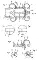
- the turbocharger 1 shown in Figure 1 has a typical Construction. He has a wave 2, on the right side a turbine wheel 3 and on the left a compressor 4 to sit.
- the shaft 2 is not shown here bearing stored in a tubular bearing housing 5. Camps can be designed as a magnetic bearing, as this For example, in DE 102 16 447 C1 discloses.
- the turbine wheel 3 is surrounded by a turbine housing 6, the one not shown here radial inlet port Has.
- the compressor 4 is of a compressor housing 9 surrounded, with a central inlet opening 10 is provided. About this inlet opening 10 is sucked 4 air due to the rotational movement of the compressor wheel and deflected into an annular space 11. This condensed Air then leaves the annulus 11 via a here Aulschreibö réelle not shown in the direction of Inlet side of the internal combustion engine.
- the turbine housing 6 and the compressor housing 9 are with the bearing housing 5 via two flanges 12, 13th or 14, 15 connected.
- the flanges 12, 13 and 14, 15 are over here not shown screws in usual Way braced with each other.
- Figure 2 shows a wave detail adjacent to the turbine housing 6 or to the turbine wheel 3.
- a Intermediate piece 16 welded, made of a nickel-chromium alloy exists and therefore much worse directs than the otherwise made of a steel shaft 2.
- the intermediate piece 16 acts as an insulating layer and obstructed the heat transfer in the direction of the turbine wheel 3 and thus the bearing in the bearing housing. 5
- FIG. 3 shows another embodiment of a wave detail, which is arranged in the same place.
- the wave 2 is here provided with a cavity 17, which for the Heat conduction available cross-sectional area the shaft 2 reduced to an outer ring area and This hinders the heat transfer.
- Figure 4 shows the upper part of the bearing housing 5 and the adjacent turbine housing 6 without shaft 2 and without Turbine wheel 3.
- Figure 5 is a variant the flange connection between the bearing housing. 5 and the turbine housing 6.
- an insulating layer 18 is arranged, the heat transfer from the turbine housing. 6 reduced to the bearing housing 5.
- the heat transfer between the flanges 12, 13 can but also be hampered by the fact that the mutual Installation of the flanges 12, 13 takes place only via webs 19, 20, as can be seen in the detail of Figure 6.
- the Webs 19, 20 extend annularly over the entire Circumference of the flanges 12, 13 and therefore close one Cavity 21 a.
- the small cross-sectional area of the webs 19, 20 obstructs the heat conduction from the turbine housing 6 belonging flange 12 on the bearing housing 5 belonging Flange 13.
- the turbine housing 6 on an outer side be provided with a coating that the heat transfer improved to the environment, so a better thermal conductivity and / or a higher heat emissivity has as the material from which the turbine housing. 6 consists.
- the turbine housing 6 on his Inner side with a heat absorption reducing coating be provided.
Landscapes
- Engineering & Computer Science (AREA)
- Mechanical Engineering (AREA)
- General Engineering & Computer Science (AREA)
- Supercharger (AREA)
Abstract
Description
Die Erfindung betrifft einen Abgasturbolader mit einer Welle, die ein in einem Turbinengehäuse angeordnetes Turbinenrad und ein Verdichterrad verbindet, und mit einer dazwischen angeordneten Lagerung mit einem Lagergehäuse und darin angeordneten Lagern für die Welle.The invention relates to an exhaust gas turbocharger with a Shaft, which is a turbine wheel arranged in a turbine housing and a compressor wheel connects, and with a interposed storage with a bearing housing and bearings disposed therein for the shaft.
Abgasturbolader dienen der verbesserung des Wirkungsgrades und damit der Leistungssteigerung von Verbrennungmotoren. Sie weisen eine welle auf, die einerends mit einem Turbinenrad und anderenends mit einem Verdichterrad versehen ist. Das Turbinenrad wird von Abgasstrom des verbrennermotors beaufschlagt, wobei im wesentlichen die thermische Energie des Abgases durch das Turbinenrad in eine Drehbewegung umgesetzt wird. über die Welle wird das Verdichterrad angetrieben, das Frischluft ansaugt und mit Überdruck in die Einlaßkanäle des Verbrennungsmotors einströmen läßt und damit den Füllungsgrad verbessert. Exhaust gas turbochargers are used to improve the efficiency and thus the increase in performance of combustion engines. You have a wave on one end with a Turbine and the other end provided with a compressor wheel is. The turbine wheel is powered by exhaust gas from the combustion engine acted essentially the thermal energy of the exhaust gas through the turbine wheel in a rotational movement is implemented. that's going to be over the wave Compressor wheel driven, the fresh air sucks and with Overpressure to flow into the intake ports of the engine leaves and thus improves the degree of filling.
An die Lagerung der Welle von Abgasturboladern werden hohe Anforderungen gestellt. Zum einen erreicht die Welle hohe Drehzahlen von bis zu 300.000 U/min. Zum anderen wird der Abgasturbolader auf der Turbinenseite durch den Abgasstrom hohen Temperaturen ausgesetzt, die bei Ottomotoren mehr als 1.000° C erreichen können, während die Temperatur auf der Verdichterseite im allgemeinen nicht mehr als 150° C erreicht. Es versteht sich, daß hierdurch eine enorme thermische Belastung der Lager entsteht, die der Turbinenseite benachbart sind.At the storage of the shaft of exhaust gas turbochargers are high Requirements made. First, the wave reaches high speeds of up to 300,000 rpm. On the other hand is the turbocharger on the turbine side through the Exhaust gas flow exposed to high temperatures in gasoline engines can reach more than 1,000 ° C while the Temperature on the compressor side generally not reached more than 150 ° C. It is understood that thereby an enormous thermal load of the bearings arises, which are adjacent to the turbine side.
Bei Gleit- oder Kugellagern ist vor allem der Ölkreislauf durch Temperaturen dieser Größenordnung gefährdet. Bei Überschreiten kritischer Temperaturen entstehen Ölrückstände in Form von Kohleablagerungen, die nach relativ kurzer Zeit zum Ausfall des Abgasturboladers durch Festfressen der welle führen. Um die Aufheizung des Lagergehäuses in Grenzen zu halten, ist es bei Ottomotoren bekannt, das Lagergehäuse mit einem wasserkühlmantel zu versehen. Dies verteuert den Abgasturbolader.For sliding or ball bearings, especially the oil circuit endangered by temperatures of this magnitude. at Exceeding critical temperatures results in oil residues in the form of carbon deposits, which are relative to short time to failure of the exhaust gas turbocharger by seizure lead the wave. To heat the bearing housing to limit it, it is known in gasoline engines, the bearing housing with a water cooling jacket too Mistake. This makes the exhaust gas turbocharger more expensive.
In neuerer zeit sind vorschläge gemacht worden, die bisherigen Lager, also Gleit- oder Wälzlager, durch Magnetlager zu ersetzen und damit die Welle berührungslos zu führen (vgl. DE 102 16 447 C1). Diese haben den Vorteil, daß sie schmiermittelfrei betrieben werden können und deshalb die oben genannte Ausfallursache nicht gegeben ist. Die dabei zum Einsatz kommenden Permanentmagnete verlieren jedoch ihre magnetischen Eigenschaften bei einer Erwärmung auf höhere Temperaturen irreversibel.More recently proposals have been made, the previous ones Bearings, ie plain or roller bearings, by magnetic bearings to replace and thus the shaft without contact lead (see DE 102 16 447 C1). These have the advantage that they can be operated without lubricant and Therefore, the above failure cause is not given is. The permanent magnets used for this purpose but lose their magnetic properties at a Heating to higher temperatures irreversible.
Der Erfindung liegt somit die Aufgabe zugrunde, einen Abgasturbolader der eingangs genannten Art so auszubilden, daß mit kostengünstigen Maßnahmen eine Erwärmung der Lager auf Temperaturen, die ihre Betriebssicherheit beeinträchtigen, vermieden wird.The invention is therefore based on the object, an exhaust gas turbocharger of the type mentioned above in such a way that with cost-effective measures, a warming of the bearings to temperatures that affect their operational safety, is avoided.
Diese Aufgabe wird erfindungsgemäß dadurch gelöst, daß die Welle zwischen Turbinenrad und Lagerung wenigstens eine wärmeisolierung aufweist, deren Wärmedurchlässigkeit geringer ist als die der an die Wärmeisolierung angrenzenden Bereiche der Welle und die den Wärmedurchgang durch die Welle behindert. Dem liegt die Erkenntnis zugrunde, daß ein wesentlicher Teil der auf Turbinenseite entstehenden Wärme über die Welle in die Lagerung übertragen wird. Durch die wärmeisolierung wird die Wärmeübertragung auf die Lagerung herabgesetzt, wobei das Maß der Herabsetzung durch entsprechende Ausbildung der Wärmeisolierung und durch deren Dimensionierung an die jeweiligen Anforderungen angepaßt werden kann.This object is achieved in that the shaft between turbine wheel and bearing at least has a thermal insulation whose thermal permeability less than that adjacent to the thermal insulation Areas of the shaft and the heat transfer hampered by the wave. This is based on the knowledge that an essential part of the turbine side resulting heat transferred via the shaft in the storage becomes. Due to the heat insulation, the heat transfer reduced to storage, with the measure the reduction by appropriate training of thermal insulation and by dimensioning them to the respective ones Requirements can be adjusted.
In Ausbildung der Erfindung ist vorgesehen, daß die Wärmeisolierung eine über den Querschnitt der Welle gehende Isolierschicht aufweist, deren Wärmeleitfähigkeit geringer ist als die des Materials der welle ansonsten. Dabei muß die Isolierschicht so beschaffen sein, daß sie einerseits gegenüber den aufgetretenen Temperaturen standfest ist, andererseits aber auch die Welle nicht oder nicht zu stark geschwächt wird. Besonders geeignet sind aus Festigkeitsgründen Metalle, deren wärmeleitfähigkeit geringer, insbesondere erheblich geringer ist als das Material, aus dem die Welle im übrigen besteht, nämlich in der Regel Stahl. Als Metalle für die Isolierschicht kommen vor allem Nickel-Chrom-Legierungen in Frage, wie sie unter den Marken INCONEL® oder INCOLOY® bekannt sind, aber auch Edelstahllegierungen.In an embodiment of the invention it is provided that the thermal insulation one over the cross section of the wave going Insulating layer having a lower thermal conductivity otherwise than the material of the shaft. there the insulating layer must be such that on the one hand resistant to the temperatures encountered on the other hand, the wave is not or not is greatly weakened. For reasons of strength, they are particularly suitable Metals whose thermal conductivity is lower, especially considerably less than the material, from which the wave exists otherwise, namely in the Usually steel. As metals come for the insulating layer especially nickel-chromium alloys in question as they are under but the brands INCONEL® or INCOLOY® are known also stainless steel alloys.
Anstatt oder in Kombination mit einer Isolierschicht kann die Wärmeisolierung aber auch einen Bereich aufweisen, wo die Querschnittsfläche der Welle reduziert ist und auf diese Weise der Wärmedurchgang behindert wird. Dies kann beispielsweise dadurch geschehen, daß in die Welle ein Hohlraum eingeformt ist, wobei sich der Hohlraum auch über die gesamte Länge der welle erstrecken kann, also eine Hohlwelle vorliegt.Instead of or in combination with an insulating layer can the heat insulation but also have an area where the cross-sectional area of the shaft is reduced and on this way the heat transfer is hindered. This can For example, done by that in the shaft Cavity is formed, wherein the cavity also can extend over the entire length of the shaft, so a hollow shaft is present.
Die der Erfindung zugrunde liegende Aufgabe kann alternativ zu oder auch in Kombination mit den vorgenannten Maßnahmen dadurch gelöst werden, daß die Welle zwischen Turbinenrad und Lagerung und/oder das Lagergehäuse zusätzliche Wärmeübergangsflächen aufweist bzw. aufweisen. Diese zusätzlichen Wärmeübergangsflächen verbessern die Wärmeabfuhr an die Umgebung. Die wärmeübergangsflächen können beispielsweise als wenigstens eine auf der Welle sitzende Kühlscheibe ausgebildet sein.The object underlying the invention may alternatively to or in combination with the aforementioned measures be solved in that the shaft between the turbine wheel and storage and / or the bearing housing additional Have or have heat transfer surfaces. These additional heat transfer surfaces improve the heat dissipation to the environment. The heat transfer surfaces can for example, as at least one sitting on the shaft Cooling disk be formed.
Die der Erfindung zugrunde liegende Aufgabe kann alternativ zu oder in Kombination mit den vorgenannten Maßnahmen auch dadurch gelöst werden, daß die Flansche, über die Lagergehäuse und Turbinengehäuse miteinander gekoppelt sind, eine Wärmeisolierung aufweisen, deren Wärmedurchlässigkeit geringer ist als die der Flansche selbst. Auf diese Weise kann die durch Wärmeleitung über die Gehäuse bewirkte wärmeübertragung reduziert werden.The object underlying the invention may alternatively to or in combination with the above measures also be solved in that the flanges, on the Bearing housing and turbine housing coupled together are, have a thermal insulation whose thermal permeability less than that of the flanges themselves This way, the heat conduction through the housing caused heat transfer can be reduced.
Am einfachsten kann dies dadurch geschehen, daß die Wärmeisolierung eine Isolierschicht aufweist, deren Wärmeleitfähigkeit geringer ist als die des Materials der Flansche ansonsten und die zwischen den Flanschen angeordnet ist. Die Isolierschicht kann - wie bei der Wärmeisolierung der Welle - aus einem Metall, beispielsweise einer Nickel-Chrom-Legierung oder einer Edelstahllegierung, bestehen. Es können jedoch auch andere, schlecht wärmeleitende Materialien, insbesondere Mineral- oder Keramikmaterialien, verwendet werden.The easiest way this can be done by the heat insulation having an insulating layer whose thermal conductivity less than that of the material Otherwise flanges and arranged between the flanges is. The insulating layer can - as in the thermal insulation the wave - made of a metal, for example a nickel-chromium alloy or a stainless steel alloy, consist. However, others, too, can be bad thermally conductive materials, in particular mineral or ceramic materials, be used.
Statt oder in Kombination mit einer Isolierschicht kann die Wärmeisolierung Isolierstege aufweisen, über die die Flansche der Flanschverbindung aneinander liegen. Dem liegt der Gedanke zugrunde, die Flächen, über die die beiden Flansche aneinander liegen, möglichst klein zu halten. Dabei besteht die Möglichkeit, die Isolierstege so auszubilden, daß sie einen Hohlraum einschließen, der mit einem Isoliermaterial gefüllt sein kann.Instead of or in combination with an insulating layer can have the thermal insulation insulating webs over which the Flanges of the flange are adjacent to each other. the the idea is based on the surfaces over which the two flanges together, as small as possible hold. It is possible, the Isolierstege form so that they include a cavity, the can be filled with an insulating material.
Eine weitere Maßnahme zur Lösung der gestellten Aufgabe besteht darin, daß das Turbinengehäuse und/oder das Lagergehäuse außenseitig wenigstens teilweise mit einer Beschichtung versehen ist bzw. sind, die die Wärmeabgabe an die Umgebung verbessert. Auch diese Maßnahme kann mit den vorbeschriebenen Maßnahmen kombiniert werden, um die Schutzwirkung gegen Wärmebeanspruchung der Lager zu verbessern. Die Beschichtung kann eine bessere Wärmeleitfähigkeit haben als das Material des Turbinengehäuses bzw. des Lagergehäuses. So kann die Oberfläche durch Flammspritzen mit Aluminium versehen werden. Alternativ oder in Kombination sollte die Beschichtung auch ein höheres Wärmeemissionsvermögen haben als das Material des Turbinengehäuses bzw. Lagergehäuses.Another measure to solve the task is that the turbine housing and / or the bearing housing on the outside at least partially with a coating is or are the heat dissipation to the environment improved. Also this measure can with the The measures described above are combined to To improve protection against thermal stress of the bearings. The coating can have better thermal conductivity have as the material of the turbine housing or of the bearing housing. So can the surface by flame spraying be provided with aluminum. Alternatively or In combination, the coating should also be a higher one Heat emissivities have as the material of the turbine housing or bearing housing.
Schließlich besteht eine letzte Maßnahme zur Lösung der gestellten Aufgabe darin, das Turbinengehäuse auf seiner Innenseite wenigstens teilweise mit einer Beschichtung zu versehen, die die Wärmeaufnahme des Turbinengehäuses verringert. Die Beschichtung sollte ein geringeres Wärmeabsorptionsvermögen haben als das Material des Turbinengehäuses. Auf diese weise wird die Wärmeaufnahme des Gehäuses reduziert.Finally, there is a final measure to solve the task in it, the turbine housing on his Inner side at least partially with a coating too provided, which reduces the heat absorption of the turbine housing. The coating should have a lower heat absorption capacity have as the material of the turbine housing. In this way, the heat absorption of the housing reduced.
In der Zeichnung ist die Erfindung anhand von schematisch dargestellten Ausführungsbeispielen näher veranschaulicht. Es zeigen:
- Figur 1
- einen Längsschnitt durch einen Turbolader;
Figur 2- ein Wellendetail des Turboladers gemäß Figur 1 in der Seitenansicht;
Figur 3- ein weiteres Wellendetail des Turboladers gemäß Figur 1 in der Seitenansicht;
Figur 4- einen Gehäuseabschnitt des Turboladers gemäß Figur 1 im Längsschnitt;
Figur 5- ein Detail des Gehäuseabschnitts gemäß
Figur 4 im Längsschnitt; Figur 6- ein weiteres Detail des Gehäuseabschnitts gemäß
Figur 4 im Längsschnitt; - Figur 7
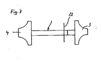
- die Seitenansicht eines Turbinenrades und eines verdichterrades, verbunden durch eine Welle, des Abgasturboladers gemäß Figur 1.
- FIG. 1
- a longitudinal section through a turbocharger;
- FIG. 2
- a wave detail of the turbocharger according to Figure 1 in side view;
- FIG. 3
- another wave detail of the turbocharger according to Figure 1 in side view;
- FIG. 4
- a housing section of the turbocharger according to Figure 1 in longitudinal section;
- FIG. 5
- a detail of the housing portion of Figure 4 in longitudinal section;
- FIG. 6
- a further detail of the housing section according to Figure 4 in longitudinal section;
- FIG. 7
- the side view of a turbine wheel and a compressor wheel, connected by a shaft, the exhaust gas turbocharger according to Figure 1.
Der in Figur 1 dargestellte Turbolader 1 hat einen typischen
Aufbau. Er hat eine welle 2, auf der rechtsseitig
ein Turbinenrad 3 und linksseitig ein Verdichterrad 4
sitzen. Die Welle 2 ist über hier nicht dargestellte Lager
in einem rohrartigen Lagergehäuse 5 gelagert. Die Lager
können als Magnetlager ausgebildet sein, wie dies
beispielsweise in der DE 102 16 447 C1 offenbart ist.The turbocharger 1 shown in Figure 1 has a typical
Construction. He has a
Das Turbinenrad 3 ist von einem Turbinengehäuse 6 umgeben,
das eine hier nicht näher dargestellte radiale Einlaßöffnung
hat. Das verdichterrad 4 ist von einem Verdichtergehäuse
9 umgeben, das mit einer zentralen Einlaßöffnung
10 versehen ist. Über diese Einlaßöffnung 10 wird
aufgrund der Drehbewegung des Verdichterrades 4 Luft angesaugt
und in einen Ringraum 11 umgelenkt. Diese verdichtete
Luft verläßt dann den Ringraum 11 über eine hier
nicht näher dargestellte Aulaßöffnung in Richtung der
Einlaßseite des Verbrennungsmotors.The
Das Turbinengehäuse 6 und das Verdichtergehäuse 9 sind
mit dem Lagergehäuse 5 über jeweils zwei Flansche 12, 13
bzw. 14, 15 verbunden. Die Flansche 12, 13 bzw. 14, 15
sind über hier nicht dargestellte Schrauben in üblicher
Weise miteinander verspannt.The
Figur 2 zeigt ein Wellendetail benachbart zum Turbinengehäuse
6 bzw. zum Turbinenrad 3. In die Welle 2 ist ein
Zwischenstück 16 eingeschweißt, das aus einer Nickel-Chrom-Legierung
besteht und deshalb wesentlich schlechter
leitet als die ansonsten aus einem Stahl bestehende Welle
2. Das Zwischenstück 16 wirkt als Isolierschicht und behindert
die Wärmeleitungsübertragung in Richtung des Turbinenrades
3 und damit der Lager im Lagergehäuse 5.Figure 2 shows a wave detail adjacent to the
Figur 3 zeigt eine andere Ausführungsform eines Wellendetails,
die an gleicher Stelle angeordnet ist. Die welle 2
ist hier mit einem Hohlraum 17 versehen, der die für die
Wärmeleitung zur Verfügung stehende Querschnittsfläche
der Welle 2 auf einen äußeren Ringbereich reduziert und
hierdurch die Wärmeübertragung behindert.FIG. 3 shows another embodiment of a wave detail,
which is arranged in the same place. The
Figur 4 zeigt den oberen Teil des Lagergehäuses 5 und des
angrenzenden Turbinengehäuses 6 ohne Welle 2 und ohne
Turbinenrad 3. In dem Detail gemäß Figur 5 ist eine variante
der Flanschverbindung zwischen dem Lagergehäuse 5
und dem Turbinengehäuse 6 dargestellt. Zwischen den beiden
Flanschen 12, 13 ist eine Isolierschicht 18 angeordnet,
die die Wärmeleitübertragung vom Turbinengehäuse 6
zum Lagergehäuse 5 reduziert.Figure 4 shows the upper part of the bearing
Die Wärmeübertragung zwischen den Flanschen 12, 13 kann
aber auch dadurch behindert werden, daß die gegenseitige
Anlage der Flansche 12, 13 nur über Stege 19, 20 erfolgt,
wie dies in dem Detail gemäß Figur 6 zu sehen ist. Die
Stege 19, 20 erstrecken sich ringförmig über den gesamten
Umfang der Flansche 12, 13 und schließen deshalb einen
Hohlraum 21 ein. Die geringe Querschnittsfläche der Stege
19, 20 behindert die Wärmeleitung vom zum Turbinengehäuse
6 gehörenden Flansch 12 auf den zum Lagergehäuse 5 gehörenden
Flansch 13.The heat transfer between the
In Figur 7 ist die Welle 2 mit dem Turbinenrad 3 und dem
Verdichterrad 4 ohne jedes Gehäuse dargestellt. Auf der
Welle 2 sitzt eine Kühlscheibe 22, die sich mit der Welle
2 dreht. Die Kühlscheibe 22 vergrößert die wärmeübertragungsfläche
an die Umgebung und sorgt durch ihre Drehbewegung
für eine die Wärmeableitung fördernde Konvektionsströmung.In Figure 7, the
Im übrigen kann das Turbinengehäuse 6 an einer Außenseite
mit einer Beschichtung versehen sein, die den Wärmeübergang
an die Umgebung verbessert, also eine bessere Wärmeleitfähigkeit
und/oder ein höheres Wärmeemissionsvermögen
hat als das Material, aus dem das das Turbinengehäuse 6
besteht. Zusätzlich kann das Turbinengehäuse 6 auf seiner
Innenseite mit einer die Wärmeaufnahme reduzierenden Beschichtung
versehen sein.Incidentally, the
Claims (20)
Priority Applications (1)
| Application Number | Priority Date | Filing Date | Title |
|---|---|---|---|
| EP07000729A EP1795711A2 (en) | 2004-05-18 | 2005-05-04 | Exhaust gas turbocharger |
Applications Claiming Priority (2)
| Application Number | Priority Date | Filing Date | Title |
|---|---|---|---|
| DE102004025049A DE102004025049A1 (en) | 2004-05-18 | 2004-05-18 | turbocharger |
| DE102004025049 | 2004-05-18 |
Related Child Applications (1)
| Application Number | Title | Priority Date | Filing Date |
|---|---|---|---|
| EP07000729A Division EP1795711A2 (en) | 2004-05-18 | 2005-05-04 | Exhaust gas turbocharger |
Publications (1)
| Publication Number | Publication Date |
|---|---|
| EP1598521A1 true EP1598521A1 (en) | 2005-11-23 |
Family
ID=34936133
Family Applications (2)
| Application Number | Title | Priority Date | Filing Date |
|---|---|---|---|
| EP07000729A Withdrawn EP1795711A2 (en) | 2004-05-18 | 2005-05-04 | Exhaust gas turbocharger |
| EP05009768A Withdrawn EP1598521A1 (en) | 2004-05-18 | 2005-05-04 | Exhaust gas turbocharger |
Family Applications Before (1)
| Application Number | Title | Priority Date | Filing Date |
|---|---|---|---|
| EP07000729A Withdrawn EP1795711A2 (en) | 2004-05-18 | 2005-05-04 | Exhaust gas turbocharger |
Country Status (4)
| Country | Link |
|---|---|
| US (2) | US20050257522A1 (en) |
| EP (2) | EP1795711A2 (en) |
| JP (1) | JP2005330968A (en) |
| DE (1) | DE102004025049A1 (en) |
Cited By (1)
| Publication number | Priority date | Publication date | Assignee | Title |
|---|---|---|---|---|
| CN103850727A (en) * | 2012-11-28 | 2014-06-11 | 霍尼韦尔国际公司 | Suction sealing for turbocharger |
Families Citing this family (25)
| Publication number | Priority date | Publication date | Assignee | Title |
|---|---|---|---|---|
| JP2008202544A (en) * | 2007-02-21 | 2008-09-04 | Mitsubishi Heavy Ind Ltd | Manufacturing method of rotor, and exhaust turbocharger having the rotor |
| DE102008038007A1 (en) * | 2008-08-16 | 2010-02-18 | Bosch Mahle Turbo Systems Gmbh & Co. Kg | turbocharger |
| DE102008058507A1 (en) * | 2008-11-21 | 2010-05-27 | Bosch Mahle Turbo Systems Gmbh & Co. Kg | loader |
| DE102008058506A1 (en) * | 2008-11-21 | 2010-05-27 | Bosch Mahle Turbo Systems Gmbh & Co. Kg | Charging device, particularly exhaust gas turbocharger for motor vehicle, has compressor and turbine wheel, which has shaft |
| DE102009014005A1 (en) * | 2009-03-19 | 2010-09-23 | Bosch Mahle Turbo Systems Gmbh & Co. Kg | Rotating fluid flow engine for exhaust turbocharger for internal combustion engine of motor vehicle, has rotor with compressor wheel and turbine wheel, where rotor is supported around rotational axis in fluid flow engine in pivoting manner |
| US9896967B2 (en) * | 2009-05-19 | 2018-02-20 | Borgwarner Inc. | Turbocharger |
| DE102009023891A1 (en) * | 2009-06-04 | 2011-03-31 | Continental Automotive Gmbh | Magnet-supported rotor shaft for exhaust-gas turbocharger that is used for petrol or diesel engines, has heat pipe provided in interior of rod-shaped shaft body, where longitudinal axis of pipe coincides with longitudinal axis of body |
| DE102009058411A1 (en) * | 2009-12-16 | 2011-06-22 | BorgWarner Inc., Mich. | turbocharger |
| DE102010011486A1 (en) | 2010-03-16 | 2011-09-22 | Bosch Mahle Turbo Systems Gmbh & Co. Kg | Rotor for a charging device |
| US20110280716A1 (en) * | 2010-05-17 | 2011-11-17 | Douglas Gerard Konitzer | Gas turbine engine compressor components comprising thermal barriers, thermal barrier systems, and methods of using the same |
| DE102010050913A1 (en) | 2010-11-11 | 2012-05-16 | Pierburg Gmbh | Supercharger for commercial vehicle engine, has compressor wheel arranged at end of shaft in compressor housing, flange members connected together by clamping member, and bearing housing and turbine housing provided with clamping surfaces |
| CN103518049B (en) * | 2011-05-10 | 2017-05-17 | 博格华纳公司 | Exhaust turbocharger and its bearing housing |
| ES2470322T3 (en) * | 2011-11-09 | 2014-06-23 | Isolite Gmbh | Multi-part turbine housing for a turbocharger |
| DE112012004142T5 (en) * | 2011-11-23 | 2014-06-26 | Borgwarner Inc. | turbocharger |
| CN103946514B (en) * | 2011-12-09 | 2016-09-14 | 博格华纳公司 | Bearing housing for exhaust turbocharger |
| WO2013148412A1 (en) * | 2012-03-27 | 2013-10-03 | Borgwarner Inc. | Systems and methods for protecting a turbocharger aluminum bearing housing |
| TWM446226U (en) * | 2012-09-04 | 2013-02-01 | Tan Xin Technology Dev Inc | Housing of turbocharger |
| DE102014201732B4 (en) | 2013-02-28 | 2024-03-28 | Ford Global Technologies, Llc | Internal combustion engine with a liquid-cooled turbine |
| DE102013111562A1 (en) * | 2013-10-21 | 2015-04-23 | Ihi Charging Systems International Gmbh | turbocharger |
| DE102014201411A1 (en) * | 2014-01-27 | 2015-08-13 | Ford Global Technologies, Llc | Internal combustion engine with cooled turbine |
| US10041400B2 (en) * | 2016-05-20 | 2018-08-07 | Borgwarner Inc. | Hollow filled turbocharger rotor shaft |
| US10690136B2 (en) | 2016-11-04 | 2020-06-23 | Ford Global Technologies, Llc | Supercharged internal combustion engine with compressor |
| DE102016221639B4 (en) * | 2016-11-04 | 2021-11-25 | Ford Global Technologies, Llc | Supercharged internal combustion engine with a cooled compressor |
| US10487741B2 (en) * | 2018-02-27 | 2019-11-26 | GM Global Technology Operations LLC | Turbo vane and compressor for turbocharger |
| JP7490508B2 (en) * | 2020-09-09 | 2024-05-27 | 日本電子株式会社 | 3D additive manufacturing equipment |
Citations (3)
| Publication number | Priority date | Publication date | Assignee | Title |
|---|---|---|---|---|
| US4557704A (en) * | 1983-11-08 | 1985-12-10 | Ngk Spark Plug Co., Ltd. | Junction structure of turbine shaft |
| US5129784A (en) * | 1990-08-23 | 1992-07-14 | Ngk Spark Plug Co., Ltd. | Ceramic rotor and metal shaft assembly |
| US5174733A (en) * | 1990-08-22 | 1992-12-29 | Ngk Spark Plug Co., Ltd. | Supercharger |
Family Cites Families (13)
| Publication number | Priority date | Publication date | Assignee | Title |
|---|---|---|---|---|
| US2008414A (en) * | 1931-12-04 | 1935-07-16 | Eugene H Fischer | Insulator |
| US4083180A (en) * | 1976-10-01 | 1978-04-11 | Caterpillar Tractor Co. | Gas turbine engine internal insulation |
| DE2829150A1 (en) * | 1978-07-03 | 1980-01-24 | Barmag Barmer Maschf | EXHAUST TURBOCHARGER |
| JPS5939930A (en) * | 1982-08-27 | 1984-03-05 | Nissan Motor Co Ltd | Turbocharger |
| JPS5949323A (en) * | 1982-09-10 | 1984-03-21 | Toyota Central Res & Dev Lab Inc | turbo machine |
| DE3413388A1 (en) * | 1984-04-10 | 1985-10-24 | Aktiengesellschaft Kühnle, Kopp & Kausch, 6710 Frankenthal | Exhaust turbo charger |
| JPS60226464A (en) * | 1984-04-20 | 1985-11-11 | 日本特殊陶業株式会社 | Joint structure of ceramic and metal |
| JPH0352987Y2 (en) * | 1984-10-04 | 1991-11-19 | ||
| JPS6267237A (en) * | 1985-09-18 | 1987-03-26 | Hitachi Ltd | Dual passage type exhaust drive turbocharger |
| US4907952A (en) * | 1986-12-05 | 1990-03-13 | Honda Giken Kogyo Kabushiki Kaisha | Turbocharger |
| DD255369A1 (en) * | 1986-12-22 | 1988-03-30 | Bannewitz Kompressorenbau | Thermal insulation for bearings of a waste gas cooler with uncooled hulls |
| JPH05155668A (en) * | 1991-12-09 | 1993-06-22 | Ngk Spark Plug Co Ltd | Combined body of ceramics and metal |
| DE19931150A1 (en) * | 1999-07-06 | 2001-01-11 | Volkswagen Ag | Exhaust gas turbocharger for vehicle engines has a turbine wheel with a catalytically active surface |
-
2004
- 2004-05-18 DE DE102004025049A patent/DE102004025049A1/en not_active Withdrawn
-
2005
- 2005-05-04 EP EP07000729A patent/EP1795711A2/en not_active Withdrawn
- 2005-05-04 EP EP05009768A patent/EP1598521A1/en not_active Withdrawn
- 2005-05-17 US US11/130,158 patent/US20050257522A1/en not_active Abandoned
- 2005-05-18 JP JP2005145171A patent/JP2005330968A/en not_active Withdrawn
-
2007
- 2007-01-12 US US11/652,572 patent/US20070113552A1/en not_active Abandoned
Patent Citations (3)
| Publication number | Priority date | Publication date | Assignee | Title |
|---|---|---|---|---|
| US4557704A (en) * | 1983-11-08 | 1985-12-10 | Ngk Spark Plug Co., Ltd. | Junction structure of turbine shaft |
| US5174733A (en) * | 1990-08-22 | 1992-12-29 | Ngk Spark Plug Co., Ltd. | Supercharger |
| US5129784A (en) * | 1990-08-23 | 1992-07-14 | Ngk Spark Plug Co., Ltd. | Ceramic rotor and metal shaft assembly |
Cited By (2)
| Publication number | Priority date | Publication date | Assignee | Title |
|---|---|---|---|---|
| CN103850727A (en) * | 2012-11-28 | 2014-06-11 | 霍尼韦尔国际公司 | Suction sealing for turbocharger |
| CN103850727B (en) * | 2012-11-28 | 2017-08-01 | 霍尼韦尔国际公司 | The suction sealing of turbocharger |
Also Published As
| Publication number | Publication date |
|---|---|
| DE102004025049A1 (en) | 2005-12-15 |
| JP2005330968A (en) | 2005-12-02 |
| EP1795711A2 (en) | 2007-06-13 |
| US20070113552A1 (en) | 2007-05-24 |
| US20050257522A1 (en) | 2005-11-24 |
Similar Documents
| Publication | Publication Date | Title |
|---|---|---|
| EP1598521A1 (en) | Exhaust gas turbocharger | |
| DE10028160C2 (en) | Housing group for the turbine of an exhaust gas turbocharger | |
| EP2499378B1 (en) | Turbocharger housing | |
| DE3631130C2 (en) | ||
| EP0136741B1 (en) | Piston for internal-combustion engines | |
| DE19804232C2 (en) | Combustion chamber for high-performance engines and nozzles | |
| DE102009040196A1 (en) | Exhaust gas turbocharger for an internal combustion engine | |
| DE2829150A1 (en) | EXHAUST TURBOCHARGER | |
| DE102019104499B4 (en) | Turbine and compressor for turbochargers | |
| DE102015114935B4 (en) | Turbocharger with boost pressure control valve | |
| DE3843663A1 (en) | HEAT INSULATION FOR HOT GAS LEADING CASTING COMPONENTS | |
| DE3232925A1 (en) | TURBOCHARGER WITH DIVIDED TURBINE HOUSING | |
| DE102008038007A1 (en) | turbocharger | |
| DE102010013702A1 (en) | Turbine for exhaust gas turbocharger, particularly for motor vehicle, has turbine housing and waste gate-valve which has waste gate-flap that controls flue gas volume passing through waste gate-valve | |
| EP1225314A2 (en) | Exhaust manifold for flue gas discharge out of an internal combustion engine | |
| EP2054597B1 (en) | Emergency oil tank | |
| EP3452702B1 (en) | Turbine housing for a turbocharger of an internal combustion engine, and turbocharger | |
| WO2006056394A2 (en) | Exhaust-gas turbo charger for an internal combustion engine | |
| DE102021127333A1 (en) | Fuel cell charging system | |
| DE19648641A1 (en) | Heat-protection device for turbine bearing | |
| DE112010002048T5 (en) | turbocharger | |
| EP3159505A1 (en) | Module for a gas turbine | |
| DE102021127331A1 (en) | Fuel cell charging system | |
| EP1544416A2 (en) | Bearing assembly for a gas turbine rotor | |
| EP3260662A1 (en) | Storage element and turbo engine with a storage element |
Legal Events
| Date | Code | Title | Description |
|---|---|---|---|
| PUAI | Public reference made under article 153(3) epc to a published international application that has entered the european phase |
Free format text: ORIGINAL CODE: 0009012 |
|
| AK | Designated contracting states |
Kind code of ref document: A1 Designated state(s): AT BE BG CH CY CZ DE DK EE ES FI FR GB GR HU IE IS IT LI LT LU MC NL PL PT RO SE SI SK TR |
|
| AX | Request for extension of the european patent |
Extension state: AL BA HR LV MK YU |
|
| 17P | Request for examination filed |
Effective date: 20060522 |
|
| AKX | Designation fees paid |
Designated state(s): DE FR GB IT NL |
|
| 17Q | First examination report despatched |
Effective date: 20060705 |
|
| STAA | Information on the status of an ep patent application or granted ep patent |
Free format text: STATUS: THE APPLICATION IS DEEMED TO BE WITHDRAWN |
|
| 18D | Application deemed to be withdrawn |
Effective date: 20070116 |