EP1544416A2 - Bearing assembly for a gas turbine rotor - Google Patents
Bearing assembly for a gas turbine rotor Download PDFInfo
- Publication number
- EP1544416A2 EP1544416A2 EP04028512A EP04028512A EP1544416A2 EP 1544416 A2 EP1544416 A2 EP 1544416A2 EP 04028512 A EP04028512 A EP 04028512A EP 04028512 A EP04028512 A EP 04028512A EP 1544416 A2 EP1544416 A2 EP 1544416A2
- Authority
- EP
- European Patent Office
- Prior art keywords
- turbine
- gas turbine
- bearing
- rotor
- thrust bearing
- Prior art date
- Legal status (The legal status is an assumption and is not a legal conclusion. Google has not performed a legal analysis and makes no representation as to the accuracy of the status listed.)
- Withdrawn
Links
Images

Classifications
-
- F—MECHANICAL ENGINEERING; LIGHTING; HEATING; WEAPONS; BLASTING
- F02—COMBUSTION ENGINES; HOT-GAS OR COMBUSTION-PRODUCT ENGINE PLANTS
- F02C—GAS-TURBINE PLANTS; AIR INTAKES FOR JET-PROPULSION PLANTS; CONTROLLING FUEL SUPPLY IN AIR-BREATHING JET-PROPULSION PLANTS
- F02C7/00—Features, components parts, details or accessories, not provided for in, or of interest apart form groups F02C1/00 - F02C6/00; Air intakes for jet-propulsion plants
- F02C7/06—Arrangements of bearings; Lubricating
-
- F—MECHANICAL ENGINEERING; LIGHTING; HEATING; WEAPONS; BLASTING
- F01—MACHINES OR ENGINES IN GENERAL; ENGINE PLANTS IN GENERAL; STEAM ENGINES
- F01D—NON-POSITIVE DISPLACEMENT MACHINES OR ENGINES, e.g. STEAM TURBINES
- F01D3/00—Machines or engines with axial-thrust balancing effected by working-fluid
-
- F—MECHANICAL ENGINEERING; LIGHTING; HEATING; WEAPONS; BLASTING
- F01—MACHINES OR ENGINES IN GENERAL; ENGINE PLANTS IN GENERAL; STEAM ENGINES
- F01D—NON-POSITIVE DISPLACEMENT MACHINES OR ENGINES, e.g. STEAM TURBINES
- F01D25/00—Component parts, details, or accessories, not provided for in, or of interest apart from, other groups
- F01D25/16—Arrangement of bearings; Supporting or mounting bearings in casings
-
- F—MECHANICAL ENGINEERING; LIGHTING; HEATING; WEAPONS; BLASTING
- F05—INDEXING SCHEMES RELATING TO ENGINES OR PUMPS IN VARIOUS SUBCLASSES OF CLASSES F01-F04
- F05D—INDEXING SCHEME FOR ASPECTS RELATING TO NON-POSITIVE-DISPLACEMENT MACHINES OR ENGINES, GAS-TURBINES OR JET-PROPULSION PLANTS
- F05D2240/00—Components
- F05D2240/50—Bearings
- F05D2240/52—Axial thrust bearings
-
- F—MECHANICAL ENGINEERING; LIGHTING; HEATING; WEAPONS; BLASTING
- F05—INDEXING SCHEMES RELATING TO ENGINES OR PUMPS IN VARIOUS SUBCLASSES OF CLASSES F01-F04
- F05D—INDEXING SCHEME FOR ASPECTS RELATING TO NON-POSITIVE-DISPLACEMENT MACHINES OR ENGINES, GAS-TURBINES OR JET-PROPULSION PLANTS
- F05D2240/00—Components
- F05D2240/50—Bearings
- F05D2240/54—Radial bearings
Definitions
- the invention relates to the arrangement for mounting the rotor a gas turbine with the features of the preamble of Claim.
- the invention is based on the object, the generic Storage of a turbine rotor to be designed so that the Relative strains between the turbine rotor and the Turbine stator decreases and that causes the gap between These parts can be downsized.
- the thrust bearing in the To arrange inlet region of the compressor part of the gas turbine was under the aspect of an efficiency gain According to the invention, the thrust bearing in the region of the turbine part laid.
- the thrust bearing and the support bearing in the area of the turbine part can basically be carried out separately. Is advantageous but also if the support bearing and the thrust bearing together in the Are arranged portion of the turbine part.
- bearings are preferably tilting pad bearing or Gleit vomläger provided. Furthermore you can advantageously arranged lubrication bearing such as magnetic bearings become.
- the support bearing as Gleitlagerlager be executed while the thrust bearing as Tilting segment bearing is formed.
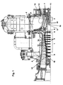
- the gas turbine consists of a compressor part 1, a Combustion chamber 2 and a turbine part 3.
- a Turbine housing 4 runs around a rotor 5, which in the compressor part 1 and in the turbine part 3 of discs 6, 7 is constructed.
- the Washers 6 of the compressor part 1 are by bolts. 8 with each other and with an end part 9 and with a Rotors middle part 10 connected.
- the discs 7 of the turbine part 3 are also penetrating through the discs bolt 11th connected to each other and with the rotor central part 10. On their Scope wear the discs 6, 7 blades 12, 13. Between the rotor blades 12, 13 are arranged vanes 14, 15, which are fixed to the wall of the turbine housing 4.
- the rotor 5 is mounted in two radial support bearings 16, 17.
- the a support bearing 16 is in the inlet region of the compressor part. 1 arranged and surrounds the end portion 9 of the rotor 5, while the other support bearing 17 is provided in the region of the turbine part 3 is and the rotor central part 10 surrounds.
- a thrust bearing 19 In the area of Turbine part 3 is further arranged a thrust bearing 19, the the axial load of the rotor 5 catches.
- the bearings will be with Lubricating oil supplied via oil-bearing holes as well Oil supply and drain lines from the side of the turbine part 3 forth is provided. The lubricating oil ensures at the same time an intensive cooling of the bearing assembly.
- the bearing assembly preferably includes tilting pad bearings. It but can also multi-surface bearings, bearings, magnetic bearings or other types of bearings.
- Figs. 3a and 3b Due to the fact that the thrust bearing 19 deviating from the previous Construction is arranged in the region of the hot turbine part 3, is the thermally induced axial elongation of the rotor 5 in Limited turbine area. What advantage that with itself brings is schematically illustrated in Figs. 3a and 3b.
- the Blades 13 of the turbine part 3 are conical and without outer shroud executed. Between the tips of the rotating blades 13 and the wall of the fixed Turbine housing 4 is in the idle state of the gas turbine Game 20 of predetermined size ⁇ r (Fig. 3a). Will the Gas turbine from the idle state into the operating state (FIG. 3b) offset, so experiences the rotor 5 due to Temperature load a thermal elongation ⁇ l in axial Direction.
Abstract
Description
Die Erfindung betrifft die Anordnung zur Lagerung des Rotors einer Gasturbine mit den Merkmalen des Oberbegriffes des Patentanspruches.The invention relates to the arrangement for mounting the rotor a gas turbine with the features of the preamble of Claim.
In bekannten Gasturbinenanlagen (Ch. Lechner/J. Seume, Stationäre Gasturbinen, Springer-Verlag, 2003, Seiten 720-723) ist das Drucklager zur axialen Festlegung des Rotors im Eintrittsbereich des Verdichterteiles angeordnet. Diese Anordnung wurde stets gewählt, weil der Platzbedarf im Eintrittsbereich des Verdichterteiles verhältnismäßig günstig und dort das Drucklager verhältnismäßig einfach zugänglich ist. Da das Drucklager im Vergleich zu dem radialen Traglager bedeutend mehr Öl benötigt, lassen sich die Ölzufuhr- und die Ölablaufleitungen im Eintrittsbereich des Verdichterteiles verhältnismäßig einfach unterbringen.In known gas turbine plants (Ch Lechner / J. Seume, Stationary Gas Turbines, Springer-Verlag, 2003, pages 720-723) is the thrust bearing for axially fixing the rotor in Entry region of the compressor part arranged. These Arrangement was always chosen because of the space requirement in the Entry area of the compressor part relatively cheap and there the thrust bearing is relatively easily accessible. Since the thrust bearing compared to the radial support bearing significantly more oil needed, can the oil supply and the Oil drain lines in the inlet area of the compressor section relatively easy to accommodate.
Während des Betriebes der Gasturbine kommt es zu einer Erwärmung der Bauteile. Die unterschiedliche Erwärmung der Bauteile führt zu axialen Relativverschiebungen zwischen den Rotorkomponenten und den Statorkomponenten der Gasturbine. Die axialen Relativverschiebungen wachsen mit dem Abstand des Turbinenbauteiles vom Drucklager und führen bei deckbandlosen und konischen Schaufeln zu einer Vergrößerung des Spieles zwischen Laufschaufel und Statorwand während des Überganges vom Ruhezustand in den Betriebszustand der Gasturbine.During operation of the gas turbine there is a warming of the components. The different heating of the components leads to axial relative displacements between the rotor components and the stator components of the gas turbine. The axial Relative displacements increase with the distance of the Turbine components from the thrust bearing and lead in deckbandlosen and conical blades to increase the game between blade and stator wall during the transition from Sleep state in the operating state of the gas turbine.
Der Erfindung liegt die Aufgabe zugrunde, die gattungsgemäße Lagerung eines Turbinenrotors so zu gestalten, dass die Relativdehnungen zwischen dem Turbinenrotor und dem Turbinenstator verringert und dass damit die Spalte zwischen diesen Teilen verkleinert werden können. The invention is based on the object, the generic Storage of a turbine rotor to be designed so that the Relative strains between the turbine rotor and the Turbine stator decreases and that causes the gap between These parts can be downsized.
Die Aufgabe wird bei einer gattungsgemäßen Lagerung erfindungsgemäß durch das kennzeichnende Merkmal des Patentanspruchs gelöst.The task is in a generic storage according to the invention by the characterizing feature of Patent claim solved.
Vorteilhafte Ausgestaltungen der Erfindung sind in den Unteransprüchen angegeben.Advantageous embodiments of the invention are in the Subclaims specified.
Obwohl bisher gute Gründe dafür sprachen, das Drucklager in dem Eintrittsbereich des Verdichterteiles der Gasturbine anzuordnen, wurde unter dem Gesichtspunkt eines Wirkungsgradgewinnes erfindungsgemäß das Drucklager in den Bereich des Turbinenteiles verlegt.Although there were good reasons to date, the thrust bearing in the To arrange inlet region of the compressor part of the gas turbine, was under the aspect of an efficiency gain According to the invention, the thrust bearing in the region of the turbine part laid.
Durch das turbinenseitig angeordnete Drucklager werden die Axialdehnungen des Turbinenteiles minimiert. Dadurch wird das Spiel verringert, das sich während des Überganges von dem Ruhezustand in den Betriebszustand zwischen den Laüfschaufeln und der Statorwand einstellt. Das verringerte Spiel führt zu einer Verringerung der Strömungsverluste und damit zu einer Erhöhung des Wirkungsgrades.By the turbine side arranged thrust bearing are the Axial expansions of the turbine part minimized. This will do that Reduced play during the transition of the Sleep state in the operating state between the Laüfschaufeln and adjusts the stator wall. The reduced game leads to a reduction of flow losses and thus to a Increase in efficiency.
Gleichzeitig kann die für das Drucklager erforderliche höhere Ölmenge in dem heißen Bereich des Turbinenteiles für eine intensivere Kühlung des Lagergehäuses genutzt werden. Eine solche intensivere Kühlung des Lagergehäuses trägt mit dazu bei, der Forderung nach erhöhten Turbineneintrittstemperaturen entgegenzukommen.At the same time required for the thrust bearing higher Oil quantity in the hot area of the turbine part for a intensive cooling of the bearing housing can be used. A such more intensive cooling of the bearing housing contributes to the demand for increased turbine inlet temperatures meet.
Das Drucklager und das Traglager im Bereich des Turbinenteils können grundsätzlich separat ausgeführt werden. Vorteilhaft ist jedoch auch, wenn das Traglager und das Drucklager zusammen im Bereich des Turbinenteiles angeordnet sind. The thrust bearing and the support bearing in the area of the turbine part can basically be carried out separately. Is advantageous but also if the support bearing and the thrust bearing together in the Are arranged portion of the turbine part.
Als Lager sind vorzugsweise Kippsegmentlager oder auch Gleitflächenläger vorgesehen. Weiterhin können vorteilhafterweise schmierlose Lager wie Magnetlager angeordnet werden. Für besondere Anordnungen können die Traglager als Gleitflächenlager ausgeführt sein, während das Drucklager als Kippsegmentlager ausgebildet ist.As bearings are preferably tilting pad bearing or Gleitflächenläger provided. Furthermore you can advantageously arranged lubrication bearing such as magnetic bearings become. For special arrangements, the support bearing as Gleitlagerlager be executed while the thrust bearing as Tilting segment bearing is formed.
Ein Ausführungsbeispiel der Erfindung ist in der Zeichnung
dargestellt und wird im Folgenden näher erläutert. Es zeigen:
Die Gasturbine besteht aus einem Verdichterteil 1, einer
Brennkammer 2 und einem Turbinenteil 3. Innerhalb eines
Turbinengehäuses 4 läuft ein Rotor 5 um, der im Verdichterteil 1
und im Turbinenteil 3 aus Scheiben 6, 7 aufgebaut ist. Die
Scheiben 6 des Verdichterteiles 1 sind durch Bolzen 8
miteinander sowie mit einem Endteil 9 und mit einem
Rotormittelteil 10 verbunden. Die Scheiben 7 des Turbinenteiles
3 sind ebenfalls durch die Scheiben durchdringende Bolzen 11
miteinander und mit dem Rotormittelteil 10 verbunden. Auf ihrem
Umfang tragen die Scheiben 6, 7 Laufschaufeln 12, 13. Zwischen
den Laufschaufeln 12, 13 sind Leitschaufeln 14, 15 angeordnet,
die an der Wand des Turbinengehäuses 4 befestigt sind.The gas turbine consists of a compressor part 1, a
Der Rotor 5 ist in zwei radialen Traglagern 16, 17 gelagert. Das
eine Traglager 16 ist im Eintrittsbereich des Verdichterteiles 1
angeordnet und umgibt das Endteil 9 des Rotors 5, während das
andere Traglager 17 im Bereich des Turbinenteiles 3 vorgesehen
ist und das Rotormittelteil 10 umgibt. Im Bereich des
Turbinenteiles 3 ist weiterhin ein Drucklager 19 angeordnet, das
die Axialbelastung des Rotors 5 auffängt. Die Lager werden mit
Schmieröl versorgt, das über ölführende Bohrungen sowie
Ölzufuhr- und Ölablaufleitungen von der Seite des Turbinenteiles
3 her bereitgestellt wird. Das Schmieröl sorgt gleichzeitig für
eine intensive Kühlung der Lageranordnung.The
Die Lageranordnung enthält vorzugsweise Kippsegmentlager. Es können aber auch Mehrflächengleitlager, Wälzlager, Magnetlager oder andere Lagertypen verwendet werden.The bearing assembly preferably includes tilting pad bearings. It but can also multi-surface bearings, bearings, magnetic bearings or other types of bearings.
Dadurch, dass das Drucklager 19 abweichend von der bisherigen
Bauweise im Bereich des heißen Turbinenteiles 3 angeordnet ist,
wird die thermisch bedingte axiale Längendehnung des Rotors 5 im
Turbinenbereich eingeschränkt. Welchen Vorteil das mit sich
bringt, ist schematisch in den Fig. 3a und 3b verdeutlicht. Die
Laufschaufeln 13 des Turbinenteiles 3 sind konisch und ohne
äußeres Deckband ausgeführt. Zwischen den Spitzen der
rotierenden Laufschaufeln 13 und der Wand des feststehenden
Turbinengehäuses 4 besteht im Ruhezustand der Gasturbine ein
Spiel 20 von vorgegebener Größe Δr (Fig. 3a). Wird die
Gasturbine aus dem Ruhezustand in den Betriebszustand (Fig. 3b)
versetzt, so erfährt der Rotor 5 aufgrund der
Temperaturbelastung eine thermische Längendehnung Δl in axialer
Richtung.Due to the fact that the thrust bearing 19 deviating from the previous
Construction is arranged in the region of the
Ist - wie vorgesehen - das Drucklager 19 auf der dem
Verdichterteil 1 zugewandten Seite des Turbinenteiles 3
angeordnet, so führt bei konischen Laufschaufeln 13 die axiale
Längendehnung Δl zu einer Vergrößerung des Spieles 20 um den
Wert Δr* auf den Wert Δr'. Eine solche Vergrößerung des Spieles
20 führt zu Strömungsverlusten und damit zu einer Verringerung
des Wirkungsgrades der Gasturbine. Durch die erfindungsgemäße
Anordnung des Drucklagers 19 im Bereich des Turbinenteiles 3
kann die Vergrößerung des Spieles 20 aufgrund der axialen
Längendehnung des Rotors 5 in engeren Grenzen gehalten werden,
wodurch eine Verbessung des Wirkungsgrades der Gasturbine
erreicht wird.Is - as intended - the thrust bearing 19 on the
Compressor part 1 facing side of the turbine part. 3
arranged, so leads in
Claims (6)
Applications Claiming Priority (2)
| Application Number | Priority Date | Filing Date | Title |
|---|---|---|---|
| DE10358953 | 2003-12-15 | ||
| DE10358953A DE10358953A1 (en) | 2003-12-15 | 2003-12-15 | Storage of the rotor of a gas turbine |
Publications (2)
| Publication Number | Publication Date |
|---|---|
| EP1544416A2 true EP1544416A2 (en) | 2005-06-22 |
| EP1544416A3 EP1544416A3 (en) | 2007-02-28 |
Family
ID=34485411
Family Applications (1)
| Application Number | Title | Priority Date | Filing Date |
|---|---|---|---|
| EP04028512A Withdrawn EP1544416A3 (en) | 2003-12-15 | 2004-12-02 | Bearing assembly for a gas turbine rotor |
Country Status (9)
| Country | Link |
|---|---|
| US (1) | US7175385B2 (en) |
| EP (1) | EP1544416A3 (en) |
| JP (1) | JP2005180436A (en) |
| KR (1) | KR20050060000A (en) |
| CN (1) | CN1629464A (en) |
| CA (1) | CA2489655A1 (en) |
| DE (1) | DE10358953A1 (en) |
| RU (1) | RU2004136569A (en) |
| UA (1) | UA79119C2 (en) |
Families Citing this family (9)
| Publication number | Priority date | Publication date | Assignee | Title |
|---|---|---|---|---|
| US8434997B2 (en) * | 2007-08-22 | 2013-05-07 | United Technologies Corporation | Gas turbine engine case for clearance control |
| US8794923B2 (en) * | 2010-10-29 | 2014-08-05 | United Technologies Corporation | Gas turbine engine rotor tie shaft arrangement |
| US8544268B2 (en) * | 2011-05-25 | 2013-10-01 | GM Global Technology Operations LLC | Engine assembly including turbocharger |
| RU2529294C1 (en) * | 2013-08-07 | 2014-09-27 | Федеральное Государственное Автономное Образовательное Учреждение Высшего Профессионального Образования "Дальневосточный Федеральный Университет" (Двфу) | Gas turbine engine |
| RU2528891C1 (en) * | 2013-08-08 | 2014-09-20 | Федеральное Государственное Автономное Образовательное Учреждение Высшего Профессионального Образования "Дальневосточный Федеральный Университет" (Двфу) | Gas turbine engine |
| RU2528889C1 (en) * | 2013-08-12 | 2014-09-20 | Федеральное Государственное Автономное Образовательное Учреждение Высшего Профессионального Образования "Дальневосточный Федеральный Университет" (Двфу) | Gas turbine engine |
| EP3444441B1 (en) * | 2017-08-14 | 2020-04-08 | General Electric Company | Gas turbine engine with inlet frame |
| KR101939495B1 (en) | 2017-09-21 | 2019-01-16 | 두산중공업 주식회사 | Compressor and gas turbine comprising it |
| CN113586245B (en) * | 2021-08-31 | 2022-04-26 | 中国联合重型燃气轮机技术有限公司 | Gas turbine's strutting arrangement and gas turbine |
Citations (4)
| Publication number | Priority date | Publication date | Assignee | Title |
|---|---|---|---|---|
| US2732695A (en) | 1956-01-31 | davis | ||
| US3601495A (en) | 1968-09-20 | 1971-08-24 | Rolls Royce | Bearing assembly |
| DE2209713A1 (en) | 1971-03-03 | 1972-09-21 | Detude Et De Construction De M | Turbo engine |
| JPH04124496A (en) | 1990-09-17 | 1992-04-24 | Hitachi Ltd | Fluid machine |
Family Cites Families (25)
| Publication number | Priority date | Publication date | Assignee | Title |
|---|---|---|---|---|
| US2625790A (en) * | 1948-10-28 | 1953-01-20 | Rolls Royce | Rotary fluid machine assembly |
| DE1200075B (en) | 1959-08-04 | 1965-09-02 | Commissariat Energie Atomique | Dynamic slide bearing |
| GB937684A (en) * | 1961-06-30 | 1963-09-25 | Rolls Royce | Bearing assembly |
| GB1080747A (en) | 1964-09-29 | 1967-08-23 | English Electric Co Ltd | Improvements in or relating to turbines |
| US4178754A (en) * | 1976-07-19 | 1979-12-18 | The Hydragon Corporation | Throttleable turbine engine |
| NL7800077A (en) | 1978-01-03 | 1979-07-05 | Thomassen Holland Bv | GASTURBINE INSTALLATION. |
| IT1135752B (en) | 1981-04-17 | 1986-08-27 | Nuovo Pignone Spa | IMPROVEMENTS IN THE POWER STAGE OF A GAS TURBINE |
| GB2099923A (en) * | 1981-06-06 | 1982-12-15 | Rolls Royce | Shaft lifting apparatus |
| FI66234C (en) | 1981-10-13 | 1984-09-10 | Jaakko Larjola | ENERGIOMVANDLARE |
| JPS5985302U (en) | 1982-11-30 | 1984-06-09 | 日本特殊陶業株式会社 | Turbine shaft joint |
| DE3414910A1 (en) | 1984-04-19 | 1985-10-24 | A. Friedr. Flender Gmbh & Co Kg, 4290 Bocholt | Tilting-pad sliding bearing |
| JPS6173919U (en) * | 1984-10-23 | 1986-05-19 | ||
| US4738550A (en) | 1986-09-08 | 1988-04-19 | Waukesha Bearings Corporation | Tilting pad thrust bearing with optimized tilt axis location |
| US4965994A (en) * | 1988-12-16 | 1990-10-30 | General Electric Company | Jet engine turbine support |
| US4900221A (en) * | 1988-12-16 | 1990-02-13 | General Electric Company | Jet engine fan and compressor bearing support |
| US5160251A (en) * | 1991-05-13 | 1992-11-03 | General Electric Company | Lightweight engine turbine bearing support assembly for withstanding radial and axial loads |
| DE9215696U1 (en) | 1992-11-18 | 1994-03-17 | Piller Gmbh Co Kg Anton | Power generation plant |
| US5749700A (en) * | 1996-07-17 | 1998-05-12 | Allison Engine Company, Inc. | High speed, high temperature hybrid magnetic thrust bearing |
| US6151909A (en) * | 1998-03-13 | 2000-11-28 | Alliedsignal Inc. | Two spool air cycle machine having concentric shafts |
| US6246138B1 (en) * | 1998-12-24 | 2001-06-12 | Honeywell International Inc. | Microturbine cooling system |
| GB9904221D0 (en) * | 1999-02-25 | 1999-04-21 | Rolls Royce Plc | Gas turbine engine bearing arrangement |
| EP1171705B1 (en) | 1999-03-10 | 2008-02-13 | Williams International Co., L.L.C. | Rocket engine |
| DE10030698A1 (en) * | 2000-06-23 | 2002-01-10 | Gleitlagertechnik Weissbacher | Process for lubricating and cooling a hydrodynamic plain bearing and device for carrying out this process |
| US6571563B2 (en) * | 2000-12-19 | 2003-06-03 | Honeywell Power Systems, Inc. | Gas turbine engine with offset shroud |
| JP3943013B2 (en) * | 2002-12-26 | 2007-07-11 | 株式会社竹中工務店 | Vertical thermal power plant |
-
2003
- 2003-12-15 DE DE10358953A patent/DE10358953A1/en not_active Ceased
-
2004
- 2004-12-02 EP EP04028512A patent/EP1544416A3/en not_active Withdrawn
- 2004-12-07 CA CA002489655A patent/CA2489655A1/en not_active Abandoned
- 2004-12-08 US US11/007,817 patent/US7175385B2/en not_active Expired - Fee Related
- 2004-12-10 UA UA20041210180A patent/UA79119C2/en unknown
- 2004-12-13 KR KR1020040104799A patent/KR20050060000A/en not_active Application Discontinuation
- 2004-12-14 RU RU2004136569/06A patent/RU2004136569A/en not_active Application Discontinuation
- 2004-12-14 JP JP2004361777A patent/JP2005180436A/en active Pending
- 2004-12-15 CN CNA2004100819851A patent/CN1629464A/en active Pending
Patent Citations (4)
| Publication number | Priority date | Publication date | Assignee | Title |
|---|---|---|---|---|
| US2732695A (en) | 1956-01-31 | davis | ||
| US3601495A (en) | 1968-09-20 | 1971-08-24 | Rolls Royce | Bearing assembly |
| DE2209713A1 (en) | 1971-03-03 | 1972-09-21 | Detude Et De Construction De M | Turbo engine |
| JPH04124496A (en) | 1990-09-17 | 1992-04-24 | Hitachi Ltd | Fluid machine |
Non-Patent Citations (1)
| Title |
|---|
| CH. LECHNER/J; SEUME: "Stationäre Gasturbinen", 2003, SPRINGER-VERLAG, pages: 720 - 723 |
Also Published As
| Publication number | Publication date |
|---|---|
| US20050129506A1 (en) | 2005-06-16 |
| UA79119C2 (en) | 2007-05-25 |
| DE10358953A1 (en) | 2005-07-28 |
| US7175385B2 (en) | 2007-02-13 |
| KR20050060000A (en) | 2005-06-21 |
| CN1629464A (en) | 2005-06-22 |
| JP2005180436A (en) | 2005-07-07 |
| EP1544416A3 (en) | 2007-02-28 |
| CA2489655A1 (en) | 2005-06-15 |
| RU2004136569A (en) | 2006-05-27 |
Similar Documents
| Publication | Publication Date | Title |
|---|---|---|
| DE3642121C2 (en) | ||
| EP0840027B1 (en) | Sliding axial bearing | |
| EP1898054B1 (en) | Gas turbine | |
| DE69934846T2 (en) | Steam turbine with brush seal | |
| DE69827555T2 (en) | gas turbine | |
| DE10210866C5 (en) | Guide vane mounting in a flow channel of an aircraft gas turbine | |
| DE102006004836A1 (en) | Organic rankine cycle-turbo-generator, has generator section with stator housing that includes rotor chamber, which opens in direction of exhaust chamber of turbine section, where generator is provided between generator and turbine sections | |
| DE202007018540U1 (en) | Organic Rankine Cycle (ORC) - Turbogenerator | |
| WO2008129046A2 (en) | Axial bearing, particularly for a turbocharger | |
| EP1778953A1 (en) | Exhaust turbine cleaning device | |
| WO2006021520A1 (en) | Injection of liquid into a gas turbine during a cooling phase | |
| EP1391586A1 (en) | Turbocharger | |
| EP1970532A1 (en) | Rotor of a thermal fluid flow engine and gas turbine | |
| EP1544416A2 (en) | Bearing assembly for a gas turbine rotor | |
| EP2084368A1 (en) | Turbine blade | |
| DE102014108594A1 (en) | Turbocharger arrangement with directly mounted bearing housing | |
| EP1206627B1 (en) | Turbine and method for discharging leakage fluid | |
| DE19652754A1 (en) | Exhaust gas supercharger | |
| WO2009109430A1 (en) | Sealing arrangement and gas turbine | |
| EP2802748B1 (en) | Turbomachine with bolt cooling | |
| WO2009092792A2 (en) | Exhaust gas turbocharger | |
| EP2284426B1 (en) | Turbomachine | |
| EP2113638A1 (en) | Spraying device | |
| EP1970528A1 (en) | Rotor of a thermal fluid flow engine | |
| EP2347100B1 (en) | Gas turbine having cooling insert |
Legal Events
| Date | Code | Title | Description |
|---|---|---|---|
| PUAI | Public reference made under article 153(3) epc to a published international application that has entered the european phase |
Free format text: ORIGINAL CODE: 0009012 |
|
| AK | Designated contracting states |
Kind code of ref document: A2 Designated state(s): AT BE BG CH CY CZ DE DK EE ES FI FR GB GR HU IE IS IT LI LT LU MC NL PL PT RO SE SI SK TR |
|
| AX | Request for extension of the european patent |
Extension state: AL BA HR LV MK YU |
|
| PUAL | Search report despatched |
Free format text: ORIGINAL CODE: 0009013 |
|
| AK | Designated contracting states |
Kind code of ref document: A3 Designated state(s): AT BE BG CH CY CZ DE DK EE ES FI FR GB GR HU IE IS IT LI LT LU MC NL PL PT RO SE SI SK TR |
|
| AX | Request for extension of the european patent |
Extension state: AL BA HR LV MK YU |
|
| 17P | Request for examination filed |
Effective date: 20070426 |
|
| 17Q | First examination report despatched |
Effective date: 20070706 |
|
| AKX | Designation fees paid |
Designated state(s): AT BE BG CH CY CZ DE DK EE ES FI FR GB GR HU IE IS IT LI LT LU MC NL PL PT RO SE SI SK TR |
|
| 18D | Application deemed to be withdrawn |
Effective date: 20110701 |
|
| STAA | Information on the status of an ep patent application or granted ep patent |
Free format text: STATUS: THE APPLICATION IS DEEMED TO BE WITHDRAWN |
|
| R18D | Application deemed to be withdrawn (corrected) |
Effective date: 20110625 |