EP1171705B1 - Rocket engine - Google Patents
Rocket engine Download PDFInfo
- Publication number
- EP1171705B1 EP1171705B1 EP00946747A EP00946747A EP1171705B1 EP 1171705 B1 EP1171705 B1 EP 1171705B1 EP 00946747 A EP00946747 A EP 00946747A EP 00946747 A EP00946747 A EP 00946747A EP 1171705 B1 EP1171705 B1 EP 1171705B1
- Authority
- EP
- European Patent Office
- Prior art keywords
- combustion chamber
- rotary
- rocket engine
- inlet
- recited
- Prior art date
- Legal status (The legal status is an assumption and is not a legal conclusion. Google has not performed a legal analysis and makes no representation as to the accuracy of the status listed.)
- Expired - Lifetime
Links
Images


Classifications
-
- F—MECHANICAL ENGINEERING; LIGHTING; HEATING; WEAPONS; BLASTING
- F02—COMBUSTION ENGINES; HOT-GAS OR COMBUSTION-PRODUCT ENGINE PLANTS
- F02K—JET-PROPULSION PLANTS
- F02K9/00—Rocket-engine plants, i.e. plants carrying both fuel and oxidant therefor; Control thereof
- F02K9/42—Rocket-engine plants, i.e. plants carrying both fuel and oxidant therefor; Control thereof using liquid or gaseous propellants
- F02K9/44—Feeding propellants
- F02K9/52—Injectors
-
- F—MECHANICAL ENGINEERING; LIGHTING; HEATING; WEAPONS; BLASTING
- F02—COMBUSTION ENGINES; HOT-GAS OR COMBUSTION-PRODUCT ENGINE PLANTS
- F02K—JET-PROPULSION PLANTS
- F02K9/00—Rocket-engine plants, i.e. plants carrying both fuel and oxidant therefor; Control thereof
- F02K9/42—Rocket-engine plants, i.e. plants carrying both fuel and oxidant therefor; Control thereof using liquid or gaseous propellants
- F02K9/44—Feeding propellants
- F02K9/46—Feeding propellants using pumps
- F02K9/48—Feeding propellants using pumps driven by a gas turbine fed by propellant combustion gases or fed by vaporized propellants or other gases
-
- F—MECHANICAL ENGINEERING; LIGHTING; HEATING; WEAPONS; BLASTING
- F02—COMBUSTION ENGINES; HOT-GAS OR COMBUSTION-PRODUCT ENGINE PLANTS
- F02K—JET-PROPULSION PLANTS
- F02K9/00—Rocket-engine plants, i.e. plants carrying both fuel and oxidant therefor; Control thereof
- F02K9/42—Rocket-engine plants, i.e. plants carrying both fuel and oxidant therefor; Control thereof using liquid or gaseous propellants
- F02K9/60—Constructional parts; Details not otherwise provided for
- F02K9/62—Combustion or thrust chambers
- F02K9/64—Combustion or thrust chambers having cooling arrangements
-
- F—MECHANICAL ENGINEERING; LIGHTING; HEATING; WEAPONS; BLASTING
- F02—COMBUSTION ENGINES; HOT-GAS OR COMBUSTION-PRODUCT ENGINE PLANTS
- F02K—JET-PROPULSION PLANTS
- F02K9/00—Rocket-engine plants, i.e. plants carrying both fuel and oxidant therefor; Control thereof
- F02K9/42—Rocket-engine plants, i.e. plants carrying both fuel and oxidant therefor; Control thereof using liquid or gaseous propellants
- F02K9/60—Constructional parts; Details not otherwise provided for
- F02K9/62—Combustion or thrust chambers
- F02K9/66—Combustion or thrust chambers of the rotary type
-
- F—MECHANICAL ENGINEERING; LIGHTING; HEATING; WEAPONS; BLASTING
- F02—COMBUSTION ENGINES; HOT-GAS OR COMBUSTION-PRODUCT ENGINE PLANTS
- F02K—JET-PROPULSION PLANTS
- F02K9/00—Rocket-engine plants, i.e. plants carrying both fuel and oxidant therefor; Control thereof
- F02K9/72—Rocket-engine plants, i.e. plants carrying both fuel and oxidant therefor; Control thereof using liquid and solid propellants, i.e. hybrid rocket-engine plants
-
- F—MECHANICAL ENGINEERING; LIGHTING; HEATING; WEAPONS; BLASTING
- F05—INDEXING SCHEMES RELATING TO ENGINES OR PUMPS IN VARIOUS SUBCLASSES OF CLASSES F01-F04
- F05D—INDEXING SCHEME FOR ASPECTS RELATING TO NON-POSITIVE-DISPLACEMENT MACHINES OR ENGINES, GAS-TURBINES OR JET-PROPULSION PLANTS
- F05D2240/00—Components
- F05D2240/40—Use of a multiplicity of similar components
Definitions
- the present invention generally relates to fluid propellant rocket engines and more particularly to fluid propellant rocket engines that integrate as a single unit the turbomachinery for pumping the fluid propellant together with the main combustion chamber of the rocket.
- Liquid fuel rocket engines for example as taught in U.S. Patent Nos. 4,879.874 . 4,901,525 . and 5,267,437 generally employ turbomachinery that is distinct from the main rocket nozzle for pressurizing and/or gasifying the liquid propellants prior to injection into the main rocket nozzle. Furthermore, one or more of the propellant components may be adapted to cool the main rocket nozzle through a associated plumbing circuitry. Accordingly, such systems are generally costly and complex, and the added complexity tends to reduce reliability.
- U.S. Patents 3,541,793 and 3,577,735 teaches a turborocket engine wherein liquid propellants are pressurized by respective pumps that pressurize a liquid fuel and liquid oxidizer.
- One of the propellant components discharges first through the walls of the main combustion chamber for cooling purposes, and then into a precombustion chamber. A portion of the other propellant component is discharged in the precombustion chamber, and the remainder is discharged into the main combustion chamber.
- the effluent from the precombustion chamber drives a turbine that in turn drives the respective pumps.
- the effluent then discharges into the main combustion chamber.
- the discharge nozzles are stationary relative to the respective combustion chambers, which can result in temperature variations within the precombustion chamber than can be stressful to the turbine. Further, the use of liquid propellant for cooling the main combustion chamber increases cost, complexity and weight.
- U. S. Patent 5,323,602 teaches an effusion cooling system for a gas turbine engine that uses air as the cooling medium. This patent does not teach a turborocket engine, nor does it teach the use of combustion gases from a precombustor for effusion cooling a main combustor.
- US-A-3 307 359 discloses a rocket engine and method of operating a rocket engine according to the respective preambles of claims 1 and 11.
- a rocket engine comprising:
- a method of operating a rocket engine comprising:
- Liquid fuel and liquid oxidizer are provided from pressurized tanks at relatively low pressure to separate sections within a rotor system driven by a relatively low pressure ratio turbine that is powered the combustion effluent generated by a precombustor operated at a relatively rich fuel/oxidizer ratio such that the temperature of the partially combusted effluent can be tolerated by the turbine.
- the flow rates of liquid fuel and liquid oxidizer are controlled at the relatively low supply pressure with separate throttle control valves, which provides for improved control that is less costly and more reliable.
- Rotary pressure traps incorporated in the rotor system isolate the relatively low pressure outlets of the respective throttle control valves from the relatively high pressures of the precombustor and main combustor.
- the rotor system imparts, by a centrifugal pumping means, rotational kinetic energy and centrifugal force to the liquid fuel and liquid oxidizer.
- the centrifugal pumping means comprises one or more longitudinal ribs or vanes on the inside surface of the outer wall of a hollow shaft portion with one or more discharge orifices in communication with one or more associated grooves formed between adjacent ribs or vanes.
- the pressure drop across the discharge orifices is relatively small, and the discharge orifices are not necessarily filled with fluid during normal operation.
- the centrifugal pumping means of the present invention does not, however, incorporate a diffuser to convert kinetic energy back to pressure energy, as incorporated in many conventional centrifugal pumps. All of the liquid fuel and some of the liquid oxidizer is injected by rotary injection into the precombustor, and then mixed, vaporized, and partially combusted therein. The temperature of the effluent from the precombustor is controlled by the associated fuel/oxidizer mixture ratio. The rotary injection process provides for a more uniform temperature distribution within the associated toroidal combustion zones within the precombustor, thereby enabling the turbine to operate at a temperature closer to the material-dependent peak operating temperature.
- the rotor system incorporates concentric hollow sections, wherein the liquid oxidizer is supplied through and pumped from the center of a hollow main shaft, and the liquid fuel is pumped from an annular chamber concentric therewith.
- the elements of the centrifugal pumps including the ribs/vanes and discharge orifices, are arranged and sized so as to not disturb the mechanical balance of the rotor system.
- the ribs/vanes and/or the discharge orifices may be non-uniformly spaced in accordance with this constraint.
- a portion of the effluent from the precombustor is directed through the precombustor liner, over the outside of the main combustor liner, and into the main combustor through effusion cooling holes so as to cool the main combustor by effusion cooling.
- a portion of the fuel either liquid or gaseous, may also be directed over the precombustor liner for cooling the precombustor, and then combined with the effluent stream used to cool the main combustor liner.
- a portion of the effusion cooling gases may be discharged in the main combustor so as to provide boundary layer cooling of the converging/diverging nozzle.
- the relative amount of liquid oxidizer that is delivered to the precombustor and to the main combustor is set by the design of the liquid oxidizer distribution system within the main rotor system.
- the liquid oxidizer pump discharge is split at the pump exit, feeding the smaller portion of the flow to a rotating injection device which delivers the oxidizer to the precombustor.
- the rotating injection device also incorporates a rotary pressure trap to isolate the precombustor pressure from the main combustor pressure, thereby preventing the flow of precombustor gas therebetween through the rotary injection device.
- a portion of the liquid fuel is also fed into a similar rotating injection device proximate to the same axial plane, resulting in mixing and atomizing of the two liquids as they are slung from the shaft system.
- Combustion of the mixture occurs simultaneously with this mixing and atomization.
- Additional liquid fuel is injected into the precombustor to assist in mixing and to control the mixture ratio to achieve the proper temperature as the gasses reach the turbine. Accordingly, the fuel/oxidizer mixture ratio may be controlled within specific zones within the precombustor, which provides for improved burn characteristics.
- An igniter such as a high temperature torch, is used to initiate combustion in the precombustor, after which the combustion is continuous and self-sustaining.
- the heat of combustion in the precombustor vaporizes the injected liquid fuel and liquid oxidizer injected therein, including any liquid fuel used for cooling the precombustor and/or main combustor liners.
- This effluent and the gases used for cooling the precombustor and/or main combustor are combined and combusted with the remainder of the liquid oxidizer that is fed through the center of the hollow shaft connecting the pump elements to the turbine, and is injected by rotary injection directly into the main combustor as it exists the shaft through a centrifugal pumping device.
- This high speed rotary injection atomizes the liquid oxidizer which rapidly vaporizes and completes the combustion of the hot fuel rich gasses exiting the turbine directly into the main combustor.
- the end of the hollow shaft that is exposed to the hot combustion gases of the main combustor may be adapted to provide for the cooling or venting thereof by the discharge of gaseous oxidizer therefrom.
- the end of the hollow shaft may also or alternatively be polished or coated to provide thermal insulation from the hot combustion gases.
- the final or overall fuel/oxidizer mixture ratio is adjusted in accordance with a particular objective function, such as maximum thrust subject to constraints on the relative size of the associated propellant tanks.
- liquid oxidizer pump can be located downstream of where the liquid oxidizer flow is divided between the precombustor and the main combustor.
- one object of the present invention is to provide a lower cost turborocket engine.
- a further object of the present invention is to provide a turborocket engine with improved reliability.
- both the fuel and oxidizer are injected as liquids into the respective combustion chambers.
- both the fuel and oxidizer are injected as cryogenic liquids into the respective combustion chambers.
- a precombustor and a main combustor with a turbine disposed therebetween wherein the turbine drives a pumping means that pumps all of the liquid fuel and a portion of the liquid oxidizer into the precombustor, the fuel/oxidizer mixture ratio controlled such that the precombustor effluent temperature can be tolerated by the turbine, and the remainder of the liquid oxidizer is combined with the effluent from the precombustor/turbine for best overall combustion.
- vapor core centrifugal pumps for pumping and injecting the liquid fuel and liquid oxidizer.
- Liquid fuel and liquid oxidizer may be injected in the respective combustion chambers by rotary injection.
- Rotary pressure traps may be provided that isolate the liquid propellants from the pressure of the combustion chambers.
- Liquid fuel and liquid oxidizer may be controlled at the relatively low associated supply pressures, as from associated pressurized tanks.
- the main combustor may be effusion cooled with effluent from the precombustor.
- One advantage of the present invention with respect to the prior art is that a substantial amount of plumbing and machinery associated with conventional liquid propellant rocket engines can be eliminated, thereby reducing cost and improving reliability.
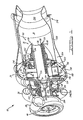
- a rocket engine 10 with a first end 12 and a second end 14 directs thrust from the second end 14 along an axis 16.
- First 18' and second 20' propellant components for example liquid oxygen 18 and liquid hydrogen 20 respectively, are fed from respective sources 22', 24', for example respective first and second pressurized tanks 22, 24, through respective first 26' and second 28' inlets, for example respective scrolls 26, 28, and into a single rotor system 30 that contains a pumping means 32 for pumping the liquid oxygen 18 and liquid hydrogen 20 into first 34' and second 36' combustion chambers , for example a precombustor 34 and a main combustor 36 respectively.
- At least a portion of the effluent 38 from the outlet 39 of the precombustor 34 drives a turbine 40 that rotates the rotor system 30. All, or most, of the hydrogen is fed to the precombustor 34 but the precombustor 34 receives only sufficient oxygen to raise its efflux temperature to a level that can be easily tolerated by the turbine 40 .
- the hydrogen rich effluent 38 discharged by of the turbine 40, along with any hydrogen that bypasses the turbine 40, is fed to the main combustor 36 where the remainder of the oxygen is introduced so as to provide an overall fuel/oxidizer mixture ratio within the main combustor 36 appropriate for the particular fuel/oxidizer system, whereby the combustion within the main combustor 36 provides the very high temperatures normally associated with rocket engines.
- the oxidizer/fuel mass ratio is preferably about 5.5:1, but could be any known mixture ratio or range of mixture ratios capable of supporting combustion.
- a mixture ratio of 2.8:1 LH 2 :LO 2 provides for the highest impulse, albeit with the associated disadvantage of requiring undesirably large liquid hydrogen storage tanks.
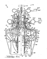
- the rotor system 30 comprises a shaft 44 having first 46 and second 48 hollow shaft portions adjacent and coupled and open to one another.
- the inside diameter of at least a portion of the second hollow shaft portion 48 is greater than that of the first hollow shaft portion 46.
- Liquid oxygen 18 is fed from the oxygen tank 22 into the oxygen scroll 26 at the first end 12 of the rocket engine 10 at a pressure of about 30 psig, through a plurality of flow directing vanes 49 , and into a stationary tube 50 that extends through and inside a first end 52 of the first hollow shaft portion 46 .
- the total quantity of oxygen supplied to the rocket engine 10 is regulated by a moveable conical throttle element 54 forming a controlled first throttling restriction 56 that restricts the flow of oxygen from of the stationary tube 50.
- the conical throttle element 54 is positioned by a rod 58 actuated by a first controller 60 from the first end 12 of the rocket engine 10 .
- Liquid oxygen 18 passing through the first throttling restriction 56 is directed into an interior 62 of the second hollow shaft portion 48 of the rotating shaft 44 , which contains a first inducer 64 comprising at least one screw-like vane that provides combined axial and rotational acceleration of the liquid oxygen 18 so as to induce the liquid oxygen 18 to rotate with the shaft 44 , while minimizing the joule heating and resulting vaporization as a result of mechanical agitation by the inducing process.
- the rotation of the shaft 44 generates centrifugal forces that cause the liquid oxygen 18 to gravitate towards the inside surface 66 of the shaft 44 thereby driving any oxygen vapor 68 towards the center 70 of the shaft 44 , which is vented by at least one vent duct 71 towards the outside of the stationary tube 50.
- the centrifugal separation of liquid oxygen 18 and oxygen vapor 68 causes the rotating first hollow shaft portion 46 to fill with oxygen vapor 68, which discharges into a fixed first annular vent chamber 72 , through a vent port 73, and into a fixed second annular vent chamber 74, from where the oxygen vapor 68 is vented from the rocket engine 10.
- a first rotary injector 76 coupled to the shaft 44, particularly to the second hollow shaft portion 48 , within the precombustor 34 comprises at least one first rotary orifice 78 in fluid communication with an inlet 80 and with the precombustor 34 .
- the inlet 80 of the first rotary injector 76 is in fluid communication with the oxygen scroll 26 that supplies liquid oxygen 18 through an associated fluid path in the respective interiors 82,62 of the first 46 and second 48 hollow shaft portions .
- the first rotary orifice 78 rotates with the shaft 44 about the axis 16 thereof.
- the first rotary injector 76 further comprises at least one first rotary pressure trap 86 comprising a first fluid passage 88 having an inlet 90 and an outlet 92 in fluid communication there through along a length thereof.
- the first fluid passage 88 is adapted so that when rotated about the axis of rotation 16 , a centrifugal acceleration at any point within the first fluid passage 88 is greater than a centrifugal acceleration at either the inlet 90 or the outlet 92 thereof.
- the second hollow shaft portion 48 further comprises a third hollow shaft portion 94 comprising a plurality of longitudinal ribs 96 and grooves 98 on the inside thereof.
- the longitudinal grooves 98 constitute a portion of a fluid passage 100 between the oxygen scroll 26 and the first rotary injector 76 .
- each longitudinal groove 98 receives an equal flow of liquid oxygen 18 from the first inducer 64 .
- the longitudinal grooves 98 may be non-uniformly sized-within the constraint of rotational balance, - resulting in corresponding nonuniform liquid oxygen flow rates within the respective longitudinal grooves 98.
- At least one first groove 102 is in fluid communication with the inlet 80 of the first rotary injector 76 .
- the second hollow shaft portion 48 further comprises a fourth hollow shaft portion 104 into which at least one second groove 106 extends from the third hollow shaft portion 94 to fourth hollow shaft portion 104 along the inside thereof. Referring to Fig. 5 , those first grooves 102 that do not extend into the fourth hollow shaft portion 104 are blocked at by associated annular dam segments 108 between the third 94 and fourth 104 hollow shaft portions .
- Liquid oxygen 18 flowing along the first grooves 102 discharges through the respective first rotary orifices 78 into the precombustor 34 .
- This arrangement precludes the need for separate servo-control of liquid oxygen flow into the precombustor 34 .
- each longitudinal groove 98 that is discharged through a first rotary orifice 78 into the precombustor 34 approximately five (5) longitudinal groove 98 discharge through the third rotary orifices 109 into the main combustor 36.
- the radial injection of liquid oxygen 18 from the rotating shaft 44 into both the precombustor 34 and the main combustor 36 provides for even circumferential distribution and atomization thereof therein.
- liquid hydrogen 20 is delivered from the associated pressurised hydrogen tank 24 into the hydrogen scroll 28 at a pressure of approximately 15 psig.
- the liquid hydrogen 20 flows radially inward from the hydrogen scroll 28 through a second throttling restriction 110 controlled by throttle ring 112 that is positioned by at least one control rod 114 through the case 116 and connected to a second controller 118 .
- the liquid hydrogen 20 flows through a curved annular flow diverter 120 that redirects the flow from radially inward to axial.
- the curved annular flow diverter 120 may incorporate vanes to impart pre-swirl to the flow.
- the liquid hydrogen 20 discharges from the curved annular flow diverter 120 into the interior 122 of an annular duct 124 in the rotor system 30 and into a second inducer 126 contained therein and rotating therewith.
- the second inducer 126 comprises at least one screw-like vane that provides combined axial and rotational acceleration of the liquid hydrogen 20 so as to induce the liquid hydrogen 20 to rotate with the shaft 44 , while minimizing the joule heating and resulting vaporization as a result of mechanical agitation by the inducing process.
- the annular duct 124 expands in diameter, wherein centrifugal forces cause liquid hydrogen 20 within the annular duct 124 to gravitate towards the outermost region 128 thereof, thereby displacing hydrogen vapor 130 therein towards the interior 122 thereof.
- a first labyrinth seal 134 disposed between the outside of the second hollow shaft portion 48 and the structure of the curved annular flow diverter 120 meters the leakage of hydrogen vapor 130 from the annular duct 124 through a first vent duct 136 into an third annular vent chamber 138 from where the hydrogen vapor 130 is vented from the rocket engine 10 .
- a first seal 140 for example a carbon seal, operative between the outside of the rotating annular duct 124 and the fixed third annular vent chamber 138 , seals against the leakage of hydrogen from the fixed annular flow diverter 120 , around the rotating annular duct 124 and into the fixed third annular vent chamber 138 .
- the main liquid hydrogen flow is delivered outwardly from the rotating annular duct 124 into a second rotary injector 142 coupled to the shaft 44, particularly to the second hollow shaft portion 48 , within the precombustor 34 .
- the second rotary injector 142 comprises at least one second rotary orifice 144 in fluid communication with the annular duct 124 and with the precombustor 34 .
- the second rotary orifice 144 rotates with the shaft 44 about the axis 16 thereof.
- the second rotary injector 142 further comprises at least one second rotary pressure trap 146 comprising a second fluid passage 148 having an inlet 150 and an outlet 152 in fluid communication there through along a length thereof.
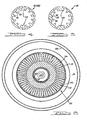
- each outlet 152 of each second rotary pressure trap 146 is in fluid communication with an annular manifold 154 , which is in fluid communication with an annular chamber 156 partitioned by a plurality of radial vanes 158 into a plurality of radial chambers 160 , at least some of which discharge into respective second rotary orifices 144 .
- the radial vanes 158 cause liquid hydrogen 20 within the annular chamber 156 to rotate therewith, and the resulting centrifugal force produces a large pressure gradient in the rotating liquid hydrogen 20 and a high discharge pressure at the second rotary orifices 144 .
- the second rotary orifices 144 are preferably disposed at various axial locations so as to provide for improved mixing and combustion within the precombustor 34 . Furthermore, a portion or all of the second rotary orifices 144 may be angulated relative to a radial direction. The locations, orientations, and sizes of the associated second rotary orifices 144 are adapted so that the rotor system 30 is mechanically balanced..
- liquid hydrogen 20 does not completely fill either the annular duct 124 or the annular chamber 156 , which collectively act as a vapor core pump.
- the second fluid passage 148 of the second rotary pressure trap 146 remains loaded with liquid hydrogen 20 so as to prevent backflow of high pressure vapor from the region downstream of the second rotary pressure trap 146 .
- the second hollow shaft portion 48 further comprises a shaft liner 162 having a closed end 164 and a second end 166 , each respectively proximate to a first end 168 and a second end 170 of the second hollow shaft portion 48 , wherein the closed end 164 of the shaft liner 162 is shaped so as to form a boundary 172 of a third rotary pressure trap 174 .
- the third rotary pressure trap 174 comprises a third fluid passage 176 having an inlet 178 and an outlet 180 in fluid communication there through along a length thereof.
- the third fluid passage 176 is adapted by the boundary 172 so that when rotated about the axis of rotation 16 a centrifugal acceleration at any point within the third fluid passage 176 is greater than a centrifugal acceleration at either the inlet 178 or the outlet 180.
- a third rotary injector 182 located within the main combustor 36 comprises at least one third rotary orifice 109 at the second end 170 of the second hollow shaft portion 48 in fluid communication with at least one second groove 106 and with the main combustor 36 , wherein the at least one second groove 106 is in fluid communication with the outlet 180 of the third rotary pressure trap 174 in the fluid path from the oxygen scroll 26 that supplies liquid oxygen 18 to the third rotary orifice 109 .
- the third rotary orifice 109 is coupled to the shaft 44, particularly to the fourth hollow shaft portion 104 , and rotates with the shaft 44 about the axis 16 thereof.
- liquid oxygen 18 from the pressurized oxygen tank 22 through the interior of the stationary tube 50 inside the first hollow shaft portion 46 discharges outwardly from the first throttling restriction 56 into the second hollow shaft portion 48 and is rotationally accelerated by the first inducer 64 causing the liquid oxygen 18 to rotate with the shaft 44.
- Resulting centrifugal forces pressurize the liquid oxygen 18 in proportion to the square of the radius from the center 70 of the shaft 44 , causing the liquid oxygen 18 to flow along the inside surface of the second hollow shaft portion 48.
- Liquid oxygen 18 fills the third fluid passage 176 of the third rotary pressure trap 174, and with a sufficient shaft speed, the third fluid passage 176 remains sufficiently full of liquid oxygen 18 to isolate high pressures of the main combustor 36 downstream of the third rotary pressure trap 174 from the relatively low pressure of the liquid oxygen 18 upstream of the third rotary pressure trap 174.
- a rotary pressure trap comprises a fluid passage with an inlet and an outlet, wherein the fluid passage adapted so the when the rotary pressure trap is rotated, a centrifugal acceleration at any point within the fluid passage is greater than a centrifugal acceleration at any point on either the inlet or the outlet. Accordingly, when the fluid passage is filled with a relatively high density medium, such as a liquid, the radial levels of the inlet and outlet will be equal when there is no pressure differential therebetween, and will be otherwise unequal by an amount dependent upon the magnitude of the pressure differential and the speed of rotation. Accordingly, for a relatively low pressur liquid supply to an inlet of a rotary pressure trap feeding a relatively high pressure region at the outlet, the rotary pressure trap can prevent vapor from backflowing therethrough.
- a relatively high density medium such as a liquid
- the first rotary pressure trap 86 isolates the liquid oxygen 18 at the inlet 80 of the first rotary injector 76 at the pressure of the main combustor 36 from the relatively higher pressure gases in the precombustor 34 .
- the second rotary pressure trap 146 isolates the liquid hydrogen 20 in the annular duct 124 at the supply pressure from the relatively higher pressure gases in the precombustor 34 .
- the third rotary pressure trap 174 isolates the liquid oxygen 18 from the first throttling restriction 56 at the supply pressure from the relatively higher pressure gases in the precombustor 34 .
- the second rotary orifices 144 discharge entirely within the precombustor 34 .
- some of the second rotary orifices 144 may be adapted so as to discharge a bypass flow 185 of liquid hydrogen 20 through a first port 186 leading over the outside the precombustor liner 188 for purposes of cooling both the precombustor 34 and the main combustor 36.
- Up to 50% of the hydrogen flow may be directed outside the precombustor liner 188 and the remainder is discharged into the precombustor 34 proximate to the first rotary orifices 78 from which liquid oxygen 18 is discharged.
- the rotor system 30 rotating at a high angular speed imparts a substant9ial tangential velocity to the liquid hydrogen 20 and liquid oxygen 18 discharging therefrom, resulting in a well-mixed hydrogen/oxygen mixture within toroidal zones 190 within the precombustor 34, which maintains combustion once ignited by an igniter 192, such as a chemical torch or an electrical spark or plasma device.
- an igniter 192 such as a chemical torch or an electrical spark or plasma device.
- the effluent 38 from the precombustor 34 is a very rich (i. e., excess hydrogen) mixture at a moderate temperature-for example 1,200 F.
- a second portion 210 of the effluent 38 is directed through a lightly loaded single stage axial turbine 40 which develops substantially only sufficient power to drive the pumping means 32 inherent in the hydrogen and oxygen flow paths, wherein the pumping means 32 comprises the various inducers and the ribbed and vaned sections of the rotor system 30 that impart kinetic energy to the liquid oxygen 18 and the liquid hydrogen 20.
- the pressure drop through the turbine 40 is sufficient to cause the first portion 194 of the effluent 38 from the relatively higher pressure precombustor 34 to flow into the relatively lower pressure main combustor 36.
- the bypass flow 185 of liquid hydrogen 20 directed outside the precombustor liner 188 absorbs sufficient heat to cause that liquid hydrogen 20 to vaporize from the heat of the precombustor liner 188 and from the first portion 194 of the effluent 38 flowing into the precombustor liner 188.
- the relatively rich second portion 210 of effluent 38 discharged from the turbine 40 into the main combustor 36 mixes with the relatively rich effusion cooling gases 212 from the effusion cooling boles 206, and with the liquid oxygen 18 that is rotationally discharged from the at least one third rotary orifice 109 so as to produce a high temperature effluent 214 necessary to achieve good propulsion efficiency.
- This high temperature effluent 214 is expanded through a converging/diverging nozzle 216 in a conventional fashion.
- the surface 218 of the converging/diverging nozzle 216 as far down as the nozzle throat 220 is cooled by the effusion cooling gases 212 flowing along the main combustor liner 208.
- the diverging portion 222 of the converging/diverging nozzle 216 is preferably lined with replaceable ablative material 224.
- the turbine end bearing enclosure 240 is also sealed from the precombustor 34 with a third labyrinth seal 246.
- At least one annular buffer chamber filled with a pressurized inert gas 248, for example helium, is provided for isolating the first 18' and second 20' propellant components so as to prevent the formation of a flammable mixture therebetween at a location other than within the first 34' or second 36' combustion chambers.
- the pressure of the pressurized inert gas 248 in the at least one annular buffer chamber is higher than the pressure of either propellant component in a chamber adjacent thereto.
- a first annular buffer chamber 250 is adapted to receive a stream of pressurized inert gas 248, which is directed at a small impulse turbine 252 for starting the rocket engine 10.
- Pressurized inert gas 248 in a second annular buffer chamber 254 is sealed from the oxygen supply by a second seal 256, for example a carbon seal, between the first annular vent chamber 72 and the second annular buffer chamber 254.
- Pressurized inert gas 248 in a third annular buffer chamber 258 is sealed from the hydrogen supply by a third seal 260, for example a carbon seal, between the third annular vent chamber 138 and the third annular buffer chamber 258.
- Pressurized inert gas 248 in at least one fourth annular buffer chamber 262 cools a foil second axial bearing 264 and foil first 266 and second 268 thrust bearings that bear against a thrust reaction rotor 270.
- liquid hydrogen at approximately 40 psig flowing from a pressurized tank at a flow rate of approximately 9.3 pounds per second to the precombustor reacts with liquid oxygen fed from a pressurized tank at approximately 40 psig at a flow rate of approximately 9.3 pounds per second to the precombustor to generate an effluent with a temperature of approximately 1300 F at a pressure of approximately 220 psig.
- This effluent from the precombustor drives the turbine that imparts rotational kinetic energy to the liquid propellant components.
- the effluent from the precombustor then further reacts in the main combustor with an additional 41.8 pounds per second of oxygen to produce an effluent with a temperature of approximately 5400° F at a pressure of approximately 200 psig., which provides approximately 25,000 pounds of thrust in a vacuum.
- the present invention can be readily adapted for liquid fuels other than liquid hydrogen, and liquid oxidizers other than liquid oxygen. Accordingly, if operated with liquid fuels that are relatively denser from the associated liquid oxidizer than liquid hydrogen is relative to liquid oxygen, the diameter of the annular chambers associated with the liquid fuel pumping and delivery system would be relatively smaller with respect to the diameter of the chamber/shaft carrying the liquid oxidizer. Moreover, the preferred geometry will depend upon the speed of operation and the associated properties of the propellant components at the operating pressures and temperatures.
Abstract
Description
- The present invention generally relates to fluid propellant rocket engines and more particularly to fluid propellant rocket engines that integrate as a single unit the turbomachinery for pumping the fluid propellant together with the main combustion chamber of the rocket.
- Liquid fuel rocket engines, for example as taught in
U.S. Patent Nos. 4,879.874 .4,901,525 . and5,267,437 generally employ turbomachinery that is distinct from the main rocket nozzle for pressurizing and/or gasifying the liquid propellants prior to injection into the main rocket nozzle. Furthermore, one or more of the propellant components may be adapted to cool the main rocket nozzle through a associated plumbing circuitry. Accordingly, such systems are generally costly and complex, and the added complexity tends to reduce reliability. -
U.S. Patents 3,541,793 and3,577,735 teaches a turborocket engine wherein liquid propellants are pressurized by respective pumps that pressurize a liquid fuel and liquid oxidizer. One of the propellant components discharges first through the walls of the main combustion chamber for cooling purposes, and then into a precombustion chamber. A portion of the other propellant component is discharged in the precombustion chamber, and the remainder is discharged into the main combustion chamber. The effluent from the precombustion chamber drives a turbine that in turn drives the respective pumps. The effluent then discharges into the main combustion chamber. The discharge nozzles are stationary relative to the respective combustion chambers, which can result in temperature variations within the precombustion chamber than can be stressful to the turbine. Further, the use of liquid propellant for cooling the main combustion chamber increases cost, complexity and weight. -
U.S. Patents 4,769,996 and4,870,825 teach rotary liquid fuel injection systems that incorporate rotary pressure traps, however these systems are incorporated into turbine engines that utilize a gaseous oxidizer. Neither of these patents teach a turborocket engine that provides for rotary injection of both fuel and oxidizer component. - U. S. Patent
5,323,602 teaches an effusion cooling system for a gas turbine engine that uses air as the cooling medium. This patent does not teach a turborocket engine, nor does it teach the use of combustion gases from a precombustor for effusion cooling a main combustor. -
US-A-3 307 359 discloses a rocket engine and method of operating a rocket engine according to the respective preambles ofclaims 1 and 11. - According to an aspect of the invention, there is provided a rocket engine, comprising:
- a. a first inlet adapted to receive a first propellant component from a source of said first propellant component;
- b. a second inlet adapted to receive a second propellant component from a source of said second propellant component;
- c. a first combustion chamber comprising an outlet;
- d. a first rotary injector within said first combustion chamber comprising at least one first rotary orifice having a first axis of rotation, wherein said at least one first rotary orifice is in fluid communication with at least one inlet of said first rotary injector and with said first combustion chamber, and said at least one inlet of said first rotary injector is in fluid communication with said first inlet of said rocket engine; and
- e. a second rotary injector within said first combustion chamber comprising at least one second rotary orifice having a second axis of rotation, wherein said at least one second rotary orifice is in fluid communication with at least one inlet of said second rotary injector and with said first combustion chamber, and said at least one inlet of said second rotary injector is in fluid communication with said second inlet of said rocket engine; characterised by further comprising:
- f. a third rotary injector within a second combustion chamber comprising at least one third rotary orifice having a third axis of rotation, wherein said at least one third rotary orifice is in fluid communication with at least one inlet of said third rotary injector and with said second combustion chamber, and said at least one inlet of said third rotary injector is in fluid communication with said second inlet of said rocket engine.
- According to an alternative aspect of the invention, there is provided a method of operating a rocket engine, comprising:
- a. supplying first and second propellant components to said rocket engine;
- b. injecting at least a portion of said first propellant component into a first combustion chamber through at least one first rotary orifice within said first combustion chamber;
- c. injecting at least a portion of said second propellant component into said first combustion chamber through at least one second rotary orifice within said first combustion chamber;
- d. a least partially combusting said first and second propellant components in said first combustion chamber so as to generate an effluent; and
- e. discharging said effluent from said first combustion chamber; characterized by
- f. discharging at least a portion of said effluent from said first combustion chamber into said second combustion chamber.
- The above-noted problems with the prior art may be overcome by providing a turborocket engine that integrates the functions usually associated with rocket propulsion main combustion chambers and the turbomachinery usually associated with the turbopumps used by liquid rocket engines into one unit, thereby eliminating most of the plumbing and cooling circuitry normally associated with liquid rocket engines. This results in a much lower cost and lower weight propulsion system than is provided by prior-art liquid rocket engines.
- Liquid fuel and liquid oxidizer are provided from pressurized tanks at relatively low pressure to separate sections within a rotor system driven by a relatively low pressure ratio turbine that is powered the combustion effluent generated by a precombustor operated at a relatively rich fuel/oxidizer ratio such that the temperature of the partially combusted effluent can be tolerated by the turbine. The flow rates of liquid fuel and liquid oxidizer are controlled at the relatively low supply pressure with separate throttle control valves, which provides for improved control that is less costly and more reliable. Rotary pressure traps incorporated in the rotor system isolate the relatively low pressure outlets of the respective throttle control valves from the relatively high pressures of the precombustor and main combustor.
- The rotor system imparts, by a centrifugal pumping means, rotational kinetic energy and centrifugal force to the liquid fuel and liquid oxidizer. The centrifugal pumping means comprises one or more longitudinal ribs or vanes on the inside surface of the outer wall of a hollow shaft portion with one or more discharge orifices in communication with one or more associated grooves formed between adjacent ribs or vanes. Generally the pressure drop across the discharge orifices is relatively small, and the discharge orifices are not necessarily filled with fluid during normal operation. Moreover, whereas there is generally a one-to-one relationship between grooves and discharge orifices, subject to the constraint of mechanical balance, either more than one discharge orifice, or no discharge orifices, may be in communication with a particular groove. Furthermore, whereas the discharge orifices are generally of uniform size and orientation, subject to the constraint of mechanical balance, different discharge orifices may be sized and oriented differently. The liquid is rotated by the ribs or vanes, and centrifugally accelerated through the discharge orifices, which imparts substantial radial and circumferential velocities to the injected liquids, thereby providing for complete mixing and distribution. The centrifugal pumping means of the present invention does not, however, incorporate a diffuser to convert kinetic energy back to pressure energy, as incorporated in many conventional centrifugal pumps. All of the liquid fuel and some of the liquid oxidizer is injected by rotary injection into the precombustor, and then mixed, vaporized, and partially combusted therein. The temperature of the effluent from the precombustor is controlled by the associated fuel/oxidizer mixture ratio. The rotary injection process provides for a more uniform temperature distribution within the associated toroidal combustion zones within the precombustor, thereby enabling the turbine to operate at a temperature closer to the material-dependent peak operating temperature.
- Both the liquid fuel and the liquid oxidizer are centrifugally pumped. Accordingly, the rotor system incorporates concentric hollow sections, wherein the liquid oxidizer is supplied through and pumped from the center of a hollow main shaft, and the liquid fuel is pumped from an annular chamber concentric therewith. The elements of the centrifugal pumps, including the ribs/vanes and discharge orifices, are arranged and sized so as to not disturb the mechanical balance of the rotor system. However, the ribs/vanes and/or the discharge orifices may be non-uniformly spaced in accordance with this constraint.
- A portion of the effluent from the precombustor is directed through the precombustor liner, over the outside of the main combustor liner, and into the main combustor through effusion cooling holes so as to cool the main combustor by effusion cooling. A portion of the fuel, either liquid or gaseous, may also be directed over the precombustor liner for cooling the precombustor, and then combined with the effluent stream used to cool the main combustor liner. Furthermore, a portion of the effusion cooling gases may be discharged in the main combustor so as to provide boundary layer cooling of the converging/diverging nozzle.
- The relative amount of liquid oxidizer that is delivered to the precombustor and to the main combustor is set by the design of the liquid oxidizer distribution system within the main rotor system. The liquid oxidizer pump discharge is split at the pump exit, feeding the smaller portion of the flow to a rotating injection device which delivers the oxidizer to the precombustor. The rotating injection device also incorporates a rotary pressure trap to isolate the precombustor pressure from the main combustor pressure, thereby preventing the flow of precombustor gas therebetween through the rotary injection device. A portion of the liquid fuel is also fed into a similar rotating injection device proximate to the same axial plane, resulting in mixing and atomizing of the two liquids as they are slung from the shaft system. Combustion of the mixture occurs simultaneously with this mixing and atomization. Additional liquid fuel is injected into the precombustor to assist in mixing and to control the mixture ratio to achieve the proper temperature as the gasses reach the turbine. Accordingly, the fuel/oxidizer mixture ratio may be controlled within specific zones within the precombustor, which provides for improved burn characteristics.
- An igniter, such as a high temperature torch, is used to initiate combustion in the precombustor, after which the combustion is continuous and self-sustaining. The heat of combustion in the precombustor vaporizes the injected liquid fuel and liquid oxidizer injected therein, including any liquid fuel used for cooling the precombustor and/or main combustor liners.
- The majority of the effluent from the precombustor flows directly into the main combustor after driving the turbine. This effluent and the gases used for cooling the precombustor and/or main combustor are combined and combusted with the remainder of the liquid oxidizer that is fed through the center of the hollow shaft connecting the pump elements to the turbine, and is injected by rotary injection directly into the main combustor as it exists the shaft through a centrifugal pumping device. This high speed rotary injection atomizes the liquid oxidizer which rapidly vaporizes and completes the combustion of the hot fuel rich gasses exiting the turbine directly into the main combustor. The end of the hollow shaft that is exposed to the hot combustion gases of the main combustor may be adapted to provide for the cooling or venting thereof by the discharge of gaseous oxidizer therefrom. The end of the hollow shaft may also or alternatively be polished or coated to provide thermal insulation from the hot combustion gases. The final or overall fuel/oxidizer mixture ratio is adjusted in accordance with a particular objective function, such as maximum thrust subject to constraints on the relative size of the associated propellant tanks.
- There may be alternatively provided either a radial pump or an axial pump mounted on the outside of the shaft, prior to the precombustor, for pumping and injecting the liquid fuel into the turborocket engine. Furthermore, the liquid oxidizer pump can be located downstream of where the liquid oxidizer flow is divided between the precombustor and the main combustor.
- Accordingly, one object of the present invention is to provide a lower cost turborocket engine.
- A further object of the present invention is to provide a turborocket engine with improved reliability.
- In accordance with these objectives, according to an embodiment of the present invention both the fuel and oxidizer are injected as liquids into the respective combustion chambers.
- According to an embodiment both the fuel and oxidizer are injected as cryogenic liquids into the respective combustion chambers.
- According to an embodiment, there is provided a precombustor and a main combustor with a turbine disposed therebetween, wherein the turbine drives a pumping means that pumps all of the liquid fuel and a portion of the liquid oxidizer into the precombustor, the fuel/oxidizer mixture ratio controlled such that the precombustor effluent temperature can be tolerated by the turbine, and the remainder of the liquid oxidizer is combined with the effluent from the precombustor/turbine for best overall combustion.
- There may be provided respective vapor core centrifugal pumps for pumping and injecting the liquid fuel and liquid oxidizer.
- Liquid fuel and liquid oxidizer may be injected in the respective combustion chambers by rotary injection.
- Rotary pressure traps may be provided that isolate the liquid propellants from the pressure of the combustion chambers.
- Liquid fuel and liquid oxidizer may be controlled at the relatively low associated supply pressures, as from associated pressurized tanks.
- The main combustor may be effusion cooled with effluent from the precombustor.
- The specific features of the present invention provide a number of associated advantages. One advantage of the present invention with respect to the prior art is that a substantial amount of plumbing and machinery associated with conventional liquid propellant rocket engines can be eliminated, thereby reducing cost and improving reliability.
- These and other objects, features, and advantages of the instant invention will be more fully understood after reading the following detailed description of the preferred embodiment with reference to the accompanying drawings and viewed in accordance with the appended claims. While this description will illustrate the application of the present invention as a liquid propellant turborocket operating on liquid hydrogen and liquid oxygen, it will be understood by one with ordinary skill in the art that the present invention can also be applied to any liquid bi-propellant system comprising a liquid fuel and a liquid oxidizer.
-
-
FIG. 1 illustrates an isometric cross-sectional view of a rocket engine in accordance with the present invention; -
FIG. 2a illustrates a first cross-sectional view of a rocket engine in accordance with the present invention; -
FIG. 2b illustrates a second cross-sectional view of a rocket engine in accordance with the present invention; -
FIG. 3 illustrates a first cross-sectional view of a rotor system in accordance with the present invention; -
FIG. 4 illustrates a cross-sectional view of third hollow shaft portion of the present invention; -
FIG. 5 illustrates a cross-sectional view of an annular dam portion of the present invention; and -
FIG. 6 illustrates a second cross-sectional view of a rotor system in accordance with the present invention; - Referring to
Figs. 1 ,2a and2b , arocket engine 10 with afirst end 12 and asecond end 14 directs thrust from thesecond end 14 along anaxis 16. First 18' and second 20' propellant components, for example liquid oxygen 18 andliquid hydrogen 20 respectively, are fed from respective sources 22', 24', for example respective first and secondpressurized tanks 22, 24, through respective first 26' and second 28' inlets, for examplerespective scrolls single rotor system 30 that contains a pumping means 32 for pumping the liquid oxygen 18 andliquid hydrogen 20 into first 34' and second 36' combustion chambers, for example aprecombustor 34 and amain combustor 36 respectively. At least a portion of the effluent 38 from theoutlet 39 of theprecombustor 34 drives aturbine 40 that rotates therotor system 30. All, or most, of the hydrogen is fed to theprecombustor 34 but theprecombustor 34 receives only sufficient oxygen to raise its efflux temperature to a level that can be easily tolerated by theturbine 40. The hydrogenrich effluent 38 discharged by of theturbine 40, along with any hydrogen that bypasses theturbine 40, is fed to themain combustor 36 where the remainder of the oxygen is introduced so as to provide an overall fuel/oxidizer mixture ratio within themain combustor 36 appropriate for the particular fuel/oxidizer system, whereby the combustion within themain combustor 36 provides the very high temperatures normally associated with rocket engines. For example, in a liquid hydrogen (LH2)/liquid oxygen (LO2) system, the oxidizer/fuel mass ratio is preferably about 5.5:1, but could be any known mixture ratio or range of mixture ratios capable of supporting combustion. For example, a mixture ratio of 2.8:1 LH2:LO2 provides for the highest impulse, albeit with the associated disadvantage of requiring undesirably large liquid hydrogen storage tanks. - Referring to
Fig. 3 , therotor system 30 comprises ashaft 44 having first 46 and second 48 hollow shaft portions adjacent and coupled and open to one another. The inside diameter of at least a portion of the secondhollow shaft portion 48 is greater than that of the firsthollow shaft portion 46. Liquid oxygen 18 is fed from theoxygen tank 22 into theoxygen scroll 26 at thefirst end 12 of therocket engine 10 at a pressure of about 30 psig, through a plurality offlow directing vanes 49, and into astationary tube 50 that extends through and inside afirst end 52 of the firsthollow shaft portion 46. The total quantity of oxygen supplied to therocket engine 10 is regulated by a moveableconical throttle element 54 forming a controlled first throttlingrestriction 56 that restricts the flow of oxygen from of thestationary tube 50. Theconical throttle element 54 is positioned by arod 58 actuated by afirst controller 60 from thefirst end 12 of therocket engine 10. - Liquid oxygen 18 passing through the
first throttling restriction 56 is directed into an interior 62 of the secondhollow shaft portion 48 of therotating shaft 44, which contains afirst inducer 64 comprising at least one screw-like vane that provides combined axial and rotational acceleration of the liquid oxygen 18 so as to induce the liquid oxygen 18 to rotate with theshaft 44, while minimizing the joule heating and resulting vaporization as a result of mechanical agitation by the inducing process. The rotation of theshaft 44 generates centrifugal forces that cause the liquid oxygen 18 to gravitate towards theinside surface 66 of theshaft 44 thereby driving anyoxygen vapor 68 towards the center 70 of theshaft 44, which is vented by at least one vent duct 71 towards the outside of thestationary tube 50. Because the firsthollow shaft portion 46 is smaller in inside diameter than the secondhollow shaft portion 48, the centrifugal separation of liquid oxygen 18 andoxygen vapor 68 causes the rotating firsthollow shaft portion 46 to fill withoxygen vapor 68, which discharges into a fixed first annular vent chamber 72, through avent port 73, and into a fixed secondannular vent chamber 74, from where theoxygen vapor 68 is vented from therocket engine 10. - A
first rotary injector 76 coupled to theshaft 44, particularly to the secondhollow shaft portion 48, within theprecombustor 34 comprises at least onefirst rotary orifice 78 in fluid communication with aninlet 80 and with theprecombustor 34. Theinlet 80 of thefirst rotary injector 76 is in fluid communication with theoxygen scroll 26 that supplies liquid oxygen 18 through an associated fluid path in therespective interiors rotary orifice 78 rotates with theshaft 44 about theaxis 16 thereof. Thefirst rotary injector 76 further comprises at least one firstrotary pressure trap 86 comprising afirst fluid passage 88 having aninlet 90 and anoutlet 92 in fluid communication there through along a length thereof. Thefirst fluid passage 88 is adapted so that when rotated about the axis ofrotation 16, a centrifugal acceleration at any point within thefirst fluid passage 88 is greater than a centrifugal acceleration at either theinlet 90 or theoutlet 92 thereof. - Referring to
Figs.1 and4 , the secondhollow shaft portion 48 further comprises a thirdhollow shaft portion 94 comprising a plurality oflongitudinal ribs 96 andgrooves 98 on the inside thereof. Thelongitudinal grooves 98 constitute a portion of afluid passage 100 between theoxygen scroll 26 and thefirst rotary injector 76. For uniformly sizedlongitudinal grooves 98, eachlongitudinal groove 98 receives an equal flow of liquid oxygen 18 from thefirst inducer 64. However, thelongitudinal grooves 98 may be non-uniformly sized-within the constraint of rotational balance, - resulting in corresponding nonuniform liquid oxygen flow rates within the respectivelongitudinal grooves 98. At least onefirst groove 102 is in fluid communication with theinlet 80 of thefirst rotary injector 76. The secondhollow shaft portion 48 further comprises a fourthhollow shaft portion 104 into which at least onesecond groove 106 extends from the thirdhollow shaft portion 94 to fourthhollow shaft portion 104 along the inside thereof. Referring toFig. 5 , thosefirst grooves 102 that do not extend into the fourthhollow shaft portion 104 are blocked at by associatedannular dam segments 108 between the third 94 and fourth 104 hollow shaft portions. - Liquid oxygen 18 flowing along the
first grooves 102 discharges through the respective firstrotary orifices 78 into theprecombustor 34. The remaining liquid oxygen 18 flowing along thelongitudinal grooves 98, particularly thesecond grooves 106, discharges through respective thirdrotary orifices 109 into themain combustor 36, wherein the relative flows of liquid oxygen 18 into theprecombustor 34 and themain combustor 36 are adapted to control the mixture ratios in the respective combustion chambers, particularly so that the mixture in theprecombustor 34 is substantially richer, and bums at a substantially lower temperature, than the mixture in themain combustor 36. This arrangement precludes the need for separate servo-control of liquid oxygen flow into theprecombustor 34. Preferably, for eachlongitudinal groove 98 that is discharged through a firstrotary orifice 78 into theprecombustor 34, approximately five (5)longitudinal groove 98 discharge through the thirdrotary orifices 109 into themain combustor 36. The radial injection of liquid oxygen 18 from the rotatingshaft 44 into both theprecombustor 34 and themain combustor 36 provides for even circumferential distribution and atomization thereof therein. - Referring to
Figs. 1 ,2a and2b ,liquid hydrogen 20 is delivered from the associated pressurised hydrogen tank 24 into thehydrogen scroll 28 at a pressure of approximately 15 psig. Theliquid hydrogen 20 flows radially inward from thehydrogen scroll 28 through asecond throttling restriction 110 controlled bythrottle ring 112 that is positioned by at least one control rod 114 through thecase 116 and connected to asecond controller 118. - Downstream of the
second throttling restriction 110, theliquid hydrogen 20 flows through a curvedannular flow diverter 120 that redirects the flow from radially inward to axial. The curvedannular flow diverter 120 may incorporate vanes to impart pre-swirl to the flow. Theliquid hydrogen 20 discharges from the curvedannular flow diverter 120 into theinterior 122 of anannular duct 124 in therotor system 30 and into asecond inducer 126 contained therein and rotating therewith. Thesecond inducer 126 comprises at least one screw-like vane that provides combined axial and rotational acceleration of theliquid hydrogen 20 so as to induce theliquid hydrogen 20 to rotate with theshaft 44, while minimizing the joule heating and resulting vaporization as a result of mechanical agitation by the inducing process. Downstream of thesecond inducer 126, theannular duct 124 expands in diameter, wherein centrifugal forces causeliquid hydrogen 20 within theannular duct 124 to gravitate towards theoutermost region 128 thereof, thereby displacinghydrogen vapor 130 therein towards the interior 122 thereof. - A
first labyrinth seal 134 disposed between the outside of the secondhollow shaft portion 48 and the structure of the curved annular flow diverter 120 meters the leakage ofhydrogen vapor 130 from theannular duct 124 through afirst vent duct 136 into an thirdannular vent chamber 138 from where thehydrogen vapor 130 is vented from therocket engine 10. Afirst seal 140, for example a carbon seal, operative between the outside of the rotatingannular duct 124 and the fixed thirdannular vent chamber 138, seals against the leakage of hydrogen from the fixedannular flow diverter 120, around the rotatingannular duct 124 and into the fixed thirdannular vent chamber 138. - The main liquid hydrogen flow is delivered outwardly from the rotating
annular duct 124 into a secondrotary injector 142 coupled to theshaft 44, particularly to the secondhollow shaft portion 48, within theprecombustor 34. The secondrotary injector 142 comprises at least onesecond rotary orifice 144 in fluid communication with theannular duct 124 and with theprecombustor 34. The secondrotary orifice 144 rotates with theshaft 44 about theaxis 16 thereof. The secondrotary injector 142 further comprises at least one secondrotary pressure trap 146 comprising asecond fluid passage 148 having aninlet 150 and anoutlet 152 in fluid communication there through along a length thereof. Thesecond fluid passage 148 is adapted so that when rotated about the axis ofrotation 16, a centrifugal acceleration at any point within thesecond fluid passage 148 is greater than a centrifugal acceleration at either theinlet 150 or theoutlet 152. Referring toFigs. 2a ,3 and6 , eachoutlet 152 of each secondrotary pressure trap 146 is in fluid communication with anannular manifold 154, which is in fluid communication with anannular chamber 156 partitioned by a plurality ofradial vanes 158 into a plurality ofradial chambers 160, at least some of which discharge into respective secondrotary orifices 144. - In operation, the
radial vanes 158 causeliquid hydrogen 20 within theannular chamber 156 to rotate therewith, and the resulting centrifugal force produces a large pressure gradient in the rotatingliquid hydrogen 20 and a high discharge pressure at the secondrotary orifices 144. The secondrotary orifices 144 are preferably disposed at various axial locations so as to provide for improved mixing and combustion within theprecombustor 34. Furthermore, a portion or all of the secondrotary orifices 144 may be angulated relative to a radial direction. The locations, orientations, and sizes of the associated secondrotary orifices 144 are adapted so that therotor system 30 is mechanically balanced.. - At normal flow rates,
liquid hydrogen 20 does not completely fill either theannular duct 124 or theannular chamber 156, which collectively act as a vapor core pump. Thesecond fluid passage 148 of the secondrotary pressure trap 146 remains loaded withliquid hydrogen 20 so as to prevent backflow of high pressure vapor from the region downstream of the secondrotary pressure trap 146. - The second
hollow shaft portion 48 further comprises ashaft liner 162 having aclosed end 164 and asecond end 166, each respectively proximate to afirst end 168 and asecond end 170 of the secondhollow shaft portion 48, wherein theclosed end 164 of theshaft liner 162 is shaped so as to form aboundary 172 of a thirdrotary pressure trap 174. The thirdrotary pressure trap 174 comprises athird fluid passage 176 having aninlet 178 and anoutlet 180 in fluid communication there through along a length thereof. Thethird fluid passage 176 is adapted by theboundary 172 so that when rotated about the axis of rotation 16 a centrifugal acceleration at any point within thethird fluid passage 176 is greater than a centrifugal acceleration at either theinlet 178 or theoutlet 180. - A third
rotary injector 182, located within themain combustor 36 comprises at least one thirdrotary orifice 109 at thesecond end 170 of the secondhollow shaft portion 48 in fluid communication with at least onesecond groove 106 and with themain combustor 36, wherein the at least onesecond groove 106 is in fluid communication with theoutlet 180 of the thirdrotary pressure trap 174 in the fluid path from theoxygen scroll 26 that supplies liquid oxygen 18 to the thirdrotary orifice 109. The thirdrotary orifice 109 is coupled to theshaft 44, particularly to the fourthhollow shaft portion 104, and rotates with theshaft 44 about theaxis 16 thereof. - In operation, liquid oxygen 18 from the
pressurized oxygen tank 22 through the interior of thestationary tube 50 inside the firsthollow shaft portion 46 discharges outwardly from thefirst throttling restriction 56 into the secondhollow shaft portion 48 and is rotationally accelerated by thefirst inducer 64 causing the liquid oxygen 18 to rotate with theshaft 44. Resulting centrifugal forces pressurize the liquid oxygen 18 in proportion to the square of the radius from the center 70 of theshaft 44, causing the liquid oxygen 18 to flow along the inside surface of the secondhollow shaft portion 48. Liquid oxygen 18 fills thethird fluid passage 176 of the thirdrotary pressure trap 174, and with a sufficient shaft speed, thethird fluid passage 176 remains sufficiently full of liquid oxygen 18 to isolate high pressures of themain combustor 36 downstream of the thirdrotary pressure trap 174 from the relatively low pressure of the liquid oxygen 18 upstream of the thirdrotary pressure trap 174. - In accordance with the teachings of U. S. Patent No.
4,870,825 , a rotary pressure trap comprises a fluid passage with an inlet and an outlet, wherein the fluid passage adapted so the when the rotary pressure trap is rotated, a centrifugal acceleration at any point within the fluid passage is greater than a centrifugal acceleration at any point on either the inlet or the outlet. Accordingly, when the fluid passage is filled with a relatively high density medium, such as a liquid, the radial levels of the inlet and outlet will be equal when there is no pressure differential therebetween, and will be otherwise unequal by an amount dependent upon the magnitude of the pressure differential and the speed of rotation. Accordingly, for a relatively low pressur liquid supply to an inlet of a rotary pressure trap feeding a relatively high pressure region at the outlet, the rotary pressure trap can prevent vapor from backflowing therethrough. - Accordingly, the first
rotary pressure trap 86 isolates the liquid oxygen 18 at theinlet 80 of thefirst rotary injector 76 at the pressure of themain combustor 36 from the relatively higher pressure gases in theprecombustor 34. Similarly, the secondrotary pressure trap 146 isolates theliquid hydrogen 20 in theannular duct 124 at the supply pressure from the relatively higher pressure gases in theprecombustor 34. Moreover, the thirdrotary pressure trap 174 isolates the liquid oxygen 18 from thefirst throttling restriction 56 at the supply pressure from the relatively higher pressure gases in theprecombustor 34. - Preferably, the second
rotary orifices 144 discharge entirely within theprecombustor 34. However, some of the secondrotary orifices 144 may be adapted so as to discharge abypass flow 185 ofliquid hydrogen 20 through afirst port 186 leading over the outside theprecombustor liner 188 for purposes of cooling both theprecombustor 34 and themain combustor 36. Up to 50% of the hydrogen flow may be directed outside theprecombustor liner 188 and the remainder is discharged into theprecombustor 34 proximate to the firstrotary orifices 78 from which liquid oxygen 18 is discharged. Therotor system 30 rotating at a high angular speed imparts a substant9ial tangential velocity to theliquid hydrogen 20 and liquid oxygen 18 discharging therefrom, resulting in a well-mixed hydrogen/oxygen mixture withintoroidal zones 190 within theprecombustor 34, which maintains combustion once ignited by anigniter 192, such as a chemical torch or an electrical spark or plasma device. - A
first portion 194 of the effluent 38 from theprecombustor 34 flows through at least onefirst orifice 196 in theprecombustor liner 188, into a firstannular passage 198 at least partially surrounding theprecombustor liner 188, through asecond port 200 in the combustorliner support structure 202, into a secondannular passage 204, through a plurality of effusion cooling holes 206 in themain combustor liner 208. - The effluent 38 from the
precombustor 34 is a very rich (i. e., excess hydrogen) mixture at a moderate temperature-for example 1,200 F. Asecond portion 210 of theeffluent 38 is directed through a lightly loaded single stageaxial turbine 40 which develops substantially only sufficient power to drive the pumping means 32 inherent in the hydrogen and oxygen flow paths, wherein the pumping means 32 comprises the various inducers and the ribbed and vaned sections of therotor system 30 that impart kinetic energy to the liquid oxygen 18 and theliquid hydrogen 20. - The pressure drop through the
turbine 40 is sufficient to cause thefirst portion 194 of the effluent 38 from the relativelyhigher pressure precombustor 34 to flow into the relatively lower pressuremain combustor 36. Thebypass flow 185 ofliquid hydrogen 20 directed outside theprecombustor liner 188 absorbs sufficient heat to cause thatliquid hydrogen 20 to vaporize from the heat of theprecombustor liner 188 and from thefirst portion 194 of theeffluent 38 flowing into theprecombustor liner 188. - The relatively rich
second portion 210 ofeffluent 38 discharged from theturbine 40 into themain combustor 36 mixes with the relatively richeffusion cooling gases 212 from theeffusion cooling boles 206, and with the liquid oxygen 18 that is rotationally discharged from the at least one thirdrotary orifice 109 so as to produce ahigh temperature effluent 214 necessary to achieve good propulsion efficiency. Thishigh temperature effluent 214 is expanded through a converging/divergingnozzle 216 in a conventional fashion. Thesurface 218 of the converging/divergingnozzle 216 as far down as thenozzle throat 220 is cooled by theeffusion cooling gases 212 flowing along themain combustor liner 208. The diverging portion 222 of the converging/divergingnozzle 216 is preferably lined with replaceableablative material 224. - A small portion of the
cold hydrogen vapor 226 from theannular chamber 156 flows through at least onesecond orifice 228 into a secondannular chamber 230, then through at least onethird orifice 232 in a.splined bushing 234 supporting theturbine 40, through a thirdannular chamber 236 within thebushing 234, through at least onefourth orifice 238 in thebushing 234, into the turbineend bearing enclosure 240 to cool the foil firstaxial bearing 242, through a plurality of second labyrinth seals 244, and into themain combustor 36. The turbineend bearing enclosure 240 is also sealed from theprecombustor 34 with athird labyrinth seal 246. - At least one annular buffer chamber filled with a pressurized
inert gas 248, for example helium, is provided for isolating the first 18' and second 20' propellant components so as to prevent the formation of a flammable mixture therebetween at a location other than within the first 34' or second 36' combustion chambers. The pressure of the pressurizedinert gas 248 in the at least one annular buffer chamber is higher than the pressure of either propellant component in a chamber adjacent thereto. Referring toFig. 2a , a first annular buffer chamber 250 is adapted to receive a stream of pressurizedinert gas 248, which is directed at asmall impulse turbine 252 for starting therocket engine 10. Pressurizedinert gas 248 in a second annular buffer chamber 254 is sealed from the oxygen supply by asecond seal 256, for example a carbon seal, between the first annular vent chamber 72 and the second annular buffer chamber 254. Pressurizedinert gas 248 in a third annular buffer chamber 258 is sealed from the hydrogen supply by athird seal 260, for example a carbon seal, between the thirdannular vent chamber 138 and the third annular buffer chamber 258. Pressurizedinert gas 248 in at least one fourthannular buffer chamber 262 cools a foil secondaxial bearing 264 and foil first 266 and second 268 thrust bearings that bear against athrust reaction rotor 270. - In an exemplary system, liquid hydrogen at approximately 40 psig, flowing from a pressurized tank at a flow rate of approximately 9.3 pounds per second to the precombustor reacts with liquid oxygen fed from a pressurized tank at approximately 40 psig at a flow rate of approximately 9.3 pounds per second to the precombustor to generate an effluent with a temperature of approximately 1300 F at a pressure of approximately 220 psig. This effluent from the precombustor drives the turbine that imparts rotational kinetic energy to the liquid propellant components. The effluent from the precombustor then further reacts in the main combustor with an additional 41.8 pounds per second of oxygen to produce an effluent with a temperature of approximately 5400° F at a pressure of approximately 200 psig., which provides approximately 25,000 pounds of thrust in a vacuum.
- One of ordinary skill in the art will appreciate that the present invention can be readily adapted for liquid fuels other than liquid hydrogen, and liquid oxidizers other than liquid oxygen. Accordingly, if operated with liquid fuels that are relatively denser from the associated liquid oxidizer than liquid hydrogen is relative to liquid oxygen, the diameter of the annular chambers associated with the liquid fuel pumping and delivery system would be relatively smaller with respect to the diameter of the chamber/shaft carrying the liquid oxidizer. Moreover, the preferred geometry will depend upon the speed of operation and the associated properties of the propellant components at the operating pressures and temperatures.
- While specific embodiments have been described in detail in the foregoing detailed description and illustrated in the accompanying drawings, those with ordinary skill in the art will appreciate that various modifications and alternatives to those details could be developed in light of the overall teachings of the disclosure. Accordingly, the particular arrangements disclosed are meant to be illustrative only and not limiting as to the scope of the invention, which is to be given the full breadth of the appended claims.
Claims (23)
- A rocket engine (10), comprising:a. a first inlet (26') adapted to receive a first propellant component (18') from a source (22') of said first propellant component (18');b. a second inlet (28') adapted to receive a second propellant component (20') from a source (24') of said second propellant component (20');c. a first combustion chamber (34') comprising an outlet (39);d. a first rotary injector (76) within said first combustion chamber (34') comprising at least one first rotary orifice (78) having a first axis of rotation (16), wherein said at least one first rotary orifice (78) is in fluid communication with at least one inlet (80) of said first rotary injector (76) and with said first combustion chamber (34'), and said at least one inlet (80) of said first rotary injector (76) is in fluid communication with said first inlet (26') of said rocket engine (10); ande. a second rotary injector (142) within said first combustion chamber (34') comprising at least one second rotary orifice (144) having a second axis of rotation (16), wherein said at least one second rotary orifice (144) is in fluid communication with at least one inlet (150) of said second rotary injector (142) and with said first combustion chamber (34'), and said at least one inlet (150) of said second rotary injector (142) is in fluid communication with said second inlet (28') of said rocket engine (10); characterised by further comprising:f. a third rotary injector (182) within a second combustion chamber (36') comprising at least one third rotary orifice (109) having a third axis of rotation (16), wherein said at least one third rotary orifice (109) is in fluid communication with at least one inlet (178) of said third rotary injector (182) and with said second combustion chamber (36'), and said at least one inlet (178) of said third rotary injector (182) is in fluid communication with said second inlet (28') of said rocket engine (10).
- A rocket engine (10) as recited in claim 1, further comprising at least one of a first throttling restriction (56) and a second throttling restriction (110), wherein said first throttling restriction (56) has an inlet and an outlet, said inlet of said first throttling restriction (56) is in fluid communication with said first inlet (26') of said rocket engine (10), said outlet of said first throttling restriction (56) is in fluid communication with said inlet (80) of said first rotary injector (76), said second throttling restriction (110) has an inlet and an outlet, said inlet of said second throttling restriction (110) is in fluid communication with said second inlet (28') of said rocket engine (10), and said outlet of said second throttling restriction (110) is in fluid communication with said inlet (150) of said second rotary injector (142).
- A rocket engine (10) as recited in either of claims 1 or 2, wherein said at least one inlet (80) of said first rotary injector (76) is in fluid communication with said first inlet (26') of said rocket engine (10) through a first fluid passage, said at least one inlet (150) of said second rotary injector (142) is in fluid communication with said second inlet (28') of said rocket engine (10) through a second fluid passage, and said first and second fluid passages are concentric with one another.
- A rocket engine (10) as recited in claim 3, further comprising at least one of a first inducer (64) within said first fluid passage and a second inducer (126) within said second fluid passage, wherein said first inducer (64) rotates about said first axis of rotation (16) and said second inducer (126) rotates about said second axis of rotation (16).
- A rocket engine (10) as recited in any of claims 1 through 4, wherein at least one of said first rotary injector (76) and said second rotary injector (142) is adapted to isolate a pressure of said first combustion chamber (34') from a pressure at said at least one inlet (80, 150) of said at least one of said first rotary injector (76) and said second rotary injector (142).
- A rocket engine (10) as recited in any of claims 1 through 5, wherein said third rotary injector (182) is adapted to isolate a pressure of said second combustion chamber (36') from a pressure at said at least one inlet (178) of said third rotary injector (182).
- A rocket engine (10) as recited in any of claims 1 through 6, further comprising a turbine (40), wherein said turbine (40) has an inlet and an outlet, said inlet is in fluid communication with said outlet (39) of said first combustion chamber (34'), and said turbine (40) is operatively connected to at least one of said first rotary injector (76), said second rotary injector (142), said first inducer (64), and said second inducer (126), whereby when said rocket engine (10) is operated, said first (18') and second (20') propellant components are combusted within said first combustion chamber (34') so as to generate an effluent (38), and said turbine (40) is driven by at least a portion of said effluent (38) from said first combustion chamber (34').
- A rocket engine (10) as recited in any of claims 1 through 7, wherein said second combustion chamber (36') is in fluid communication with said outlet of said turbine (40), whereby when operating, said second combustion chamber (36') combusts a mixture comprising said effluent (38) and said second propellant component (20') so as to generate a second effluent (214).
- A rocket engine (10) as recited in any of claims 1 through 8, wherein at least two of said third axis of rotation (16), said second axis of rotation (16), and said first axis of rotation (16) are coincident with one another.
- A rocket engine (10) as recited in any of claims 1 through 9, further comprising an electrical machine selected from the group consisting of an electric starter, an electric generator, and an electric alternator, wherein said electrical machine is operatively connected to at least one shaft portion (46, 48) operatively connected to at least one of said first rotary injector (76), said second rotary injector (142), and said third rotary injector (182).
- A method of operating a rocket engine (10), comprising:a. supplying first (18') and second (20') propellant components to said rocket engine (10);b. injecting at least a portion of said first propellant component (18') into a first combustion chamber (34') through at least one first rotary orifice (78) within said first combustion chamber (34');c. injecting at least a portion of said second propellant component (20') into said first combustion chamber (34') through at least one second rotary orifice (144) within said first combustion chamber (34');d. a least partially combusting said first (18') and second (20') propellant components in said first combustion chamber (34') so as to generate an effluent (38); ande. discharging said effluent (38) from said first combustion chamber (34');
characterized byf. discharging at least a portion (210) of said effluent (38) from said first combustion chamber (34') into a second combustion chamber (36'). - The method of operating a rocket engine (10) as recited in claim 11, further comprising:g. injecting a remaining portion of said second propellant component (20') into said second combustion chamber (36') through at least one third rotary orifice (109) within said second combustion chamber (36').
- The method of operating a rocket engine (10) as recited in claim 12, further comprising modifying at least one characteristic of said at least a portion (210) of said effluent (38) from said first combustion chamber (34') into said second combustion chamber (36') by said operation of injecting a remaining portion of the second propellant component (20') into said second combustion chamber (36') through at least one third rotary orifice (109) within said second combustion chamber (36'), wherein at least one characteristic is selected from the group consisting of a flow pattern and a mixture pattern.
- The method of operating a rocket engine (10) as recited in claim 11, further comprising discharging a remaining portion (194, 212) of said effluent (38) from said first combustion chamber (34') into said second combustion chamber (36') through at least one orifice (206) located in a wall (208) of said second combustion chamber (36').
- The method of operating a rocket engine (10) as recited in any one of claims 11 through 14, further comprising the operation of throttling at least one of said first (18') and second (20') propellant components with at least one throttling restriction (56, 110).
- The method of operating a rocket engine (10) as recited in any of claims 11 through 15, wherein the operation of supplying said first (18') and second (20') propellant components is through concentric passages (100, 124), and an interior region (70, 122) within at least one said concentric passage (100,124) comprises a vapor phase (68, 130) of said at least one of said first (18') and second (20') propellant components.
- The method of operating a rocket engine (10) as recited in any of claims 11 through 16, further comprising inducing at least one of said first (18') and second (20') propellant components to rotate with at least one of said first and second rotary injectors (76, 142), wherein the operation of inducing is with at least one inducer (64, 126) located inside at least one said concentric passage (100, 124).
- The method of operating a rocket engine (10) as recited in any of claims 11 through 17, further comprising isolating a pressure of at least one of said first propellant component (18') and said at least a portion of said second propellant component (20') from a pressure of said first combustion chamber (34').
- The method of operating a rocket engine (10) as recited in any of claims 11 through 18, further comprising isolating a pressure of at least a portion of said second propellant component (20') from a pressure of said second combustion chamber (36').
- The method of operating a rocket engine (10) as recited in any of claims 11 through 19, further comprising partially combusting said first (18') and second (20') propellant components in said first combustion chamber (34').
- The method of operating a rocket engine (10) as recited in any of claims 11 through 20, further comprising discharging at least a portion of said effluent (38) from said first combustion chamber (34') into said second combustion chamber (36').
- The method of operating a rocket engine (10) as recited in any of claims 11 through 21, further comprising discharging at least a portion of said effluent (38) from said first combustion chamber (34') through a turbine (40).
- The method of operating a rocket engine (10) as recited in claim 22, further comprising rotating at least one of said at least one first rotary orifice (78), said at least one second rotary orifice (144), and said at least one third rotary orifice (109) with said turbine (40).
Priority Applications (2)
| Application Number | Priority Date | Filing Date | Title |
|---|---|---|---|
| EP07023336A EP1908949A1 (en) | 1999-03-10 | 2000-03-10 | Rocket engine |
| EP07023338A EP1905997B1 (en) | 1999-03-10 | 2000-03-10 | Rocket engine |
Applications Claiming Priority (3)
| Application Number | Priority Date | Filing Date | Title |
|---|---|---|---|
| US12362199P | 1999-03-10 | 1999-03-10 | |
| US123621P | 1999-03-10 | ||
| PCT/US2000/006393 WO2000057048A2 (en) | 1999-03-10 | 2000-03-10 | Rocket engine |
Related Child Applications (2)
| Application Number | Title | Priority Date | Filing Date |
|---|---|---|---|
| EP07023336A Division EP1908949A1 (en) | 1999-03-10 | 2000-03-10 | Rocket engine |
| EP07023338A Division EP1905997B1 (en) | 1999-03-10 | 2000-03-10 | Rocket engine |
Publications (3)
| Publication Number | Publication Date |
|---|---|
| EP1171705A2 EP1171705A2 (en) | 2002-01-16 |
| EP1171705A4 EP1171705A4 (en) | 2005-01-12 |
| EP1171705B1 true EP1171705B1 (en) | 2008-02-13 |
Family
ID=22409771
Family Applications (1)
| Application Number | Title | Priority Date | Filing Date |
|---|---|---|---|
| EP00946747A Expired - Lifetime EP1171705B1 (en) | 1999-03-10 | 2000-03-10 | Rocket engine |
Country Status (11)
| Country | Link |
|---|---|
| US (3) | US6269647B1 (en) |
| EP (1) | EP1171705B1 (en) |
| JP (3) | JP4386589B2 (en) |
| CN (2) | CN100417801C (en) |
| AT (1) | ATE386203T1 (en) |
| AU (1) | AU6045800A (en) |
| CA (1) | CA2364284C (en) |
| DE (2) | DE60038012T2 (en) |
| IL (4) | IL164183A0 (en) |
| RU (1) | RU2243403C2 (en) |
| WO (1) | WO2000057048A2 (en) |
Families Citing this family (53)
| Publication number | Priority date | Publication date | Assignee | Title |
|---|---|---|---|---|
| DE10054333B4 (en) * | 2000-11-02 | 2006-11-30 | Eads Space Transportation Gmbh | Combustion chamber with increased heat input into a cooling device |
| US6591603B2 (en) * | 2001-03-08 | 2003-07-15 | Trw Inc. | Pintle injector rocket with expansion-deflection nozzle |
| US6964154B1 (en) | 2003-03-11 | 2005-11-15 | The United States Of America As Represented By The Administrator Of The National Aeronautics And Space Administration | Axisymmetric, throttleable non-gimballed rocket engine |
| US7007475B2 (en) * | 2003-03-11 | 2006-03-07 | Honeywell International, Inc. | Conical helical of spiral combustor scroll device in gas turbine engine |
| RU2333869C2 (en) * | 2003-03-28 | 2008-09-20 | Моуджейв Аэроспейс Венчерз, Ллс | Unified combined rocket system |
| US7007480B2 (en) * | 2003-04-09 | 2006-03-07 | Honeywell International, Inc. | Multi-axial pivoting combustor liner in gas turbine engine |
| US6925812B2 (en) * | 2003-05-22 | 2005-08-09 | Williams International Co., L.L.C. | Rotary injector |
| DE10358953A1 (en) | 2003-12-15 | 2005-07-28 | Man Turbo Ag | Storage of the rotor of a gas turbine |
| US6988367B2 (en) | 2004-04-20 | 2006-01-24 | Williams International Co. L.L.C. | Gas turbine engine cooling system and method |
| CA2605391A1 (en) * | 2005-04-25 | 2006-11-02 | Williams International Co., L.L.C. | Gas turbine engine cooling system and method |
| US7685822B1 (en) | 2005-11-09 | 2010-03-30 | Florida Turbine Technologies, Inc. | Rotary cup fuel injector |
| US7926403B1 (en) | 2006-06-29 | 2011-04-19 | Utron Inc. | Transient, high rate, closed system cryogenic injection |
| US7621119B2 (en) * | 2006-06-30 | 2009-11-24 | United Technologies Corporation | Heat exchange injector for use in a rocket engine |
| US7762072B2 (en) | 2007-01-16 | 2010-07-27 | Honeywell International Inc. | Combustion systems with rotary fuel slingers |
| US7942006B2 (en) | 2007-03-26 | 2011-05-17 | Honeywell International Inc. | Combustors and combustion systems for gas turbine engines |
| US20080264035A1 (en) * | 2007-04-25 | 2008-10-30 | Ricciardo Mark J | Coolant flow swirler for a rocket engine |
| WO2009123770A2 (en) * | 2008-01-07 | 2009-10-08 | Aerojet-General Corporation | Propulsion system with movable thermal choke |
| US8820092B2 (en) * | 2008-04-09 | 2014-09-02 | Williams International Co., L.L.C. | Gas turbine engine cooling system and method |
| WO2010008641A2 (en) * | 2008-04-09 | 2010-01-21 | Williams International Co., L.L.C. | Gas turbine engine rotary injection system and method |
| KR100925858B1 (en) | 2008-08-22 | 2009-11-06 | (주)씨앤스페이스 | Turbo pump of methane engine for rocket propulsion |
| CN102029981B (en) * | 2009-09-29 | 2014-12-10 | 李开超 | Four rockets and brake systems for motor vehicles |
| JP5113230B2 (en) * | 2010-01-04 | 2013-01-09 | 貴之 伊東 | Rocket power generation engine and rocket power generation fan engine |
| CN101915182B (en) * | 2010-06-09 | 2013-05-22 | 北京航空航天大学 | Solid-propellant rocket engine |
| CN101956981B (en) * | 2010-07-08 | 2012-05-23 | 中国航天科技集团公司第六研究院第十一研究所 | Gas-liquid component high chamber-pressure large-range variable working condition combustor |
| CN102619642B (en) * | 2010-10-19 | 2014-03-19 | 靳北彪 | Efficient turbojet engine |
| CN101984240B (en) * | 2010-11-11 | 2013-04-24 | 西北工业大学 | Method and device for improving working frequency of pulse detonation rocket engine |
| JP5666353B2 (en) * | 2011-03-11 | 2015-02-12 | 株式会社Ihiエアロスペース | Nozzles for liquid rocket engines |
| JP2012189014A (en) * | 2011-03-11 | 2012-10-04 | Ihi Aerospace Co Ltd | Gas generator |
| US9127622B2 (en) * | 2011-11-21 | 2015-09-08 | United Technologies Corporation | Reversible flow discharge orifice |
| US9163562B2 (en) * | 2012-03-14 | 2015-10-20 | United Technologies Corporation | Constant speed pump system for engine ECS loss elimination |
| US9151224B2 (en) * | 2012-03-14 | 2015-10-06 | United Technologies Corporation | Constant-speed pump system for engine thermal management system AOC reduction and environmental control system loss elimination |
| US9394803B2 (en) * | 2012-03-14 | 2016-07-19 | United Technologies Corporation | Bypass air-pump system within the core engine to provide air for an environmental control system in a gas turbine engine |
| RU2539064C2 (en) * | 2013-03-12 | 2015-01-10 | Открытое акционерное общество "Ракетно-космическая корпорация "Энергия" имени С.П. Королева" | Spacecraft power plant |
| US10920714B2 (en) * | 2013-03-15 | 2021-02-16 | Exquadrum, Inc. | Stable hybrid rocket technology |
| TWI504538B (en) * | 2013-05-31 | 2015-10-21 | Nat Applied Res Laboratories | Dual-vortical-flow hybrid rocket engine |
| CN103437914B (en) * | 2013-08-23 | 2015-12-09 | 中国航天科技集团公司第六研究院第十一研究所 | A kind of change circulating air turborocket combined engine |
| GB2519155B (en) * | 2013-10-11 | 2016-10-12 | Reaction Engines Ltd | Engine |
| GB2519152B (en) * | 2013-10-11 | 2016-09-07 | Reaction Engines Ltd | Engine |
| CN103742296B (en) * | 2013-12-23 | 2017-03-01 | 中国航天科技集团公司第六研究院第十一研究所 | A kind of gaseous film control jet pipe |
| US9759161B2 (en) * | 2014-03-28 | 2017-09-12 | The Boeing Company | Propulsion system and launch vehicle |
| CN103953463A (en) * | 2014-05-06 | 2014-07-30 | 中国航天科技集团公司第六研究院第十一研究所 | Low flow resistance cone valve |
| RU2551713C1 (en) * | 2014-06-26 | 2015-05-27 | Открытое акционерное общество "Конструкторское бюро химавтоматики" | Liquid propellant rocket engine |
| CN104309562A (en) * | 2014-10-25 | 2015-01-28 | 陈恒兰 | Vehicular quasi solid-liquid propellant protecting system |
| CN105630002B (en) * | 2014-10-30 | 2018-11-02 | 北京精密机电控制设备研究所 | A kind of liquid-propellant rocket engine change propulsive adjusting electromechanical coupling system |
| CN106050475A (en) * | 2016-08-03 | 2016-10-26 | 杨斯涵 | Liquid-solid coupling type rocket engine |
| CN106438104B (en) * | 2016-09-18 | 2018-05-22 | 中国科学院工程热物理研究所 | A kind of fuel-rich pre-burning fanjet |
| CN107829844B (en) * | 2017-09-28 | 2019-07-16 | 西安航天动力试验技术研究所 | A kind of gas injection device of quadrangle tangential circle formula |
| CN108131205B (en) * | 2017-11-20 | 2019-06-18 | 北京动力机械研究所 | A kind of fanjet startup combustor method |
| CN110541758B (en) * | 2019-08-14 | 2024-04-12 | 张繁荣 | Turbojet engine for oxyfuel |
| AU2021211979A1 (en) * | 2020-08-06 | 2022-02-24 | Dawn Aerospace Limited | Rocket motor and components thereof |
| CN113266492B (en) * | 2021-04-16 | 2022-03-15 | 北京星际荣耀空间科技股份有限公司 | Engine thrust chamber, rocket engine and liquid rocket |
| JP7039095B1 (en) * | 2021-06-17 | 2022-03-22 | 基輝 三森 | Hydrogen injection device for rocket engine |
| CN113882971B (en) * | 2021-09-15 | 2023-02-03 | 浙江理工大学 | Stator guide vane structure of rocket engine turbopump |
Family Cites Families (44)
| Publication number | Priority date | Publication date | Assignee | Title |
|---|---|---|---|---|
| US2479777A (en) | 1943-05-22 | 1949-08-23 | Lockheed Aircraft Corp | Fuel injection means for gas turbine power plants for aircraft |
| US2479776A (en) | 1944-04-15 | 1949-08-23 | Lockheed Aircraft Corp | Turbo-jet power plant with fuel vaporizer for afterburners |
| US2518881A (en) * | 1947-06-25 | 1950-08-15 | Daniel And Florence Guggenheim | Fuel feeding and cooling construction for rotating combustion chambers |
| US2508420A (en) | 1948-09-21 | 1950-05-23 | Westinghouse Electric Corp | Combustion apparatus |
| US2637973A (en) * | 1949-04-01 | 1953-05-12 | Reaction Motors Inc | Rocket engine having turbine located in nozzle for driving auxiliaries |
| US2866313A (en) | 1950-04-14 | 1958-12-30 | Power Jets Res & Dev Ltd | Means for cooling turbine-blades by liquid jets |
| US2775864A (en) | 1951-04-10 | 1957-01-01 | Gen Motors Corp | Jet propulsion engine with afterburner |
| FR1104644A (en) | 1954-02-15 | 1955-11-22 | Thomson Houston Comp Francaise | Improvements to Fluid Flow Control Systems |
| US2914912A (en) | 1955-10-24 | 1959-12-01 | Gen Electric | Combustion system for thermal powerplant |
| US3002340A (en) | 1957-04-05 | 1961-10-03 | United Aircraft Corp | Rocket gas generator for turbofan engine |
| DE1164753B (en) * | 1959-12-12 | 1964-03-05 | Boelkow Entwicklungen Kg | Rocket engine for liquid fuels |
| US3307359A (en) * | 1963-06-26 | 1967-03-07 | North American Aviation Inc | Turbopump assembly |
| US3286473A (en) | 1963-06-26 | 1966-11-22 | North American Aviation Inc | Fixed injector and turbopump assembly |
| DE977815C (en) * | 1963-12-21 | 1970-12-03 | Messerschmitt Boelkow Blohm | Liquid rocket engine |
| US3440821A (en) * | 1964-10-15 | 1969-04-29 | Bolkow Gmbh | Fuel component feed system for a liquid fuel thrust engine and liquid fuel rocket engine construction |
| US3318574A (en) | 1964-11-30 | 1967-05-09 | Canadian Patents Dev | Gas turbine |
| DE1257489B (en) | 1965-05-15 | 1967-12-28 | Boelkow Gmbh | Rocket engine for liquid fuels with a main combustion chamber and a pre-combustion chamber |
| DE1264870B (en) * | 1965-10-21 | 1968-03-28 | Boelkow Gmbh | Liquid rocket engine |
| DE1278182B (en) | 1966-11-11 | 1968-09-19 | Boelkow Gmbh | Formation and mounting of the heat shield in liquid rocket engines in the main flow design |
| DE1626055B1 (en) | 1967-04-05 | 1970-07-30 | Messerschmitt Boelkow Blohm | Propulsion unit consisting of several liquid rockets |
| US3772885A (en) | 1968-09-23 | 1973-11-20 | Bolkow Gmbh | Method for separation of a fluid monergol for running a rocket motor |
| US3577735A (en) | 1969-11-05 | 1971-05-04 | Bolkow Ges Mit Beschrankter | Liquid fuel rocket engine construction |
| DE2117219A1 (en) | 1970-04-14 | 1971-11-04 | Cav Ltd | Hot gas generator |
| DE2144819C3 (en) | 1971-09-08 | 1978-06-22 | Messerschmitt-Boelkow-Blohm Gmbh, 8000 Muenchen | Control device for a liquid rocket engine of the so-called main flow type |
| DE2155786A1 (en) | 1971-11-10 | 1973-05-17 | Messerschmitt Boelkow Blohm | LAUNCH PROCEDURE FOR A LIQUID ROCKET ENGINE |
| US3882676A (en) | 1972-11-01 | 1975-05-13 | Messerschmitt Boelkow Blohm | Main stream liquid-fuel rocket engine construction |
| DE2300983A1 (en) | 1973-01-10 | 1974-07-11 | Messerschmitt Boelkow Blohm | IGNITION SYSTEM FOR NON-THYPERGOLIC FUEL COMPONENTS OPERATED COMBUSTION CHAMBERS OF MISSILE ENGINES |
| DE2949522C2 (en) * | 1979-12-08 | 1982-01-28 | Messerschmitt-Bölkow-Blohm GmbH, 8000 München | Cooled thrust nozzle for a rocket engine |
| US4589253A (en) * | 1984-04-16 | 1986-05-20 | Rockwell International Corporation | Pre-regenerated staged-combustion rocket engine |
| USH1234H (en) | 1985-02-06 | 1993-10-05 | The United States Of America As Represented By The Secretary Of The Navy | Solid propellant air-turborocket |
| JPS62261652A (en) | 1986-05-07 | 1987-11-13 | Natl Space Dev Agency Japan<Nasda> | Liquid rocket engine |
| US4769996A (en) | 1987-01-27 | 1988-09-13 | Teledyne Industries, Inc. | Fuel transfer system for multiple concentric shaft gas turbine engines |
| US5010730A (en) | 1988-02-24 | 1991-04-30 | Acurex Corporation | Gas-fed hybrid propulsion system |
| US4901525A (en) | 1988-03-09 | 1990-02-20 | Acurex Corporation | Booster-sustainer rocket engine and method |
| FR2628790A1 (en) | 1988-03-16 | 1989-09-22 | Snecma | COMBINED TURBOFUSED COMBINER AEROBIE |
| US4870825A (en) | 1988-06-09 | 1989-10-03 | Williams International Corporation | Rotary fuel injection system |
| FR2665223B1 (en) * | 1990-07-26 | 1994-07-08 | Snecma | METHOD FOR SIMULTANEOUSLY DRIVING TWO DIFFERENT REGIMEN PUMPS AND TURBOPUMP FOR SIMULTANEOUSLY COMPRESSING TWO FLUIDS. |
| US5267437A (en) | 1991-05-23 | 1993-12-07 | United Technologies Corporation | Dual mode rocket engine |
| US5224713A (en) | 1991-08-28 | 1993-07-06 | General Electric Company | Labyrinth seal with recirculating means for reducing or eliminating parasitic leakage through the seal |
| US5261223A (en) * | 1992-10-07 | 1993-11-16 | General Electric Company | Multi-hole film cooled combustor liner with rectangular film restarting holes |
| US5323602A (en) * | 1993-05-06 | 1994-06-28 | Williams International Corporation | Fuel/air distribution and effusion cooling system for a turbine engine combustor burner |
| US5758504A (en) * | 1996-08-05 | 1998-06-02 | Solar Turbines Incorporated | Impingement/effusion cooled combustor liner |
| US5765361A (en) | 1996-08-23 | 1998-06-16 | Jones; Herbert Stephen | Hybrid-LO2-LH2 low cost launch vehicle |
| US5842665A (en) | 1996-09-09 | 1998-12-01 | Hmx, Inc. | Launch vehicle with engine mounted on a rotor |
-
2000
- 2000-03-10 CN CNB2005100550375A patent/CN100417801C/en not_active Expired - Fee Related
- 2000-03-10 DE DE60038012T patent/DE60038012T2/en not_active Expired - Lifetime
- 2000-03-10 AT AT00946747T patent/ATE386203T1/en not_active IP Right Cessation
- 2000-03-10 IL IL16418300A patent/IL164183A0/en not_active IP Right Cessation
- 2000-03-10 JP JP2000606890A patent/JP4386589B2/en not_active Expired - Lifetime
- 2000-03-10 US US09/522,873 patent/US6269647B1/en not_active Expired - Lifetime
- 2000-03-10 IL IL16418400A patent/IL164184A0/en not_active IP Right Cessation
- 2000-03-10 IL IL14534900A patent/IL145349A0/en active IP Right Grant
- 2000-03-10 EP EP00946747A patent/EP1171705B1/en not_active Expired - Lifetime
- 2000-03-10 AU AU60458/00A patent/AU6045800A/en not_active Abandoned
- 2000-03-10 WO PCT/US2000/006393 patent/WO2000057048A2/en active IP Right Grant
- 2000-03-10 US US09/522,871 patent/US6205770B1/en not_active Expired - Lifetime
- 2000-03-10 DE DE60044733T patent/DE60044733D1/en not_active Expired - Lifetime
- 2000-03-10 CA CA002364284A patent/CA2364284C/en not_active Expired - Fee Related
- 2000-03-10 US US09/522,817 patent/US6220016B1/en not_active Expired - Fee Related
- 2000-03-10 CN CNB008048096A patent/CN1201076C/en not_active Expired - Fee Related
- 2000-03-10 RU RU2001127660/06A patent/RU2243403C2/en not_active IP Right Cessation
-
2001
- 2001-09-10 IL IL145349A patent/IL145349A/en not_active IP Right Cessation
-
2009
- 2009-02-26 JP JP2009044656A patent/JP2009150402A/en not_active Ceased
- 2009-02-26 JP JP2009044653A patent/JP2009150401A/en active Pending
Also Published As
| Publication number | Publication date |
|---|---|
| IL164183A0 (en) | 2005-12-18 |
| US6269647B1 (en) | 2001-08-07 |
| ATE386203T1 (en) | 2008-03-15 |
| US6220016B1 (en) | 2001-04-24 |
| US6205770B1 (en) | 2001-03-27 |
| JP2009150402A (en) | 2009-07-09 |
| AU6045800A (en) | 2000-10-09 |
| DE60044733D1 (en) | 2010-09-02 |
| DE60038012T2 (en) | 2009-02-12 |
| CN1201076C (en) | 2005-05-11 |
| CN1670353A (en) | 2005-09-21 |
| CN1343282A (en) | 2002-04-03 |
| JP2002540340A (en) | 2002-11-26 |
| WO2000057048A2 (en) | 2000-09-28 |
| EP1171705A2 (en) | 2002-01-16 |
| RU2243403C2 (en) | 2004-12-27 |
| IL145349A (en) | 2007-06-17 |
| EP1171705A4 (en) | 2005-01-12 |
| IL145349A0 (en) | 2002-06-30 |
| CN100417801C (en) | 2008-09-10 |
| JP4386589B2 (en) | 2009-12-16 |
| WO2000057048A3 (en) | 2001-01-18 |
| DE60038012D1 (en) | 2008-03-27 |
| JP2009150401A (en) | 2009-07-09 |
| CA2364284A1 (en) | 2000-09-28 |
| IL164184A0 (en) | 2005-12-18 |
| CA2364284C (en) | 2008-05-06 |
Similar Documents
| Publication | Publication Date | Title |
|---|---|---|
| EP1171705B1 (en) | Rocket engine | |
| JP4705727B2 (en) | Combined cycle pulse detonation turbine engine | |
| US6065281A (en) | Liquid fuel injector and injector system for a small gas turbine engine | |
| KR100378566B1 (en) | Gas turbine engine and how it works | |
| US5010730A (en) | Gas-fed hybrid propulsion system | |
| JP4824814B2 (en) | Methane engine for rocket propulsion | |
| US8381508B2 (en) | Closed-cycle rocket engine assemblies and methods of operating such rocket engine assemblies | |
| US20050235648A1 (en) | Orbiting combustion nozzle engine | |
| US4901525A (en) | Booster-sustainer rocket engine and method | |
| US9650997B2 (en) | Rotary turbo rocket | |
| US6272847B1 (en) | Centrifugal direct injection engine | |
| US3286473A (en) | Fixed injector and turbopump assembly | |
| EP1905997B1 (en) | Rocket engine | |
| CA2596260C (en) | Rocket engine cooling system | |
| EP1185778A2 (en) | Simplified high-efficiency propulsion system | |
| JP4117931B2 (en) | Turbocooler air-assisted fuel spraying in gas turbine engines | |
| US3312067A (en) | Jet propulsion unit | |
| US11852077B2 (en) | Regenerative cooling and adjustable throat for rotating detonation engine | |
| WO2024051938A1 (en) | Air turborocket with an optimized air-mixer | |
| VISEK, JR | Design concept for LOX/hydrocarbon tripropellant booster engine | |
| GB2349671A (en) | Gas turbine having rotating mixing chambers and helical flow | |
| KR20050023336A (en) | Orbiting combustion nozzle engine |
Legal Events
| Date | Code | Title | Description |
|---|---|---|---|
| PUAI | Public reference made under article 153(3) epc to a published international application that has entered the european phase |
Free format text: ORIGINAL CODE: 0009012 |
|
| 17P | Request for examination filed |
Effective date: 20010911 |
|
| AK | Designated contracting states |
Kind code of ref document: A2 Designated state(s): AT BE CH CY DE DK ES FI FR GB GR IE IT LI LU MC NL PT SE |
|
| AX | Request for extension of the european patent |
Free format text: AL;LT;LV;MK;RO;SI |
|
| RIC1 | Information provided on ipc code assigned before grant |
Ipc: 7F 02K 9/00 B Ipc: 7F 02K 1/00 A Ipc: 7F 02K 9/44 B |
|
| A4 | Supplementary search report drawn up and despatched |
Effective date: 20041125 |
|
| 17Q | First examination report despatched |
Effective date: 20050524 |
|
| 17Q | First examination report despatched |
Effective date: 20050524 |
|
| GRAP | Despatch of communication of intention to grant a patent |
Free format text: ORIGINAL CODE: EPIDOSNIGR1 |
|
| GRAS | Grant fee paid |
Free format text: ORIGINAL CODE: EPIDOSNIGR3 |
|
| GRAA | (expected) grant |
Free format text: ORIGINAL CODE: 0009210 |
|
| AK | Designated contracting states |
Kind code of ref document: B1 Designated state(s): AT BE CH CY DE DK ES FI FR GB GR IE IT LI LU MC NL PT SE |
|
| REG | Reference to a national code |
Ref country code: GB Ref legal event code: FG4D |
|
| REG | Reference to a national code |
Ref country code: CH Ref legal event code: EP |
|
| REG | Reference to a national code |
Ref country code: IE Ref legal event code: FG4D |
|
| REF | Corresponds to: |
Ref document number: 60038012 Country of ref document: DE Date of ref document: 20080327 Kind code of ref document: P |
|
| PG25 | Lapsed in a contracting state [announced via postgrant information from national office to epo] |
Ref country code: FI Free format text: LAPSE BECAUSE OF FAILURE TO SUBMIT A TRANSLATION OF THE DESCRIPTION OR TO PAY THE FEE WITHIN THE PRESCRIBED TIME-LIMIT Effective date: 20080213 Ref country code: ES Free format text: LAPSE BECAUSE OF FAILURE TO SUBMIT A TRANSLATION OF THE DESCRIPTION OR TO PAY THE FEE WITHIN THE PRESCRIBED TIME-LIMIT Effective date: 20080524 |
|
| NLV1 | Nl: lapsed or annulled due to failure to fulfill the requirements of art. 29p and 29m of the patents act | ||
| PG25 | Lapsed in a contracting state [announced via postgrant information from national office to epo] |
Ref country code: AT Free format text: LAPSE BECAUSE OF FAILURE TO SUBMIT A TRANSLATION OF THE DESCRIPTION OR TO PAY THE FEE WITHIN THE PRESCRIBED TIME-LIMIT Effective date: 20080213 |
|
| PG25 | Lapsed in a contracting state [announced via postgrant information from national office to epo] |
Ref country code: BE Free format text: LAPSE BECAUSE OF FAILURE TO SUBMIT A TRANSLATION OF THE DESCRIPTION OR TO PAY THE FEE WITHIN THE PRESCRIBED TIME-LIMIT Effective date: 20080213 |
|
| ET | Fr: translation filed | ||
| PG25 | Lapsed in a contracting state [announced via postgrant information from national office to epo] |
Ref country code: PT Free format text: LAPSE BECAUSE OF FAILURE TO SUBMIT A TRANSLATION OF THE DESCRIPTION OR TO PAY THE FEE WITHIN THE PRESCRIBED TIME-LIMIT Effective date: 20080714 Ref country code: DK Free format text: LAPSE BECAUSE OF FAILURE TO SUBMIT A TRANSLATION OF THE DESCRIPTION OR TO PAY THE FEE WITHIN THE PRESCRIBED TIME-LIMIT Effective date: 20080213 Ref country code: SE Free format text: LAPSE BECAUSE OF FAILURE TO SUBMIT A TRANSLATION OF THE DESCRIPTION OR TO PAY THE FEE WITHIN THE PRESCRIBED TIME-LIMIT Effective date: 20080513 Ref country code: MC Free format text: LAPSE BECAUSE OF NON-PAYMENT OF DUE FEES Effective date: 20080331 Ref country code: NL Free format text: LAPSE BECAUSE OF FAILURE TO SUBMIT A TRANSLATION OF THE DESCRIPTION OR TO PAY THE FEE WITHIN THE PRESCRIBED TIME-LIMIT Effective date: 20080213 |
|
| REG | Reference to a national code |
Ref country code: CH Ref legal event code: PL |
|
| PLBE | No opposition filed within time limit |
Free format text: ORIGINAL CODE: 0009261 |
|
| STAA | Information on the status of an ep patent application or granted ep patent |
Free format text: STATUS: NO OPPOSITION FILED WITHIN TIME LIMIT |
|
| 26N | No opposition filed |
Effective date: 20081114 |
|
| PG25 | Lapsed in a contracting state [announced via postgrant information from national office to epo] |
Ref country code: LI Free format text: LAPSE BECAUSE OF NON-PAYMENT OF DUE FEES Effective date: 20080331 Ref country code: CH Free format text: LAPSE BECAUSE OF NON-PAYMENT OF DUE FEES Effective date: 20080331 Ref country code: IE Free format text: LAPSE BECAUSE OF NON-PAYMENT OF DUE FEES Effective date: 20080310 |
|
| PG25 | Lapsed in a contracting state [announced via postgrant information from national office to epo] |
Ref country code: CY Free format text: LAPSE BECAUSE OF FAILURE TO SUBMIT A TRANSLATION OF THE DESCRIPTION OR TO PAY THE FEE WITHIN THE PRESCRIBED TIME-LIMIT Effective date: 20080213 |
|
| PGFP | Annual fee paid to national office [announced via postgrant information from national office to epo] |
Ref country code: FR Payment date: 20100324 Year of fee payment: 11 Ref country code: IT Payment date: 20100315 Year of fee payment: 11 |
|
| PGFP | Annual fee paid to national office [announced via postgrant information from national office to epo] |
Ref country code: GB Payment date: 20100310 Year of fee payment: 11 |
|
| PG25 | Lapsed in a contracting state [announced via postgrant information from national office to epo] |
Ref country code: LU Free format text: LAPSE BECAUSE OF NON-PAYMENT OF DUE FEES Effective date: 20080310 |
|
| PGFP | Annual fee paid to national office [announced via postgrant information from national office to epo] |
Ref country code: DE Payment date: 20100318 Year of fee payment: 11 |
|
| PG25 | Lapsed in a contracting state [announced via postgrant information from national office to epo] |
Ref country code: GR Free format text: LAPSE BECAUSE OF FAILURE TO SUBMIT A TRANSLATION OF THE DESCRIPTION OR TO PAY THE FEE WITHIN THE PRESCRIBED TIME-LIMIT Effective date: 20080514 |
|
| GBPC | Gb: european patent ceased through non-payment of renewal fee |
Effective date: 20110310 |
|
| REG | Reference to a national code |
Ref country code: FR Ref legal event code: ST Effective date: 20111130 |
|
| PG25 | Lapsed in a contracting state [announced via postgrant information from national office to epo] |
Ref country code: FR Free format text: LAPSE BECAUSE OF NON-PAYMENT OF DUE FEES Effective date: 20110331 Ref country code: DE Free format text: LAPSE BECAUSE OF NON-PAYMENT OF DUE FEES Effective date: 20111001 |
|
| REG | Reference to a national code |
Ref country code: DE Ref legal event code: R119 Ref document number: 60038012 Country of ref document: DE Effective date: 20111001 |
|
| PG25 | Lapsed in a contracting state [announced via postgrant information from national office to epo] |
Ref country code: IT Free format text: LAPSE BECAUSE OF NON-PAYMENT OF DUE FEES Effective date: 20110310 Ref country code: GB Free format text: LAPSE BECAUSE OF NON-PAYMENT OF DUE FEES Effective date: 20110310 |