EP1898054B1 - Gas turbine - Google Patents
Gas turbine Download PDFInfo
- Publication number
- EP1898054B1 EP1898054B1 EP07114082.6A EP07114082A EP1898054B1 EP 1898054 B1 EP1898054 B1 EP 1898054B1 EP 07114082 A EP07114082 A EP 07114082A EP 1898054 B1 EP1898054 B1 EP 1898054B1
- Authority
- EP
- European Patent Office
- Prior art keywords
- sealing
- stator
- fin
- rotor
- fins
- Prior art date
- Legal status (The legal status is an assumption and is not a legal conclusion. Google has not performed a legal analysis and makes no representation as to the accuracy of the status listed.)
- Active
Links
- 238000007789 sealing Methods 0.000 claims description 117
- 230000000694 effects Effects 0.000 description 14
- 239000007789 gas Substances 0.000 description 7
- 239000000463 material Substances 0.000 description 7
- 238000011144 upstream manufacturing Methods 0.000 description 3
- 230000003628 erosive effect Effects 0.000 description 2
- 238000000034 method Methods 0.000 description 2
- 230000003647 oxidation Effects 0.000 description 2
- 238000007254 oxidation reaction Methods 0.000 description 2
- 230000002411 adverse Effects 0.000 description 1
- 230000004323 axial length Effects 0.000 description 1
- 230000015556 catabolic process Effects 0.000 description 1
- 239000000112 cooling gas Substances 0.000 description 1
- 238000005260 corrosion Methods 0.000 description 1
- 230000007797 corrosion Effects 0.000 description 1
- 230000001419 dependent effect Effects 0.000 description 1
- 230000002349 favourable effect Effects 0.000 description 1
- 230000000284 resting effect Effects 0.000 description 1
- 230000007704 transition Effects 0.000 description 1
- XLYOFNOQVPJJNP-UHFFFAOYSA-N water Substances O XLYOFNOQVPJJNP-UHFFFAOYSA-N 0.000 description 1
Images

Classifications
-
- F—MECHANICAL ENGINEERING; LIGHTING; HEATING; WEAPONS; BLASTING
- F01—MACHINES OR ENGINES IN GENERAL; ENGINE PLANTS IN GENERAL; STEAM ENGINES
- F01D—NON-POSITIVE DISPLACEMENT MACHINES OR ENGINES, e.g. STEAM TURBINES
- F01D11/00—Preventing or minimising internal leakage of working-fluid, e.g. between stages
- F01D11/02—Preventing or minimising internal leakage of working-fluid, e.g. between stages by non-contact sealings, e.g. of labyrinth type
-
- F—MECHANICAL ENGINEERING; LIGHTING; HEATING; WEAPONS; BLASTING
- F01—MACHINES OR ENGINES IN GENERAL; ENGINE PLANTS IN GENERAL; STEAM ENGINES
- F01D—NON-POSITIVE DISPLACEMENT MACHINES OR ENGINES, e.g. STEAM TURBINES
- F01D11/00—Preventing or minimising internal leakage of working-fluid, e.g. between stages
- F01D11/001—Preventing or minimising internal leakage of working-fluid, e.g. between stages for sealing space between stator blade and rotor
-
- F—MECHANICAL ENGINEERING; LIGHTING; HEATING; WEAPONS; BLASTING
- F05—INDEXING SCHEMES RELATING TO ENGINES OR PUMPS IN VARIOUS SUBCLASSES OF CLASSES F01-F04
- F05D—INDEXING SCHEME FOR ASPECTS RELATING TO NON-POSITIVE-DISPLACEMENT MACHINES OR ENGINES, GAS-TURBINES OR JET-PROPULSION PLANTS
- F05D2250/00—Geometry
- F05D2250/10—Two-dimensional
- F05D2250/18—Two-dimensional patterned
- F05D2250/182—Two-dimensional patterned crenellated, notched
-
- F—MECHANICAL ENGINEERING; LIGHTING; HEATING; WEAPONS; BLASTING
- F05—INDEXING SCHEMES RELATING TO ENGINES OR PUMPS IN VARIOUS SUBCLASSES OF CLASSES F01-F04
- F05D—INDEXING SCHEME FOR ASPECTS RELATING TO NON-POSITIVE-DISPLACEMENT MACHINES OR ENGINES, GAS-TURBINES OR JET-PROPULSION PLANTS
- F05D2250/00—Geometry
- F05D2250/20—Three-dimensional
- F05D2250/28—Three-dimensional patterned
- F05D2250/283—Three-dimensional patterned honeycomb
-
- F—MECHANICAL ENGINEERING; LIGHTING; HEATING; WEAPONS; BLASTING
- F05—INDEXING SCHEMES RELATING TO ENGINES OR PUMPS IN VARIOUS SUBCLASSES OF CLASSES F01-F04
- F05D—INDEXING SCHEME FOR ASPECTS RELATING TO NON-POSITIVE-DISPLACEMENT MACHINES OR ENGINES, GAS-TURBINES OR JET-PROPULSION PLANTS
- F05D2250/00—Geometry
- F05D2250/30—Arrangement of components
- F05D2250/31—Arrangement of components according to the direction of their main axis or their axis of rotation
- F05D2250/314—Arrangement of components according to the direction of their main axis or their axis of rotation the axes being inclined in relation to each other
Definitions
- the invention relates to a turbomachine, in particular a gas turbine, having a rotor and a stator and an axial sealing device arranged between the rotor and the stator, according to the preamble of claim 1.
- turbomachines In order to be able to produce the highest possible efficiency in modern turbomachines, in particular in gas turbines or compressors, it is desirable to effectively seal the turbomachine and thereby avoid a loss of the turbomachine driving hot gases as well as a collapse of cooling gases, the temperature within the Reduce flow machine and thereby adversely affect the efficiency.
- a particular problem with the sealing of such turbomachines occurs in particular when the sealing device is arranged between relatively moving component components. This is for example the case with a sealing device which is arranged between a rotating rotor and a stator fixed relative thereto. Additional relative movements of the opposing sealing device components occur at the transition from the thermally cold resting state to the warm operating state due to the thermal expansion and the mechanical load at different material properties of the supporting parts.
- a stator-side radially stepped sealing contour is provided in the case of such sealing devices, which has regions that project back and forth in the direction of the rotor.
- a plurality of sealing fins projecting in the direction of the stator are arranged, which respectively engage in adjacent, recessed regions of the stator-side sealing contour.
- a poor sealing property of the sealing device also results in a hot gas breakdown in the sealing region, which accelerates an oxidation process and thus also corrosion.
- the invention deals with the problem of providing an improved or at least another embodiment for a turbomachine of the generic type, which is characterized in particular by an improved sealing effect of an associated sealing device.
- the invention is based on the general idea, in a turbomachine with at least one arranged between a rotor and a stator axial sealing device in addition to the already commonly existing sealing fins so-called. Additional fins provide, which increase a labyrinth effect of the sealing device and thereby improve the sealing effect of the sealing device.
- the sealing device on the stator side has a radially stepped sealing contour with regions projecting back and forth in the direction of the rotor. In each adjacent, recessed areas of the stator-side sealing contour engage on the rotor side and projecting in the direction of the stator sealing fins, which already a certain labyrinth seal is provided in conventional sealing devices.
- At least one additional fin protruding in the direction of the stator is provided on the rotor side, which lies opposite a projecting region of the stator-side sealing contour and is positioned between two adjacent fins arranged on the rotor side.
- the additional fins can in the same way as the sealing fins be formed and, for example, consist of erosive material, while the opposite sealing contour consists oftechnologytragendem material, so that optionally the additional fins may possibly dig into a surface of the sealing contour.
- both the additional fins and the sealing fins abut against the opposite regions of the sealing contour.
- Both the additional fins and the sealing fins are formed as continuous contours in the circumferential direction of the rotor, whereby they receive the shape of a projecting collar of the rotor.
- the stator-side sealing contour is also constructed substantially uniformly in the circumferential direction so that the regions of the sealing contour projecting radially back and forth in the axial longitudinal section are annular.
- the arrangement of at least one additional fin substantially improves the labyrinth effect and thus the sealing effect of the sealing device.
- At least one additional fin and / or one sealing fin are arranged radially and axially inclined on the rotor or on a rotor-side heat shield.
- An inclination in the direction opposite to the main flow direction of the sealing fin or the additional fin amplifies a flow upstream and downstream of the respective fin located Stauströmung, or a so-called. Totwasser Scheme, which counteracts the flow and thereby improves the sealing effect of the sealing device.
- the inclined fins deform radially outward due to the centrifugal forces and thereby create the opposite sealing contour.
- a burying of the fins can take place in the honeycomb-shaped sealing structure, wherein a removal of material should take place exclusively in the region of the sealing contour.
- the sealing fins and / or the additional fin in the circumferential direction each one wedge-shaped cross-sectional profile.
- a wedge-shaped cross-sectional profile provides a wide connection base to the rotor and thereby a reliable connection of the fin with the rotor and at the same time a weight-optimized fin, as it tapers radially outward.
- This is particularly favorable for attacking centrifugal forces, since a cross-sectionally uniform fin would produce significantly greater centrifugal forces at its free end, which causes a significantly greater load on the connection region of the fin to the rotor or on a heat shield of the rotor.
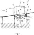
- FIG. 1 has a turbomachine 1, in particular a gas turbine or a compressor, a stator 2 and a rotor 3.
- the stator 2 may be formed, for example, as a guide blade 4.
- a blade 5 can be arranged in the usual manner.
- at least one sealing device 6 is arranged between the stator 2 and the rotor 3. The sealing device 6 extends in the axial direction of the turbomachine 1.
- the sealing device 6 has a honeycomb-shaped and radially stepped sealing contour 8 with in the direction of the rotor 3 back and forth areas 9 and 10 (see also Fig. 2 ).
- a plurality of sealing fins 11 projecting in the direction of the stator 2 are arranged, which respectively engage in adjacent, recessed regions 10 of the stator-side sealing contour 8.
- at least one additional fin 12 projecting in the direction of the stator 2 is additionally provided on the rotor side, which is positioned between two adjacent sealing fins 11 arranged on the rotor side and faces a projecting region 9 of the stator-side sealing contour 8.
- so-called additional fins 12 are additionally arranged which abut against the projecting regions 9 of the sealing contour 8 or even dig into them.
- Both the sealing fins 11 and the additional fins 12 are made of a wear-resistant compared to the sealing contour 8 material, so at a Contact between the fins 11, 12 and the sealing contour 8, a removal of the sealing contour 8 takes place and the fins 11, 12 dig into the sealing contour 8, whereby the sealing effect of the sealing device 6 is additionally improved.
- At least one additional fin 12 and / or a sealing fin 11 are arranged radially and axially inclined on the rotor 3 and on a heat shield 13 of the rotor 3.
- a degree of inclination of the at least one additional fin 12 or the at least one sealing fin 11 is approximately 25 ° -35 ° with respect to a radial perpendicular to the axis of the turbomachine 1.
- the inclination of the sealing fins 11 and the additional fins 12 takes place in opposite to the main flow 7a Direction, whereby upstream and / or downstream of the respective fin 11, 12 can form a so-called.
- the reference character 7b designates the leakage flow between the stator 2 and the rotor 3.
- the sealing means 6 according to the Fig. 2a to d have over their entire axial extent a constant radial height, while a radial height of the sealing device 6 according to the Fig. 2e changed in the axial direction of the turbomachine 1.
- These sealing devices 6 are particularly suitable for cases in which the axial relative movement is greater than the radial. For this reason, all sealing devices 6 according to the Fig.
- sealing devices 6 according to the Fig. 1 and 2 is common that at least the sealing fins 11 each have a wedge-shaped cross-sectional profile in the circumferential direction and thereby taper, starting from their rotor-side connection up to a free end.
- This offers the advantage that a connection area on the rotor side is made stronger and therefore more loadable, while the free end of the sealing fin 11 is significantly lighter and thus causes lower centrifugal forces or centrifugal forces.
- stator-side, recessed portion 10 preferably has an axial longitudinal extent of about two to three times the height h of the sealing fin 11 shown in longitudinal section, while a stator Weger, projecting portion 9 an axial longitudinal extent of about 1 to 2.5 times the Height h, that is, has a width b shown in longitudinal section of 1 to 2.5 times h.
- a radial height of the sealing fin 11 is approximately 2 to 4 times greater than a radial height of the additional fin 12.
- the radial height of both the additional fin is oriented 12 and the sealing fin 11 to constructive requirements.
- Fig. 2a to c and 2e is a last projecting portion 9 'much narrower, that is formed with a much smaller axial longitudinal extent, while according to the Fig. 2b completely missing.
- combinations of sealing fins 11 and additional fins 12 optimized with respect to the sealing effect can be used, wherein the sealing fins 1 and / or the additional fins can preferably be inclined opposite to the main flow direction 7a.
Description
Die Erfindung betrifft eine Strömungsmaschine, insbesondere eine Gasturbine, mit einem Rotor und einem Stator sowie einer zwischen dem Rotor und dem Stator angeordneten axialen Dichteinrichtung, gemäß dem Oberbegriff des Anspruchs 1.The invention relates to a turbomachine, in particular a gas turbine, having a rotor and a stator and an axial sealing device arranged between the rotor and the stator, according to the preamble of claim 1.
Um einem möglichst hohen Wirkungsgrad bei modernen Strömungsmaschinen, insbesondere bei Gasturbinen oder Verdichtern, erzeugen zu können, ist es wünschenswert, die Strömungsmaschine wirkungsvoll abzudichten und dadurch einen Verlust von die Strömungsmaschine antreibenden Heißgasen ebenso zu vermeiden wir einen Einbruch von Kühlgasen, welche die Temperatur innerhalb der Strömungsmaschine herabsetzen und dadurch den Wirkungsgrad negativ beeinflussen. Ein besonderes Problem bei der Abdichtung derartiger Strömungsmaschinen tritt insbesondere dann auf, wenn die Dichteinrichtung zwischen relativ zueinander bewegten Bauteilkomponenten angeordnet ist. Dies ist beispielsweise bei einer Dichteinrichtung der Fall, welche sich zwischen einem sich drehenden Rotor und einem relativ dazu feststehenden Stator angeordnet ist. Zusätzliche Relativbewegungen der sich gegenüberliegenden Dichteinrichtungskomponenten treten beim Übergang vom thermisch kalten Ruhezustand in den warmen Betriebszustand aufgrund der thermischen Ausdehnung und der mechanischen Belastung bei unterschiedlichen Materialeigenschaften der tragenden Teile auf.In order to be able to produce the highest possible efficiency in modern turbomachines, in particular in gas turbines or compressors, it is desirable to effectively seal the turbomachine and thereby avoid a loss of the turbomachine driving hot gases as well as a collapse of cooling gases, the temperature within the Reduce flow machine and thereby adversely affect the efficiency. A particular problem with the sealing of such turbomachines occurs in particular when the sealing device is arranged between relatively moving component components. This is for example the case with a sealing device which is arranged between a rotating rotor and a stator fixed relative thereto. Additional relative movements of the opposing sealing device components occur at the transition from the thermally cold resting state to the warm operating state due to the thermal expansion and the mechanical load at different material properties of the supporting parts.
Üblicherweise wird bei derartigen Dichteinrichtungen eine statorseitig radial gestufte Dichtkontur vorgesehen, welche in Richtung des Rotors vor- und zurückspringende Bereiche aufweist. Rotorseitig sind dabei mehrere in Richtung des Stators abstehende Dichtfinnen angeordnet, welche jeweils in benachbarte, zurückspringende Bereiche der statorseitigen Dichtkontur eingreifen. Durch die Dichtfinnen und die zugehörigen Dichtkonturen kann so eine sogenannte Labyrinthdichtung geschaffen werden, deren Dichtwirkung zusätzlich gesteigert werden kann, indem die Dichtkontur aus einem abtragungsfähigen Material und die Dichtfinnen aus einem abtragenden Material ausgebildet sind, so dass sich die Dichtfinnen beim Betrieb der Strömungsmaschine an die Dichtkonturen anlegen oder sogar in diese eingraben. Ein derartiges Eingraben bewirkt jedoch einen nicht zu unterschätzenden Verschleiß der Dichteinrichtung, wodurch diese ihre Dichtwirkung über die Zeit gesehen langsam wieder verliert.Usually, a stator-side radially stepped sealing contour is provided in the case of such sealing devices, which has regions that project back and forth in the direction of the rotor. On the rotor side, a plurality of sealing fins projecting in the direction of the stator are arranged, which respectively engage in adjacent, recessed regions of the stator-side sealing contour. By the sealing fins and the associated sealing contours so-called labyrinth seal can be created, the sealing effect can be further increased by the sealing contour of an ablatable material and the sealing fins are formed from an erosive material, so that the sealing fins during operation of the turbomachine to the Create sealing contours or even dig into them. However, such digging causes a not to be underestimated wear of the sealing device, whereby this slowly loses its sealing effect over time seen again.
Weitere Dichteinrichtungen gemäß dem Stand der Technik sind aus der
Neben einer Reduzierung des Wirkungsgrades der Strömungsmaschine hat eine schlechte Dichteigenschaft der Dichteinrichtung auch einen Heißgaseinbruch im Dichtbereich zur Folge, welcher einen Oxidationsprozess und damit auch eine Korrosion beschleunigt.In addition to a reduction in the efficiency of the turbomachine, a poor sealing property of the sealing device also results in a hot gas breakdown in the sealing region, which accelerates an oxidation process and thus also corrosion.
Hier setzt die Erfindung an. Die Erfindung, wie sie in den Ansprüchen gekennzeichnet ist, beschäftigt sich mit dem Problem, für eine Strömungsmaschine der gattungsgemäßen Art eine verbesserte oder zumindest eine andere Ausführungsform anzugeben, welche sich insbesondere durch eine verbesserte Dichtwirkung einer zugehörigen Dichteinrichtung auszeichnet.This is where the invention starts. The invention, as characterized in the claims, deals with the problem of providing an improved or at least another embodiment for a turbomachine of the generic type, which is characterized in particular by an improved sealing effect of an associated sealing device.
Dieses Problem wird erfindungsgemäß durch den Gegenstand des unabhängigen Anspruches 1 gelöst. Vorteilhafte Ausführungsformen sind Gegenstand der abhängigen Ansprüche.This problem is solved according to the invention by the subject matter of independent claim 1. Advantageous embodiments are the subject of the dependent claims.
Die Erfindung beruht auf dem allgemeinen Gedanken, bei einer Strömungsmaschine mit zumindest einer zwischen einem Rotor und einem Stator angeordneten axialen Dichteinrichtung zusätzlich zu den bereits üblicherweise vorhandenen Dichtfinnen sog. Zusatzfinnen vorzusehen, welche eine Labyrinthwirkung der Dichteinrichtung erhöhen und dadurch die Dichtwirkung der Dichteinrichtung verbessern. Dabei weist die Dichteinrichtung statorseitig eine radial gestufte Dichtkontur mit in Richtung des Rotors vor- und zurückspringenden Bereichen auf. In jeweils benachbarte, zurückspringende Bereiche der statorseitigen Dichtkontur greifen rotorseitig angeordnete und in Richtung des Stators abstehende Dichtfinnen ein, wodurch bereits eine gewisse Labyrinthdichtung bei herkömmlichen Dichteinrichtungen geschaffen wird. Erfindungsgemäß ist nun rotorseitig zumindest eine in Richtung des Stators abstehende Zusatzfinne vorgesehen, welche einem vorspringenden Bereich der statorseitigen Dichtkontur gegenüber liegt und zwischen zwei benachbarten, rotorseitig angeordneten Finnen positioniert ist. Somit wird die Gesamtzahl der Finnen erhöht und dadurch die Labyrinthwirkung der Dichteinrichtung verbessert. Die Zusatzfinnen können dabei in der gleichen Weise wie die Dichtfinnen ausgebildet sein und beispielsweise aus abtragendem Material bestehen, während die gegenüberliegende Dichtkontur aus abzutragendem Material besteht, so dass sich auch die Zusatzfinnen gegebenenfalls in eine Oberfläche der Dichtkontur eingraben können. Üblicherweise liegen sowohl die Zusatzfinnen als auch die Dichtfinnen an den gegenüberliegenden Bereichen der Dichtkontur an. Sowohl die Zusatzfinnen als auch die Dichtfinnen sind dabei als in Umfangsrichtung des Rotors durchgehende Konturen ausgebildet, wodurch diese die Form eines vom Rotor abstehenden Kragens erhalten. Ebenfalls in Umfangsrichtung im wesentlichen gleichbleibend ist die statorseitige Dichtkontur aufgebaut, so dass die im axialen Längsschnitt radial vor- und zurückspringenden Bereiche der Dichtkontur ringförmig ausgebildet sind. Auf jeden Fall verbessert die Anordnung zumindest einer Zusatzfinne die Labyrinthwirkung und damit die Dichtwirkung der Dichteinrichtung erheblich.The invention is based on the general idea, in a turbomachine with at least one arranged between a rotor and a stator axial sealing device in addition to the already commonly existing sealing fins so-called. Additional fins provide, which increase a labyrinth effect of the sealing device and thereby improve the sealing effect of the sealing device. In this case, the sealing device on the stator side has a radially stepped sealing contour with regions projecting back and forth in the direction of the rotor. In each adjacent, recessed areas of the stator-side sealing contour engage on the rotor side and projecting in the direction of the stator sealing fins, which already a certain labyrinth seal is provided in conventional sealing devices. According to the invention, at least one additional fin protruding in the direction of the stator is provided on the rotor side, which lies opposite a projecting region of the stator-side sealing contour and is positioned between two adjacent fins arranged on the rotor side. Thus, the total number of fins is increased, thereby improving the labyrinth effect of the sealing device. The additional fins can in the same way as the sealing fins be formed and, for example, consist of erosive material, while the opposite sealing contour consists of abzutragendem material, so that optionally the additional fins may possibly dig into a surface of the sealing contour. Usually, both the additional fins and the sealing fins abut against the opposite regions of the sealing contour. Both the additional fins and the sealing fins are formed as continuous contours in the circumferential direction of the rotor, whereby they receive the shape of a projecting collar of the rotor. The stator-side sealing contour is also constructed substantially uniformly in the circumferential direction so that the regions of the sealing contour projecting radially back and forth in the axial longitudinal section are annular. In any case, the arrangement of at least one additional fin substantially improves the labyrinth effect and thus the sealing effect of the sealing device.
Zweckmäßig sind zumindest eine Zusatzfinne und/oder eine Dichtfinne radial und axial geneigt am Rotor bzw. an einem rotorseitigen Hitzeschutzschild angeordnet. Eine Neigung in zur Hauptströmung entgegengesetzter Richtung der Dichtfinne bzw. der Zusatzfinne verstärkt dabei eine in Strömungsrichtung stromauf und stromab der jeweiligen Finne gelegene Stauströmung, bzw. einen sog. Totwasserbereich, welcher der Strömung entgegenwirkt und dadurch die Dichtwirkung der Dichteinrichtung verbessert. Gleichzeitig ist denkbar, dass bei hohen Rotationsgeschwindigkeiten sich die geneigten Finnen aufgrund der Fliehkräfte radial nach außen verformen und dadurch an die gegenüberliegende Dichtkontur anlegen. Auch hier kann wiederum ein Eingraben der Finnen in der wabenförmigen Dichtstruktur erfolgen, wobei ein Abtrag von Material ausschließlich im Bereich der Dichtkontur erfolgen soll.Suitably, at least one additional fin and / or one sealing fin are arranged radially and axially inclined on the rotor or on a rotor-side heat shield. An inclination in the direction opposite to the main flow direction of the sealing fin or the additional fin amplifies a flow upstream and downstream of the respective fin located Stauströmung, or a so-called. Totwasserbereich, which counteracts the flow and thereby improves the sealing effect of the sealing device. At the same time it is conceivable that at high rotational speeds, the inclined fins deform radially outward due to the centrifugal forces and thereby create the opposite sealing contour. Here again, a burying of the fins can take place in the honeycomb-shaped sealing structure, wherein a removal of material should take place exclusively in the region of the sealing contour.
Bei einer weiteren vorteilhaften Ausführungsform der erfindungsgemäßen Lösung weisen die Dichtfinnen und/oder die Zusatzfinne in Umfangsrichtung jeweils ein keilförmiges Querschnittsprofil auf. Ein derartiges keilförmiges Querschnittsprofil schafft eine breite Anbindungsbasis an den Rotor und dadurch eine zuverlässige Verbindung der Finne mit dem Rotor und gleichzeitig eine gewichtsoptimierte Finne, da sich diese radial nach außen verjüngt. Dies ist insbesondere für das Angreifen von Fliehkräften günstig, da eine im Querschnitt gleichbleibende Finne deutlich größere Fliehkräfte an ihrem freien Ende erzeugen würde, was eine deutlich größere Belastung des Anbindungsbereichs der Finne an den Rotor bzw. an einem Hitzeschutzschild des Rotors verursacht.
Weitere wichtige Merkmale und Vorteile der erfindungsgemäßen Strömungsmaschine ergeben sich aus den Unteransprüchen, aus den Zeichnungen und aus der zugehörigen Figurenbeschreibung anhand der Zeichnungen.In a further advantageous embodiment of the solution according to the invention, the sealing fins and / or the additional fin in the circumferential direction each one wedge-shaped cross-sectional profile. Such a wedge-shaped cross-sectional profile provides a wide connection base to the rotor and thereby a reliable connection of the fin with the rotor and at the same time a weight-optimized fin, as it tapers radially outward. This is particularly favorable for attacking centrifugal forces, since a cross-sectionally uniform fin would produce significantly greater centrifugal forces at its free end, which causes a significantly greater load on the connection region of the fin to the rotor or on a heat shield of the rotor.
Other important features and advantages of the turbomachine according to the invention will become apparent from the subclaims, from the drawings and from the associated description of the figures with reference to the drawings.
Bevorzugte Ausführungsbeispiele der Erfindung sind in den Zeichnungen dargestellt und werden in der nachfolgenden Beschreibung näher erläutert, wobei sich gleiche Bezugszeichen auf gleiche oder ähnliche oder funktional gleiche Komponenten beziehen.Preferred embodiments of the invention are illustrated in the drawings and will be described in more detail in the following description, wherein like reference numerals refer to the same or similar or functionally identical components.
Es zeigen dabei, jeweils schematisch,
- Fig. 1
- eine axiale Schnittdarstellung für eine Strömungsmaschine im Bereich einer zwischen einem Stator und einem Rotor gelegenen Dichteinrichtung,
- Fig. 2 a bis e
- unterschiedliche Ausführungsformen der erfindungsgemäßen Dichteinrichtung.
- Fig. 1
- an axial sectional view of a turbomachine in the region of a located between a stator and a rotor sealing device,
- Fig. 2 a to e
- different embodiments of the sealing device according to the invention.
Entsprechend
Um den Wirkungsgrad der Strömungsmaschine 1 möglichst hoch zu halten und andererseits Oxidationsprozesse durch einen Heißgaseinbruch zu minimieren, ist zwischen dem Stator 2 und dem Rotor 3 zumindest eine Dichteinrichtung 6 angeordnet. Die Dichteinrichtung 6 verläuft dabei in axialer Richtung der Strömungsmaschine 1. Statorseitig weist die Dichteinrichtung 6 eine honigwabenartig ausgebildete und radial gestufte Dichtkontur 8 mit in Richtung des Rotors 3 vor- und zurückspringenden Bereichen 9 und 10 auf (vgl. auch
In order to keep the efficiency of the turbomachine 1 as high as possible and, on the other hand, to minimize oxidation processes by means of a hot gas collapse, at least one
Die Dichtfinnen 11 bewirken zusammen mit der radial gestuften Dichtkontur 8 eine Labyrinthdichtung, welche ein Eindringen von Heißgasen zumindest erschwert. Um die Labyrinthwirkung weiter erhöhen zu können, sind nun zusätzlich sog. Zusatzfinnen 12 angeordnet, welche an den vorspringenden Bereichen 9 der Dichtkontur 8 anliegen oder sich sogar in diese eingraben. Sowohl die Dichtfinnen 11 als auch die Zusatzfinnen 12 sind dabei aus einem im Vergleich zur Dichtkontur 8 verschleißbeständigerem Material, sodass bei einer Berührung zwischen den Finnen 11, 12 und der Dichtkontur 8 ein Abtrag der Dichtkontur 8 erfolgt und sich die Finnen 11, 12 in die Dichtkontur 8 eingraben, wodurch die Dichtwirkung der Dichteinrichtung 6 zusätzlich verbessert wird.The sealing
Wie den
In den
Diese Dichteinrichtungen 6 sind besonders geeignet für Fälle, in denen die axiale Relativbewegung größer ist als die radiale. Aus diesem Grund ist allen Dichteinrichtungen 6 gemäß den
In the
These sealing
Ebenfalls allen Dichteinrichtungen 6 gemäß den
Selbstverständlich hängt eine Größe sowohl der Finnen 11, 12 als auch der vorspringenden und zurückspringenden Bereiche 9, 10 der Dichtkontur 8 von konstruktiven Erfordernissen ab, wobei die beste Dichtwirkung erzielt wird, wenn die verschiedenen Abmessungen bestimmte geometrischen Verhältnisse aufweisen. Der statorseitige, zurückspringende Bereich 10 weist dabei vorzugsweise eine axiale Längserstreckung von ca. zwei- bis dreimal der im Längsschnitt dargestellten Höhe h der Dichtfinne 11 auf, während ein statorseitiger, vorspringender Bereich 9 eine axiale Längserstreckung von ca. 1 bis 2,5 mal der Höhe h, also eine im Längsschnitt dargestellte Breite b von 1 bis 2,5 mal h aufweist.Of course, a size of both the
Ebenfalls den
In den
- 11
- Strömungsmaschineflow machine
- 22
- Statorstator
- 33
- Rotorrotor
- 44
- Leitschaufelvane
- 55
- Laufschaufelblade
- 66
- Dichteinrichtungsealing device
- 7a7a
- Hauptströmungmainstream
- 7b7b
- Leckageströmungleakage flow
- 88th
- Dichtkontursealing contour
- 99
- vorspringender Bereichprojecting area
- 1010
- zurückspringender Bereichreceding area
- 1111
- Dichtfinnesealing fin
- 1212
- Zusatzfinneadditional Finn
- 1313
- HitzeschutzschildHeat shield
- bb
- Breite, axiale LängserstreckungWidth, axial length
- hH
-
Höhe der Dichtfinne 11Height of the sealing
fin 11
Claims (5)
- Turbo machine (1), in particular a gas turbine,- with a stator (2) and a rotor (3) and an axial sealing device (6) arranged between the stator (2) and the rotor (3),- wherein the sealing device (6) on the stator side has a radially stepped sealing contour (8) with protruding and recessed regions (9, 10) in the direction of the rotor (3),- wherein on the rotor side, several sealing fins (11) are provided which protrude in the direction of the stator (2) and each engage in adjacent recessed regions (10) of the sealing contour (8) on the stator side,- wherein on the rotor side, at least one additional fin (12) is provided which protrudes in the direction of the stator (2) and is positioned between two adjacent sealing fins (11) arranged on the rotor side, and lies opposite a protruding region (9) of the stator-side sealing contour (8),- wherein a stator-side recessed region (10) is wider than a stator-side protruding region (9),- wherein the radial height (h) of the sealing fin (11) is approximately 2 to 4 times greater than a radial height of the additional fin (12),characterised in that
at least one additional fin (12) and/or sealing fin (11) is arranged radially and axially sloping on the rotor (3), and
that a slope angle of the at least one additional fin (12) and/or at least one sealing fin (11) is around 25° to 35°. - Turbo machine according to claim 1, characterised in that the at least one additional fin (12) and/or the at least one sealing fin (11) is arranged sloping in a direction opposite the main flow direction (7a).
- Turbo machine according to one of claims 1 or 2, characterised in that an axial distance between two protruding or recessed regions (9, 10) on the stator side is approximately twice as great as a radial height of the sealing fin (11).
- Turbo machine according to any of claims 1 to 3, characterised in that a stator-side recessed region (10) has an axial longitudinal extension of around two to three times a radial height (h) of the sealing fin (11), whereas a stator-side protruding region (9) has an axial longitudinal extension of around 1 to 2.5 times the radial height (h).
- Turbo machine according to any of claims 1 to 4, characterised in that the sealing fins (11) each have a wedge-shaped cross-sectional profile in the circumferential direction.
Applications Claiming Priority (1)
| Application Number | Priority Date | Filing Date | Title |
|---|---|---|---|
| CH13592006 | 2006-08-25 |
Publications (2)
| Publication Number | Publication Date |
|---|---|
| EP1898054A1 EP1898054A1 (en) | 2008-03-12 |
| EP1898054B1 true EP1898054B1 (en) | 2018-05-30 |
Family
ID=37441281
Family Applications (1)
| Application Number | Title | Priority Date | Filing Date |
|---|---|---|---|
| EP07114082.6A Active EP1898054B1 (en) | 2006-08-25 | 2007-08-09 | Gas turbine |
Country Status (2)
| Country | Link |
|---|---|
| US (1) | US8182211B2 (en) |
| EP (1) | EP1898054B1 (en) |
Families Citing this family (14)
| Publication number | Priority date | Publication date | Assignee | Title |
|---|---|---|---|---|
| US8376697B2 (en) * | 2008-09-25 | 2013-02-19 | Siemens Energy, Inc. | Gas turbine sealing apparatus |
| US8221062B2 (en) * | 2009-01-14 | 2012-07-17 | General Electric Company | Device and system for reducing secondary air flow in a gas turbine |
| US8561997B2 (en) * | 2010-01-05 | 2013-10-22 | General Electric Company | Adverse pressure gradient seal mechanism |
| US8845284B2 (en) | 2010-07-02 | 2014-09-30 | General Electric Company | Apparatus and system for sealing a turbine rotor |
| US8434766B2 (en) * | 2010-08-18 | 2013-05-07 | General Electric Company | Turbine engine seals |
| GB2492546A (en) * | 2011-07-04 | 2013-01-09 | Alstom Technology Ltd | A labyrinth seal for an axial fluid flow turbomachine |
| US8864453B2 (en) | 2012-01-20 | 2014-10-21 | General Electric Company | Near flow path seal for a turbomachine |
| US9080456B2 (en) | 2012-01-20 | 2015-07-14 | General Electric Company | Near flow path seal with axially flexible arms |
| US20130186103A1 (en) * | 2012-01-20 | 2013-07-25 | General Electric Company | Near flow path seal for a turbomachine |
| JP2014020509A (en) * | 2012-07-20 | 2014-02-03 | Toshiba Corp | Seal device, axial flow turbine, and power-generating plant |
| US10036278B2 (en) * | 2014-04-11 | 2018-07-31 | United Technologies Corporation | High pressure compressor thermal shield apparatus and system |
| JP6601677B2 (en) * | 2016-02-16 | 2019-11-06 | 三菱日立パワーシステムズ株式会社 | Sealing device and rotating machine |
| EP3318724A1 (en) * | 2016-11-04 | 2018-05-09 | Siemens Aktiengesellschaft | Sealing segment of a rotor and rotor |
| CN112671124B (en) * | 2020-12-26 | 2023-01-13 | 山东双华易驱智能制造研究院有限公司 | Motor inner stator and motor |
Citations (1)
| Publication number | Priority date | Publication date | Assignee | Title |
|---|---|---|---|---|
| EP0894947A2 (en) * | 1997-07-30 | 1999-02-03 | Mitsubishi Heavy Industries, Ltd. | Gas turbine interstage seal |
Family Cites Families (9)
| Publication number | Priority date | Publication date | Assignee | Title |
|---|---|---|---|---|
| DE668667C (en) * | 1938-12-08 | Oerlikon Maschf | Device to reduce steam losses in labyrinth seals for rotating shafts | |
| US1708044A (en) * | 1923-09-12 | 1929-04-09 | Westinghouse Electric & Mfg Co | Labyrinth-gland packing |
| US3251601A (en) * | 1963-03-20 | 1966-05-17 | Gen Motors Corp | Labyrinth seal |
| US4103899A (en) * | 1975-10-01 | 1978-08-01 | United Technologies Corporation | Rotary seal with pressurized air directed at fluid approaching the seal |
| US5029876A (en) * | 1988-12-14 | 1991-07-09 | General Electric Company | Labyrinth seal system |
| EP0799973B1 (en) * | 1996-04-01 | 2002-07-03 | Alstom | Wall contour for an axial turbomachine |
| US5961279A (en) * | 1996-05-31 | 1999-10-05 | Atlantic Richfield Company | Turbine power plant having minimal-contact brush seal augmented labyrinth seal |
| DE19940525A1 (en) * | 1999-08-26 | 2001-03-01 | Asea Brown Boveri | Heat accumulation unit for a rotor arrangement |
| US20040239040A1 (en) * | 2003-05-29 | 2004-12-02 | Burdgick Steven Sebastian | Nozzle interstage seal for steam turbines |
-
2007
- 2007-08-09 EP EP07114082.6A patent/EP1898054B1/en active Active
- 2007-08-20 US US11/841,333 patent/US8182211B2/en not_active Expired - Fee Related
Patent Citations (1)
| Publication number | Priority date | Publication date | Assignee | Title |
|---|---|---|---|---|
| EP0894947A2 (en) * | 1997-07-30 | 1999-02-03 | Mitsubishi Heavy Industries, Ltd. | Gas turbine interstage seal |
Also Published As
| Publication number | Publication date |
|---|---|
| US20080050233A1 (en) | 2008-02-28 |
| EP1898054A1 (en) | 2008-03-12 |
| US8182211B2 (en) | 2012-05-22 |
Similar Documents
| Publication | Publication Date | Title |
|---|---|---|
| EP1898054B1 (en) | Gas turbine | |
| EP1320662B1 (en) | Seal system | |
| DE10210866C5 (en) | Guide vane mounting in a flow channel of an aircraft gas turbine | |
| EP2320030B1 (en) | Rotor and rotor blade for an axial turbomachine | |
| DE112016003244T5 (en) | Cover for axial fan assembly | |
| EP3051068A1 (en) | Guide blade ring for a flow engine and additive manufacturing method | |
| EP1293644A1 (en) | Nozzle vanes support and heat accumulation segment | |
| EP2478186B1 (en) | Rotor of a turbomachine | |
| CH707459A2 (en) | Internal cooling structure of a turbine blade. | |
| CH697747B1 (en) | Gas turbine. | |
| EP1653049B1 (en) | Vane ring assembly for gas turbines and method to modify the same | |
| DE102007050916A1 (en) | Stator arrangement for compressor of fluid conveying arrangement in gas turbine engine, has radial passage conduit formed in part of stator ring segment, where radial passage conduit is arranged adjacent to stator blade passage conduit | |
| EP2092164B1 (en) | Turbomachine, particularly a gas turbine | |
| EP3412875A2 (en) | Running-in structure for a turbomachine and method for producing a running-in structure | |
| EP3324002A1 (en) | Axial turbomachine and sealing system for an axial turbomachine | |
| EP2647796A1 (en) | Seal system for a turbo engine | |
| EP3287608B1 (en) | Internal ring for a guide- blade rim of a turbomachine | |
| EP3287611A1 (en) | Gas turbine and method of attaching a turbine nozzle guide vane segment of a gas turbine | |
| EP3379037B1 (en) | Seal on the inner ring of a guide blade assembly | |
| EP2410131A2 (en) | Rotor of a turbomachine | |
| EP3263838A1 (en) | Turbine blade having internal cooling passage | |
| DE602004006035T2 (en) | Cooling device for turbine disks | |
| EP3109520B1 (en) | Seal carrier, guide blade assembly and fluid flow engine | |
| EP2196628A1 (en) | Lead rotor holder | |
| DE102009007664A1 (en) | Sealing device on the blade shank of a rotor stage of an axial flow machine |
Legal Events
| Date | Code | Title | Description |
|---|---|---|---|
| PUAI | Public reference made under article 153(3) epc to a published international application that has entered the european phase |
Free format text: ORIGINAL CODE: 0009012 |
|
| AK | Designated contracting states |
Kind code of ref document: A1 Designated state(s): AT BE BG CH CY CZ DE DK EE ES FI FR GB GR HU IE IS IT LI LT LU LV MC MT NL PL PT RO SE SI SK TR |
|
| AX | Request for extension of the european patent |
Extension state: AL BA HR MK YU |
|
| 17P | Request for examination filed |
Effective date: 20080904 |
|
| AKX | Designation fees paid |
Designated state(s): AT BE BG CH CY CZ DE DK EE ES FI FR GB GR HU IE IS IT LI LT LU LV MC MT NL PL PT RO SE SI SK TR |
|
| 17Q | First examination report despatched |
Effective date: 20150120 |
|
| RAP1 | Party data changed (applicant data changed or rights of an application transferred) |
Owner name: GENERAL ELECTRIC TECHNOLOGY GMBH |
|
| RAP1 | Party data changed (applicant data changed or rights of an application transferred) |
Owner name: ANSALDO ENERGIA IP UK LIMITED |
|
| GRAP | Despatch of communication of intention to grant a patent |
Free format text: ORIGINAL CODE: EPIDOSNIGR1 |
|
| INTG | Intention to grant announced |
Effective date: 20171214 |
|
| GRAS | Grant fee paid |
Free format text: ORIGINAL CODE: EPIDOSNIGR3 |
|
| GRAA | (expected) grant |
Free format text: ORIGINAL CODE: 0009210 |
|
| AK | Designated contracting states |
Kind code of ref document: B1 Designated state(s): AT BE BG CH CY CZ DE DK EE ES FI FR GB GR HU IE IS IT LI LT LU LV MC MT NL PL PT RO SE SI SK TR |
|
| REG | Reference to a national code |
Ref country code: GB Ref legal event code: FG4D Free format text: NOT ENGLISH |
|
| REG | Reference to a national code |
Ref country code: CH Ref legal event code: EP |
|
| REG | Reference to a national code |
Ref country code: AT Ref legal event code: REF Ref document number: 1003800 Country of ref document: AT Kind code of ref document: T Effective date: 20180615 |
|
| REG | Reference to a national code |
Ref country code: DE Ref legal event code: R096 Ref document number: 502007016203 Country of ref document: DE |
|
| REG | Reference to a national code |
Ref country code: IE Ref legal event code: FG4D Free format text: LANGUAGE OF EP DOCUMENT: GERMAN |
|
| REG | Reference to a national code |
Ref country code: NL Ref legal event code: MP Effective date: 20180530 |
|
| REG | Reference to a national code |
Ref country code: LT Ref legal event code: MG4D |
|
| PG25 | Lapsed in a contracting state [announced via postgrant information from national office to epo] |
Ref country code: SE Free format text: LAPSE BECAUSE OF FAILURE TO SUBMIT A TRANSLATION OF THE DESCRIPTION OR TO PAY THE FEE WITHIN THE PRESCRIBED TIME-LIMIT Effective date: 20180530 Ref country code: CY Free format text: LAPSE BECAUSE OF FAILURE TO SUBMIT A TRANSLATION OF THE DESCRIPTION OR TO PAY THE FEE WITHIN THE PRESCRIBED TIME-LIMIT Effective date: 20180530 Ref country code: FI Free format text: LAPSE BECAUSE OF FAILURE TO SUBMIT A TRANSLATION OF THE DESCRIPTION OR TO PAY THE FEE WITHIN THE PRESCRIBED TIME-LIMIT Effective date: 20180530 Ref country code: BG Free format text: LAPSE BECAUSE OF FAILURE TO SUBMIT A TRANSLATION OF THE DESCRIPTION OR TO PAY THE FEE WITHIN THE PRESCRIBED TIME-LIMIT Effective date: 20180830 Ref country code: ES Free format text: LAPSE BECAUSE OF FAILURE TO SUBMIT A TRANSLATION OF THE DESCRIPTION OR TO PAY THE FEE WITHIN THE PRESCRIBED TIME-LIMIT Effective date: 20180530 Ref country code: LT Free format text: LAPSE BECAUSE OF FAILURE TO SUBMIT A TRANSLATION OF THE DESCRIPTION OR TO PAY THE FEE WITHIN THE PRESCRIBED TIME-LIMIT Effective date: 20180530 |
|
| PG25 | Lapsed in a contracting state [announced via postgrant information from national office to epo] |
Ref country code: LV Free format text: LAPSE BECAUSE OF FAILURE TO SUBMIT A TRANSLATION OF THE DESCRIPTION OR TO PAY THE FEE WITHIN THE PRESCRIBED TIME-LIMIT Effective date: 20180530 Ref country code: GR Free format text: LAPSE BECAUSE OF FAILURE TO SUBMIT A TRANSLATION OF THE DESCRIPTION OR TO PAY THE FEE WITHIN THE PRESCRIBED TIME-LIMIT Effective date: 20180831 |
|
| PG25 | Lapsed in a contracting state [announced via postgrant information from national office to epo] |
Ref country code: NL Free format text: LAPSE BECAUSE OF FAILURE TO SUBMIT A TRANSLATION OF THE DESCRIPTION OR TO PAY THE FEE WITHIN THE PRESCRIBED TIME-LIMIT Effective date: 20180530 |
|
| PG25 | Lapsed in a contracting state [announced via postgrant information from national office to epo] |
Ref country code: DK Free format text: LAPSE BECAUSE OF FAILURE TO SUBMIT A TRANSLATION OF THE DESCRIPTION OR TO PAY THE FEE WITHIN THE PRESCRIBED TIME-LIMIT Effective date: 20180530 Ref country code: CZ Free format text: LAPSE BECAUSE OF FAILURE TO SUBMIT A TRANSLATION OF THE DESCRIPTION OR TO PAY THE FEE WITHIN THE PRESCRIBED TIME-LIMIT Effective date: 20180530 Ref country code: RO Free format text: LAPSE BECAUSE OF FAILURE TO SUBMIT A TRANSLATION OF THE DESCRIPTION OR TO PAY THE FEE WITHIN THE PRESCRIBED TIME-LIMIT Effective date: 20180530 Ref country code: EE Free format text: LAPSE BECAUSE OF FAILURE TO SUBMIT A TRANSLATION OF THE DESCRIPTION OR TO PAY THE FEE WITHIN THE PRESCRIBED TIME-LIMIT Effective date: 20180530 Ref country code: PL Free format text: LAPSE BECAUSE OF FAILURE TO SUBMIT A TRANSLATION OF THE DESCRIPTION OR TO PAY THE FEE WITHIN THE PRESCRIBED TIME-LIMIT Effective date: 20180530 Ref country code: SK Free format text: LAPSE BECAUSE OF FAILURE TO SUBMIT A TRANSLATION OF THE DESCRIPTION OR TO PAY THE FEE WITHIN THE PRESCRIBED TIME-LIMIT Effective date: 20180530 |
|
| PG25 | Lapsed in a contracting state [announced via postgrant information from national office to epo] |
Ref country code: IT Free format text: LAPSE BECAUSE OF FAILURE TO SUBMIT A TRANSLATION OF THE DESCRIPTION OR TO PAY THE FEE WITHIN THE PRESCRIBED TIME-LIMIT Effective date: 20180530 |
|
| REG | Reference to a national code |
Ref country code: DE Ref legal event code: R097 Ref document number: 502007016203 Country of ref document: DE |
|
| PG25 | Lapsed in a contracting state [announced via postgrant information from national office to epo] |
Ref country code: MC Free format text: LAPSE BECAUSE OF FAILURE TO SUBMIT A TRANSLATION OF THE DESCRIPTION OR TO PAY THE FEE WITHIN THE PRESCRIBED TIME-LIMIT Effective date: 20180530 |
|
| REG | Reference to a national code |
Ref country code: CH Ref legal event code: PL |
|
| PLBE | No opposition filed within time limit |
Free format text: ORIGINAL CODE: 0009261 |
|
| STAA | Information on the status of an ep patent application or granted ep patent |
Free format text: STATUS: NO OPPOSITION FILED WITHIN TIME LIMIT |
|
| PG25 | Lapsed in a contracting state [announced via postgrant information from national office to epo] |
Ref country code: CH Free format text: LAPSE BECAUSE OF NON-PAYMENT OF DUE FEES Effective date: 20180831 Ref country code: LU Free format text: LAPSE BECAUSE OF NON-PAYMENT OF DUE FEES Effective date: 20180809 Ref country code: LI Free format text: LAPSE BECAUSE OF NON-PAYMENT OF DUE FEES Effective date: 20180831 |
|
| 26N | No opposition filed |
Effective date: 20190301 |
|
| REG | Reference to a national code |
Ref country code: BE Ref legal event code: MM Effective date: 20180831 |
|
| REG | Reference to a national code |
Ref country code: IE Ref legal event code: MM4A |
|
| PG25 | Lapsed in a contracting state [announced via postgrant information from national office to epo] |
Ref country code: SI Free format text: LAPSE BECAUSE OF FAILURE TO SUBMIT A TRANSLATION OF THE DESCRIPTION OR TO PAY THE FEE WITHIN THE PRESCRIBED TIME-LIMIT Effective date: 20180530 |
|
| PG25 | Lapsed in a contracting state [announced via postgrant information from national office to epo] |
Ref country code: IE Free format text: LAPSE BECAUSE OF NON-PAYMENT OF DUE FEES Effective date: 20180809 |
|
| PG25 | Lapsed in a contracting state [announced via postgrant information from national office to epo] |
Ref country code: BE Free format text: LAPSE BECAUSE OF NON-PAYMENT OF DUE FEES Effective date: 20180831 Ref country code: FR Free format text: LAPSE BECAUSE OF NON-PAYMENT OF DUE FEES Effective date: 20180831 |
|
| REG | Reference to a national code |
Ref country code: AT Ref legal event code: MM01 Ref document number: 1003800 Country of ref document: AT Kind code of ref document: T Effective date: 20180809 |
|
| PG25 | Lapsed in a contracting state [announced via postgrant information from national office to epo] |
Ref country code: AT Free format text: LAPSE BECAUSE OF NON-PAYMENT OF DUE FEES Effective date: 20180809 |
|
| PG25 | Lapsed in a contracting state [announced via postgrant information from national office to epo] |
Ref country code: MT Free format text: LAPSE BECAUSE OF FAILURE TO SUBMIT A TRANSLATION OF THE DESCRIPTION OR TO PAY THE FEE WITHIN THE PRESCRIBED TIME-LIMIT Effective date: 20180530 |
|
| PG25 | Lapsed in a contracting state [announced via postgrant information from national office to epo] |
Ref country code: TR Free format text: LAPSE BECAUSE OF FAILURE TO SUBMIT A TRANSLATION OF THE DESCRIPTION OR TO PAY THE FEE WITHIN THE PRESCRIBED TIME-LIMIT Effective date: 20180530 |
|
| PG25 | Lapsed in a contracting state [announced via postgrant information from national office to epo] |
Ref country code: HU Free format text: LAPSE BECAUSE OF FAILURE TO SUBMIT A TRANSLATION OF THE DESCRIPTION OR TO PAY THE FEE WITHIN THE PRESCRIBED TIME-LIMIT; INVALID AB INITIO Effective date: 20070809 Ref country code: PT Free format text: LAPSE BECAUSE OF FAILURE TO SUBMIT A TRANSLATION OF THE DESCRIPTION OR TO PAY THE FEE WITHIN THE PRESCRIBED TIME-LIMIT Effective date: 20180530 |
|
| PG25 | Lapsed in a contracting state [announced via postgrant information from national office to epo] |
Ref country code: IS Free format text: LAPSE BECAUSE OF FAILURE TO SUBMIT A TRANSLATION OF THE DESCRIPTION OR TO PAY THE FEE WITHIN THE PRESCRIBED TIME-LIMIT Effective date: 20180930 |
|
| PGFP | Annual fee paid to national office [announced via postgrant information from national office to epo] |
Ref country code: GB Payment date: 20231220 Year of fee payment: 17 |
|
| PGFP | Annual fee paid to national office [announced via postgrant information from national office to epo] |
Ref country code: DE Payment date: 20231214 Year of fee payment: 17 |