EP1598277B1 - Durchlaufsiegelgerät - Google Patents
Durchlaufsiegelgerät Download PDFInfo
- Publication number
- EP1598277B1 EP1598277B1 EP05010103A EP05010103A EP1598277B1 EP 1598277 B1 EP1598277 B1 EP 1598277B1 EP 05010103 A EP05010103 A EP 05010103A EP 05010103 A EP05010103 A EP 05010103A EP 1598277 B1 EP1598277 B1 EP 1598277B1
- Authority
- EP
- European Patent Office
- Prior art keywords
- ink ribbon
- guide
- printing head
- device housing
- spools
- Prior art date
- Legal status (The legal status is an assumption and is not a legal conclusion. Google has not performed a legal analysis and makes no representation as to the accuracy of the status listed.)
- Expired - Lifetime
Links
Images

Classifications
-
- B—PERFORMING OPERATIONS; TRANSPORTING
- B65—CONVEYING; PACKING; STORING; HANDLING THIN OR FILAMENTARY MATERIAL
- B65B—MACHINES, APPARATUS OR DEVICES FOR, OR METHODS OF, PACKAGING ARTICLES OR MATERIALS; UNPACKING
- B65B51/00—Devices for, or methods of, sealing or securing package folds or closures; Devices for gathering or twisting wrappers, or necks of bags
- B65B51/10—Applying or generating heat or pressure or combinations thereof
- B65B51/16—Applying or generating heat or pressure or combinations thereof by rotary members
-
- B—PERFORMING OPERATIONS; TRANSPORTING
- B29—WORKING OF PLASTICS; WORKING OF SUBSTANCES IN A PLASTIC STATE IN GENERAL
- B29C—SHAPING OR JOINING OF PLASTICS; SHAPING OF MATERIAL IN A PLASTIC STATE, NOT OTHERWISE PROVIDED FOR; AFTER-TREATMENT OF THE SHAPED PRODUCTS, e.g. REPAIRING
- B29C65/00—Joining or sealing of preformed parts, e.g. welding of plastics materials; Apparatus therefor
- B29C65/02—Joining or sealing of preformed parts, e.g. welding of plastics materials; Apparatus therefor by heating, with or without pressure
-
- B—PERFORMING OPERATIONS; TRANSPORTING
- B29—WORKING OF PLASTICS; WORKING OF SUBSTANCES IN A PLASTIC STATE IN GENERAL
- B29C—SHAPING OR JOINING OF PLASTICS; SHAPING OF MATERIAL IN A PLASTIC STATE, NOT OTHERWISE PROVIDED FOR; AFTER-TREATMENT OF THE SHAPED PRODUCTS, e.g. REPAIRING
- B29C66/00—General aspects of processes or apparatus for joining preformed parts
- B29C66/01—General aspects dealing with the joint area or with the area to be joined
- B29C66/05—Particular design of joint configurations
- B29C66/10—Particular design of joint configurations particular design of the joint cross-sections
- B29C66/11—Joint cross-sections comprising a single joint-segment, i.e. one of the parts to be joined comprising a single joint-segment in the joint cross-section
- B29C66/112—Single lapped joints
- B29C66/1122—Single lap to lap joints, i.e. overlap joints
-
- B—PERFORMING OPERATIONS; TRANSPORTING
- B29—WORKING OF PLASTICS; WORKING OF SUBSTANCES IN A PLASTIC STATE IN GENERAL
- B29C—SHAPING OR JOINING OF PLASTICS; SHAPING OF MATERIAL IN A PLASTIC STATE, NOT OTHERWISE PROVIDED FOR; AFTER-TREATMENT OF THE SHAPED PRODUCTS, e.g. REPAIRING
- B29C66/00—General aspects of processes or apparatus for joining preformed parts
- B29C66/01—General aspects dealing with the joint area or with the area to be joined
- B29C66/05—Particular design of joint configurations
- B29C66/306—Applying a mark during joining
-
- B—PERFORMING OPERATIONS; TRANSPORTING
- B29—WORKING OF PLASTICS; WORKING OF SUBSTANCES IN A PLASTIC STATE IN GENERAL
- B29C—SHAPING OR JOINING OF PLASTICS; SHAPING OF MATERIAL IN A PLASTIC STATE, NOT OTHERWISE PROVIDED FOR; AFTER-TREATMENT OF THE SHAPED PRODUCTS, e.g. REPAIRING
- B29C66/00—General aspects of processes or apparatus for joining preformed parts
- B29C66/40—General aspects of joining substantially flat articles, e.g. plates, sheets or web-like materials; Making flat seams in tubular or hollow articles; Joining single elements to substantially flat surfaces
- B29C66/41—Joining substantially flat articles ; Making flat seams in tubular or hollow articles
- B29C66/43—Joining a relatively small portion of the surface of said articles
- B29C66/431—Joining the articles to themselves
- B29C66/4312—Joining the articles to themselves for making flat seams in tubular or hollow articles, e.g. transversal seams
- B29C66/43121—Closing the ends of tubular or hollow single articles, e.g. closing the ends of bags
-
- B—PERFORMING OPERATIONS; TRANSPORTING
- B41—PRINTING; LINING MACHINES; TYPEWRITERS; STAMPS
- B41J—TYPEWRITERS; SELECTIVE PRINTING MECHANISMS, i.e. MECHANISMS PRINTING OTHERWISE THAN FROM A FORME; CORRECTION OF TYPOGRAPHICAL ERRORS
- B41J2/00—Typewriters or selective printing mechanisms characterised by the printing or marking process for which they are designed
- B41J2/315—Typewriters or selective printing mechanisms characterised by the printing or marking process for which they are designed characterised by selective application of heat to a heat sensitive printing or impression-transfer material
- B41J2/32—Typewriters or selective printing mechanisms characterised by the printing or marking process for which they are designed characterised by selective application of heat to a heat sensitive printing or impression-transfer material using thermal heads
- B41J2/325—Typewriters or selective printing mechanisms characterised by the printing or marking process for which they are designed characterised by selective application of heat to a heat sensitive printing or impression-transfer material using thermal heads by selective transfer of ink from ink carrier, e.g. from ink ribbon or sheet
-
- B—PERFORMING OPERATIONS; TRANSPORTING
- B41—PRINTING; LINING MACHINES; TYPEWRITERS; STAMPS
- B41J—TYPEWRITERS; SELECTIVE PRINTING MECHANISMS, i.e. MECHANISMS PRINTING OTHERWISE THAN FROM A FORME; CORRECTION OF TYPOGRAPHICAL ERRORS
- B41J3/00—Typewriters or selective printing or marking mechanisms characterised by the purpose for which they are constructed
- B41J3/407—Typewriters or selective printing or marking mechanisms characterised by the purpose for which they are constructed for marking on special material
-
- B—PERFORMING OPERATIONS; TRANSPORTING
- B41—PRINTING; LINING MACHINES; TYPEWRITERS; STAMPS
- B41J—TYPEWRITERS; SELECTIVE PRINTING MECHANISMS, i.e. MECHANISMS PRINTING OTHERWISE THAN FROM A FORME; CORRECTION OF TYPOGRAPHICAL ERRORS
- B41J3/00—Typewriters or selective printing or marking mechanisms characterised by the purpose for which they are constructed
- B41J3/44—Typewriters or selective printing mechanisms having dual functions or combined with, or coupled to, apparatus performing other functions
-
- B—PERFORMING OPERATIONS; TRANSPORTING
- B29—WORKING OF PLASTICS; WORKING OF SUBSTANCES IN A PLASTIC STATE IN GENERAL
- B29C—SHAPING OR JOINING OF PLASTICS; SHAPING OF MATERIAL IN A PLASTIC STATE, NOT OTHERWISE PROVIDED FOR; AFTER-TREATMENT OF THE SHAPED PRODUCTS, e.g. REPAIRING
- B29C2795/00—Printing on articles made from plastics or substances in a plastic state
- B29C2795/007—Printing on articles made from plastics or substances in a plastic state after shaping
-
- B—PERFORMING OPERATIONS; TRANSPORTING
- B29—WORKING OF PLASTICS; WORKING OF SUBSTANCES IN A PLASTIC STATE IN GENERAL
- B29C—SHAPING OR JOINING OF PLASTICS; SHAPING OF MATERIAL IN A PLASTIC STATE, NOT OTHERWISE PROVIDED FOR; AFTER-TREATMENT OF THE SHAPED PRODUCTS, e.g. REPAIRING
- B29C65/00—Joining or sealing of preformed parts, e.g. welding of plastics materials; Apparatus therefor
- B29C65/02—Joining or sealing of preformed parts, e.g. welding of plastics materials; Apparatus therefor by heating, with or without pressure
- B29C65/18—Joining or sealing of preformed parts, e.g. welding of plastics materials; Apparatus therefor by heating, with or without pressure using heated tools
-
- B—PERFORMING OPERATIONS; TRANSPORTING
- B29—WORKING OF PLASTICS; WORKING OF SUBSTANCES IN A PLASTIC STATE IN GENERAL
- B29C—SHAPING OR JOINING OF PLASTICS; SHAPING OF MATERIAL IN A PLASTIC STATE, NOT OTHERWISE PROVIDED FOR; AFTER-TREATMENT OF THE SHAPED PRODUCTS, e.g. REPAIRING
- B29C65/00—Joining or sealing of preformed parts, e.g. welding of plastics materials; Apparatus therefor
- B29C65/78—Means for handling the parts to be joined, e.g. for making containers or hollow articles, e.g. means for handling sheets, plates, web-like materials, tubular articles, hollow articles or elements to be joined therewith; Means for discharging the joined articles from the joining apparatus
- B29C65/7858—Means for handling the parts to be joined, e.g. for making containers or hollow articles, e.g. means for handling sheets, plates, web-like materials, tubular articles, hollow articles or elements to be joined therewith; Means for discharging the joined articles from the joining apparatus characterised by the feeding movement of the parts to be joined
- B29C65/7861—In-line machines, i.e. feeding, joining and discharging are in one production line
- B29C65/787—In-line machines, i.e. feeding, joining and discharging are in one production line using conveyor belts or conveyor chains
- B29C65/7873—In-line machines, i.e. feeding, joining and discharging are in one production line using conveyor belts or conveyor chains using cooperating conveyor belts or cooperating conveyor chains
-
- B—PERFORMING OPERATIONS; TRANSPORTING
- B29—WORKING OF PLASTICS; WORKING OF SUBSTANCES IN A PLASTIC STATE IN GENERAL
- B29C—SHAPING OR JOINING OF PLASTICS; SHAPING OF MATERIAL IN A PLASTIC STATE, NOT OTHERWISE PROVIDED FOR; AFTER-TREATMENT OF THE SHAPED PRODUCTS, e.g. REPAIRING
- B29C66/00—General aspects of processes or apparatus for joining preformed parts
- B29C66/80—General aspects of machine operations or constructions and parts thereof
- B29C66/83—General aspects of machine operations or constructions and parts thereof characterised by the movement of the joining or pressing tools
- B29C66/834—General aspects of machine operations or constructions and parts thereof characterised by the movement of the joining or pressing tools moving with the parts to be joined
- B29C66/8341—Roller, cylinder or drum types; Band or belt types; Ball types
- B29C66/83421—Roller, cylinder or drum types; Band or belt types; Ball types band or belt types
- B29C66/83423—Roller, cylinder or drum types; Band or belt types; Ball types band or belt types cooperating bands or belts
-
- B—PERFORMING OPERATIONS; TRANSPORTING
- B29—WORKING OF PLASTICS; WORKING OF SUBSTANCES IN A PLASTIC STATE IN GENERAL
- B29C—SHAPING OR JOINING OF PLASTICS; SHAPING OF MATERIAL IN A PLASTIC STATE, NOT OTHERWISE PROVIDED FOR; AFTER-TREATMENT OF THE SHAPED PRODUCTS, e.g. REPAIRING
- B29C66/00—General aspects of processes or apparatus for joining preformed parts
- B29C66/80—General aspects of machine operations or constructions and parts thereof
- B29C66/84—Specific machine types or machines suitable for specific applications
-
- B—PERFORMING OPERATIONS; TRANSPORTING
- B29—WORKING OF PLASTICS; WORKING OF SUBSTANCES IN A PLASTIC STATE IN GENERAL
- B29C—SHAPING OR JOINING OF PLASTICS; SHAPING OF MATERIAL IN A PLASTIC STATE, NOT OTHERWISE PROVIDED FOR; AFTER-TREATMENT OF THE SHAPED PRODUCTS, e.g. REPAIRING
- B29C66/00—General aspects of processes or apparatus for joining preformed parts
- B29C66/90—Measuring or controlling the joining process
- B29C66/96—Measuring or controlling the joining process characterised by the method for implementing the controlling of the joining process
- B29C66/967—Measuring or controlling the joining process characterised by the method for implementing the controlling of the joining process involving special data inputs or special data outputs, e.g. for monitoring purposes
- B29C66/9674—Measuring or controlling the joining process characterised by the method for implementing the controlling of the joining process involving special data inputs or special data outputs, e.g. for monitoring purposes involving special data outputs, e.g. special data display means
-
- B—PERFORMING OPERATIONS; TRANSPORTING
- B29—WORKING OF PLASTICS; WORKING OF SUBSTANCES IN A PLASTIC STATE IN GENERAL
- B29L—INDEXING SCHEME ASSOCIATED WITH SUBCLASS B29C, RELATING TO PARTICULAR ARTICLES
- B29L2031/00—Other particular articles
- B29L2031/712—Containers; Packaging elements or accessories, Packages
- B29L2031/7128—Bags, sacks, sachets
Definitions
- the invention relates to a continuous sealing device for sealing the edges of openings filled with sterilized packaging bags made of weldable plastic film according to the preamble of the independent claim. 1
- through-flow sealing devices are so-called semi-automatic machines, in which the filled and sealed bags are manually applied and inserted by hand into the laterally open through-feed guide, in which further transport takes place by passage of two endless rolls between two sealing rolls while passing a film preheating. which seal the two adjacent opening edges of a bag together.
- This is followed by the printing of the sealing edge, for example, with content-specific data, by means of the in the end region of the flow guide in the device housing with arranged dot matrix printer.
- content-specific data are, for example, to understand the sterilization date, the expiration date, batch number, so-called BAR codes and the like. Data.
- thermal transfer printing certain, programmable thermal printer are known, but come, as far as known, in particular for label printing for use, as a separate device, the on a carrier tape with the same distance and supplied labels continuously with each entered Data are printed by thermal loading of the ink ribbon by means of so-called "dots".
- separate thermal transfer printing devices are also equipment of eg. Packing tables for the sterile packaging of interest here by means of the aforementioned continuous sealing devices, although the printed labels must be transferred to the sealing edges of the sealed packaging bag or whatever, after detachment from their carrier tape.
- Label tape and synchronous printing process, in a continuous flow is in the continuous sealing device according to the invention made sure that this synchronicity is guaranteed only for the actual printing on the sealing edge passing straight to the print head.
- a change to a gegf. desired other ink is to accomplish readily by changing the ribbon.
- a preferred, particularly advantageous embodiment which will be explained in more detail is that the spools are formed with their ink ribbon in the form of a replaceable cassette.
- the cassette enclosing the coils are connected by a web which leads tangentially away from the reels and leading to the ink ribbon, in which a pass-through window for the pressure-active part of the thermal print head is arranged.
- the device housing in the area of the printer and cartridge assembly is provided with a lockable access opening and also with an input keyboard for programming.
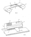
- the continuous sealing device is still and in a known manner with reference to the Fig.1,2 from a arranged in a flow guide 2 of the device welding tool 3 for Detection and welding or sealing of the opening edges R of each passing bag VB and from a arranged in the end of the flow guide 2 of the device housing 1 printing unit 4 for printing the sealed opening edges R.
- the to be sealed and to be printed bag VB are still left on Device created, detected by a transport device TE and further transported for sealing and printing.
- heaters and An horr- or sealing rollers are provided with the reference numerals H and A.
- the printing unit 4 connected to a sensor 7 is arranged above a ribbon 5 guided parallel to and directly above the pass-through guide 2, and the ink ribbon 5 is guided by take-off and package coils 6, 6 ', likewise arranged above the pass-through guide 2, between which the print head 4 'is arranged in the position of action to the ink ribbon 5.
- the printing unit 4 formed from a programmable thermal print head 4 'and designed as Siegelrandsensor sensor 7 in the pass guide 2 in front of the thermal print head 4' and connected to the thermal print head 4 'and the ribbon drive in controlling Wirktagen_ standing is, wherein the thermal print head 4 'with the thermal transfer ribbon 5 in relation to the plane of the flow guide 2 distanzein suit in the device housing 1 is arranged.
- the device housing 1 is provided on the operating side with a display 14 for displaying the respectively programmed pressure data.
- This via device control 12 (see Figure 2) connected to the ribbon drive sensor 7 ensures that for the incoming bag or sealing edge R an unused, new ribbon section is available, which adjoins the run-up, used-up section as close as possible ,
- the thermal print head 4 ' as mentioned above, with the thermal transfer ribbon 5 with respect to the plane of the flow guide 2 distanzein suit in the device housing 1 is arranged.
- This distance adjustability moves in the order of only millimeter fractions up to a few millimeters. This is not particularly illustrated and also not to explain special, since correspondingly constructive possibilities and elements are readily available.
- the aforesaid bobbins 6, 6 ' are formed with their thermal transfer ribbon 5 in the form of a replaceable cassette 8, the cassette parts 8' surrounding the bobbins 6, 6 'being separated by a tangent from the bobbins 6, 6'. starting and run-up ribbon 5 leading web 9 are connected, in which a penetration window 10 for the pressure-active part of the thermal print head 4 'is arranged.
- the device housing 1 is provided in the area of the printer and cassette arrangement with a closable access opening 11, as indicated by dashed lines in FIG.
- the device housing 1 is provided on the operator side with a programming panel 12, this programming panel 12 is preferably arranged with reference to Figure 4 as a separate accessory on the desk-like inclined front surface 13 of the device housing 1, which also also with the operator side a display 14 for displaying the respectively programmed current print data is provided.
Landscapes
- Engineering & Computer Science (AREA)
- Mechanical Engineering (AREA)
- Electronic Switches (AREA)
- Auxiliary Devices For And Details Of Packaging Control (AREA)
- Making Paper Articles (AREA)
- Package Closures (AREA)
- Impression-Transfer Materials And Handling Thereof (AREA)
Description
- Die Erfindung betrifft ein Durchlaufsiegelgerät zum Schweißversiegeln der Öffnungsränder von mit Sterilgut gefüllten Verpackungsbeuteln aus verschweißbarer Kunststofffolie gemäß Oberbegriff des unabhängigen Patentanspruches 1.
- Durchlaufsiegelgeräte sind bspw. nach dem
DE-A-296 10 976 U1 bekannt und sofern solche Geräte, wie einleitend angegeben, mit einem Drucker gemäßDE-A-200 19 799 U1 ausgestattet sind, handelt es sich bei diesen Druckern in Verbindung mit solchen speziellen Durchlaufsiegelgeräten, soweit bekannt, ausschließlich um sogenannte Nadeldruckwerke oder auch gemäß PATENT AB-STRACT OFJAPAN Nr. 2000128134 - Derartige Durchlaufsiegelgeräte haben sich hinsichtlich des Bedruckens der Beutelsiegelränder als verbesserbar erwiesen, d.h., das Durchlaufsiegelgerät soll besser und einfacher steuerbar sein, ein besseres Druckbild ergeben und auch variable Schriftgrößen und gewünschtenfalls auch den Druckübertrag von Graphikdarstellungen zulassen.
- Diese Aufgabe ist an Siegelgeräten der eingangs genannten Art nach der Erfindung durch die im Kennzeichen des unabhängigen Patentanspruches 1 angeführten Merkmale gelöst.
vorteilhafte Weiterbildungen und Ausführungsformen sind in den abhängigen Patentansprüchen 2 bis 6 erfaßt.
Die Maßgabe der Distanzeinstellbarkeit des Thermodruckkopfes macht einen solchen überhaupt im vorliegenden Zusammenhang erst einsetzbar und zwar mit Rücksicht darauf, daß beim Beutelversiegeln unterschiedlich starke Siegelränder vorliegen oder entstehen können. - Solche,für den sogenannten Thermotransferdruck bestimmte, programmierbare Thermodrucker sind zwar bekannt, kommen aber, soweit bekannt, insbesondere für den Etikettendruck zur Verwendung, und zwar als separate Geräte, wobei die auf einem Trägerband mit gleichem Abstand befindlichen und zugeführten Etiketten fortlaufend mit den jeweils eingegebenen Daten durch thermische Beaufschlagung des Farbbandes mittels sogenannter "dots" bedruckt werden. Solche separaten Thermotransfer-Druckgeräte sind auch schon Ausstattungsgegenstand von bspw. Packtischen für die hier interessierende Sterilgutverpackung mittels der vorerwähnten Durchlaufsiegelgeräte, wobei allerdings die bedruckten Etiketten nach Ablösung von ihrem Trägerband auf die Siegelränder der versiegelten Verpackungsbeutel oder was auch immer übertragen werden müssen.
Einer unmittelbaren Übertragung dieser Thermotransferdruckmethode, die zu hervorragenden und dauerhaft haltbaren Druckergebnissen auch auf Kunststofffolien führt, auf Durchlaufsiegelgeräte stand jedoch entgegen, daß es sich bei diesen Geräten, wie erwähnt, um sogenannte Halbautomaten handelt, bei denen also keine gleichmäßig kontinuierliche Zufuhr der zu bedruckenden Siegelränder zu verwirklichen ist. Abgesehen davon, war auch nicht ohne weiteres zu erwarten, daß sich das Thermotransfer-Druckverfahren erfolgreich auch dann anwenden läßt, wenn unter vorteilhafter Vermeidung einer Etikettenübertragung vom Siegelvorgang bereits erwärmte bzw. noch relativ warme Foliensiegelränder bedruckt werden sollen. - Unter einem programmierbaren Thermodruckkopf ist also ein Druckkopf zu verstehen, mit dem die auf dem Farbband auf der druckerabgewandten Seite befindliche, per Wärme und einem gewissen Druck übertragbare Farbe bei in Druckkontakt befindlichen und per Programm am Druckkopf eingestellten Lettern, Zahlen oder auch sonstige Darstellungen auf die Siegelrandfläche des betreffenden Beutels wiedergabegenau übertragen wird. Der auf die gewünschten Daten eingestellte Druckkopf bzw. dessen sogenannten, individuell zur Wirkung bringbaren "dots" bildet also ein einfach programmierbares Druckmedium, das unter Zwischenschaltung des Farbbandes per Thermostransfer die eingestellten Daten überträgt, die, da gewissermaßen eingebrannt, auch unverwischbar ihre Wiedergabe auf den Siegelrändern finden.
- Abgesehen von der mittels einer Eingabetastatur zu bewirkenden einfachen Programmierung dessen, was gedruckt werden soll, ist dabei das Gerät bzgl. des Weitertransportes des Farbbandes einfach zu steuern und zwar in Übereinstimmung mit einem in der Durchlaufführung ankommenden Siegelrand, welches Ankommen nicht in gleichmäßigen Abständen erfolgt, da ja die zu versiegelnden Beutel von Hand in das Siegelgerät eingegeben werden. Aus diesem Grunde ist in der Durchlaufführung vor dem Thermodruckkopf ein Siegelrandsensor angeordnet, der über die Gerätesteuerung mit dem Transportantrieb für das Thermofarbband verschaltet ist und gegf. geringfügig zeitversetzt den Thermotransfervorgang beginnen läßt.
Im Gegensatz zum bisher praktizierten Thermotransferdruckverfahren, das einen Synchronlauf von Farband, bspw. Etikettenband und dazu synchronen Druckvorgang verlangt, und zwar im kontinuierlichen Durchlauf, ist beim erfindungsgemäßen Durchlaufsiegelgerät dafür gesorgt, daß diese Synchronizität nur für den eigentlichen Druckvorgang am gerade den Druckkopf passierenden Siegelrand gewährleistet ist.
Ein Umstellen auf eine gegf. gewünschte andere Druckfarbe ist ohne weiteres durch Wechsel des Farbbandes zu bewerkstelligen. Um einen solchen Wechsel oder auch einen Austausch gegen ein neues Farbband so einfach wie möglich durchführen zu können, besteht eine bevorzugte, besonders vorteilhafte und im Einzelnen noch näher zu erläuternde Ausführungsform darin, daß die Spulen mit ihrem Farbband in Form einer auswechselbaren Kassette ausgebildet sind, deren die Spulen umschließenden Kassettenteile durch einen das tangential von den Spulen ab-und auflaufende Farbband führenden Steg verbunden sind, in dem ein Durchgriffsfenster für den druckaktiven Teil des Thermo-Druckkopfes angeordnet ist. - Mit Rücksicht auf die einfache Kassettenaustauschbarkeit ist schließlich das Gerätegehäuse im Bereich der Drucker- und Kassettenanordnung mit einer verschließbaren Zugriffsöffnung versehen und außerdem mit einer Eingabetastatur für die Programmierung.
- Das erfindungsgemäße Siegelgerät wird nachfolgend anhand der zeichnerischen Darstellung von Ausführungsbeispielen näher erläutert.
- Es zeigt schematisch
- Fig.1
- perspektivisch ein Ausführungsbeispiel des Durchlauf-Siegelgerätes;
- Fig.2
- schematisch einen Längsschnitt durch das Gerät;
- Fig.3
- perspektivisch eine Ausführungsform der Farbbandkassette und
- Fig.4
- perspektivisch eine bevorzugte Ausführungsform des Durchlauf-Siegelgerätes.
- Das Durchlaufsiegelgerät besteht nach wie vor und in bekannter Weise unter Verweis auf die Fig.1,2 aus einem in einer Durchlaufführung 2 des Gerätes angeordneten Schweißwerkzeug 3 zur Erfassung und Verschweißung bzw. Versiegelung der Öffnungsränder R des jeweils passierenden Beutels VB und aus einem im Endbereich der Durchlaufführung 2 des Gerätegehäuses 1 angeordneten Druckwerk 4 zum Bedrucken der versiegelten Öffnungsränder R. Die zu versiegelnden und zu bedruckenden Beutel VB werden dabei nach wie vor links am Gerät angelegt, von einer Transporteinrichtung TE erfaßt und zum Versiegeln und Bedrucken weitertransportiert. Dafür erforderliche Heizeinrichtungen und Andruck- bzw. Siegelrollen sind mit den Bezugszeichen H und A versehen. Das mit einem Sensor 7 verschaltete Druckwerk 4 ist dabei über einem parallel zur und unmittelbar über der Durchlaufführung 2 geführten Farbband 5 angeordnet, und das Farbband 5 ist von ebenfalls über der Durchlaufführung 2 angeordneten Ab- und Auflaufspulen 6,6' geführt, zwischen denen der Druckkopf 4' in Einwirkstellung zum Farbband 5 angeordnet ist.
- Für ein solches Durchlaufsiegelgerät ist nun wesentlich, daß das Druckwerk 4 aus einem programmierbaren Thermodruckkopf 4' gebildet und der als Siegelrandsensor ausgebildete Sensor 7 in der Durchlaufführung 2 vor dem Thermodruckkopf 4' angeordnet und mit dem Thermodruckkopf 4' und dem Farbbandantrieb in steuernder Wirkverbindung_ stehend verbunden ist, wobei der Thermodruckkopf 4' mit dem Thermotransfer-Farbband 5 in Bezug auf die Ebene der Durchlaufführung 2 distanzeinstellbar im Gerätegehäuse 1 angeordnet ist.
Zwecksmäßig ist dabei das Gerätegehäuse 1 bedienseitig mit einem Display 14 zur Darstellung der jeweils programmierten Druckdaten versehen.
Dieser via Gerätesteuerung 12 (siehe Fig.2) mit dem Farbbandantrieb verschaltete Sensor 7 sorgt dafür, daß für den ankommenden Beutel bzw. Siegelrand R ein unverbrauchter, neuer Farbbandabschnitt zur Verfügung steht, der sich an den vorgelaufenen, verbrauchten Abschnitt so dicht wie möglich anschließt.
Mit Rücksicht darauf, daß zum Einen beim Thermotransfer-Druckverfahren die zu bedruckende Fläche und das Farbband 5 synchron unter dem stationär angeordneten Thermodruckkopf 4' durchlaufen, wobei die temperierten und vorprogrammierten "dots" 11 des Druckkopfes mit der Durchlaufgeschwindigkeit zur Wirkung gebracht werden und wobei zum Anderen im Gegensatz zum Etikettendruck beim Beutelversiegeln unterschiedlich starke Siegelränder anfallen können und zu bedrucken sind, ist aber immer, und das ist wesentlich, der gleiche, relativ schwache Kontaktdruck für den Farbtransfer einzuhalten sein muß. Dafür ist der Thermodruckkopf 4', wie vorerwähnt, mit dem Thermotransfer-Farbband 5 in Bezug auf die Ebene der Durchlaufführung 2 distanzeinstellbar im Gerätegehäuse 1 angeordnet. Diese Distanzeinstellbarkeit bewegt sich dabei in der Größenordnung von nur Millimeterbruchteilen bis zu wenigen Millimetern. Dies ist nicht besonders dargestellt und auch nicht beonders zu erläutern, da dafür entsprechend konstruktive Möglichkeiten und Elemente ohne weiteres zur Verfügung stehen. - Unter Verweis auf Fig.3 sind die vorerwähnten Spulen 6,6' mit ihrem Thermotransfer-Farbband 5 in Form einer auswechselbaren Kassette 8 ausgebildet, deren die Spulen 6,6' umschließenden Kassettenteile 8' durch einen das tangential von den Spulen 6,6' ab- und auflaufende Farbband 5 führenden Steg 9 verbunden sind, in dem ein Durchgriffsfenster 10 für den druckaktiven Teil des Thermo-Druckkopfes 4' angeordnet ist.
- Um einen Farbbandwechsel oder -austausch komplikationslos am Durchlaufsiegelgerät vornehmen zu können, ist das Gerätegehäuse 1 im Bereich der Drucker- und Kassettenanordnung mit einer verschließbaren Zugriffsöffnung 11 versehen, wie dies in Fig.1 gestrichelt angedeutet ist.
- Mit Rücksicht auf den programmierbaren Thermodruckkopf 4' ist das Gerätegehäuse 1 bedienseitig mit einem Programmiertableau 12 versehen, wobei dieses Programmiertableau 12 unter Verweis auf Fig.4 vorzugsweise als separates Zubehörteil auf der pultartig geneigten Frontfläche 13 des Gerätegehäuses 1 angeordnet ist, das außerdem ebenfalls bedienseitig mit einem Display 14 zur Darstellung der jeweils programmierten aktuellen Druckdaten versehen ist.
Claims (6)
- Durchlaufsiegelgerät zum Schweißversiegeln der Öffnungsränder (R) von mit Sterilgut gefüllten Verpackungsbeuteln (VB) aus verschweißbarer Kunststofffolie, bestehend aus einem in einer Durchlaufführung (2) des Gerätes angeordneten Schweißwerkzeug (3) zur Erfassung und Verschweißung der Öffnungsränder (R) des jeweils passierenden Beutels (VB) und aus einem im Endbereich der Durchlaufführung (2) des Gerätegehäuses (1) angeordneten Druckwerk (4) zum Bedrucken der versiegelten Öffnungsränder (R), wobei das mit einem Sensor (7) verschaltete Druckwerk (4) über einem parallel zur und unmittelbar über der Durchlaufführung (2) geführten Farbband (5) angeordnet und das Farbband (5) von ebenfalls über der Durchlaufführung (2) angeordneten Ab-und Auflaufspulen (6,6') geführt ist, zwischen denen der Druckkopf (4') in Einwirkstellung zum Farbband (5) angeordnet ist,
dadurch gekennzeichnet,
daß das Druckwerk (4) aus einem programmierbaren Thermodruckkopf (4') gebildet und der als Siegelrandsensor ausgebildete Sensor (7) in der Durchlaufführung (2) vor dem Thermodruckkopf (4') angeordnet und mit dem Thermodruckkopf (4') und dem Farbbandantrieb in steuernder Wirkverbindung stehend verbunden ist, wobei der Thermodruckkopf (4') mit dem Thermotransfer-Farbband (5) in Bezug auf die Ebene der Durchlaufführung (2) distanzeinstellbar im Gerätegehäuse (1) angeordnet ist. - Durchlaufsiewgelgerät nach Anspruch 1,
dadurch gekennzeichnet,
daß das Gerätegehäuse (1) bedienseitig mit einem Display (14) zur Darstellung der jeweils programmierten Druckdaten versehen ist. - Durchlaufsiegelgerät nach Anspruch 1 oder 2,
dadurch gekennzeichnet,
daß das Gerätegehäuse (1) bedienseitig mit einem Programmiertableau (12) für den Thermodruckkopf (4') versehene ist. - Durchlaufsiegelgerät nach Anspruch 3,
dadurch gekennzeichnet,
daß das Programmiertableau (12) als separates Zubehörteil auf der pultartig geneigten Frontfläche (13) des Gerätegehäuses (1) angeordnet ist. - Durchlaufsiegelgerät nach einem der Ansprüche 1 bis 4,
dadurch gekennzeichnet,
daß die Spulen (6,6') mit ihrem Farbband (5) in Form einer auswechselbaren Kassette (8) ausgebildet sind, deren die Spulen (6,6') umschließenden Kassettenteile (8') durch einen das tangential von den Spulen (6, 6') ab- und auflaufende Farbband (5) führenden Steg (9) verbunden sind, in dem ein Durchgriffsfenster (10) für den druckaktiven Teil des Druckkopfes (4') angeordnet ist. - Durchlaufsiegelgerät nach einem der Ansprüche 1 bis 5,
dadurch gekennzeichnet,
daß das Gerätegehäuse (1) im Bereich der Drucker- und Kassettenanordnung mit einer verschließbaren Zugriffsöffnung (11) versehen ist.
Applications Claiming Priority (2)
| Application Number | Priority Date | Filing Date | Title |
|---|---|---|---|
| DE202004008007U | 2004-05-18 | ||
| DE202004008007U DE202004008007U1 (de) | 2004-05-18 | 2004-05-18 | Durchlaufsiegelgerät |
Publications (3)
| Publication Number | Publication Date |
|---|---|
| EP1598277A2 EP1598277A2 (de) | 2005-11-23 |
| EP1598277A3 EP1598277A3 (de) | 2006-01-04 |
| EP1598277B1 true EP1598277B1 (de) | 2007-07-25 |
Family
ID=33154725
Family Applications (1)
| Application Number | Title | Priority Date | Filing Date |
|---|---|---|---|
| EP05010103A Expired - Lifetime EP1598277B1 (de) | 2004-05-18 | 2005-05-10 | Durchlaufsiegelgerät |
Country Status (2)
| Country | Link |
|---|---|
| EP (1) | EP1598277B1 (de) |
| DE (1) | DE202004008007U1 (de) |
Families Citing this family (11)
| Publication number | Priority date | Publication date | Assignee | Title |
|---|---|---|---|---|
| DE202005004647U1 (de) * | 2005-03-20 | 2006-08-03 | Wolf, Hans | Siegelgerät, Sterilgutverpackungsbeutel und Lagerraum für Sterilgutverpackungsbeutel |
| DE202005005126U1 (de) | 2005-03-29 | 2006-08-10 | Wolf, Hans | Siegelgerät |
| FR2946026B1 (fr) * | 2009-05-28 | 2015-04-17 | Labo Electrofrance | Thermo-soudeuse comprenant une imprimante en facade pour edition de tickets de validation |
| US9827707B2 (en) * | 2013-08-08 | 2017-11-28 | GM Global Technology Operations LLC | Systems and methods for joining polymeric composites using conductive ink and a conductive rivet |
| DE202016002735U1 (de) | 2016-04-27 | 2016-06-02 | Entrhal Medical Gmbh | Siegelgerät mit Wechseleinheit |
| SE541463C2 (sv) * | 2017-10-06 | 2019-10-08 | Sealwacs Ab | Plastsvetssensor |
| CN108773189A (zh) * | 2018-06-11 | 2018-11-09 | 包旭红 | 一种带有子母双墨盒功能的热压焊膜打码机 |
| DE102018126488A1 (de) * | 2018-10-24 | 2019-08-14 | hawo - Gerätebau GmbH & Co. Maschinenbau KG. | Durchlaufsiegelgerät |
| CN110481895B (zh) * | 2019-08-26 | 2021-11-09 | 河北今旭面业有限公司 | 一种薄膜封口装置 |
| CN113320780A (zh) * | 2021-06-04 | 2021-08-31 | 黑龙江省宝泉岭农垦山林粮食加工有限责任公司 | 一种在线喷码机 |
| CN119659178A (zh) * | 2024-12-16 | 2025-03-21 | 湖北威思顿实业有限公司 | 一种封边条喷印机 |
Family Cites Families (9)
| Publication number | Priority date | Publication date | Assignee | Title |
|---|---|---|---|---|
| JPS5917957A (ja) * | 1982-07-20 | 1984-01-30 | Shizuoka Seiki Co Ltd | 米袋詰機における水加減指示装置 |
| US5560595A (en) * | 1994-10-28 | 1996-10-01 | Pitney Bowes Inc. | Envelope ejection speed control system and method |
| EP0802117B1 (de) * | 1996-04-19 | 2001-03-28 | Daisey Kikai Co., Ltd. | Thermischer Linien-Druckkopf |
| JP3669817B2 (ja) * | 1997-06-02 | 2005-07-13 | 株式会社大生機械 | ラインサーマルヘッド印字装置 |
| JP2000128134A (ja) * | 1998-10-26 | 2000-05-09 | Marutsune:Kk | シール装置 |
| JP3667569B2 (ja) * | 1999-08-31 | 2005-07-06 | ニスカ株式会社 | 記録装置 |
| DE29916381U1 (de) * | 1999-09-17 | 2000-01-27 | GETINGE van Dijk Medizintechnik GmbH, 47638 Straelen | Siegelgerät mit Etikettendrucker |
| DE20019799U1 (de) * | 2000-11-21 | 2001-03-01 | Wolf, Hans, 74821 Mosbach | Durchlaufsiegelgerät |
| DE10221837B4 (de) * | 2002-05-16 | 2005-10-20 | Bat Cigarettenfab Gmbh | Vorrichtung und Verfahren zum Kennzeichnen von Zigarettenpackungen |
-
2004
- 2004-05-18 DE DE202004008007U patent/DE202004008007U1/de not_active Expired - Lifetime
-
2005
- 2005-05-10 EP EP05010103A patent/EP1598277B1/de not_active Expired - Lifetime
Also Published As
| Publication number | Publication date |
|---|---|
| EP1598277A2 (de) | 2005-11-23 |
| DE202004008007U1 (de) | 2004-10-07 |
| EP1598277A3 (de) | 2006-01-04 |
Similar Documents
| Publication | Publication Date | Title |
|---|---|---|
| DE3153377C2 (de) | Etikettendrucker | |
| EP1372969B1 (de) | Kombi-drucker | |
| DE69310764T2 (de) | Drucker mit Zuführfehlerdetektor | |
| DE3529295C2 (de) | ||
| EP0179977B1 (de) | Verfahren und Vorrichtung zum Bedrucken eines Substrates durch Heissprägen | |
| EP1598277A2 (de) | Durchlaufsiegelgerät | |
| DE2943876C2 (de) | Druckeinrichtung | |
| DE2909348C2 (de) | ||
| DE3439685C2 (de) | ||
| CH663382A5 (de) | Geraet zum markieren von petrischalen. | |
| DE3332992A1 (de) | Drucker mit mosaikdruckkoepfen | |
| DE69600540T2 (de) | Vorrichtung zum Drucken von graphischen Bildern auf blattförmigem Material mit einer Bandkassette mit konstanter Spannung | |
| EP0884699B1 (de) | Frankiermaschine | |
| EP0424610A2 (de) | Vorrichtung zum Bedrucken eines Aufzeichnungsträgers | |
| DE3149879A1 (de) | Strichkode-druckverfahren | |
| DE3118050C2 (de) | Stationäres Etikettiergerät | |
| DE102004063348A1 (de) | Getränkekistenversiegelung | |
| DE3510260C2 (de) | ||
| DE102010027510B4 (de) | Verfahren und Vorrichtung zur Herstellung von Gebinden, insbesondere Dosen- und/oder Flaschengebinden | |
| DE3227772C2 (de) | Verfahren und Vorrichtung zum Anbringen einer Haltbarkeitskennzeichnung an einem Verpackungsbeutel aus Kunststoffolie | |
| DE20019799U1 (de) | Durchlaufsiegelgerät | |
| EP0141949B1 (de) | Elektrisches Gerät mit Schreibvorrichtung | |
| DE4230164C2 (de) | Vorrichtung zum Bedrucken von flächigen Substraten | |
| DE19525165C1 (de) | Vorrichtung zum Einfärben von geprägten Schildern, insbesondere Kraftfahrzeug-Kennzeichenschildern | |
| DE4121553C2 (de) | Etikettendrucker zum Bedrucken von Etiketten eines Etikettenbandes |
Legal Events
| Date | Code | Title | Description |
|---|---|---|---|
| PUAI | Public reference made under article 153(3) epc to a published international application that has entered the european phase |
Free format text: ORIGINAL CODE: 0009012 |
|
| PUAL | Search report despatched |
Free format text: ORIGINAL CODE: 0009013 |
|
| AK | Designated contracting states |
Kind code of ref document: A2 Designated state(s): AT BE BG CH CY CZ DE DK EE ES FI FR GB GR HU IE IS IT LI LT LU MC NL PL PT RO SE SI SK TR |
|
| AX | Request for extension of the european patent |
Extension state: AL BA HR LV MK YU |
|
| AK | Designated contracting states |
Kind code of ref document: A3 Designated state(s): AT BE BG CH CY CZ DE DK EE ES FI FR GB GR HU IE IS IT LI LT LU MC NL PL PT RO SE SI SK TR |
|
| AX | Request for extension of the european patent |
Extension state: AL BA HR LV MK YU |
|
| 17P | Request for examination filed |
Effective date: 20060330 |
|
| AKX | Designation fees paid |
Designated state(s): FR IT NL SE |
|
| REG | Reference to a national code |
Ref country code: DE Ref legal event code: 8566 |
|
| GRAP | Despatch of communication of intention to grant a patent |
Free format text: ORIGINAL CODE: EPIDOSNIGR1 |
|
| GRAS | Grant fee paid |
Free format text: ORIGINAL CODE: EPIDOSNIGR3 |
|
| GRAA | (expected) grant |
Free format text: ORIGINAL CODE: 0009210 |
|
| AK | Designated contracting states |
Kind code of ref document: B1 Designated state(s): FR IT NL SE |
|
| REG | Reference to a national code |
Ref country code: SE Ref legal event code: TRGR |
|
| ET | Fr: translation filed | ||
| PLBE | No opposition filed within time limit |
Free format text: ORIGINAL CODE: 0009261 |
|
| STAA | Information on the status of an ep patent application or granted ep patent |
Free format text: STATUS: NO OPPOSITION FILED WITHIN TIME LIMIT |
|
| 26N | No opposition filed |
Effective date: 20080428 |
|
| REG | Reference to a national code |
Ref country code: FR Ref legal event code: PLFP Year of fee payment: 11 |
|
| REG | Reference to a national code |
Ref country code: FR Ref legal event code: PLFP Year of fee payment: 12 |
|
| REG | Reference to a national code |
Ref country code: FR Ref legal event code: PLFP Year of fee payment: 13 |
|
| REG | Reference to a national code |
Ref country code: FR Ref legal event code: PLFP Year of fee payment: 14 |
|
| PGFP | Annual fee paid to national office [announced via postgrant information from national office to epo] |
Ref country code: NL Payment date: 20220310 Year of fee payment: 18 |
|
| PGFP | Annual fee paid to national office [announced via postgrant information from national office to epo] |
Ref country code: FR Payment date: 20220530 Year of fee payment: 18 |
|
| REG | Reference to a national code |
Ref country code: NL Ref legal event code: MM Effective date: 20230601 |
|
| PG25 | Lapsed in a contracting state [announced via postgrant information from national office to epo] |
Ref country code: NL Free format text: LAPSE BECAUSE OF NON-PAYMENT OF DUE FEES Effective date: 20230601 |
|
| PG25 | Lapsed in a contracting state [announced via postgrant information from national office to epo] |
Ref country code: FR Free format text: LAPSE BECAUSE OF NON-PAYMENT OF DUE FEES Effective date: 20230531 |
|
| PGFP | Annual fee paid to national office [announced via postgrant information from national office to epo] |
Ref country code: SE Payment date: 20240514 Year of fee payment: 20 |
|
| PGFP | Annual fee paid to national office [announced via postgrant information from national office to epo] |
Ref country code: IT Payment date: 20240524 Year of fee payment: 20 |
|
| REG | Reference to a national code |
Ref country code: SE Ref legal event code: EUG |