EP1598204B1 - Montagestruktur für tintenbehälter - Google Patents
Montagestruktur für tintenbehälter Download PDFInfo
- Publication number
- EP1598204B1 EP1598204B1 EP03780924A EP03780924A EP1598204B1 EP 1598204 B1 EP1598204 B1 EP 1598204B1 EP 03780924 A EP03780924 A EP 03780924A EP 03780924 A EP03780924 A EP 03780924A EP 1598204 B1 EP1598204 B1 EP 1598204B1
- Authority
- EP
- European Patent Office
- Prior art keywords
- ink container
- read
- storage means
- container loading
- out means
- Prior art date
- Legal status (The legal status is an assumption and is not a legal conclusion. Google has not performed a legal analysis and makes no representation as to the accuracy of the status listed.)
- Expired - Lifetime
Links
Images

Classifications
-
- B—PERFORMING OPERATIONS; TRANSPORTING
- B41—PRINTING; LINING MACHINES; TYPEWRITERS; STAMPS
- B41J—TYPEWRITERS; SELECTIVE PRINTING MECHANISMS, i.e. MECHANISMS PRINTING OTHERWISE THAN FROM A FORME; CORRECTION OF TYPOGRAPHICAL ERRORS
- B41J2/00—Typewriters or selective printing mechanisms characterised by the printing or marking process for which they are designed
- B41J2/005—Typewriters or selective printing mechanisms characterised by the printing or marking process for which they are designed characterised by bringing liquid or particles selectively into contact with a printing material
- B41J2/01—Ink jet
- B41J2/17—Ink jet characterised by ink handling
- B41J2/175—Ink supply systems ; Circuit parts therefor
- B41J2/17596—Ink pumps, ink valves
-
- B—PERFORMING OPERATIONS; TRANSPORTING
- B41—PRINTING; LINING MACHINES; TYPEWRITERS; STAMPS
- B41J—TYPEWRITERS; SELECTIVE PRINTING MECHANISMS, i.e. MECHANISMS PRINTING OTHERWISE THAN FROM A FORME; CORRECTION OF TYPOGRAPHICAL ERRORS
- B41J2/00—Typewriters or selective printing mechanisms characterised by the printing or marking process for which they are designed
- B41J2/005—Typewriters or selective printing mechanisms characterised by the printing or marking process for which they are designed characterised by bringing liquid or particles selectively into contact with a printing material
- B41J2/01—Ink jet
- B41J2/17—Ink jet characterised by ink handling
- B41J2/175—Ink supply systems ; Circuit parts therefor
- B41J2/17503—Ink cartridges
- B41J2/17513—Inner structure
-
- B—PERFORMING OPERATIONS; TRANSPORTING
- B41—PRINTING; LINING MACHINES; TYPEWRITERS; STAMPS
- B41J—TYPEWRITERS; SELECTIVE PRINTING MECHANISMS, i.e. MECHANISMS PRINTING OTHERWISE THAN FROM A FORME; CORRECTION OF TYPOGRAPHICAL ERRORS
- B41J2/00—Typewriters or selective printing mechanisms characterised by the printing or marking process for which they are designed
- B41J2/005—Typewriters or selective printing mechanisms characterised by the printing or marking process for which they are designed characterised by bringing liquid or particles selectively into contact with a printing material
- B41J2/01—Ink jet
- B41J2/17—Ink jet characterised by ink handling
- B41J2/175—Ink supply systems ; Circuit parts therefor
- B41J2/17503—Ink cartridges
- B41J2/1752—Mounting within the printer
- B41J2/17523—Ink connection
-
- B—PERFORMING OPERATIONS; TRANSPORTING
- B41—PRINTING; LINING MACHINES; TYPEWRITERS; STAMPS
- B41J—TYPEWRITERS; SELECTIVE PRINTING MECHANISMS, i.e. MECHANISMS PRINTING OTHERWISE THAN FROM A FORME; CORRECTION OF TYPOGRAPHICAL ERRORS
- B41J2/00—Typewriters or selective printing mechanisms characterised by the printing or marking process for which they are designed
- B41J2/005—Typewriters or selective printing mechanisms characterised by the printing or marking process for which they are designed characterised by bringing liquid or particles selectively into contact with a printing material
- B41J2/01—Ink jet
- B41J2/17—Ink jet characterised by ink handling
- B41J2/175—Ink supply systems ; Circuit parts therefor
- B41J2/17503—Ink cartridges
- B41J2/17543—Cartridge presence detection or type identification
- B41J2/17546—Cartridge presence detection or type identification electronically
-
- B—PERFORMING OPERATIONS; TRANSPORTING
- B41—PRINTING; LINING MACHINES; TYPEWRITERS; STAMPS
- B41J—TYPEWRITERS; SELECTIVE PRINTING MECHANISMS, i.e. MECHANISMS PRINTING OTHERWISE THAN FROM A FORME; CORRECTION OF TYPOGRAPHICAL ERRORS
- B41J2/00—Typewriters or selective printing mechanisms characterised by the printing or marking process for which they are designed
- B41J2/005—Typewriters or selective printing mechanisms characterised by the printing or marking process for which they are designed characterised by bringing liquid or particles selectively into contact with a printing material
- B41J2/01—Ink jet
- B41J2/17—Ink jet characterised by ink handling
- B41J2/175—Ink supply systems ; Circuit parts therefor
- B41J2/17503—Ink cartridges
- B41J2/17553—Outer structure
-
- B—PERFORMING OPERATIONS; TRANSPORTING
- B41—PRINTING; LINING MACHINES; TYPEWRITERS; STAMPS
- B41J—TYPEWRITERS; SELECTIVE PRINTING MECHANISMS, i.e. MECHANISMS PRINTING OTHERWISE THAN FROM A FORME; CORRECTION OF TYPOGRAPHICAL ERRORS
- B41J2/00—Typewriters or selective printing mechanisms characterised by the printing or marking process for which they are designed
- B41J2/005—Typewriters or selective printing mechanisms characterised by the printing or marking process for which they are designed characterised by bringing liquid or particles selectively into contact with a printing material
- B41J2/01—Ink jet
- B41J2/17—Ink jet characterised by ink handling
- B41J2/175—Ink supply systems ; Circuit parts therefor
- B41J2/17503—Ink cartridges
- B41J2/17556—Means for regulating the pressure in the cartridge
Definitions
- This invention relates to an ink container loading structure comprising an ink container according to the preamble of claim 1, (see for example US-A-2002/0085075 ).
- Japanese Unexamined Patent Publication No. 10(1998)-133529 there is proposed an ink container provided with a storage means such as an IC memory, and the consumption of the ink and/or the date and time of use of the ink, for instance, in a stencil printer in which the ink container is installed is stored in the IC memory. Further, in Japanese Unexamined Patent Publication No. 10(1998)-133529 , there is proposed a method of obtaining information on the using conditions of, for instance, the stencil printer by reading out the date and time of use of the ink and the consumption of the ink thus stored in the memory IC.
- the ink container can be bulged when the components of the ink filled in the ink container are soaked therein, there is a fear that the memory IC can be brought into contact with the read-out means to be damaged by bulging of the ink container if the space between the read-out means and the memory IC is fixed too small. Accordingly, it is necessary to set wide the space between the read-out means and the memory IC, which gives rise to a problem that the sensitivity of the antenna deteriorates.
- the surface on which the memory IC is mounted in the ink container and the surface on which the read-out means is mounted be parallel to each other.
- the surface on which the memory IC is mounted can incline due to the ink container manufacturing error, and when such inclination fluctuate, it is difficult to make the surface on which the memory IC is mounted and the surface on which the read-out means is mounted parallel to each other and to detect at a high sensitivity and delivery and receipt of data between the read-out means and the memory IC sometimes cannot be suitably performed.
- the primary object of the present invention is to provide an ink container loading structure, where delivery and receipt of data between the read-out means and the storage means can be always suitably performed by suitably positioning the read-out means and the storage means.
- an ink container loading structure comprising the features of claim 1.
- the “storage means” may be any so long as predetermined data can be recorded in or can be read out from it and may be a memory IC or a bar code.
- the "read-out means" may be, when the storage means comprises a memory IC, those which can read out the data from the memory IC by way of the electrical contact. Further, when the storage means comprises a memory IC having a data communication portion, the read-out means may be those which are provided with an antenna and can read out the data in non-contact by receiving the data transmitted from the data communication portion. Further, when the storage means comprises a bar code, the read-out means may be those which can read out the bar code.
- movable back and forth may be, for instance, that the holding base is linearly movable back and forth or that the holding base is movable back and forth by rotation thereof.
- the axis of rotation of the holding base be in parallel to the axis of rotation of the read-out means installment member.
- the ink container loading portion may be further provided with an ink container movement limiting portion which limits movement of the ink container toward the storage means in the direction in which the storage means and the read-out means are opposed to each other so that the space between the read-out means and the storage means does not become not smaller than a predetermined value.
- the ink container loading portion may be provided with a fixing portion which causes the storage means and the read-out means to be positioned opposed to each other by fixing the position of the protrusion or the recessed portion in the circumferential direction of the ink container.
- the ink container loading portion is provided with a holding base which is supported to be movable back and forth toward the storage means of the ink container, an urging means which urges the holding base toward the storage means of the ink container and a read-out means installment member which is supported for rotation on the holding base and in which the read-out means is installed, the holding base is moved toward the storage means of the ink container under the urging force of the urging means and the read-out means installment member mounted on the holding base is rotated in contact with the part in which the read-out means is installed when the ink container is loaded in the ink container loading portion.
- the positional relation between the read-out means in the read-out means installment member and the storage means can be always held parallel even if the ink container is somewhat deformed and the space therebetween can be held constant, whereby delivery and receipt of data between the read-out means and the storage means can be always suitably performed.
- the ink container loading structure when the ink container loading portion is provided with an ink container movement limiting portion which limits movement of the ink container toward the storage means in the direction in which the storage means and the read-out means are opposed to each other so that the space between the read-out means and the storage means does not become not smaller than a predetermined value, the distance between the storage means and the read-out means can be prevented from increasing due to, for instance, vibration of the system by the printing and accordingly, the space between the storage means and the read-out means can be held constant, whereby delivery and receipt of data between the read-out means and the storage means can be more stably performed.
- the ink container loading structure when the ink container is provided with a protrusion or a recessed portion and the ink container loading portion is provided with a fixing portion which causes the storage means and the read-out means to be positioned opposed to each other by fixing the position of the protrusion or the recessed portion in the circumferential direction of the ink container, the ink container can be prevented from being rotated in the ink container loading portion and accordingly, the space between the storage means and the read-out means can be held constant, whereby delivery and receipt of data between the read-out means and the storage means can be more stably performed.
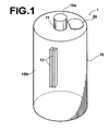
- Figure 1 is a perspective view showing an ink container used in the ink container loading structure of this embodiment.
- the ink container 1 used in the ink container loading structure comprises a substantially cylindrical ink container body 10 of resin and a storage means 20.
- a discharge port 11 through which ink filled in the ink container body 10 is discharged is provided in an upper end face 10a of the ink container body 10, and the storage means 20 is provided in a part of the upper end face 10a of the ink container body 10.
- the storage means 20 is a memory IC having a data communication portion.
- a pair of ribs 12 each in the form of a flat plate are provided in parallel to the central axis of the ink container body 10 on a side 10b thereof.
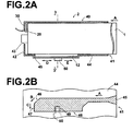
- Figure 2A is a cross-sectional view of an ink container loading portion used in the ink container loading structure loaded with an ink container 1.
- the ink container loading portion 2 used in the ink container loading structure is substantially of a cylinder which is larger in diameter than the ink container 1 and is formed of resin and comprises an ink container loading portion body 40 in which the ink container is loaded, a read-out means 30 which reads out predetermined information from the storage means 20 on the ink container 1 and a fixing portion 50 to be described later, as shown in Figure 2A .
- the ink container loading portion body 40 is in the form of a cylinder which has no circular end wall at one end thereof, and the end provided with no circular end wall forms an ink container insertion port 41. Into the ink container insertion port 41, the ink container 1 is inserted in the direction of arrow A.
- a circular wall 42 at the other end of the ink container loading portion body 40 is provided with a hole 43 through which the ink discharge port 11 of the inserted ink container 1 projects outside.
- An ink suction pump which sucks the ink from the ink container 1, and the like are connected to the ink discharge port 11 of the ink container 1 projected through the hole 43.
- a read-out means 30 is provided on the inner side of the circular wall 42 as shown in Figure 2A .
- a groove 45 by which the ribs 12 on the ink container body 10 is guided and fixed is formed on a part of the inside of a side portion 44 of the ink container loading portion body 40 as shown Figure 2B .
- the groove 45 comprises a longitudinal guide portion which guides the ribs 12 on the ink container 1 in the direction of arrow A when the ink container 1 is inserted into the ink container insertion port 41 in the direction of arrow A, an oblique guide portion which guides the ribs 12 on the ink container 1 in the direction of arrow B by causing the end of the ribs 12 to slide along a surface 46 after guided in the direction of arrow A, and a circumferential guide portion which, when the end of the ribs 12 abut against a surface 47 after the ribs 12 are guided by the oblique guide portion, guides the end of the ribs 12 along the surface 47 in the direction of arrow C so that the ribs 12 are brought into abutment against and fixed by a surface 48
- the part near the ink container insertion port 41 of the longitudinal guide portion is wider than a linear portion to facilitate insertion of the ribs 12 on the ink container 1. Further, the width of the circumferential guide portion in the direction of arrow A is formed to conform to the length of the ribs 12 so that when the ribs 12 abut against the surface 48, the position of the ribs 12 in the direction of arrow D (the direction in which the storage means 20 and the read-out means 30 are opposed to each other) is fixed.
- the ribs 12 on the ink container 1 and the groove 45 on the ink container loading portion 2 are positioned so that the space between the storage means 20 and the read-out means 30 does not become not smaller than a predetermined value when the ribs 12 on the ink container 1 abut against the surface 48 of the groove 45 and the position of the ribs 12 in the direction of arrow D is fixed as shown in Figure 2A . Further, the space is selected so that the read-out means 30 can suitably communicate with the storage means 20 to suitably read out the data from the storage means 20.
- the position of the ribs 12 in the direction of arrow D is fixed by the groove 45 in this embodiment, it is not necessary to fix the position of the ribs 12 in the direction of arrow D so long as the position of the ribs 12 is limited from being moved in the direction of the arrow E (toward the storage means 20 in the direction in which the storage means 20 and the read-out means 30 are opposed to each other.
- a hole 49 is formed in the ink container loading portion body 40.
- the hole 49 is formed so that the fixing portion 50 (to be described later) formed on the outer side of the side portion 44 of the ink container loading portion body 40 is brought into abutment against the ribs 12 when the ribs 12 is brought into abutment against the surface 48 of the groove 45.
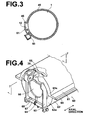
- Figure 3 is a cross-sectional view taken along line 3-3 in Figure 2A showing the ink container loading portion 2 and the ink container 1 shown in Figure 2A .
- the fixing portion 50 is formed on the outer side of the side portion 44 of the ink container loading portion body 40.
- the fixing portion 50 is provided with a spring switch 51 having a projection and when the ink container 1 is loaded in the ink container loading portion 2, the projection of the spring switch 51 is engaged with the space between the two ribs 12 of the ink container 1 to fix the position of the ribs 12 of the ink container 1 in the circumferential direction.
- the ribs 12 on the ink container 1, the hole 49 and the fixing portion 50 of the ink container loading portion 2 are located so that the storage means 20 and the read-out means 30 are opposed to each other.
- the ink container 1 provided with the ribs 12 in the manner described above is loaded in the ink container loading portion 2 provided with the groove 45, the hole 49 and the fixing portion 50 in the manner described above, the ink container 1 is inserted in the direction of arrow A with the ribs 12 on the ink container 1 guided in the direction of arrow A by the longitudinal direction guide portion of the groove 45.
- the ink container 1 is rotated in its circumferential direction and at the same time is further inserted in the direction of arrow A as the ribs 12 are guided in the direction of arrow B after the end of the ribs 12 guided in the direction of arrow A is brought into abutment against surface 46 of the oblique guide portion and the end of the ribs 12 slides along the surface 46, and is further rotated in its circumferential direction as the ribs 12 are guided in the direction of arrow C with the end thereof slid along the surface 47 after the end of the ribs 12 guided in the direction of arrow B abuts against the surface 47 of the circumferential guide portion.
- the space between the storage means 20 of the ink container 1 and the read-out means 30 of the ink container mounting portion 2 does not become not smaller than a predetermined value and at the same time the storage means 20 and the read-out means 30 can be positioned opposed to each other, whereby delivery and receipt of data between the storage means 20 and the read-out means 30 can be always suitably performed.
- the positions of the storage means 20 and the read-out means 30 in the direction in which they are opposed to each other are fixed by respectively providing the ink container 1 and the ink container loading portion 2 with the ribs 12 and the groove 45 and rotation of the ink container 1 in a circumferential direction is fixed by providing the ink container loading portion 2 with the fixing portion 50, only the positions of the storage means 20 and the read-out means 30 in the direction in which they are opposed to each other may be fixed, or only rotation of the ink container 1 in a circumferential direction may be fixed.
- the ribs 12 are provided on the ink container 1 and movement of the ribs 12 are controlled by the groove 45, it is not necessary to provide a protrusion such as ribs 12 on the ink container 1 but a surface of the ink container 1, for instance, the bottom surface thereof may be used.
- movement of the ink container 1 may be controlled by bringing the bottom surface into abutment against the ink container movement limiting portion.
- the positions of the storage means 20 and the read-out means 30 in the direction in which they are opposed to each other are fixed by respectively providing the ink container 1 and the ink container loading portion 2 with the ribs 12 and the groove 45
- the positions of the storage means 20 and the read-out means 30 in the direction in which they are opposed to each other are fixed may be fixed or the ink container 1 may be prevented from being moved toward the storage means 20 in the direction in which they are opposed to each other by other arrangements without limited to such arrangement.
- rotation of the ink container 1 in a circumferential direction may also be fixed by other arrangements.
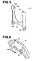
- the ink container loading structure of this embodiment has an ink container loading portion 60 which comprises, as shown in Figure 4 , an ink container loading portion body 69 formed by upper and lower semi-cylindrical members, that is, an upper ink container loading portion body 61 and a lower ink container loading portion body 62, a holding base 63 which is supported to be movable back and forth toward the storage means 20 of the ink container 1 loaded in the cylinder of the ink container loading portion body 69, an urging means 64 urging the holding base 63 toward the storage means 20 of the ink container 1 and a read-out means installment member 65 which is mounted for rotation on the holding base 63. Further, a support shaft 67 supporting the holding base 63 and a shaft fixing portion 68 for fixing the support shaft 67 to the lower ink container loading portion body 62 are provided on the lower ink container loading portion body 62.
- the ink container loading portion body 69 is provided with a groove 45, by which ribs 12 on the ink container body 10 is guided and fixed, on a part of the inside of a side portion as in the ink container loading portion 2 of the first embodiment and a fixing portion the same as the fixing portion 50 of the first embodiment.
- the holding base 63 is mounted on the lower ink container loading portion body 62 so that when the ink container 1 is fixed by the groove 45 and the fixing member, the storage 20 of the ink container 1 and the read-out means installment member 65 are opposed to each other.
- the upper and lower ink container loading portion bodies 61 and 62 are respectively provided in their end walls 61a and 62a with semi-circular cutaway portions for forming a hole 66 through which the ink discharge port 11 of the ink container 1 projects outside the ink container loading portion body 69. Further, in Figure 4 , a part of the upper ink container loading portion body 61 is abbreviated in order to clearly show the positional relation between the ink container loading portion body 69 and the read-out means installment member 65. Though, in this particular embodiment, the groove and the fixing portion are provided on the ink container loading portion body 69, it is not essential.
- FIG. 5 is a perspective view in an enlarged scale of the holding base 63 shown in Figure 4 .
- the holding base 63 is U-shaped and comprises a support portion 63a on which the read-out means installment member 65 is mounted for rotation, a bearing portion 63b on which the support shaft 67 supporting the holding base 63 to be movable back and forth toward the storage means 20 of the ink container 1, a spring groove 63c against which a part of the urging means 64 abuts and a hook portion 63d which suppress the holding base 63 from being moved toward the storage means 20.
- Figure 6 is a perspective view in an enlarged scale of the read-out means installment member 65 shown in Figure 4 .
- the read-out means installment member 65 is articulate to conform to the shape of the upper ink container loading portion body 61 and the ink container 1 and comprises a hole 65a with which the support portion 63a of the holding base 63 is engaged for rotation, a mounting surface 65b on which the read-out means 30 is mounted, and an engagement portion 65c which engages with the read-out means 30 on the mounting surface 65b.
- the urging means 64 shown in Figure 4 is in the form of a spring which are received in the spring groove 63c of the holding base 63 at one end and engaged with the lower ink container loading portion body 62 at the other end, thereby urging the holding base 63 toward the storage means 20 of the ink container 1.
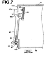
- Figure 7 is a cross-sectional view taken along line 7-7 of the ink container loading portion 60 shown in Figure 4 .
- the ink container loading portion 60 shown in Figure 7 is in a state before loading an ink container.
- the upper and lower ink container loading portion bodies 61 and 62 are combined with each other with their end walls 61a and 62a shifted in the axial direction of the ink container loading portion body 69 and at the same time, with the end wall 61a of the upper ink container loading portion body 61 positioned between the hook portion 63d of the holding base 63 and the read-out means installment member 65.
- the holding base 63 is mounted on the support shaft 67 to be movable back and forth about the support shaft 67 between a position where the hook portion 63d of the holding base 63 abuts against the end wall 61a and a position where the read-out means installment member 65 abuts against the back surface of the end wall 61a.
- the holding base 63 is urged in the direction of arrow X1, that is, toward the storage means 20 by the urging means 64 so that its hook portion 63d is supported in abutment against the end wall 61a of the upper ink container loading portion body 61 and the read-out means installment member 65 is rotatable in the direction of arrow Y.
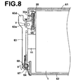
- Figure 8 is a view showing a state where the ink container loading portion 60 shown in Figure 7 is loaded with an ink container 1.
- the storage means 20 of the ink container 1 abuts against the read-out means installment member 65
- the read-out means installment member 65 is moved in synchronization with movement of the ink container 1 in the direction of insertion, and the holding base 63 supported for rotation in the directions of arrows X1 and X2 is moved in the direction of arrow X2 together with the read-out means installment member 65 as shown in Figure 8 .
- the read-out means installment member 65 mounted for rotation in the direction of arrow Y on the holding base 63 is rotated about the support portion 63a along the storage means 20.
- the read-out means installment member 65 and the storage means 20 are positioned in parallel to each other, and the space between the read-out means 30 installed in the read-out means installment member 65 and the storage means 20 can be held constant.
- a cutaway portion which permits a projection 30a on the read-out means 30 to pass through is formed in a part of the end wall 61a.
- the storage means 20 and the read-out means installment member 65 are in direct contact with each other, by providing a recess 3 in the ink container 2, placing the storage means 20 on a bottom surface 3a of the recess 3 and bringing the read-out means installment member 65 and a periphery of the recess 3 in contact with each other as shown in Figure 9 , the read-out means 30 may be positioned along the storage means 20 to hold constant the space between the read-out means 30 and the storage means 20. Further, it is possible to hold constant the space between the storage means 20 and the read-out means 30 by providing a protrusion around the storage means 20 of the ink container 2 and causing the read-out means installment member 65 to be in contact with the protrusion.
- the arrangement of the holding base 63 and the like in the second embodiment need not be limited to the illustrated arrangement but may be of other arrangements.
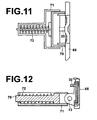
- the holding base 70 may be mounted as shown in Figure 10 , a fixing member 71 which supports the holding base 70 to be movable back and forth toward the storage means 20 of the ink container 1 may be provided in the upper ink container loading body portion 61, and the holding base 70 may be urged toward the storage means 20 on the ink container 1 (toward the direction of arrow Z1) by an urging means 72 such as a spring provided in the fixing member 71.
- a plan view of the holding base 70 and the fixing member 71, and the like shown in Figure 10 is shown in Figure 11
- a cross-sectional view taken along line 12-12 in Figure 10 is shown in Figure 12 .
- the storage means 20 on the ink container 1 is brought into abutment against the read-out means installment member 65 when the ink container 1 is loaded, the read-out means installment member 65 is moved in response to movement of the ink container 1 in the direction of loading, and the holding base 70 is moved in the direction of arrow Z2 in response to movement of the read-out means installment member 65 together with the read-out means installment member 65. Since the holding base 70 is urged in the direction arrow Z1 by the urging means 72, the read-out means installment member 65 mounted for rotation on the holding base 63 is rotated about the support portion 70 along the storage means 20. As a result, the read-out means installment member 65 and the storage means 20 are positioned in parallel to each other, and the space between the read-out means 30 installed in the read-out means installment member 65 and the storage means 20 can be held constant.
- the shape and the arrangement of the holding base, urging means, read-out means installment member and the like in the second embodiment need not be limited to the illustrated shape and arrangement but may be of other shapes and arrangements, without departing from the scope of the invention, which is defined by the appended claims.
Landscapes
- Ink Jet (AREA)
- Inking, Control Or Cleaning Of Printing Machines (AREA)
Claims (3)
- Tintenbehälter-Ladevorrichtung, umfassend einen Tintenbehälter (1), der mit einer Speichereinrichtung (20) ausgestattet ist, in welcher vorbestimmte Information gespeichert ist, und einen Tintenbehälter-Ladeteil (2), in welchem der Tintenbehälter (1) aufgenommen ist, und der mit einer Leseeinrichtung (30) zum Auslesen der in der Speichereinrichtung (20) gespeicherten Information versehen ist, dadurch gekennzeichnet, dass
der Tintenbehälter-Ladeteil (2) ausgestattet ist mit
einer Haltebasis (63), die gelagert ist, um in Richtung der Speichereinrichtung (2) des Tintenbehälters (1) vorgerückt und abgerückt zu werden,
einer Belastungseinrichtung (64), welche die Haltebasis (63) in Richtung der Speichereinrichtung (20) des Tintenbehälters (1) drängt, und
einem Leseeinrichtungs-Installationselement (65), welches gelagert ist für eine Drehung auf der Haltebasis (63), und in dem die Leseeinrichtung (30) installiert ist. - Tintenbehälter-Ladevorrichtung nach Anspruch 1, weiterhin umfassend einen Tintenbehälterbewegungs-Begrenzungsteil (45), der eine Bewegung des Tintenbehälters (1) in Richtung der Speichereinrichtung (20) in der Richtung begrenzt, in der die Speichereinrichtung (20) und die Leseeinrichtung (30) einander gegenüberliegen, so dass der Abstand zwischen der Leseeinrichtung (30) und der Speichereinrichtung (20) nicht kleiner als ein vorbestimmter Wert wird.
- Tintenbehälter-Ladevorrichtung nach Anspruch 1, in der der Tintenbehälter (1) zylindrisch und mit einem Vorsprung oder einer Ausnehmung (12) ausgestattet ist, und
der Tintenbehälter-Ladeteil (2) mit einem Fixierteil (50) versehen ist, der die Speichereinrichtung (20) und die Leseeinrichtung (30) dazu bringt, einander gegenüber positioniert zu werden, indem die Lage des Vorsprungs oder der Ausnehmung (12) in Umfangsrichtung des Tintenbehälters fixiert wird.
Applications Claiming Priority (5)
| Application Number | Priority Date | Filing Date | Title |
|---|---|---|---|
| JP2003045567 | 2003-02-24 | ||
| JP2003045567 | 2003-02-24 | ||
| JP2003351826 | 2003-10-10 | ||
| JP2003351826A JP2004276589A (ja) | 2003-02-24 | 2003-10-10 | インク容器およびインク容器装填構造 |
| PCT/JP2003/016317 WO2004073993A1 (ja) | 2003-02-24 | 2003-12-19 | インク容器およびインク容器装填構造 |
Publications (3)
| Publication Number | Publication Date |
|---|---|
| EP1598204A1 EP1598204A1 (de) | 2005-11-23 |
| EP1598204A4 EP1598204A4 (de) | 2007-01-03 |
| EP1598204B1 true EP1598204B1 (de) | 2011-03-23 |
Family
ID=32911434
Family Applications (1)
| Application Number | Title | Priority Date | Filing Date |
|---|---|---|---|
| EP03780924A Expired - Lifetime EP1598204B1 (de) | 2003-02-24 | 2003-12-19 | Montagestruktur für tintenbehälter |
Country Status (5)
| Country | Link |
|---|---|
| US (1) | US7407266B2 (de) |
| EP (1) | EP1598204B1 (de) |
| JP (1) | JP2004276589A (de) |
| DE (1) | DE60336508D1 (de) |
| WO (1) | WO2004073993A1 (de) |
Families Citing this family (2)
| Publication number | Priority date | Publication date | Assignee | Title |
|---|---|---|---|---|
| JP2007090736A (ja) * | 2005-09-29 | 2007-04-12 | Brother Ind Ltd | インクカートリッジ |
| CN107020826B (zh) * | 2016-01-29 | 2019-01-15 | 理想科学工业株式会社 | 墨盒、该盒上的标签剥离方法以及墨盒的再生产方法 |
Family Cites Families (21)
| Publication number | Priority date | Publication date | Assignee | Title |
|---|---|---|---|---|
| US4937775A (en) | 1988-11-21 | 1990-06-26 | General Electric Company | Apparatus for the cross-correlation of a pair of complex sampled signals |
| JP2571259Y2 (ja) * | 1989-02-23 | 1998-05-18 | 理想科学工業 株式会社 | インク容器 |
| US6130695A (en) | 1995-04-27 | 2000-10-10 | Hewlett-Packard Company | Ink delivery system adapter |
| US6074042A (en) | 1997-06-04 | 2000-06-13 | Hewlett-Packard Company | Ink container having a guide feature for insuring reliable fluid, air and electrical connections to a printing system |
| US6290343B1 (en) | 1996-07-15 | 2001-09-18 | Hewlett-Packard Company | Monitoring and controlling ink pressurization in a modular ink delivery system for an inkjet printer |
| JPH10133529A (ja) | 1996-11-05 | 1998-05-22 | Omron Corp | 交換部品使用状態記録装置及び液体容器 |
| US7188918B2 (en) | 1997-01-21 | 2007-03-13 | Hewlett-Packard Development Company, L.P. | Ink delivery system adapter |
| US6322205B1 (en) | 1997-01-21 | 2001-11-27 | Hewlett-Packard Company | Ink delivery system adapter |
| EP1275512A1 (de) * | 1997-06-04 | 2003-01-15 | Hewlett-Packard Company | Tintenzuführsystemadapter |
| JP2000015916A (ja) | 1998-07-03 | 2000-01-18 | Riso Kagaku Corp | 組み合わせ検出装置 |
| JP3250556B2 (ja) * | 1998-11-11 | 2002-01-28 | セイコーエプソン株式会社 | インクジェット式印刷装置、インクカートリッジのメモリ装置へのアクセス方法、及び印刷装置の制御方法 |
| US6385407B1 (en) * | 1998-12-28 | 2002-05-07 | Hitachi Maxell, Ltd. | Accommodating enclosure and management system |
| JP3755755B2 (ja) * | 1999-07-14 | 2006-03-15 | セイコーエプソン株式会社 | インクカートリッジおよびこれを用いたインクジェット式記録装置並びに同装置へのインクカートリッジの装着可否判定方法。 |
| US6697578B2 (en) | 2000-08-25 | 2004-02-24 | Canon Kabushiki Kaisha | Memory member, unit, process cartridge and electrophotographic image forming apparatus |
| JP3461331B2 (ja) | 2000-08-25 | 2003-10-27 | キヤノン株式会社 | メモリー部材、ユニット、プロセスカートリッジ、及び、電子写真画像形成装置 |
| JP2002172843A (ja) * | 2000-09-27 | 2002-06-18 | Riso Kagaku Corp | インクボトル装着装置及び該装置に用いるインクボトル |
| JP2002254673A (ja) | 2000-12-25 | 2002-09-11 | Seiko Epson Corp | インクジェット記録装置用インクカートリッジ |
| US6402309B1 (en) * | 2001-03-05 | 2002-06-11 | Inkjet, Inc. | Magnetically activated valve for ink |
| JP3815308B2 (ja) * | 2001-11-26 | 2006-08-30 | セイコーエプソン株式会社 | インクジェット記録装置およびインクカートリッジ |
| JP2003300358A (ja) * | 2002-04-10 | 2003-10-21 | Canon Inc | カートリッジ装着装置およびプリンタ装置 |
| DE60308460T2 (de) * | 2002-09-20 | 2007-10-31 | Océ-Technologies B.V. | Tintenbehälter und Befestigungssockel |
-
2003
- 2003-10-10 JP JP2003351826A patent/JP2004276589A/ja active Pending
- 2003-12-19 US US10/546,549 patent/US7407266B2/en not_active Expired - Lifetime
- 2003-12-19 DE DE60336508T patent/DE60336508D1/de not_active Expired - Lifetime
- 2003-12-19 WO PCT/JP2003/016317 patent/WO2004073993A1/ja not_active Ceased
- 2003-12-19 EP EP03780924A patent/EP1598204B1/de not_active Expired - Lifetime
Also Published As
| Publication number | Publication date |
|---|---|
| DE60336508D1 (de) | 2011-05-05 |
| JP2004276589A (ja) | 2004-10-07 |
| EP1598204A1 (de) | 2005-11-23 |
| US20060152538A1 (en) | 2006-07-13 |
| EP1598204A4 (de) | 2007-01-03 |
| WO2004073993A1 (ja) | 2004-09-02 |
| US7407266B2 (en) | 2008-08-05 |
Similar Documents
| Publication | Publication Date | Title |
|---|---|---|
| US7490929B2 (en) | Ink cartridge and ink cartridge holder | |
| EP1352748B1 (de) | Funkverbindung zwischen Aufzeichnungs-Flüssigkeitsbehälter und Tintenstrahl-Aufzeichnungsvorrichtung | |
| US20090123207A1 (en) | Spool adapter | |
| EP1598204B1 (de) | Montagestruktur für tintenbehälter | |
| KR20200136968A (ko) | 인쇄 카트리지, 테이프 가이드 및 인쇄 장치 | |
| CN101151162A (zh) | 液体盒、液体盒装载/卸载设备、记录装置和液体喷射装置 | |
| KR100545412B1 (ko) | 열전사인자기의 잉크리본권장용 코어, 잉크리본카세트 | |
| US6244677B1 (en) | Array and method for standardizing cartridge location within storage cells of a data storage library | |
| EP2159795B1 (de) | Aufzeichnungsbandkassette | |
| EP3446883B1 (de) | Bandkassette | |
| KR100246826B1 (ko) | 열전사 프린터 | |
| CA2280678A1 (en) | Sim card reader connector | |
| JP2004255586A (ja) | インク容器装填構造およびインク容器装填部並びにインク容器 | |
| CN108569052A (zh) | 带打印装置 | |
| JP4778367B2 (ja) | チューブラック | |
| JP2003200630A (ja) | 画像形成装置 | |
| CN111976321A (zh) | 带标签的产品和盖子 | |
| CN115195299A (zh) | 印刷装置 | |
| HK1058337B (en) | Ink cartridge and ink cartridge holder | |
| JP2020147320A (ja) | インクリボン収納容器 | |
| HK1116143A (en) | Ink cartridge |
Legal Events
| Date | Code | Title | Description |
|---|---|---|---|
| PUAI | Public reference made under article 153(3) epc to a published international application that has entered the european phase |
Free format text: ORIGINAL CODE: 0009012 |
|
| 17P | Request for examination filed |
Effective date: 20050824 |
|
| AK | Designated contracting states |
Kind code of ref document: A1 Designated state(s): AT BE BG CH CY CZ DE DK EE ES FI FR GB GR HU IE IT LI LU MC NL PT RO SE SI SK TR |
|
| RBV | Designated contracting states (corrected) |
Designated state(s): DE FR GB |
|
| A4 | Supplementary search report drawn up and despatched |
Effective date: 20061204 |
|
| 17Q | First examination report despatched |
Effective date: 20100401 |
|
| GRAP | Despatch of communication of intention to grant a patent |
Free format text: ORIGINAL CODE: EPIDOSNIGR1 |
|
| RTI1 | Title (correction) |
Free format text: INK CONTAINER LOADING STRUCTURE |
|
| GRAS | Grant fee paid |
Free format text: ORIGINAL CODE: EPIDOSNIGR3 |
|
| GRAA | (expected) grant |
Free format text: ORIGINAL CODE: 0009210 |
|
| AK | Designated contracting states |
Kind code of ref document: B1 Designated state(s): DE FR GB |
|
| REG | Reference to a national code |
Ref country code: GB Ref legal event code: FG4D |
|
| REF | Corresponds to: |
Ref document number: 60336508 Country of ref document: DE Date of ref document: 20110505 Kind code of ref document: P |
|
| REG | Reference to a national code |
Ref country code: DE Ref legal event code: R096 Ref document number: 60336508 Country of ref document: DE Effective date: 20110505 |
|
| PLBE | No opposition filed within time limit |
Free format text: ORIGINAL CODE: 0009261 |
|
| STAA | Information on the status of an ep patent application or granted ep patent |
Free format text: STATUS: NO OPPOSITION FILED WITHIN TIME LIMIT |
|
| 26N | No opposition filed |
Effective date: 20111227 |
|
| REG | Reference to a national code |
Ref country code: DE Ref legal event code: R097 Ref document number: 60336508 Country of ref document: DE Effective date: 20111227 |
|
| REG | Reference to a national code |
Ref country code: FR Ref legal event code: PLFP Year of fee payment: 13 |
|
| REG | Reference to a national code |
Ref country code: FR Ref legal event code: PLFP Year of fee payment: 14 |
|
| REG | Reference to a national code |
Ref country code: DE Ref legal event code: R082 Ref document number: 60336508 Country of ref document: DE Representative=s name: KLUNKER IP PATENTANWAELTE PARTG MBB, DE |
|
| REG | Reference to a national code |
Ref country code: FR Ref legal event code: PLFP Year of fee payment: 15 |
|
| PGFP | Annual fee paid to national office [announced via postgrant information from national office to epo] |
Ref country code: GB Payment date: 20221223 Year of fee payment: 20 Ref country code: FR Payment date: 20221222 Year of fee payment: 20 Ref country code: DE Payment date: 20220621 Year of fee payment: 20 |
|
| P01 | Opt-out of the competence of the unified patent court (upc) registered |
Effective date: 20230323 |
|
| REG | Reference to a national code |
Ref country code: DE Ref legal event code: R071 Ref document number: 60336508 Country of ref document: DE |
|
| REG | Reference to a national code |
Ref country code: GB Ref legal event code: PE20 Expiry date: 20231218 |
|
| PG25 | Lapsed in a contracting state [announced via postgrant information from national office to epo] |
Ref country code: GB Free format text: LAPSE BECAUSE OF EXPIRATION OF PROTECTION Effective date: 20231218 |
|
| PG25 | Lapsed in a contracting state [announced via postgrant information from national office to epo] |
Ref country code: GB Free format text: LAPSE BECAUSE OF EXPIRATION OF PROTECTION Effective date: 20231218 |