EP1598128A1 - Verfahren zur herstellung eines metallrings für endlosmetallband - Google Patents
Verfahren zur herstellung eines metallrings für endlosmetallband Download PDFInfo
- Publication number
- EP1598128A1 EP1598128A1 EP04713235A EP04713235A EP1598128A1 EP 1598128 A1 EP1598128 A1 EP 1598128A1 EP 04713235 A EP04713235 A EP 04713235A EP 04713235 A EP04713235 A EP 04713235A EP 1598128 A1 EP1598128 A1 EP 1598128A1
- Authority
- EP
- European Patent Office
- Prior art keywords
- metal ring
- unevenness
- rolling roller
- grinder
- mesh
- Prior art date
- Legal status (The legal status is an assumption and is not a legal conclusion. Google has not performed a legal analysis and makes no representation as to the accuracy of the status listed.)
- Withdrawn
Links
Images
Classifications
-
- B—PERFORMING OPERATIONS; TRANSPORTING
- B23—MACHINE TOOLS; METAL-WORKING NOT OTHERWISE PROVIDED FOR
- B23P—METAL-WORKING NOT OTHERWISE PROVIDED FOR; COMBINED OPERATIONS; UNIVERSAL MACHINE TOOLS
- B23P9/00—Treating or finishing surfaces mechanically, with or without calibrating, primarily to resist wear or impact, e.g. smoothing or roughening turbine blades or bearings; Features of such surfaces not otherwise provided for, their treatment being unspecified
- B23P9/02—Treating or finishing by applying pressure, e.g. knurling
-
- B—PERFORMING OPERATIONS; TRANSPORTING
- B21—MECHANICAL METAL-WORKING WITHOUT ESSENTIALLY REMOVING MATERIAL; PUNCHING METAL
- B21B—ROLLING OF METAL
- B21B5/00—Extending closed shapes of metal bands by rolling
-
- B—PERFORMING OPERATIONS; TRANSPORTING
- B21—MECHANICAL METAL-WORKING WITHOUT ESSENTIALLY REMOVING MATERIAL; PUNCHING METAL
- B21H—MAKING PARTICULAR METAL OBJECTS BY ROLLING, e.g. SCREWS, WHEELS, RINGS, BARRELS, BALLS
- B21H1/00—Making articles shaped as bodies of revolution
- B21H1/06—Making articles shaped as bodies of revolution rings of restricted axial length
-
- B—PERFORMING OPERATIONS; TRANSPORTING
- B24—GRINDING; POLISHING
- B24B—MACHINES, DEVICES, OR PROCESSES FOR GRINDING OR POLISHING; DRESSING OR CONDITIONING OF ABRADING SURFACES; FEEDING OF GRINDING, POLISHING, OR LAPPING AGENTS
- B24B19/00—Single-purpose machines or devices for particular grinding operations not covered by any other main group
- B24B19/02—Single-purpose machines or devices for particular grinding operations not covered by any other main group for grinding grooves, e.g. on shafts, in casings, in tubes, homokinetic joint elements
-
- F—MECHANICAL ENGINEERING; LIGHTING; HEATING; WEAPONS; BLASTING
- F16—ENGINEERING ELEMENTS AND UNITS; GENERAL MEASURES FOR PRODUCING AND MAINTAINING EFFECTIVE FUNCTIONING OF MACHINES OR INSTALLATIONS; THERMAL INSULATION IN GENERAL
- F16G—BELTS, CABLES, OR ROPES, PREDOMINANTLY USED FOR DRIVING PURPOSES; CHAINS; FITTINGS PREDOMINANTLY USED THEREFOR
- F16G5/00—V-belts, i.e. belts of tapered cross-section
- F16G5/16—V-belts, i.e. belts of tapered cross-section consisting of several parts
-
- B—PERFORMING OPERATIONS; TRANSPORTING
- B21—MECHANICAL METAL-WORKING WITHOUT ESSENTIALLY REMOVING MATERIAL; PUNCHING METAL
- B21B—ROLLING OF METAL
- B21B1/00—Metal-rolling methods or mills for making semi-finished products of solid or profiled cross-section; Sequence of operations in milling trains; Layout of rolling-mill plant, e.g. grouping of stands; Succession of passes or of sectional pass alternations
- B21B1/22—Metal-rolling methods or mills for making semi-finished products of solid or profiled cross-section; Sequence of operations in milling trains; Layout of rolling-mill plant, e.g. grouping of stands; Succession of passes or of sectional pass alternations for rolling plates, strips, bands or sheets of indefinite length
- B21B1/227—Surface roughening or texturing
-
- B—PERFORMING OPERATIONS; TRANSPORTING
- B21—MECHANICAL METAL-WORKING WITHOUT ESSENTIALLY REMOVING MATERIAL; PUNCHING METAL
- B21B—ROLLING OF METAL
- B21B27/00—Rolls, roll alloys or roll fabrication; Lubricating, cooling or heating rolls while in use
- B21B27/005—Rolls with a roughened or textured surface; Methods for making same
-
- B—PERFORMING OPERATIONS; TRANSPORTING
- B21—MECHANICAL METAL-WORKING WITHOUT ESSENTIALLY REMOVING MATERIAL; PUNCHING METAL
- B21H—MAKING PARTICULAR METAL OBJECTS BY ROLLING, e.g. SCREWS, WHEELS, RINGS, BARRELS, BALLS
- B21H8/00—Rolling metal of indefinite length in repetitive shapes specially designed for the manufacture of particular objects, e.g. checkered sheets
- B21H8/005—Embossing sheets or rolls
Definitions
- the present invention relates to a method for manufacturing a thin-sheet metal ring for use in an endless metal belt.
- Belts for transmitting power in a continuously variable transmission are formed by bonding together a plurality of elements that are arranged and stacked annularly using laminated rings.
- the laminated rings are formed by laminating a plurality of metal rings.
- the metal rings used to form this type of laminated rings receive load in the laminated state, by which friction is caused to occur between the metal rings. Therefore, lack of lubrication between the metal rings may cause drawbacks such as generation of heat or seizing of adjacent metal rings due to friction.
- S55-103133 discloses a prior art metal ring having a mesh-like unevenness formed to the inner circumferential surface of the ring, and creating a lubricant film using this mesh-like unevenness (refer to page 2 and FIG. 1 of the publication).
- a known method for forming a mesh-like unevenness on the inner circumferential surface of a metal ring comprises forming grooves on the surface of a rolling roller for rolling the metal ring, and rolling the metal ring using this rolling roller to thereby transfer the groove unevenness to the surface of the metal ring to form projections thereto.
- Japanese Patent Laid-Open Publication No. S61-79041 discloses forming grooves one at a time on the surface of the rolling roller using a single-grain diamond. Actually, the single-grain diamond is pressed onto the surface of a rotating rolling roller, and the diamond is moved back and forth within the predetermined width of the rolling roller in the axial direction, in order to form the mesh-like projection on the surface (refer to page 4 and FIG. 9 of the publication).
- the grooves formed in the manner disclosed in Japanese Patent Laid-Open Publication No. S61-79041 are processed using a single-grain diamond or the like, so unless the width between the grooves is widened to a certain level, the processing of the rolling roller takes too much time.
- the projections formed to the surface of the metal ring by transferring the groove unevenness tend to receive concentrated stress.
- the compressive residual stress occurring on the surface of the metal ring may be concentrated on the projection, causing deterioration of durability.
- the grooves are formed one at a time using a single-grain diamond, so the processing of the rolling roller takes time. Moreover, when the grooves on the surface of the rolling roller are worn during use and can no longer transfer the predetermined unevenness to the metal ring, the surface of the rolling roller must first be polished to eliminate the grooves before creating new grooves thereto. Thus, according to the prior art, the processing and maintenance of the rolling roller required much man-hour.
- the present invention aims at improving the method for manufacturing a thin-sheet metal ring for use in an endless metal belt. In further detail, the present invention aims at solving the problems mentioned above by manufacturing a metal ring with reduced stress concentration. Another object of the present invention is to provide a method for manufacturing a metal ring that utilizes a rolling roller for rolling the metal ring that is easy to manufacture and maintain.
- the present invention provides a method for manufacturing a thin-sheet metal ring for use in an endless metal belt, comprising a rolling step for rolling the metal ring using a rolling roller, wherein a mesh-like unevenness is formed on at least a surface of the rolling roller coming into contact with an inner circumferential surface of the metal ring, the mesh-like unevenness on the rolling roller is formed by applying a grinder having a predetermined coarseness on a rotating rolling roller and moving the grinder in an axial direction of the roller, and the mesh-like unevenness formed on the rolling roller is transferred to the metal ring during the rolling step.
- the mesh-like unevenness on the metal ring is formed by transferring the mesh-like unevenness formed to the rolling roller using a grinder with a predetermined coarseness. Therefore, the present invention enables to form an unevenness having a narrower size and width compared to the projections formed by transferring the grooves created using diamond according to the prior art. Thus, stress concentration on the mesh-like unevenness can be suppressed.
- the mesh-like unevenness on the rolling roller there is no need to form the mesh-like unevenness on the rolling roller one groove at a time using a single-grain diamond or the like. Therefore, the mesh-like unevenness can be formed easily on the surface of the rolling roller. When the unevenness on the rolling roller is worn by use, a new mesh-like unevenness can be formed over the worn unevenness using the above-mentioned grinder. Unlike the prior art method, there is no need according to the present invention to polish the surface of the roller before forming a new groove thereto, so the maintenance of the rolling roller is facilitated.
- the width of the grooves of the mesh-like unevenness on the rolling roller is formed randomly between 25 ⁇ m and 250 ⁇ m, stress concentration on the meshed unevenness can be suppressed.
- the term random means that the width of the groove is not fixed but varied.
- the rolling roller of the present invention can have a mesh-like unevenness newly formed thereto by processing a surface of the mesh-like unevenness that has been worn through use with the grinder. Since the mesh-like unevenness is formed using a grinder, there is no need to polish the surface of the rolling roller as in the prior art method, so the mesh-like unevenness can be formed easily.
- the metal ring is made of maraging steel
- the grinder for processing the rolling roller has a coarseness in the grain size range between #270 and #1000, and a nitriding treatment for nitriding the metal ring is performed after the rolling step.
- the surface of the metal ring on which the mesh-like unevenness is transferred has an increased surface area due to the unevenness, so nitriding can be performed smoothly. Further, the nitriding process creates compressive residual stress on the surface of the metal ring.
- the present inventors discovered through experiment that in order for the metal ring to have good durability, it is preferable that the maraging steel has a compressive residual stress of approximately -980 N/mm 2 or more. By using a grinder with a coarseness in the grain size range between #270 and #1000, the compressive residual stress of the metal ring can be set to approximately -980 N/mm 2 or more.
- the grinder for processing the rolling roller has a coarseness in the grain size range between #300 and #800.
- a solution treatment for solution treating the metal ring is performed to the metal ring after the rolling step and prior to the nitriding treatment.
- the crystal grain size of the metal ring becomes very fine. If the metal ring is subjected to nitriding treatment in this state, the fine grains are hardened uniformly, by which stress concentration is suppressed and fracture of the metal ring is avoided.
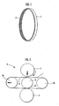
- FIG. 1 is an explanatory view showing a metal ring formed by the manufacturing method according to an embodiment of the present invention
- FIG. 2 is an explanatory view showing the main portion of a rolling apparatus for rolling the metal ring
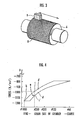
- FIG. 3 is an explanatory view showing an inner circumference rolling roller for rolling the inner circumferential surface of the metal ring
- FIG. 4 is a graph showing the relationship between the residual compressive stress on the inner circumferential surface of the metal ring and the grain size of a grinder.
- the metal ring 1 as shown in FIG. 1, is formed in the shape of a thin-sheet endless belt, for use in an endless metal belt of a belt-type continuously variable transmission.
- a mesh-like unevenness 2 is formed on the inner circumferential surface thereof, but no such processing is provided to the outer circumferential surface thereof, which is smooth.
- the rolling apparatus 3 has a pair of tension rollers 4a and 4b which are placed horizontally apart from each other by a predetermined distance for supporting a thin-sheet metal ring 1 thereon.
- the rolling apparatus also has a receive roller 5, an inner circumference rolling roller 6 and an outer circumference rolling roller 7, which are arrayed perpendicularly at the intermediate position between the tension rollers 4a and 4b.
- the outer circumference rolling roller 7 is disposed above the inner circumference rolling roller 6, and can be moved up and down.
- the outer circumference rolling roller 7 grips the metal ring 1 between itself and the inner circumference rolling roller 6 supported by the receive roller 5. Further, the outer circumference rolling roller 7 is driven to rotate by a motor not shown disposed on the back side thereof, thereby rolling the metal ring 1.
- the inner circumference rolling roller 6 and the method for processing the same will be described with reference to FIG. 3.
- the inner circumference rolling roller 6 according to the present embodiment has a mesh-like unevenness 8 formed on the surface thereof.
- the method for forming the mesh-like unevenness 8 is as follows. First, the inner circumference rolling roller 6 is rotated at a predetermined speed. Next, a grinder 9 is pressed with predetermined force to the surface of the inner circumference rolling roller 6 and moved back and forth in the axial direction of the inner circumference rolling roller 6. By applying the grinder 9 on the surface of a rotating inner circumference rolling roller 6 and moving the same back and forth in the axial direction, the mesh-shaped unevenness 8 is formed on the surface of the inner circumference rolling roller 6.
- the grinder 9 of the present embodiment utilizes a grinder made of diamond, and the grain size of the grinder is #325.
- the present inventors discovered through experiment that if a grinder with a grain size coarser than #270 is used, the mesh-like unevenness 8 formed to the surface of the inner circumference rolling roller 6 becomes too coarse, which is not preferable since it causes stress concentration on the unevenness 2 when transferred to the surface of the metal ring 1. Further, if a grinder with a grain size finer than #1000 is used, the depth of the unevenness 2 transferred to the surface of the metal ring 1 becomes insufficient, by which the ability to retain the lubricant during use as laminated ring is deteriorated.
- the pitch of the grinder 9 becomes finer, the life of the grinder itself becomes shorter and the grinder must be replaced frequently, so the productivity is degraded.
- the present inventors also discovered through experiment that in consideration of the condition of the unevenness 2 transferred onto the metal ring 1 and the life of the grinder, it is preferable to use a grinder with a grain size ranging between #300 and #800.
- the metal ring 1 is subjected to a rolling process in the rolling apparatus 3 illustrated in FIG. 2.
- the metal ring 1 is disposed around the left and right tension rollers 4a and 4b, and the ring 1 is gripped between the outer circumference rolling roller 7 and the inner circumference rolling roller 6 while it is rolled.
- the tension roller 4a is biased toward the left direction of FIG. 2 so as to provide a predetermined tension to the metal ring 1.
- the outer circumference rolling roller 7 is pressed with predetermined force toward the inner circumference rolling roller 6 while being rotated in the clockwise direction of FIG. 2.
- the metal ring 1 is rolled between the outer circumference rolling roller 7 and the inner circumference rolling roller 6, and at the same time, the metal ring 1 is rotated in the counterclockwise direction of FIG. 2 by the driving force of the outer circumference rolling roller 7. At this time, the inner circumferential surface of the metal ring 1 is pressed onto the mesh-like unevenness 8 formed to the surface of the inner circumference rolling roller 6, and the unevenness is impressed and transferred to the inner circumferential surface of the metal ring 1 as mesh-like unevenness 2.
- the solution treatment is performed by placing the metal ring 1 in a heating furnace (not shown) and heating the same to a temperature equal to or above the recrystallization temperature of maraging steel and equal to or below 850 oC.
- the metal ring 1 is subjected to nitriding treatment.
- the nitriding treatment is performed in a nitriding chamber (not shown) into which a mixed gas containing ammonia and nitrogen gas or a mixed gas containing ammonia and RX gas is introduced.
- the nitriding treatment is performed by heating the metal ring 1 to approximately 450 oC to 500 oC and maintaining the same for approximately 30 min to 120 min.
- the metal ring 1 formed by the above processes had a mesh-like unevenness 2 transferred to the inner circumferential surface thereof having a random width between 25 ⁇ m and 250 ⁇ m.
- the compressive residual stress of the metal ring 1 was approximately -1050 N/mm 2 (refer to point a of FIG. 4).
- the interval between the projections formed to the metal ring according to the prior art method was approximately 300 ⁇ m and was uniform, and the compressive residual stress on the inner circumferential surface of such prior art metal ring was approximately -800 N/mm 2 .
- the metal ring 1 formed by the method according to the present embodiment had a mesh-like unevenness 2 with a width finer than the prior art, and the compressive residual stress was increased.
- the compressive residual stress with respect to the grinder 9 is somewhat dispersed even if a grinder 9 of the same grain size is used, as shown by point c and point c' of FIG. 4, for example. This is considered to be caused by the dispersion in the processing speed or processing time when the rolling roller 6 is processed by the grinder 9.
- the compressive residual stress reaches -980 N/mm 2 or greater even by using a grinder with a grain size coarser than #250.
- the compressive residual stress may become smaller than -980 N/mm 2 as shown by point d' of FIG. 4 due to dispersion of processes, so according to the present embodiment, the coarseness of the grinder 9 should be finer than approximately #270.
- the solution treatment is performed after the rolling process, so the crystal grain size of the unevenness 2 formed to the metal ring 1 becomes finer, and the toughness of the formed metal ring 1 is enhanced.
- the metal rings 1 thus manufactured according to the present embodiment are applied as laminated ring to the metal belt of a continuously variable transmission, good lubrication between the plural metal rings 1 is achieved by the unevenness 2. Further, since the ring has high compressive residual stress and enhanced toughness, it is stronger against metal fatigue.
- the inner circumferential rolling roller 6 is processed using a grinder 9, the process time is shortened compared to the case in which a single diamond is used for the process. Moreover, upon performing maintenance of the inner circumference rolling roller 6, the surface can be directly processed by the grinder 9 without having to polish off the unevenness 8 formed to the surface, so the maintenance operation is facilitated.
- a grinder 9 made of diamond is used as the grinder for forming the mesh-like unevenness 8 on the surface of the inner circumference rolling roller 6, but the prevent invention is not limited to such example, and a grinder made of alumina or silicon carbide can also be applied.
Landscapes
- Engineering & Computer Science (AREA)
- Mechanical Engineering (AREA)
- General Engineering & Computer Science (AREA)
- Finish Polishing, Edge Sharpening, And Grinding By Specific Grinding Devices (AREA)
- Heat Treatment Of Articles (AREA)
- Rolling Contact Bearings (AREA)
- Printing Plates And Materials Therefor (AREA)
- Solid-Phase Diffusion Into Metallic Material Surfaces (AREA)
Applications Claiming Priority (3)
| Application Number | Priority Date | Filing Date | Title |
|---|---|---|---|
| JP2003048757A JP4319425B2 (ja) | 2003-02-26 | 2003-02-26 | 無端状金属ベルト用金属リングの製造方法 |
| JP2003048757 | 2003-02-26 | ||
| PCT/JP2004/002000 WO2004076094A1 (ja) | 2003-02-26 | 2004-02-20 | 無端状金属ベルト用金属リングの製造方法 |
Publications (2)
| Publication Number | Publication Date |
|---|---|
| EP1598128A1 true EP1598128A1 (de) | 2005-11-23 |
| EP1598128A4 EP1598128A4 (de) | 2008-10-15 |
Family
ID=32923301
Family Applications (1)
| Application Number | Title | Priority Date | Filing Date |
|---|---|---|---|
| EP04713235A Withdrawn EP1598128A4 (de) | 2003-02-26 | 2004-02-20 | Verfahren zur herstellung eines metallrings für endlosmetallband |
Country Status (5)
| Country | Link |
|---|---|
| US (1) | US7168279B2 (de) |
| EP (1) | EP1598128A4 (de) |
| JP (1) | JP4319425B2 (de) |
| CN (1) | CN100386165C (de) |
| WO (1) | WO2004076094A1 (de) |
Cited By (1)
| Publication number | Priority date | Publication date | Assignee | Title |
|---|---|---|---|---|
| WO2015097277A1 (en) * | 2013-12-24 | 2015-07-02 | Robert Bosch Gmbh | Flexible steel ring provided with a nanocrystalline surface layer for a drive belt for a continuously variable transmission and method for producing such ring |
Families Citing this family (16)
| Publication number | Priority date | Publication date | Assignee | Title |
|---|---|---|---|---|
| US7294077B2 (en) * | 2004-02-24 | 2007-11-13 | General Motors Corporation | CVT belt with chromium nitride coating |
| CN100404148C (zh) * | 2005-01-25 | 2008-07-23 | 刘清松 | 塑胶板材、片材和薄膜的线涂布方法及设备 |
| CN101623845B (zh) * | 2009-07-24 | 2011-06-29 | 南南铝业股份有限公司 | 铝型材表面刷纹机 |
| JP5712743B2 (ja) * | 2011-04-05 | 2015-05-07 | トヨタ自動車株式会社 | 薄板状無端金属リングの製造装置及び製造方法 |
| CN102240760B (zh) * | 2011-05-16 | 2013-08-07 | 天津天海精密锻造有限公司 | 深止口类复杂环形锻件辗扩成形工艺 |
| CN102240761A (zh) * | 2011-05-23 | 2011-11-16 | 无锡神意环件法兰有限公司 | 辗环机组合芯辊 |
| GB201121527D0 (en) * | 2011-12-15 | 2012-01-25 | Rolls Royce Plc | A shaping apparatus and method of shaping a workpiece |
| EP2905505B1 (de) * | 2013-05-28 | 2018-06-20 | Kyocera Document Solutions Inc. | Metallriemen und antriebsmechanismus mit diesem metallriemen |
| JP5903412B2 (ja) * | 2013-08-08 | 2016-04-13 | 京セラドキュメントソリューションズ株式会社 | 駆動装置 |
| KR101632482B1 (ko) * | 2014-04-10 | 2016-06-22 | 주식회사 포스코 | 다중 연마부재 교체 기능을 갖는 시편 연마장치 |
| CN104373696B (zh) * | 2014-10-11 | 2016-06-15 | 淮阴工学院 | 内表面为网格状的无缝钢管及其网格压制方法 |
| CN109595295B (zh) | 2017-10-03 | 2020-10-30 | 本田技研工业株式会社 | 无级变速器用金属带及其金属环的制造方法 |
| JP6634102B2 (ja) * | 2017-10-03 | 2020-01-22 | 本田技研工業株式会社 | 無段変速機用金属ベルトおよび無段変速機用金属ベルトの金属リングの製造方法 |
| NL1043109B1 (en) * | 2018-12-24 | 2020-07-21 | Bosch Gmbh Robert | Method for manufacturing a metal ring for a ring set of a drive belt for a continuously variable transmission |
| CN109848639A (zh) * | 2018-12-25 | 2019-06-07 | 柳州钢铁股份有限公司 | 车削轧辊孔型防滑纹装置 |
| CN110614275B (zh) * | 2019-11-12 | 2020-12-04 | 太原理工大学 | 一种强变形轧制双金属复合板的方法 |
Family Cites Families (10)
| Publication number | Priority date | Publication date | Assignee | Title |
|---|---|---|---|---|
| NL167230C (nl) | 1979-01-30 | 1981-11-16 | Doornes Transmissie Bv | Samengestelde drijfriem, alsmede eindloze metalen band voor een dergelijke drijfriem en werkwijze voor het bewerken van een dergelijke band. |
| JPS5882672A (ja) | 1981-11-10 | 1983-05-18 | Toyota Motor Corp | 円筒表面のクロスハツチ模様付加方法 |
| JPS6179041A (ja) | 1984-09-21 | 1986-04-22 | Toyota Motor Corp | 動力伝達用無端ベルト |
| JPH02274337A (ja) * | 1989-04-14 | 1990-11-08 | Sumitomo Metal Ind Ltd | 積層金属ベルトの製造方法 |
| JP2712604B2 (ja) * | 1989-08-16 | 1998-02-16 | 大同特殊鋼株式会社 | ヘアライン模様ステンレスシートの製造方法 |
| US5640868A (en) * | 1995-12-28 | 1997-06-24 | Larex A.G. | Apparatus and method for work hardening an endless belt for use in a belt caster |
| JP2000122310A (ja) * | 1998-10-14 | 2000-04-28 | Nisshin Unyu Kogyo Kk | 複写機等感光ドラム用鏡面管の製造方法 |
| US6631542B1 (en) | 1999-05-28 | 2003-10-14 | Honda Giken Kogyo Kabushiki Kaisha | Method of manufacturing laminated ring and heat treatment apparatus for use in such method |
| US6318140B1 (en) * | 1999-10-08 | 2001-11-20 | Honda Giken Kogyo Kabushiki Kaisha | Method of manufacturing laminated ring and apparatus for measuring circumferential length difference of ring in such method |
| JP3522637B2 (ja) * | 2000-03-30 | 2004-04-26 | 本田技研工業株式会社 | 無端金属ベルト |
-
2003
- 2003-02-26 JP JP2003048757A patent/JP4319425B2/ja not_active Expired - Lifetime
-
2004
- 2004-02-20 CN CNB200480004336XA patent/CN100386165C/zh not_active Expired - Fee Related
- 2004-02-20 EP EP04713235A patent/EP1598128A4/de not_active Withdrawn
- 2004-02-20 WO PCT/JP2004/002000 patent/WO2004076094A1/ja not_active Ceased
- 2004-02-20 US US10/546,566 patent/US7168279B2/en not_active Expired - Fee Related
Cited By (1)
| Publication number | Priority date | Publication date | Assignee | Title |
|---|---|---|---|---|
| WO2015097277A1 (en) * | 2013-12-24 | 2015-07-02 | Robert Bosch Gmbh | Flexible steel ring provided with a nanocrystalline surface layer for a drive belt for a continuously variable transmission and method for producing such ring |
Also Published As
| Publication number | Publication date |
|---|---|
| WO2004076094A1 (ja) | 2004-09-10 |
| US7168279B2 (en) | 2007-01-30 |
| JP2004261818A (ja) | 2004-09-24 |
| CN1750894A (zh) | 2006-03-22 |
| EP1598128A4 (de) | 2008-10-15 |
| CN100386165C (zh) | 2008-05-07 |
| JP4319425B2 (ja) | 2009-08-26 |
| US20060144112A1 (en) | 2006-07-06 |
Similar Documents
| Publication | Publication Date | Title |
|---|---|---|
| US7168279B2 (en) | Method of manufacturing metal ring for endless metal belt | |
| US9982749B2 (en) | Method for manufacturing endless metal belt, endless metal belt, and belt-type continuously variable transmission | |
| EP1055738B1 (de) | Verfahren zur Herstellung von laminierten Ringen und Wärmebehandlungsvorrichtung zur Verwendung bei diesem Verfahren | |
| JP4323357B2 (ja) | プーリ製造方法 | |
| JP2018054081A (ja) | リングの製造方法 | |
| JP2004261818A5 (de) | ||
| JP3804412B2 (ja) | 無端金属ベルトの製造方法 | |
| CN102686752B (zh) | 层叠环的制造方法 | |
| US10843245B2 (en) | Endless metal ring manufacturing method and endless metal ring resin removal device | |
| JP2002248522A (ja) | 無段変速機用金属ベルトの製造方法 | |
| CN113260804B (zh) | 用于制造无级变速器的传动带的环组的金属环的方法 | |
| JP5392053B2 (ja) | 積層リングの製造方法 | |
| JP5712743B2 (ja) | 薄板状無端金属リングの製造装置及び製造方法 | |
| EP1570191B1 (de) | Verfahren zum herstellen eines querelements für einen schubtreibriemen für ein stufenlos regelbares getriebe | |
| JP3151948B2 (ja) | 転がり摺動部品 | |
| JP3146696B2 (ja) | エンジンの動弁機構用カムフォロア装置の外輪 | |
| JP4075364B2 (ja) | 円筒ころ軸受 | |
| WO2018062355A1 (ja) | リングの製造方法およびリングの研磨装置 | |
| US10955028B2 (en) | Transmission belt | |
| JPH11200010A (ja) | 自動車用金属製多層ベルトの表面処理方法 | |
| JP4324046B2 (ja) | ショットピーニング装置及び方法 | |
| JP4284956B2 (ja) | 転がり摺動部材の製造方法 | |
| WO2022128046A1 (en) | Ring circumference length calibration process in a manufacturing method of a ring set for a drive belt | |
| JP2006200720A (ja) | 無段変速機用スラスト軸受 | |
| JP2004216409A (ja) | 丸棒鋼用リバース矯正装置 |
Legal Events
| Date | Code | Title | Description |
|---|---|---|---|
| PUAI | Public reference made under article 153(3) epc to a published international application that has entered the european phase |
Free format text: ORIGINAL CODE: 0009012 |
|
| 17P | Request for examination filed |
Effective date: 20050829 |
|
| AK | Designated contracting states |
Kind code of ref document: A1 Designated state(s): AT BE BG CH CY CZ DE DK EE ES FI FR GB GR HU IE IT LI LU MC NL PT RO SE SI SK TR |
|
| AX | Request for extension of the european patent |
Extension state: AL LT LV MK |
|
| DAX | Request for extension of the european patent (deleted) | ||
| RBV | Designated contracting states (corrected) |
Designated state(s): DE GB NL |
|
| RIN1 | Information on inventor provided before grant (corrected) |
Inventor name: KOUSAKA, TOMOMI,C/O HONDA ENGINEERING CO., LTD Inventor name: TAKEDA, HIROSHI,C/O HONDA ENGINEERING CO.,LTD Inventor name: ISHIKAWA, MASANOBU,C/O HONDA ENGINEERING CO., LTD Inventor name: IMAI, HITOSHI,C/O HONDA ENGINEERING CO., LTD Inventor name: NAKAJIMA, KATSUYUKI,C/O HONDA ENGINEERING CO.,LTD |
|
| A4 | Supplementary search report drawn up and despatched |
Effective date: 20080916 |
|
| RIC1 | Information provided on ipc code assigned before grant |
Ipc: B24B 19/02 20060101ALN20080910BHEP Ipc: B21B 5/00 20060101ALN20080910BHEP Ipc: B21H 1/06 20060101ALI20080910BHEP Ipc: B21B 27/00 20060101ALI20080910BHEP Ipc: B21B 1/22 20060101AFI20080910BHEP |
|
| 17Q | First examination report despatched |
Effective date: 20090129 |
|
| RIC1 | Information provided on ipc code assigned before grant |
Ipc: F16G 5/16 20060101ALN20100806BHEP Ipc: B23P 9/02 20060101AFI20100806BHEP |
|
| GRAP | Despatch of communication of intention to grant a patent |
Free format text: ORIGINAL CODE: EPIDOSNIGR1 |
|
| STAA | Information on the status of an ep patent application or granted ep patent |
Free format text: STATUS: THE APPLICATION IS DEEMED TO BE WITHDRAWN |
|
| 18D | Application deemed to be withdrawn |
Effective date: 20110212 |