EP1598087A2 - Pompe de sang - Google Patents
Pompe de sang Download PDFInfo
- Publication number
- EP1598087A2 EP1598087A2 EP20050006391 EP05006391A EP1598087A2 EP 1598087 A2 EP1598087 A2 EP 1598087A2 EP 20050006391 EP20050006391 EP 20050006391 EP 05006391 A EP05006391 A EP 05006391A EP 1598087 A2 EP1598087 A2 EP 1598087A2
- Authority
- EP
- European Patent Office
- Prior art keywords
- impeller
- hydrodynamic bearing
- groove
- housing
- pump apparatus
- Prior art date
- Legal status (The legal status is an assumption and is not a legal conclusion. Google has not performed a legal analysis and makes no representation as to the accuracy of the status listed.)
- Granted
Links
Images


Classifications
-
- F—MECHANICAL ENGINEERING; LIGHTING; HEATING; WEAPONS; BLASTING
- F04—POSITIVE - DISPLACEMENT MACHINES FOR LIQUIDS; PUMPS FOR LIQUIDS OR ELASTIC FLUIDS
- F04D—NON-POSITIVE-DISPLACEMENT PUMPS
- F04D29/00—Details, component parts, or accessories
- F04D29/04—Shafts or bearings, or assemblies thereof
- F04D29/046—Bearings
- F04D29/047—Bearings hydrostatic; hydrodynamic
-
- A—HUMAN NECESSITIES
- A61—MEDICAL OR VETERINARY SCIENCE; HYGIENE
- A61M—DEVICES FOR INTRODUCING MEDIA INTO, OR ONTO, THE BODY; DEVICES FOR TRANSDUCING BODY MEDIA OR FOR TAKING MEDIA FROM THE BODY; DEVICES FOR PRODUCING OR ENDING SLEEP OR STUPOR
- A61M60/00—Blood pumps; Devices for mechanical circulatory actuation; Balloon pumps for circulatory assistance
- A61M60/20—Type thereof
- A61M60/205—Non-positive displacement blood pumps
- A61M60/216—Non-positive displacement blood pumps including a rotating member acting on the blood, e.g. impeller
- A61M60/226—Non-positive displacement blood pumps including a rotating member acting on the blood, e.g. impeller the blood flow through the rotating member having mainly radial components
- A61M60/232—Centrifugal pumps
-
- A—HUMAN NECESSITIES
- A61—MEDICAL OR VETERINARY SCIENCE; HYGIENE
- A61M—DEVICES FOR INTRODUCING MEDIA INTO, OR ONTO, THE BODY; DEVICES FOR TRANSDUCING BODY MEDIA OR FOR TAKING MEDIA FROM THE BODY; DEVICES FOR PRODUCING OR ENDING SLEEP OR STUPOR
- A61M60/00—Blood pumps; Devices for mechanical circulatory actuation; Balloon pumps for circulatory assistance
- A61M60/40—Details relating to driving
- A61M60/403—Details relating to driving for non-positive displacement blood pumps
- A61M60/419—Details relating to driving for non-positive displacement blood pumps the force acting on the blood contacting member being permanent magnetic, e.g. from a rotating magnetic coupling between driving and driven magnets
-
- A—HUMAN NECESSITIES
- A61—MEDICAL OR VETERINARY SCIENCE; HYGIENE
- A61M—DEVICES FOR INTRODUCING MEDIA INTO, OR ONTO, THE BODY; DEVICES FOR TRANSDUCING BODY MEDIA OR FOR TAKING MEDIA FROM THE BODY; DEVICES FOR PRODUCING OR ENDING SLEEP OR STUPOR
- A61M60/00—Blood pumps; Devices for mechanical circulatory actuation; Balloon pumps for circulatory assistance
- A61M60/40—Details relating to driving
- A61M60/403—Details relating to driving for non-positive displacement blood pumps
- A61M60/422—Details relating to driving for non-positive displacement blood pumps the force acting on the blood contacting member being electromagnetic, e.g. using canned motor pumps
-
- A—HUMAN NECESSITIES
- A61—MEDICAL OR VETERINARY SCIENCE; HYGIENE
- A61M—DEVICES FOR INTRODUCING MEDIA INTO, OR ONTO, THE BODY; DEVICES FOR TRANSDUCING BODY MEDIA OR FOR TAKING MEDIA FROM THE BODY; DEVICES FOR PRODUCING OR ENDING SLEEP OR STUPOR
- A61M60/00—Blood pumps; Devices for mechanical circulatory actuation; Balloon pumps for circulatory assistance
- A61M60/80—Constructional details other than related to driving
- A61M60/802—Constructional details other than related to driving of non-positive displacement blood pumps
- A61M60/818—Bearings
- A61M60/824—Hydrodynamic or fluid film bearings
-
- F—MECHANICAL ENGINEERING; LIGHTING; HEATING; WEAPONS; BLASTING
- F04—POSITIVE - DISPLACEMENT MACHINES FOR LIQUIDS; PUMPS FOR LIQUIDS OR ELASTIC FLUIDS
- F04D—NON-POSITIVE-DISPLACEMENT PUMPS
- F04D13/00—Pumping installations or systems
- F04D13/02—Units comprising pumps and their driving means
- F04D13/021—Units comprising pumps and their driving means containing a coupling
- F04D13/024—Units comprising pumps and their driving means containing a coupling a magnetic coupling
- F04D13/027—Details of the magnetic circuit
-
- F—MECHANICAL ENGINEERING; LIGHTING; HEATING; WEAPONS; BLASTING
- F04—POSITIVE - DISPLACEMENT MACHINES FOR LIQUIDS; PUMPS FOR LIQUIDS OR ELASTIC FLUIDS
- F04D—NON-POSITIVE-DISPLACEMENT PUMPS
- F04D13/00—Pumping installations or systems
- F04D13/02—Units comprising pumps and their driving means
- F04D13/06—Units comprising pumps and their driving means the pump being electrically driven
- F04D13/0666—Units comprising pumps and their driving means the pump being electrically driven the motor being of the plane gap type
-
- F—MECHANICAL ENGINEERING; LIGHTING; HEATING; WEAPONS; BLASTING
- F04—POSITIVE - DISPLACEMENT MACHINES FOR LIQUIDS; PUMPS FOR LIQUIDS OR ELASTIC FLUIDS
- F04D—NON-POSITIVE-DISPLACEMENT PUMPS
- F04D15/00—Control, e.g. regulation, of pumps, pumping installations or systems
- F04D15/0088—Testing machines
-
- A—HUMAN NECESSITIES
- A61—MEDICAL OR VETERINARY SCIENCE; HYGIENE
- A61M—DEVICES FOR INTRODUCING MEDIA INTO, OR ONTO, THE BODY; DEVICES FOR TRANSDUCING BODY MEDIA OR FOR TAKING MEDIA FROM THE BODY; DEVICES FOR PRODUCING OR ENDING SLEEP OR STUPOR
- A61M60/00—Blood pumps; Devices for mechanical circulatory actuation; Balloon pumps for circulatory assistance
- A61M60/10—Location thereof with respect to the patient's body
- A61M60/122—Implantable pumps or pumping devices, i.e. the blood being pumped inside the patient's body
- A61M60/126—Implantable pumps or pumping devices, i.e. the blood being pumped inside the patient's body implantable via, into, inside, in line, branching on, or around a blood vessel
- A61M60/148—Implantable pumps or pumping devices, i.e. the blood being pumped inside the patient's body implantable via, into, inside, in line, branching on, or around a blood vessel in line with a blood vessel using resection or like techniques, e.g. permanent endovascular heart assist devices
Definitions
- centrifugal blood pumps are increasingly used in artificial heart/lung units for extracorporeal blood circulation.
- Centrifugal pumps of the magnetic coupling type wherein a driving torque from an external motor is transmitted to an impeller through magnetic coupling are commonly used because the physical communication between the blood chamber of the pump and the exterior can be completely excluded and invasion of bacteria can be prevented.
- turbo-type pump disclosed in Japanese Patent Application Laid-Open No. 4-91396 is described below as an example of the centrifugal blood pump.
- the magnetic coupling is formed by the first permanent magnet provided at one side of the impeller and the second permanent magnet opposed to the first permanent magnet through the housing.
- the rotor on which the second permanent magnet is mounted is rotated.
- the impeller is attracted toward the rotor with the impeller rotating.
- the impeller is spaced at a small interval from the inner surface of the housing owing to the hydrodynamic bearing effect generated between the groove for hydrodynamic bearing and the inner surface of the housing.
- impeller rotates without contacting the housing.
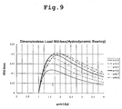
- load-carrying capacity is a term of a bearing and has dimension of force
- load-carrying capacity is a term of a bearing and has dimension of force
- the load-carrying capacity varies according to the configuration of the groove for hydrodynamic bearing. That is, the distance between the impeller and the surrounding parts varies according to the configuration of the groove for hydrodynamic bearing. Therefore the designing of the configuration of the groove for hydrodynamic bearing is important
- the principal object is to increase the load-carrying capacity.
- a logarithmic spiral groove is conventionally adopted.
- it is important to prevent the hemolysis to a high extent in addition to making the load-carrying capacity high.
- load-carrying capacity is a term of a bearing and has dimension of force
- load-carrying capacity is a term of a bearing and has dimension of force
- the centrifugal fluid pump apparatus 1 has the control mechanism 6 and the pump body 5 including the pump section 2 having the impeller 21 rotating in the housing 20; the rotor 31 having a magnet 33 for attracting the impeller 21 thereto; a motor 34 for rotating the rotor 31; the electromagnet 41 for attracting the impeller 21 thereto, the sensor 42 for detecting the position of the impeller 21, and the groove 38 for hydrodynamic bearing provided on the inner surface of the housing 20.
- the control mechanism 6 has the position sensor output monitoring function 56, the electromagnet current monitoring function 57, and the motor current monitoring function.
- the centrifugal fluid pump apparatus 1 further includes the emergency impeller rotation function that operates when the failure detection function has detected that the sensor or the electromagnet has a failure to rotate the impeller 21 by utilizing the groove 38 for hydrodynamic bearing.
- the impeller In the hydrodynamic pressure bearing pump, the impeller is kept out of contact with the housing in blood. However, in the pump apparatus disclosed in the patent document 1, it is impossible to find the position of the impeller. Thus it is impossible to check whether the impeller is rotating without contacting the inner surface of the housing with a predetermined interval kept between the impeller and the inner surface of the housing.
- the groove for hydrodynamic bearing of the pump apparatus disclosed in the patent document 2 is used for an emergency such as the failure of the sensor and not of the type of rotating the impeller by always using the hydrodynamic pressure generated by the groove for hydrodynamic bearing.
- the sensor does not measure the position of the impeller when the impeller is rotated without contacting the housing by the hydrodynamic pressure generated by the groove for hydrodynamic bearing.
- the first object described above is attained by the following a centrifugal fluid pump apparatus.
- a centrifugal blood pump apparatus comprises a housing having a blood inlet port and a blood outlet port; a centrifugal pump section including an impeller having a magnetic material and rotating inside said housing to feed a fluid by a centrifugal force generated during a rotation thereof; an impeller rotational torque generation section for attracting thereto said impeller of said centrifugal pump section and rotating said impeller; and a portion, in which a groove for hydrodynamic bearing is formed, provided on an inner surface of said housing at a side of said impeller rotational torque generation section or a surface of said impeller at said side of said impeller rotational torque generation section, said impeller being rotated by said groove for hydrodynamic bearing without contacting said housing, wherein a plurality of grooves for hydrodynamic bearing is formed on said portion in which a groove for hydrodynamic bearing is formed; each of said grooves for hydrodynamic bearing has a first side and a second side both extending from a periphery of said portion in which a groove for hydrodynamic bearing is formed toward a central side
- the first object described above is attained by the following a centrifugal fluid pump apparatus.
- a centrifugal blood pump apparatus comprises a housing having a blood inlet port and a blood outlet port; a centrifugal pump section including an impeller having a magnetic material and rotating inside said housing to feed a fluid by a centrifugal force generated during a rotation thereof; an impeller rotational torque generation section for attracting thereto said impeller of said centrifugal pump section and rotating said impeller; and a portion, in which a groove for hydrodynamic bearing is formed, provided on an inner surface of said housing at a side of said impeller rotational torque generation section or a surface of said impeller at a side of said impeller rotational torque generation section, said impeller being rotated by said groove for hydrodynamic bearing without contacting said housing, wherein a plurality of grooves for hydrodynamic bearing is formed on said portion in which a groove for hydrodynamic bearing is formed; each of said grooves for hydrodynamic bearing has a first side and a second side both extending from a periphery of said portion in which a groove for hydrodynamic bearing is formed toward a central
- a blood pump apparatus comprises a housing having a blood inlet port and a blood outlet port; a pump section including an impeller having a magnetic material disposed therein and rotating in said housing to feed blood; and an impeller rotational torque generation section for attracting thereto said impeller of said pump section and rotating said impeller, wherein said pump section further comprises a groove for hydrodynamic bearing provided on an inner surface of said housing at a side of said impeller rotational torque generation section or a surface of said impeller at said side of said impeller rotational torque generation section, said impeller being rotated by said groove for hydrodynamic bearing without contacting said housing, wherein said pump section further comprises a sensor for measuring a position of said impeller when said impeller is rotated without contacting said housing by a hydrodynamic pressure generated by said groove for hydrodynamic bearing.
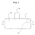
- Fig. 1 is a front view showing a centrifugal blood pump apparatus according to an embodiment of the present invention.
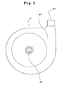
- Fig. 2 is a plan view showing the centrifugal blood pump apparatus shown in Fig. 1.
- Fig. 3 is a vertical sectional view showing the centrifugal blood pump apparatus of the embodiment shown in Fig. 1.
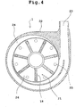
- Fig. 4 is a sectional view, taken along a line A-A in Fig. 1, showing the centrifugal blood pump apparatus.
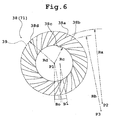
- Fig. 5 is a sectional view showing a state in which an impeller is removed from the sectional view, taken along a line A-A in Fig. 1, showing the centrifugal blood pump apparatus.
- a centrifugal blood pump apparatus 1 of the present invention includes a housing 20 having a blood inlet port 22 and a blood outlet port 23; a centrifugal pump section 2 including an impeller 21 having a magnetic material 25 disposed therein and rotating inside the housing 20 to feed a fluid by a centrifugal force generated during its rotation; an impeller rotational torque generation section 3 for attracting thereto the magnetic material 25 of the impeller 21 of the centrifugal pump section 2 and rotating the impeller 21; and a groove 38 for hydrodynamic bearing (hereinafter referred to as hydrodynamic bearing groove) provided on an inner surface of the housing 20 at the side of the impeller rotational torque generation section 3 thereof or a surface of the impeller 21 at the side of the impeller rotational torque generation section 3 thereof.
- hydrodynamic bearing groove for hydrodynamic bearing
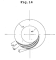
- each hydrodynamic bearing groove 38 has a first side 38a and a second side 38b both extending from the periphery of a portion 39 in which a groove for hydrodynamic bearing is formed toward the central side thereof and opposed to each other, a third side 38c connecting one end of the first side 38a and one end of the second side 38b to each other, and a fourth side 38d connecting the other end of the first side 38a and the other end of the second side 38b to each other.
- the first side 38a and the second side 38b are formed as a circular arc respectively in such a way that the centers of the circular arcs are different from each other.
- a value relating to a groove depth ratio a (a h1/h2) computed from a distance h1 between the impeller 21 and the housing 20 in the hydrodynamic bearing groove of the portion in which a hydrodynamic bearing groove is formed during a rotation of the impeller 21 and from a distance h2 between the impeller 21 and the housing 20 in the hydrodynamic bearing groove-non-present portion (in other words, land region) of the portion in which a hydrodynamic bearing groove is formed during the rotation of the impeller 21 is in the range of 1.5 to 2.5.
- the hydrodynamic bearing groove-non-present portion is said in other words as land region.
- the hydrodynamic bearing groove 38 is capable of obtaining a load-carrying capacity almost equal to that of a logarithmic groove for hydrodynamic bearing.
- the hydrodynamic bearing groove 38 is wider and shallower than the logarithmic groove for hydrodynamic bearing having the same number of grooves, the hydrodynamic bearing groove 38 generates a less amount of hemolysis.
- the hydrodynamic bearing groove 38 has the first side 38a and the second side 38b both extending from the periphery of the portion 39 thereof in which a hydrodynamic bearing groove is formed toward the central side thereof and opposed to each other, the third side 38c connecting one end of the first side 38a and one end of the second side 38b to each other, and the fourth side 38d connecting the other end of the first side 38a and the other end of the second side 38b to each other.
- the first side 38a and the second side 38b are formed as the circular arc respectively in such a way that the centers of the circular arcs are different from each other.
- four corners 38e, 38f, 38g, and 38h composed of the four sides 38a, 38b, 38c, and 38d are rounded.
- the area of the hydrodynamic bearing groove whose corners are rounded is smaller than the hydrodynamic bearing groove whose corners are not rounded, although the load-carrying capacity of the corner-rounded hydrodynamic bearing grooves decreases slightly.
- the corner-rounded hydrodynamic bearing groove does not have a portion where a pressure is excessively high.
- the corner-rounded hydrodynamic bearing groove gives a smaller damage to blood than the hydrodynamic bearing groove whose corners are not rounded and further causes blood to stagnate to a lower extent than the hydrodynamic bearing groove whose corners are not rounded. Therefore the corner-rounded hydrodynamic bearing groove causes generation of hemolysis and thrombus to a lower extent than the hydrodynamic bearing groove whose corners are not rounded because the former causes blood to stagnate to a lower extent than the latter.
- the four corners of the hydrodynamic bearing groove are rounded at not less than 0.1mm. Thereby the hydrodynamic bearing groove causes the hemolysis to occur to a lower extent.
- the third side and the fourth side are formed as a circular arc respectively in such a way that the circular arcs have the same center and different radii. Thereby the hydrodynamic bearing groove is readily machinable.
- the centrifugal blood pump apparatus 1 of the present invention has both the first and second aspects.
- the centrifugal blood pump apparatus will be described below by using an embodiment having both the first and second aspects.
- the centrifugal blood pump apparatus 1 the impeller is rotated not with the impeller magnetically levitated but with the impeller out of contact with the housing by means of the hydrodynamic bearing groove.
- This construction eliminates the need for an electromagnet occupying a larger area than other parts used for the magnetic levitation of the impeller.
- the centrifugal blood pump apparatus 1 has the housing 20 having the blood inlet port 22 and the blood outlet port 23; the centrifugal pump section 2 having the impeller 21 rotating inside the housing 20 to feed blood by a centrifugal force generated during its rotation; and the impeller rotational torque generation section 3 for the impeller 21.
- the impeller rotational torque generation section 3 has a rotor 31 having a magnet 33 for attracting thereto the magnetic material 25 of the impeller 21; and a motor 34 for rotating the rotor 31.
- the impeller 21 rotates without contacting the inner surface of the housing 20 by a pressure generated by the hydrodynamic bearing groove 38 when the impeller 21 rotates.
- the housing 20 has the blood inlet port 22 and the blood outlet port 23 and is formed of a non-magnetic material.
- the housing 20 accommodates a blood chamber 24 communicating with the blood inlet port 22 and the blood outlet port 23.
- the housing 20 also accommodates the impeller 21 therein.
- the blood inlet port 22 projects substantially vertically from the vicinity of the center of the upper surface of the housing 20.
- the blood inlet port 22 does not necessarily have to be formed as a straight pipe, but may be formed as a curved pipe or a bent pipe. As shown in Figs. 2 and 4, the blood outlet port 23 projects tangentially from the side surface of the approximately cylindrical housing 20.
- the disc-shaped impeller 21 having a through-hole in the center thereof is accommodated inside the blood chamber 24 formed inside the housing 20.
- the impeller 21 includes an annular plate-shaped member (lower shroud) 27 forming the lower surface thereof, an annular plate-shaped member (upper shroud) 28 forming the upper surface thereof and opening at the center thereof, and a plurality of (for example, seven) vanes 18 formed between the lower shroud 27 and the upper shroud 28.
- a plurality of (for example, seven) blood passages 26 partitioned from one another by the adjacent vanes 18 is formed between the lower shroud 27 and the upper shroud 28.
- each of the blood passages 26 communicates with the center opening of the impeller 21 and extends from the center opening of the impeller 21 to its periphery, with each of the blood passages 26 becoming gradually larger in the width thereof.
- the vanes 18 are formed between the adjacent blood passages 26.
- the vanes 18 and blood passages 26 are spaced at equiangular intervals respectively and formed in substantially the same shape respectively.
- a plurality (for example, 10 to 40) of the magnetic materials 25 are embedded in the impeller 21.
- the magnetic materials 25 are embedded in the lower shroud 27 of the impeller 21.
- a permanent magnet 33 to be described later, provided in the rotor 31 of the rotational torque generation section 3 attracts the magnetic material 25 embedded in the impeller 21 toward the side opposite to the side where the blood inlet port 22 is disposed to allow the impeller 21 and the rotor 31.
- the magnetic material 25 serves as a means for allowing to be magnetically coupled to each other and transmitting the rotational torque from the rotational torque generation section 3 to the impeller 21.
- the magnetic coupling, to be described later, between the impeller 21 and the rotor 31 is ensured by embedding a plurality of the magnetic materials 25 (permanent magnet) in the impeller 21. It is preferable that each of the magnetic materials 25 is circular.
- the rotational torque generation section 3 has the rotor 31 accommodated in the housing 20 and the motor 34 for rotating the rotor 31.
- the rotor 31 has a plurality of permanent magnets 33 disposed on a surface thereof at the side of the centrifugal pump section 2.
- the center of the rotor 31 is fixedly secured to the rotational shaft of the motor 34.
- a plurality of the permanent magnets 33 is equiangularly distributed in accordance with the arrangement mode (number and position) of the permanent magnets 25 of the impeller 21.
- the permanent magnet of the impeller In the coupling between the permanent magnet of the impeller and that of the motor, it is preferable to dispose the permanent magnet in such a way that an attractive force is generated between the impeller and the motor even though they are uncoupled from each other by an external force and a power swing occurs therebetween. Thereby even though the impeller and the motor are uncoupled from each other and the power swing occurs therebetween, they can be coupled to each other easily again because the attractive force is present therebetween.
- the housing 20 accommodates the impeller 21 and has the groove 38 for hydrodynamic bearing formed on an inner surface 20a of the housing 20, at the rotor-disposed side, forming the blood chamber 24.
- a hydrodynamic bearing effect generated between the groove 38 for hydrodynamic bearing and the impeller 21 by a rotation of the impeller 21 at a speed more than a predetermined number of rotations allows the impeller 21 to rotate without contacting the inner surface of the housing 20.
- the groove 38 for hydrodynamic bearing has a size corresponding to that of the bottom surface (surface at rotor side) of the impeller 21.
- the groove 38 for hydrodynamic bearing extends spirally (in other words, curved) outwardly to the vicinity of the outer edge of the inner surface 20a, with one end of the groove 38 for hydrodynamic bearing disposed on the periphery (circumference) of a circle spaced outward at a short distance from the center of the inner surface 20a of the housing 20 and with the width thereof becoming outwardly gradually larger.
- a plurality of the grooves 38 for hydrodynamic bearing has substantially the same configuration and is spaced at almost equal intervals.
- Each of the grooves 38 for hydrodynamic bearing is concavely formed. It is preferable that the depth thereof is in the range of 0.05 to 0.4mm.
- the number of the groove 38 for hydrodynamic bearing is favorably in the range of 6 to 36 and more favorably in the range of 8 to 24.
- 18 grooves 38 for hydrodynamic bearing are provided at equiangular intervals around the axis of the impeller 21.
- the groove 38 for hydrodynamic bearing may be disposed on the rotor-side surface of the impeller 21 instead of disposing it at the housing side. It is preferable that the groove 38 for hydrodynamic bearing disposed on the rotor-side surface of the impeller 21 has the same construction as that of the groove 38 for hydrodynamic bearing disposed at the housing side.
- the groove 38 for hydrodynamic bearing having the above-described construction is attracted toward the impeller torque generation section 3. Owing to the hydrodynamic bearing effect generated between the groove 38 for hydrodynamic bearing disposed on the housing and the bottom surface of the impeller 21 (or between the groove 38 for hydrodynamic bearing disposed on the impeller and the inner surface of the housing), the impeller 21 rotates without contacting the inner surface of the housing 20 with the impeller 21 levitating slightly from the inner surface of the housing 20, thus providing a blood passage between the lower surface of the impeller 21 and the inner surface of the housing 20. Thereby it is possible to prevent blood from staying therebetween and thrombus from occurring because the blood is prevented from staying therebetween.
- the hydrodynamic bearing groove 38 has the first side 38a and the second side 38b both extending from the periphery of the portion 39 thereof in which a hydrodynamic bearing groove is formed toward the central side thereof and opposed to each other, the third side 38c connecting one end of the first side 38a and one end of the second side 38b to each other, and the fourth side 38d connecting the other end of the first side 38a and the other end of the second side 38b to each other.
- the first side 38a and the second side 38b are formed as a circular arc respectively in such a way that the centers of the circular arcs are different from each other.
- the first side 38a and the second side 38b are composed of a circular arc respectively in such a way that the circular arcs have different centers and radii.
- the hydrodynamic bearing groove may be composed of circular arcs having the same center and different radii or different centers and the same radius.
- the hydrodynamic bearing groove composed of circular arcs having different centers and radii can be provided with a larger width in the peripheral portion of the portion thereof in which a hydrodynamic bearing groove is formed thereof than the hydrodynamic bearing groove composed of circular arcs having the same center and different radii or the hydrodynamic bearing groove composed of different centers and the same radius.
- the third side 38c and the fourth side 38d are formed as a circular arc respectively in such a way that the circular arcs have the same center and different radii.
- the first side 38a is formed as the circular arc having a radius Ra and a center disposed at a point P2 located outside the portion 39 in which a hydrodynamic bearing groove is formed.
- the second side 38b is formed as the circular arc having a radius Rb and a center disposed at a point P3 located outside the portion 39 in which a hydrodynamic bearing groove is formed.
- the radius Ra varies according to the size of the blood pump apparatus, the radius Ra is set to preferably in the range of 30 to 70mm.
- the radius Rb varies according to the size of the blood pump apparatus, the radius Rb is set to preferably in the range of 30 to 70mm. It is preferable that the distance between the points P2 and P3 is set to the range of 3 to 10mm.
- the third side 38c is formed as the circular arc having a radius Rc and a center disposed at a center P1 of the portion 39 in which a hydrodynamic bearing groove is formed.
- the fourth side 38d is formed as the circular arc having a radius Rd and a center disposed at the center P1 of the portion 39 in which a hydrodynamic bearing groove is formed.
- the radius Rc varies according to the size of the blood pump apparatus, the radius Rc is set to preferably in the range of 6 to 18mm.
- the radius Rd varies according to the size of the blood pump apparatus, the radius Rd is set to preferably in the range of 15 to 30mm. It is preferable that the radius Rc is 0.3 to 0.8 times the radius Rd.
- the hydrodynamic bearing groove 38 composed of the four sides 38a, 38b, 38c, and 38d, four corners 38e, 38f, 38g, and 38h are rounded.
- the four corners of said groove for hydrodynamic bearing are rounded at not less than 0.1mm.
- the load-carrying capacity can be computed, supposing that the outer radius of the groove is r2, the inner radius thereof is rb, the fluid inlet angle of the groove is ⁇ , the ratio of the width of the groove to that of the land is a1/a2, the number of grooves is N, the depth of the groove is h1, the number of rotations is ⁇ , and the viscosity is ⁇ .
- the impeller maintains its position without contacting the periphery thereof inside the housing with the force of (1) and that of (2) kept in balance.
- a pressure p is computed as follows:
- Fig. 9 indicates that there is (efficient) s (B o/ B) which provides a maximum load-carrying capacity for desired h 1 and h 2 . Therefore it is possible to obtain a sufficient load-carrying capacity by appropriately setting h 1 , h 2 , B, B o , and L which are parameters of the configuration of the hydrodynamic bearing groove.
- the outer and inner diameters of the impeller are designated.
- Fig. 5 shows the final configuration of the groove.
- a centrifugal blood pump apparatus according to another embodiment of the present invention is described below.
- Fig.10 is a front view showing a centrifugal blood pump apparatus according to another embodiment of the present invention.
- Fig. 11 is a vertical sectional view showing the centrifugal blood pump apparatus of the embodiment shown in Fig. 10.
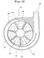
- Fig. 12 is a sectional view, taken along a line B-B in Fig. 10, showing the centrifugal blood pump apparatus.
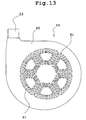
- Fig. 13 is a bottom view showing the centrifugal blood pump apparatus shown in Fig. 10.
- a plan view of the centrifugal blood pump apparatus according to the embodiment shown in Fig. 10 is the same as the plan view shown in Fig. 2.
- a sectional view showing the impeller removed from a sectional view taken along a line B-B in Fig. 10 is the same as the sectional view shown in Fig. 5. Therefore they are omitted herein.
- a pump apparatus 50 of this embodiment is different from the pump apparatus 1 of the above-described embodiment in only the mechanism of the impeller rotational torque generation section 3.
- the impeller rotational torque generation section 3 of the pump apparatus 50 does not have a rotor, but is of a type of driving the impeller directly.
- the impeller 21 rotates without contacting the inner surface of the housing 20 by a pressure generated by the hydrodynamic bearing groove 38 when the impeller 21 rotates.
- the mode of the hydrodynamic bearing groove 38 is the same as that of the above-described embodiment.
- the impeller rotational torque generation section 3 of the pump apparatus 50 has a plurality of stator coils 61 accommodated in the housing 20.
- the stator coils 61 are disposed along a circumference at equiangular intervals around the axis thereof. More specifically, six stator coils 61 are used. Multilayer stator coils are used as the stator coils 61.
- a rotating magnetic field is generated by switching the direction of electric current flowing through each stator coil 61. The impeller is attracted by the rotating magnetic field and rotates.
- a plurality (for example, 6 to 12) of the magnetic materials 25 is embedded in the impeller 21.
- the magnetic materials 25 are embedded in the lower shroud 27.
- the stator coils 61 provided in the rotational torque generation section 3 attracts the magnetic material 25 embedded in the impeller toward the side opposite to the side where the blood inlet port 22 is disposed. In this operation, the magnetic materials 25 couple to the operation of the stator coils 61 and transmit the rotational torque from the rotational torque generation section 3 to the impeller 21.
- the magnetic coupling, to be described later, between the impeller 21 and the stator rotor 61 is ensured by embedding a plurality of the magnetic materials 25 (permanent magnet) in the impeller 21. It is preferable that each of the magnetic materials 25 is approximately trapezoidal.
- the magnetic materials 25 are ring-shaped or plate-shaped. It is preferable that the number and arrangement mode of the magnetic materials 25 correspond to those of the stator coils 61.
- the magnetic materials 25 are disposed circumferentially at equiangular intervals around the axis of the impeller in such a way that positive and negative poles thereof alternate with each other.
- Fig. 16 is a block diagram of an embodiment including a control mechanism of a blood pump apparatus of the present invention.
- Fig.17 is a front view showing a blood pump apparatus according to still another embodiment of the present invention.
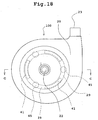
- Fig. 18 is a plan view showing the blood pump apparatus shown in Fig. 17.
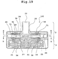
- Fig.19 is a sectional view taken along a line C-C in Fig. 18.
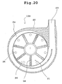
- Fig. 20 is a sectional view taken along a line D-D in Fig. 19.
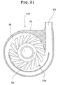
- Fig. 21 is a sectional view showing a state in which an impeller is removed from the sectional view taken along a line D-D in Fig. 19.
- Fig. 22 is a sectional view showing a state in which an impeller is removed from the sectional view taken along a line E-E in Fig. 19.
- a blood pump apparatus 100 of the present invention includes a housing 20 having a blood inlet port 22 and a blood outlet port 23; a pump section 2 including an impeller 21 having a magnetic material 25 disposed therein and rotating in the housing 20 to feed blood; and an impeller rotational torque generation section 3 for attracting thereto the impeller 21 of the pump section 2 and rotating the impeller 21.
- the pump section 2 further includes a first groove 38 for hydrodynamic bearing provided on an inner surface of the housing 20 at the side of the impeller rotational torque generation section 3 or a surface of the impeller 21 at the side of the impeller rotational torque generation section 3.
- the impeller 21 rotates without contacting the housing 20.
- the pump section 2 has a sensor 45 having a function of measuring the position of the impeller 21 when the impeller 21 is rotated without contacting the housing 20 by a hydrodynamic pressure generated by the hydrodynamic bearing groove 38.
- the impeller is rotated without contacting the housing 20 by utilizing the hydrodynamic bearing groove, and the position of the impeller can be checked.
- the blood pump apparatus 100 of this embodiment is a centrifugal blood pump apparatus and has the housing 20 having the blood inlet port 22 and the blood outlet port 23, the centrifugal pump section 2 having the impeller 21 rotating inside the housing 20 to feed blood by a centrifugal force generated during its rotation, and the impeller rotational torque generation section 3 for the impeller 21.
- the blood pump apparatus of the embodiment of the present invention is not limited to the above-described centrifugal pump apparatus.
- the blood pump apparatus may be of an axial-flow type or of a diagonal-flow type.
- the impeller rotational torque generation section 3 has a rotor 31 having a magnet 33 for attracting thereto a magnetic material 25 of the impeller 21 and a motor 34 for rotating the rotor 31.
- the impeller 21 rotates without contacting the inner surface of the housing 20 by a pressure generated by the hydrodynamic bearing groove when the impeller 21 rotates.
- the housing 20 has the blood inlet port 22 and the blood outlet port 23 and is formed of a non-magnetic material.
- the housing 20 accommodates a blood chamber 24 communicating with the blood inlet and outlet ports 22 and 23.
- the housing 20 also accommodates the impeller 21 therein.
- the blood inlet port 22 projects substantially vertically from the vicinity of the center of the upper surface of the housing 20.
- the blood inlet port 22 does not necessarily have to be formed as a straight pipe, but may be formed as a curved pipe or a bent pipe. As shown in Figs. 18, 20, 21, and 22, the blood outlet port 23 projects tangentially from a side surface of the approximately cylindrical housing 20.
- the disc-shaped impeller 21 having a through-hole in the center thereof is accommodated inside the blood chamber 24 formed inside the housing 20.
- the impeller 21 includes an annular plate-shaped member (lower shroud) 27 forming the lower surface thereof, an annular plate-shaped member (upper shroud) 28 forming the upper surface thereof and opening at the center thereof, and a plurality of (for example, seven) vanes 18 formed between the lower shroud 27 and the upper shroud 28.
- a plurality (for example, seven) of blood passages 26 partitioned from one another by the adjacent vanes 18 is formed between the lower shroud 27 and the upper shroud 28.
- each of the blood passages 26 communicates with the center opening of the impeller 21 and extends from the center opening of the impeller 21 to its periphery, with each of the blood passages 26 becoming gradually larger in the width thereof.
- each vane 18 is formed between the adjacent blood passages 26.
- the vanes 18 and blood passages 26 are spaced at equiangular intervals respectively and formed in substantially the same shape respectively.
- a plurality (for example, 10 to 40) of the magnetic materials 25 are embedded in the impeller 21.
- the magnetic materials 25 are embedded in the lower shroud 27.
- the magnetic material 25 serves as a means for allowing the impeller 21 and the rotor 31 to be magnetically coupled to each other and transmitting the rotational torque from the rotational torque generation section 3 to the impeller 21.
- the magnetic coupling, to be described later, between the impeller 21 and the rotor 31 is ensured by embedding a plurality of the magnetic materials 25 (permanent magnet) in the impeller 21. It is preferable that each of the magnetic materials 25 is circular.
- the rotor 31 accommodated in the housing 20 and a motor 34 for rotating the rotor 31.
- the rotor 31 has a plurality of permanent magnets 33 disposed on a surface thereof at the side of the centrifugal pump section 2.
- the center of the rotor 31 is fixedly secured to the rotational shaft of the motor 34.
- a plurality of the permanent magnets 33 is equiangularly distributed in accordance with the arrangement mode (number and position) of the permanent magnets 25 of the impeller 21.
- the permanent magnet of the impeller In the coupling between the permanent magnet of the impeller and that of the motor, it is preferable to dispose the permanent magnet in such a way that an attractive force is generated between the impeller and the motor even though they are uncoupled from each other by an external force and a power swing occurs therebetween. Thereby even though the impeller and the motor are uncoupled from each other and the .power swing occurs therebetween, they can be coupled to each other easily again because the attractive force is present therebetween.
- the impeller 21 has a plurality of a ring-shaped permanent magnet 29.
- the permanent magnet 29 is embedded in the upper shroud 28.
- a second permanent magnet 41 attracts the permanent magnet 29 embedded in the impeller toward the side opposite to the side where the impeller rotational torque generation section 3 (namely, rotor) is disposed.
- the permanent magnet 29 is so disposed that an attractive force is generated between the permanent magnet 29 and the second permanent magnet 41.
- the permanent magnet 29 may be plural (for example, 10 to 40) provided.
- the housing 20 accommodates the impeller 21 and has the first groove 38 for hydrodynamic bearing formed on a rotor-side inner surface 20a of the housing 20 forming the blood chamber 24.
- a hydrodynamic bearing effect generated between the first groove 38 for hydrodynamic bearing and the impeller 21 by a rotation of the impeller 21 at a speed more than a predetermined number of rotations allows the impeller 21 to rotate without contacting the inner surface of the housing 20.
- the centrifugal pump section 2 has at least one fixed permanent magnet 41 for attracting thereto the magnetic material 29 (embedded in upper shroud 28) of the impeller 21 provided separately from the magnetic material 25 of the impeller 21. More specifically, as shown with broken lines in Fig. 18, the circular arc-shaped permanent magnet 41 is plural used.
- the impeller 21 is attracted to opposite directions by the permanent magnet 33 of the rotor 31 and the permanent magnet 41.
- the permanent magnets 41 are provided at equiangular intervals around the axis of the impeller 21. It is possible to use not less than three permanent magnets 41, for example, four permanent magnets 41.
- the blood pump section 2 has a sensor 45 having a function of measuring the position of the impeller 21. More specifically, the blood pump section 2 has a plurality of position sensors 45 accommodated in the housing 20.
- the position sensors (three) 45 are spaced at equiangular intervals around the axis of the impeller 21.
- the electromagnets 41 are also spaced at equiangular intervals around the axis of the impeller 21.
- the position sensors 45 detect the gap between them and the magnetic material 29. As shown in Fig. 16, outputs of the position sensors 45 are transmitted to a control part 51 of the control unit 6 controlling motor current.
- the control unit 6 has a sensor unit 57 for the sensors 45, the control part 51, a power amplifier 52 for the motor, a motor control circuit 53, and a motor current monitoring part 55.
- the blood pump apparatus has a blood viscosity-computing function of computing a blood viscosity by using the output of the position sensor 45. More specifically, the control unit 6 has a viscosity-measuring function.
- the blood viscosity-computing function includes a function of temporarily decreasing the number of rotations of the impeller to a predetermined number of rotations; and a function of detecting a vertical swivel length of the impeller by using the output of the sensor when the number of rotations of the impeller has decreased to the predetermined number of rotations by the function of temporarily decreasing the number of rotations and computing the blood viscosity by using the detected vertical swivel length.
- the blood viscosity-computing function has a storing part for storing data of the relationship between the vertical swivel length of the impeller and the blood viscosity at the predetermined number of rotations of the impeller or a viscosity-computing equation obtained from the data of the relationship and a viscosity-computing function for computing the blood viscosity from data of the vertical swivel length obtained by the output of the sensor and the data of the relationship between the vertical swivel length of the impeller and the blood viscosity stored by the storing part or the viscosity-computing equation.
- the control unit 6 has the function of temporarily decreasing the number of rotations of the motor to a predetermined number of rotations by adjusting motor current, stores relation data for various blood viscosities between vertical swivel movements (indicated by ⁇ m peak to peak in vertical swivel movement of the impeller) of the impeller at predetermined number of rotations of the motor and blood viscosity, and has the function of computing the blood viscosity from results detected by the sensor and the number of rotations of the motor.
- the output of the position sensor 45 fluctuates like a sine wave in a period (for example, 0.05 seconds at 1200 rpm) of the number of rotations of the motor.
- the peak to peak of the sine wave indicates the vertical swivel of the impeller.
- the vertical swivel is as shown in table 1 when the centrifugal hydrodynamic bearing pump has the impeller having a diameter of 40mm.
- the state of the blood outlet port is shown in conditions of "Open” and “Close” normally used for a pump.
- the vertical swivel length is reduced by the display of the hydrodynamic pressure effect at the blood inlet port.
- This relationship is measured in advance for a plurality of viscosities (for example, intervals of 1 mPa ⁇ s at 2 to 5 mPa s) at predetermined number of rotations (for example, 800 to 1200 rpm) of the impeller, and in addition, data of results of the measurement or relational expression data obtained from the data of results of the measurement is stored. Thereafter the viscosity of the blood is computed from a measured value of the vertical swivel and the above-described data.
- the vertical swivel varies to some extent in dependence on the state of the blood outlet port.
- the pump apparatus 100 of the present invention has the first groove 38 for hydrodynamic bearing provided on an inner surface of the housing 20 at the side of the impeller rotational torque generation section 3 thereof or a surface of the impeller 21 at the side of the impeller rotational torque generation section 3 thereof.
- the first groove 38 for hydrodynamic bearing has a size corresponding to that of the bottom surface (surface at rotor side) of the impeller 21.
- the first groove 38 for hydrodynamic bearing extends spirally (in other words, curved) outwardly to the vicinity of the outer edge of the inner surface 20a, with one end of the first groove 38 for hydrodynamic bearing disposed on the periphery (circumference) of a circle spaced outward at a short distance from the center of the inner surface 20a of the housing 20 and with the width thereof becoming outwardly gradually larger.
- the first groove 38 for hydrodynamic bearing is composed of a group of a large number of grooves for hydrodynamic bearing.
- the first grooves 38 have substantially the same configuration and are spaced at almost equal intervals.
- Each of the first grooves 38 for hydrodynamic bearing is concavely formed. It is preferable that the depth thereof is in the range of 0.05 to 0.4mm.
- the number of the first grooves 38 for hydrodynamic bearing is favorably in the range of 6 to 36. In the embodiment, 16 grooves for hydrodynamic bearing are provided at equiangular intervals around the axis of the impeller 21.
- the groove for hydrodynamic bearing may be disposed on the rotor-side surface of the impeller 21 instead of disposing it at the housing side. It is preferable that the groove for hydrodynamic bearing disposed on the rotor-side surface of the impeller 21 has the same construction as that of the groove for hydrodynamic bearing disposed at the housing side.
- the first groove 38 for hydrodynamic bearing is attracted toward the impeller torque generation section 3. Owing to the hydrodynamic bearing effect generated between the first groove 38 for hydrodynamic bearing disposed on the housing and the bottom surface of the impeller 21 (or between the first groove 38 for hydrodynamic bearing disposed on the impeller and the inner surface of the housing), the impeller 21 rotates without contacting the inner surface of the housing 20 with the impeller 21 levitating slightly from the inner surface of the housing 20, thus providing a blood passage between the lower surface of the impeller 21 and the inner surface of the housing 20. Thereby it is possible to prevent blood from staying therebetween and thrombus from occurring because the blood is prevented from staying therebetween.
- each hydrodynamic bearing groove 38 has a first side 38a and a second side 38b both extending from the periphery of the portion 39 thereof in which a hydrodynamic bearing groove is formed toward the central side thereof and opposed to each other, a third side 38c connecting one end of the first side 38a and one end of the second side 38b to each other, and a fourth side 38d connecting the other end of the first side 38a and the other end of the second side 38b to each other.
- the first side 38a and the second side 38b are formed as a circular arc respectively in such a way that the centers of the circular arcs are different from each other.
- the first side 38a and the second side 38b are composed of a circular arc respectively in such a way that the circular arcs have different centers and radii.
- the hydrodynamic bearing groove may be composed of circular arcs having the same center and different radii or different centers and the same radius.
- the hydrodynamic bearing groove composed of circular arcs having different centers and radii can be provided with a larger width in the peripheral portion of the portion in which a hydrodynamic bearing groove is formed thereof than the hydrodynamic bearing groove composed of circular arcs having the same center and different radii or the hydrodynamic bearing groove composed of different centers and the same radius.
- the third side 38c and the fourth side 38d are formed as a circular arc respectively in such a way that the circular arcs have the same center and different radii.
- the first side 38a is formed as the circular arc having a radius Ra and a center disposed at a point P2 located outside the portion 39 in which a hydrodynamic bearing groove is formed.
- the second side 38b is formed as the circular arc having a radius Rb and a center disposed at a point P3 located outside the portion 39 in which a hydrodynamic bearing groove is formed.
- the radius Ra varies according to the size of the blood pump apparatus, the radius Ra is set to preferably in the range of 30 to 70mm.
- the radius Rb varies according to the size of the blood pump apparatus, the radius Rb is set to preferably in the range of 30 to 70mm. It is preferable that the distance between the points P2 and P3 is set to the range of 3 to 10mm.
- the third side 38c is formed as the circular arc having a radius Rc and a center disposed at a center P1 of the portion 39 in which a hydrodynamic bearing groove is formed.
- the fourth side 38d is formed as the circular arc having a radius Rd and a center disposed at the center P1 of the portion 39 in which a hydrodynamic bearing groove is formed.
- the radius Rc varies according to the size of the blood pump apparatus, the radius Rc is set to preferably in the range of 6 to 18mm.
- the radius Rd varies according to the size of the blood pump apparatus, the radius Rd is set to preferably in the range of 15 to 30mm. It is preferable that the radius Rc is 0.3 to 0.8 times the radius Rd.
- the hydrodynamic bearing groove 38 composed of the four sides 38a, 38b, 38c, and 38d, four corners 38e, 38f, 38g, and 38h are rounded. It is preferable that the four corners are rounded at not less than 0.1mm.
- a second groove 71 for hydrodynamic bearing has a size corresponding to that of the upper surface (surface at permanent magnet side) of the impeller 21.
- the second groove 71 for hydrodynamic bearing extends spirally (in other words, curved) outwardly to the vicinity of the outer edge of the inner surface 20a, with one end of the second groove 71 for hydrodynamic bearing disposed on the periphery (circumference) of a circle spaced outward at a short distance from the center of the inner surface 20a of the housing 20 and with the width thereof becoming outwardly gradually larger.
- a plurality of the grooves 71 for hydrodynamic bearing has substantially the same configuration and is spaced at almost equal intervals.
- Each of the second groove 71 for hydrodynamic bearing is concavely formed. It is preferable that the depth thereof is in the range of 0.05 to 0.4mm.
- the number of the second groove 71 for hydrodynamic bearing is favorably in the range of 6 to 36. In the embodiment, 16 grooves for hydrodynamic bearing are provided at equiangular intervals around the axis of the impeller 21.
- the groove for hydrodynamic bearing may be disposed on the permanent magnet-side surface of the impeller 21 instead of disposing it at the housing side. It is preferable that the groove for hydrodynamic bearing disposed on the permanent magnet-side surface of the impeller 21 has the same construction as that of the groove for hydrodynamic bearing disposed at the housing side.
- the blood pump apparatus 100 has the second hydrodynamic bearing groove 71. Therefore even though the impeller is proximate to a portion of the housing at the side of the second hydrodynamic bearing groove 71 when an excessive hydrodynamic pressure is generated by a disturbance or by the first hydrodynamic bearing groove, it is possible to prevent the impeller from contacting the portion of the housing at the side of the second hydrodynamic bearing groove 71 because a hydrodynamic pressure is generated by the second hydrodynamic bearing groove.
- each hydrodynamic bearing groove 71 has a first side 38a and a second side 38b both extending from the periphery of the portion 39 thereof in which a hydrodynamic bearing groove is formed toward the central side thereof and opposed to each other, a third side 38c connecting one end of the first side 38a and one end of the second side 38b to each other, and a fourth side 38d connecting the other end of the first side 38a and the other end of the second side 38b to each other.
- the first side 38a and the second side 38b are formed as a circular arc respectively in such a way that the centers of the circular arcs are different from each other.
- the first side 38a and the second side 38b are composed of a circular arc respectively in such a way that the circular arcs have different centers and radii.
- the third side 38c and the fourth side 38d are formed as a circular arc respectively in such a way that the circular arcs have the same center and different rad ii.
- a centrifugal blood pump apparatus according to another embodiment of the present invention is described below.
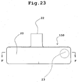
- Fig. 23 is a front view showing a blood pump apparatus according to another embodiment of the present invention.
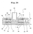
- Fig. 24 is a vertical sectional view showing the blood pump apparatus shown in Fig. 23.
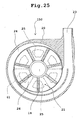
- Fig. 25 is a sectional view, taken along a line F-F in Fig. 23, showing the centrifugal blood pump apparatus.
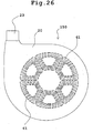
- Fig. 26 is a bottom view showing the centrifugal blood pump apparatus shown in Fig. 23.
- a plan view of the centrifugal blood pump apparatus according to the embodiment shown in Fig. 23 is the same as the plan view shown in Fig.18.
- a pump apparatus 150 of this embodiment is different from the pump apparatus 100 of the above-described embodiment in only the mechanism of the impeller rotational torque generation section 3.
- the impeller rotational torque generation section 3 of the pump apparatus 150 does not have a rotor, but is of a type of driving the impeller directly.
- the impeller 21 rotates without contacting the inner surface of the housing 20 by a pressure generated by the hydrodynamic bearing groove 38 when the impeller 21 rotates.
- the mode of each of a sensor 45, grooves 38, 71 for hydrodynamic bearing, the control unit 6 is the same as that of the above-described embodiments.
- the impeller rotational torque generation section 3 of the pump apparatus 150 has a plurality of stator coils 61 accommodated in the housing 20.
- the stator coils 61 are disposed along a circumference at equiangular intervals around the axis thereof. More specifically, six stator coils 61 are used. Multilayer stator coils are used as the stator coils 61.
- a rotating magnetic field is generated by switching the direction current flowing through each stator coil 61. The impeller is attracted to the rotor by the rotating magnetic field and rotates.
- a plurality (for example, 6 to 12) of the magnetic materials 25 is embedded in the impeller 21.
- the magnetic materials 25 are embedded in the lower shroud 27.
- the stator coils 61 provided in the rotational torque generation section 3 attracts the magnetic material 25 embedded in the impeller toward the side opposite to the side where the blood inlet port 22 is disposed. In this operation, the magnetic materials 25 couple to the operation of the stator coils 61 and transmit the rotational torque from the rotational torque generation section 3 to the impeller 21.
- the magnetic coupling, to be described later, between the impeller 21 and the stator rotor 61 is ensured by embedding a plurality of the magnetic materials 25 (permanent magnet) in the impeller 21. It is preferable that each of the magnetic materials is approximately trapezoidal.
- the magnetic materials 25 are ring-shaped or plate-shaped. It is preferable that the number and arrangement mode of the magnetic materials 25 correspond to those of the stator coils 61.
- the magnetic materials 25 are disposed circumferentially at equiangular intervals around the axis of the impeller in such a way that positive and negative poles thereof alternate with each other.
- the above-described peripheral configuration of the hydrodynamic bearing groove is not limited to the above-described one.
Landscapes
- Engineering & Computer Science (AREA)
- Health & Medical Sciences (AREA)
- Mechanical Engineering (AREA)
- Heart & Thoracic Surgery (AREA)
- Animal Behavior & Ethology (AREA)
- Life Sciences & Earth Sciences (AREA)
- Cardiology (AREA)
- Veterinary Medicine (AREA)
- Anesthesiology (AREA)
- Biomedical Technology (AREA)
- Hematology (AREA)
- Public Health (AREA)
- General Engineering & Computer Science (AREA)
- General Health & Medical Sciences (AREA)
- Fluid Mechanics (AREA)
- Physics & Mathematics (AREA)
- External Artificial Organs (AREA)
- Structures Of Non-Positive Displacement Pumps (AREA)
Applications Claiming Priority (4)
| Application Number | Priority Date | Filing Date | Title |
|---|---|---|---|
| JP2004088108 | 2004-03-24 | ||
| JP2004088108A JP4340178B2 (ja) | 2004-03-24 | 2004-03-24 | 遠心式血液ポンプ装置 |
| JP2004103573A JP4340182B2 (ja) | 2004-03-31 | 2004-03-31 | 血液ポンプ装置 |
| JP2004103573 | 2004-03-31 |
Publications (3)
| Publication Number | Publication Date |
|---|---|
| EP1598087A2 true EP1598087A2 (fr) | 2005-11-23 |
| EP1598087A3 EP1598087A3 (fr) | 2007-04-25 |
| EP1598087B1 EP1598087B1 (fr) | 2010-02-03 |
Family
ID=34934459
Family Applications (1)
| Application Number | Title | Priority Date | Filing Date |
|---|---|---|---|
| EP20050006391 Not-in-force EP1598087B1 (fr) | 2004-03-24 | 2005-03-23 | pompe de sang avec palier hydrodynamique |
Country Status (4)
| Country | Link |
|---|---|
| US (2) | US7748964B2 (fr) |
| EP (1) | EP1598087B1 (fr) |
| AT (1) | ATE456963T1 (fr) |
| DE (1) | DE602005019219D1 (fr) |
Cited By (15)
| Publication number | Priority date | Publication date | Assignee | Title |
|---|---|---|---|---|
| WO2008152425A1 (fr) | 2007-06-14 | 2008-12-18 | Calon Cardio Technology Limited | Pompe rotative axiale à diamètre réduit pour assistance cardiaque |
| EP2538086A1 (fr) * | 2010-02-16 | 2012-12-26 | NTN Corporation | Dispositif de pompe centrifuge |
| EP2719403A1 (fr) * | 2012-10-12 | 2014-04-16 | Abiomed Europe GmbH | Pompe sanguine centrifuge |
| US9556873B2 (en) | 2013-02-27 | 2017-01-31 | Tc1 Llc | Startup sequence for centrifugal pump with levitated impeller |
| US9623161B2 (en) | 2014-08-26 | 2017-04-18 | Tc1 Llc | Blood pump and method of suction detection |
| EP3173110A1 (fr) * | 2015-11-30 | 2017-05-31 | Fundacja Rozwoju Kardiochirurgii Im. Prof. Zbigniewa Religi | Arrangement de suspension pour pompe rotative, en particulier pompe centrifuge d'assistance cardiaque |
| US9759222B2 (en) * | 2013-03-14 | 2017-09-12 | Tc1 Llc | Blood pump rotor bearings |
| US9850906B2 (en) | 2011-03-28 | 2017-12-26 | Tc1 Llc | Rotation drive device and centrifugal pump apparatus employing same |
| EP2554191A4 (fr) * | 2010-03-26 | 2018-04-04 | Thoratec Corporation | Dispositif de pompe sanguine centrifuge |
| US10052420B2 (en) | 2013-04-30 | 2018-08-21 | Tc1 Llc | Heart beat identification and pump speed synchronization |
| US10117983B2 (en) | 2015-11-16 | 2018-11-06 | Tc1 Llc | Pressure/flow characteristic modification of a centrifugal pump in a ventricular assist device |
| US10166318B2 (en) | 2015-02-12 | 2019-01-01 | Tc1 Llc | System and method for controlling the position of a levitated rotor |
| US10245361B2 (en) | 2015-02-13 | 2019-04-02 | Tc1 Llc | Impeller suspension mechanism for heart pump |
| US10371152B2 (en) | 2015-02-12 | 2019-08-06 | Tc1 Llc | Alternating pump gaps |
| US10506935B2 (en) | 2015-02-11 | 2019-12-17 | Tc1 Llc | Heart beat identification and pump speed synchronization |
Families Citing this family (44)
| Publication number | Priority date | Publication date | Assignee | Title |
|---|---|---|---|---|
| JP2004327007A (ja) * | 2003-04-08 | 2004-11-18 | Nec Corp | 光学的情報記録媒体および光学的情報記録再生装置 |
| EP1778981B1 (fr) * | 2004-10-07 | 2008-11-05 | ebm-papst St. Georgen GmbH & Co. KG | Dispositif pour transporter des fluides |
| US20060083642A1 (en) | 2004-10-18 | 2006-04-20 | Cook Martin C | Rotor stability of a rotary pump |
| US8123503B2 (en) * | 2005-09-05 | 2012-02-28 | Tokyo Institute Of Technology | Disposable centrifugal blood pump with magnetic coupling |
| US8672611B2 (en) | 2006-01-13 | 2014-03-18 | Heartware, Inc. | Stabilizing drive for contactless rotary blood pump impeller |
| JP5155186B2 (ja) | 2006-01-13 | 2013-02-27 | ハートウェア、インコーポレイテッド | 回転式血液ポンプ |
| US20070177995A1 (en) * | 2006-02-01 | 2007-08-02 | Yoshio Yano | Pump device |
| US20070183908A1 (en) * | 2006-02-06 | 2007-08-09 | Yoshio Yano | Contactless centrifugal pump |
| JP4898319B2 (ja) * | 2006-06-23 | 2012-03-14 | テルモ株式会社 | 血液ポンプ装置 |
| JP4787726B2 (ja) * | 2006-11-28 | 2011-10-05 | テルモ株式会社 | センサレス磁気軸受型血液ポンプ装置 |
| CN101925748B (zh) * | 2008-01-31 | 2013-01-02 | 国立大学法人横滨国立大学 | 流体机械 |
| JP5171953B2 (ja) | 2008-06-23 | 2013-03-27 | テルモ株式会社 | 血液ポンプ装置 |
| US9314557B2 (en) * | 2008-09-26 | 2016-04-19 | Worldheart Corporation | Magnetically-levitated blood pump with optimization method enabling miniaturization |
| US20100130944A1 (en) * | 2008-11-21 | 2010-05-27 | Music Douglas E | Flow control devices for ophthalmic surgery |
| EP2372160B1 (fr) | 2008-12-08 | 2014-07-30 | Thoratec Corporation | Dispositif de pompage centrifuge |
| JP5378010B2 (ja) | 2009-03-05 | 2013-12-25 | ソラテック コーポレーション | 遠心式ポンプ装置 |
| CN102341600B (zh) | 2009-03-06 | 2014-12-10 | 胸腔科技有限公司 | 离心式泵装置 |
| EP2461465B1 (fr) * | 2009-07-29 | 2018-12-19 | Thoratec Corporation | Dispositif de mise en rotation et dispositif de pompe centrifuge |
| TW201217010A (en) | 2010-06-22 | 2012-05-01 | Thoratec Corp | Apparatus and method for modifying pressure-flow characteristics of a pump |
| US8905910B2 (en) | 2010-06-22 | 2014-12-09 | Thoratec Corporation | Fluid delivery system and method for monitoring fluid delivery system |
| JP5681403B2 (ja) | 2010-07-12 | 2015-03-11 | ソーラテック コーポレイション | 遠心式ポンプ装置 |
| USD669585S1 (en) | 2010-08-20 | 2012-10-23 | Thoratec Corporation | Implantable blood pump |
| JP5577506B2 (ja) | 2010-09-14 | 2014-08-27 | ソーラテック コーポレイション | 遠心式ポンプ装置 |
| EP2617441A4 (fr) * | 2010-09-17 | 2017-12-20 | Thoratec Corporation | Procédé de fabrication de matériel médical destiné à réduire l'adhérence des plaquettes sur une surface en contact avec le sang |
| US9227001B2 (en) | 2010-10-07 | 2016-01-05 | Everheart Systems Inc. | High efficiency blood pump |
| JP6130353B2 (ja) | 2011-04-05 | 2017-05-17 | レスメド・リミテッドResMed Limited | 呼吸装置 |
| JP6083929B2 (ja) | 2012-01-18 | 2017-02-22 | ソーラテック コーポレイション | 遠心式ポンプ装置 |
| WO2014000753A1 (fr) | 2012-06-28 | 2014-01-03 | Rheinisch-Westfälische Technische Hochschule Aachen | Dispositif de pompe sanguine centrifuge |
| US9371826B2 (en) | 2013-01-24 | 2016-06-21 | Thoratec Corporation | Impeller position compensation using field oriented control |
| US10294944B2 (en) | 2013-03-08 | 2019-05-21 | Everheart Systems Inc. | Flow thru mechanical blood pump bearings |
| US9713663B2 (en) | 2013-04-30 | 2017-07-25 | Tc1 Llc | Cardiac pump with speed adapted for ventricle unloading |
| US10001129B2 (en) | 2013-05-23 | 2018-06-19 | Reinheart Gmbh | Impeller of a centrifugal pump apparatus |
| EP4321144A3 (fr) | 2014-07-25 | 2024-04-10 | Kpr U.S., Llc | Système de détection pour appareil de régulation de débit |
| TW201634817A (zh) * | 2015-03-30 | 2016-10-01 | 林聖梁 | 抽水馬達裝置 |
| CN106300722A (zh) * | 2015-05-18 | 2017-01-04 | 德昌电机(深圳)有限公司 | 电机与电动泵 |
| US10177627B2 (en) | 2015-08-06 | 2019-01-08 | Massachusetts Institute Of Technology | Homopolar, flux-biased hysteresis bearingless motor |
| EP3135933B1 (fr) * | 2015-08-25 | 2019-05-01 | ReinHeart GmbH | Palier magnétique actif |
| WO2019125718A1 (fr) | 2017-12-22 | 2019-06-27 | Massachusetts Institute Of Technology | Moteurs de tranches homopolaires sans palier |
| CN111298221A (zh) * | 2018-12-12 | 2020-06-19 | 深圳核心医疗科技有限公司 | 心室辅助装置 |
| EP3795836A1 (fr) * | 2019-09-18 | 2021-03-24 | Levitronix GmbH | Pompe centrifuge et carter de pompe |
| EP4058094A1 (fr) | 2019-11-12 | 2022-09-21 | Fresenius Medical Care Deutschland GmbH | Systèmes de traitement du sang |
| EP4058093A1 (fr) | 2019-11-12 | 2022-09-21 | Fresenius Medical Care Deutschland GmbH | Systèmes de traitement du sang |
| WO2021094144A1 (fr) | 2019-11-12 | 2021-05-20 | Fresenius Medical Care Deutschland Gmbh | Systèmes de traitement du sang |
| CN114728159A (zh) | 2019-11-12 | 2022-07-08 | 费森尤斯医疗护理德国有限责任公司 | 血液治疗系统 |
Citations (2)
| Publication number | Priority date | Publication date | Assignee | Title |
|---|---|---|---|---|
| JPH0491396A (ja) | 1990-07-31 | 1992-03-24 | Ntn Corp | ターボ形ポンプ |
| US6840735B2 (en) | 2002-01-09 | 2005-01-11 | Terumo Kabushiki Kaisha | Centrifugal fluid pump apparatus |
Family Cites Families (24)
| Publication number | Priority date | Publication date | Assignee | Title |
|---|---|---|---|---|
| SE340015B (fr) * | 1969-05-27 | 1971-11-01 | Skf Svenska Kullagerfab Ab | |
| US3620638A (en) * | 1970-08-24 | 1971-11-16 | J Arthur Kaye | Liquid propulsion device |
| JPS6014615A (ja) * | 1983-07-06 | 1985-01-25 | Ebara Corp | スラスト軸受およびその製造方法 |
| JPH04112994A (ja) | 1990-08-31 | 1992-04-14 | Ntn Corp | ターボ形ポンプ |
| JPH04209995A (ja) | 1990-11-30 | 1992-07-31 | Daikin Ind Ltd | 低真空ポンプの軸受構造 |
| US5290236A (en) | 1991-09-25 | 1994-03-01 | Baxter International Inc. | Low priming volume centrifugal blood pump |
| US5350283A (en) * | 1991-12-04 | 1994-09-27 | Ntn Corporation | Clean pump |
| JP3340237B2 (ja) | 1994-04-01 | 2002-11-05 | テイエチケー株式会社 | ポンプ |
| JP2804889B2 (ja) | 1994-08-03 | 1998-09-30 | テイエチケー株式会社 | 動圧軸受ユニット |
| JP3553255B2 (ja) | 1996-01-31 | 2004-08-11 | Ntn株式会社 | 粘度計測機能付磁気浮上型ポンプ |
| US5947703A (en) * | 1996-01-31 | 1999-09-07 | Ntn Corporation | Centrifugal blood pump assembly |
| JP3853865B2 (ja) | 1996-01-31 | 2006-12-06 | テルモ株式会社 | 遠心式血液ポンプ装置 |
| US6071093A (en) * | 1996-10-18 | 2000-06-06 | Abiomed, Inc. | Bearingless blood pump and electronic drive system |
| DE59915262D1 (de) | 1998-07-10 | 2011-06-01 | Levitronix Llc | Verfahren zur Bestimmung des Druckverlustes und des Durchflusses durch eine Pumpe |
| EP0971212B1 (fr) * | 1998-07-10 | 2011-04-20 | Levitronix LLC | Méthode pour déterminer la perte de pression et le débit d'une pompe |
| WO2000064509A1 (fr) * | 1999-04-23 | 2000-11-02 | Ventrassist Pty Ltd | Pompe sanguine rotative et son systeme de commande |
| ATE255685T1 (de) * | 1999-12-27 | 2003-12-15 | Terumo Corp | Flüssigkeitspumpe mit magnetisch aufgehängtem laufrad |
| JP3665549B2 (ja) * | 2000-09-01 | 2005-06-29 | 日本電産株式会社 | スラスト動圧軸受及びこれを備えたスピンドルモータ |
| JP2002227795A (ja) | 2001-01-31 | 2002-08-14 | Ebara Corp | 遠心ポンプ |
| JP2002349468A (ja) | 2001-05-24 | 2002-12-04 | Thk Co Ltd | カスケードポンプ |
| JP3834610B2 (ja) | 2001-07-12 | 2006-10-18 | 独立行政法人産業技術総合研究所 | 動圧軸受を備えた人工心臓ポンプ |
| JP2004052998A (ja) | 2002-05-28 | 2004-02-19 | Mitsubishi Materials Corp | 動圧発生溝を備えた摺動部材及びその製造方法 |
| US7470246B2 (en) | 2002-12-17 | 2008-12-30 | Terumo Kabushiki Kaisha | Centrifugal blood pump apparatus |
| US7128538B2 (en) * | 2003-07-07 | 2006-10-31 | Terumo Corporation | Centrifugal fluid pump apparatus |
-
2005
- 2005-03-23 DE DE200560019219 patent/DE602005019219D1/de active Active
- 2005-03-23 EP EP20050006391 patent/EP1598087B1/fr not_active Not-in-force
- 2005-03-23 AT AT05006391T patent/ATE456963T1/de not_active IP Right Cessation
- 2005-03-24 US US11/087,851 patent/US7748964B2/en not_active Expired - Fee Related
-
2010
- 2010-05-17 US US12/781,254 patent/US8430652B2/en active Active
Patent Citations (2)
| Publication number | Priority date | Publication date | Assignee | Title |
|---|---|---|---|---|
| JPH0491396A (ja) | 1990-07-31 | 1992-03-24 | Ntn Corp | ターボ形ポンプ |
| US6840735B2 (en) | 2002-01-09 | 2005-01-11 | Terumo Kabushiki Kaisha | Centrifugal fluid pump apparatus |
Cited By (33)
| Publication number | Priority date | Publication date | Assignee | Title |
|---|---|---|---|---|
| WO2008152425A1 (fr) | 2007-06-14 | 2008-12-18 | Calon Cardio Technology Limited | Pompe rotative axiale à diamètre réduit pour assistance cardiaque |
| EP2538086A4 (fr) * | 2010-02-16 | 2015-04-08 | Thoratec Corp | Dispositif de pompe centrifuge |
| EP2538086A1 (fr) * | 2010-02-16 | 2012-12-26 | NTN Corporation | Dispositif de pompe centrifuge |
| EP2554191A4 (fr) * | 2010-03-26 | 2018-04-04 | Thoratec Corporation | Dispositif de pompe sanguine centrifuge |
| US9850906B2 (en) | 2011-03-28 | 2017-12-26 | Tc1 Llc | Rotation drive device and centrifugal pump apparatus employing same |
| KR20150068456A (ko) * | 2012-10-12 | 2015-06-19 | 아비오메드 유럽 게엠베하 | 원심 혈액 펌프 |
| CN107252504A (zh) * | 2012-10-12 | 2017-10-17 | 阿比奥梅德欧洲股份有限公司 | 离心血泵 |
| CN104703637B (zh) * | 2012-10-12 | 2017-05-03 | 阿比奥梅德欧洲股份有限公司 | 离心血泵 |
| CN104703637A (zh) * | 2012-10-12 | 2015-06-10 | 阿比奥梅德欧洲股份有限公司 | 离心血泵 |
| KR20210053358A (ko) * | 2012-10-12 | 2021-05-11 | 아비오메드 유럽 게엠베하 | 원심 혈액 펌프 |
| WO2014057087A1 (fr) * | 2012-10-12 | 2014-04-17 | Abiomed Europe Gmbh | Pompe sanguine centrifuge |
| KR102250277B1 (ko) | 2012-10-12 | 2021-05-10 | 아비오메드 유럽 게엠베하 | 원심 혈액 펌프 |
| EP2719403A1 (fr) * | 2012-10-12 | 2014-04-16 | Abiomed Europe GmbH | Pompe sanguine centrifuge |
| US11092158B2 (en) | 2012-10-12 | 2021-08-17 | Abiomed Europe Gmbh | Centrifugal blood pump with hydrodynamic bearing |
| KR20220019067A (ko) * | 2012-10-12 | 2022-02-15 | 아비오메드 유럽 게엠베하 | 원심 혈액 펌프 |
| KR20210125093A (ko) * | 2012-10-12 | 2021-10-15 | 아비오메드 유럽 게엠베하 | 원심 혈액 펌프 |
| US9556873B2 (en) | 2013-02-27 | 2017-01-31 | Tc1 Llc | Startup sequence for centrifugal pump with levitated impeller |
| US9759222B2 (en) * | 2013-03-14 | 2017-09-12 | Tc1 Llc | Blood pump rotor bearings |
| US10052420B2 (en) | 2013-04-30 | 2018-08-21 | Tc1 Llc | Heart beat identification and pump speed synchronization |
| US9623161B2 (en) | 2014-08-26 | 2017-04-18 | Tc1 Llc | Blood pump and method of suction detection |
| US10506935B2 (en) | 2015-02-11 | 2019-12-17 | Tc1 Llc | Heart beat identification and pump speed synchronization |
| US10856748B2 (en) | 2015-02-11 | 2020-12-08 | Tc1 Llc | Heart beat identification and pump speed synchronization |
| US11712167B2 (en) | 2015-02-11 | 2023-08-01 | Tc1 Llc | Heart beat identification and pump speed synchronization |
| US10166318B2 (en) | 2015-02-12 | 2019-01-01 | Tc1 Llc | System and method for controlling the position of a levitated rotor |
| US11015605B2 (en) | 2015-02-12 | 2021-05-25 | Tc1 Llc | Alternating pump gaps |
| US10371152B2 (en) | 2015-02-12 | 2019-08-06 | Tc1 Llc | Alternating pump gaps |
| US10874782B2 (en) | 2015-02-12 | 2020-12-29 | Tc1 Llc | System and method for controlling the position of a levitated rotor |
| US11724097B2 (en) | 2015-02-12 | 2023-08-15 | Tc1 Llc | System and method for controlling the position of a levitated rotor |
| US11781551B2 (en) | 2015-02-12 | 2023-10-10 | Tc1 Llc | Alternating pump gaps |
| US10245361B2 (en) | 2015-02-13 | 2019-04-02 | Tc1 Llc | Impeller suspension mechanism for heart pump |
| US10117983B2 (en) | 2015-11-16 | 2018-11-06 | Tc1 Llc | Pressure/flow characteristic modification of a centrifugal pump in a ventricular assist device |
| US11639722B2 (en) | 2015-11-16 | 2023-05-02 | Tc1 Llc | Pressure/flow characteristic modification of a centrifugal pump in a ventricular assist device |
| EP3173110A1 (fr) * | 2015-11-30 | 2017-05-31 | Fundacja Rozwoju Kardiochirurgii Im. Prof. Zbigniewa Religi | Arrangement de suspension pour pompe rotative, en particulier pompe centrifuge d'assistance cardiaque |
Also Published As
| Publication number | Publication date |
|---|---|
| DE602005019219D1 (de) | 2010-03-25 |
| EP1598087A3 (fr) | 2007-04-25 |
| US20050287022A1 (en) | 2005-12-29 |
| EP1598087B1 (fr) | 2010-02-03 |
| US7748964B2 (en) | 2010-07-06 |
| US20100221130A1 (en) | 2010-09-02 |
| US8430652B2 (en) | 2013-04-30 |
| ATE456963T1 (de) | 2010-02-15 |
Similar Documents
| Publication | Publication Date | Title |
|---|---|---|
| EP1598087B1 (fr) | pompe de sang avec palier hydrodynamique | |
| JP4340178B2 (ja) | 遠心式血液ポンプ装置 | |
| EP1430919A1 (fr) | Pompe à sang centrifuge | |
| EP2554191B1 (fr) | Dispositif de pompe sanguine centrifuge | |
| EP1113177B1 (fr) | Pompe à lévitation magnétique | |
| JP4472612B2 (ja) | 遠心式血液ポンプ装置 | |
| US7229258B2 (en) | Streamlined unobstructed one-pass axial-flow pump | |
| JP4472610B2 (ja) | 遠心式血液ポンプ装置 | |
| EP0810374B1 (fr) | Ensemble pompe centrifuge | |
| EP1327455B1 (fr) | Pompe centrifuge avec correction de dysfonctionnement | |
| EP1495773A2 (fr) | Pompe centrifuge | |
| US20030091450A1 (en) | Pump with electrodynamically supported impeller | |
| EP1526286A2 (fr) | Pompe à lévitation magnétique à palier magnétiques | |
| US6398506B1 (en) | Centrifugal fluid pump and control device for operating the same | |
| JP4233475B2 (ja) | 遠心式血液ポンプ装置 | |
| US20020031436A1 (en) | Turbo blood pump | |
| JP4340183B2 (ja) | 遠心式血液ポンプ装置 | |
| JP2009254436A (ja) | 動圧軸受を備えた人工心臓ポンプ | |
| JP4340182B2 (ja) | 血液ポンプ装置 | |
| JP5015985B2 (ja) | 遠心式血液ポンプ装置 | |
| JP3729889B2 (ja) | 磁気軸受ポンプ | |
| JPH03229987A (ja) | クリーンポンプ | |
| JP2003214374A (ja) | 動圧軸受け付き磁気浮上ポンプ |
Legal Events
| Date | Code | Title | Description |
|---|---|---|---|
| PUAI | Public reference made under article 153(3) epc to a published international application that has entered the european phase |
Free format text: ORIGINAL CODE: 0009012 |
|
| AK | Designated contracting states |
Kind code of ref document: A2 Designated state(s): AT BE BG CH CY CZ DE DK EE ES FI FR GB GR HU IE IS IT LI LT LU MC NL PL PT RO SE SI SK TR |
|
| AX | Request for extension of the european patent |
Extension state: AL BA HR LV MK YU |
|
| RIC1 | Information provided on ipc code assigned before grant |
Ipc: A61M 1/10 20060101AFI20051003BHEP Ipc: F04D 29/04 20060101ALI20070126BHEP |
|
| PUAL | Search report despatched |
Free format text: ORIGINAL CODE: 0009013 |
|
| AK | Designated contracting states |
Kind code of ref document: A3 Designated state(s): AT BE BG CH CY CZ DE DK EE ES FI FR GB GR HU IE IS IT LI LT LU MC NL PL PT RO SE SI SK TR |
|
| AX | Request for extension of the european patent |
Extension state: AL BA HR LV MK YU |
|
| 17P | Request for examination filed |
Effective date: 20071024 |
|
| AKX | Designation fees paid |
Designated state(s): AT BE BG CH CY CZ DE DK EE ES FI FR GB GR HU IE IS IT LI LT LU MC NL PL PT RO SE SI SK TR |
|
| 17Q | First examination report despatched |
Effective date: 20080110 |
|
| GRAP | Despatch of communication of intention to grant a patent |
Free format text: ORIGINAL CODE: EPIDOSNIGR1 |
|
| RTI1 | Title (correction) |
Free format text: BLOOD PUMP WITH HYDRODYNAMIC BEARING |
|
| GRAS | Grant fee paid |
Free format text: ORIGINAL CODE: EPIDOSNIGR3 |
|
| GRAA | (expected) grant |
Free format text: ORIGINAL CODE: 0009210 |
|
| AK | Designated contracting states |
Kind code of ref document: B1 Designated state(s): AT BE BG CH CY CZ DE DK EE ES FI FR GB GR HU IE IS IT LI LT LU MC NL PL PT RO SE SI SK TR |
|
| REG | Reference to a national code |
Ref country code: GB Ref legal event code: FG4D |
|
| REG | Reference to a national code |
Ref country code: CH Ref legal event code: EP |
|
| REG | Reference to a national code |
Ref country code: IE Ref legal event code: FG4D |
|
| REF | Corresponds to: |
Ref document number: 602005019219 Country of ref document: DE Date of ref document: 20100325 Kind code of ref document: P |
|
| REG | Reference to a national code |
Ref country code: NL Ref legal event code: VDEP Effective date: 20100203 |
|
| LTIE | Lt: invalidation of european patent or patent extension |
Effective date: 20100203 |
|
| PG25 | Lapsed in a contracting state [announced via postgrant information from national office to epo] |
Ref country code: PT Free format text: LAPSE BECAUSE OF FAILURE TO SUBMIT A TRANSLATION OF THE DESCRIPTION OR TO PAY THE FEE WITHIN THE PRESCRIBED TIME-LIMIT Effective date: 20100603 Ref country code: LT Free format text: LAPSE BECAUSE OF FAILURE TO SUBMIT A TRANSLATION OF THE DESCRIPTION OR TO PAY THE FEE WITHIN THE PRESCRIBED TIME-LIMIT Effective date: 20100203 Ref country code: ES Free format text: LAPSE BECAUSE OF FAILURE TO SUBMIT A TRANSLATION OF THE DESCRIPTION OR TO PAY THE FEE WITHIN THE PRESCRIBED TIME-LIMIT Effective date: 20100514 Ref country code: IS Free format text: LAPSE BECAUSE OF FAILURE TO SUBMIT A TRANSLATION OF THE DESCRIPTION OR TO PAY THE FEE WITHIN THE PRESCRIBED TIME-LIMIT Effective date: 20100603 |
|
| PG25 | Lapsed in a contracting state [announced via postgrant information from national office to epo] |
Ref country code: FI Free format text: LAPSE BECAUSE OF FAILURE TO SUBMIT A TRANSLATION OF THE DESCRIPTION OR TO PAY THE FEE WITHIN THE PRESCRIBED TIME-LIMIT Effective date: 20100203 Ref country code: AT Free format text: LAPSE BECAUSE OF FAILURE TO SUBMIT A TRANSLATION OF THE DESCRIPTION OR TO PAY THE FEE WITHIN THE PRESCRIBED TIME-LIMIT Effective date: 20100203 Ref country code: PL Free format text: LAPSE BECAUSE OF FAILURE TO SUBMIT A TRANSLATION OF THE DESCRIPTION OR TO PAY THE FEE WITHIN THE PRESCRIBED TIME-LIMIT Effective date: 20100203 Ref country code: SI Free format text: LAPSE BECAUSE OF FAILURE TO SUBMIT A TRANSLATION OF THE DESCRIPTION OR TO PAY THE FEE WITHIN THE PRESCRIBED TIME-LIMIT Effective date: 20100203 |
|
| PG25 | Lapsed in a contracting state [announced via postgrant information from national office to epo] |
Ref country code: SE Free format text: LAPSE BECAUSE OF FAILURE TO SUBMIT A TRANSLATION OF THE DESCRIPTION OR TO PAY THE FEE WITHIN THE PRESCRIBED TIME-LIMIT Effective date: 20100203 Ref country code: RO Free format text: LAPSE BECAUSE OF FAILURE TO SUBMIT A TRANSLATION OF THE DESCRIPTION OR TO PAY THE FEE WITHIN THE PRESCRIBED TIME-LIMIT Effective date: 20100203 Ref country code: NL Free format text: LAPSE BECAUSE OF FAILURE TO SUBMIT A TRANSLATION OF THE DESCRIPTION OR TO PAY THE FEE WITHIN THE PRESCRIBED TIME-LIMIT Effective date: 20100203 Ref country code: MC Free format text: LAPSE BECAUSE OF NON-PAYMENT OF DUE FEES Effective date: 20100331 Ref country code: EE Free format text: LAPSE BECAUSE OF FAILURE TO SUBMIT A TRANSLATION OF THE DESCRIPTION OR TO PAY THE FEE WITHIN THE PRESCRIBED TIME-LIMIT Effective date: 20100203 Ref country code: BE Free format text: LAPSE BECAUSE OF FAILURE TO SUBMIT A TRANSLATION OF THE DESCRIPTION OR TO PAY THE FEE WITHIN THE PRESCRIBED TIME-LIMIT Effective date: 20100203 Ref country code: CY Free format text: LAPSE BECAUSE OF FAILURE TO SUBMIT A TRANSLATION OF THE DESCRIPTION OR TO PAY THE FEE WITHIN THE PRESCRIBED TIME-LIMIT Effective date: 20100203 Ref country code: GR Free format text: LAPSE BECAUSE OF FAILURE TO SUBMIT A TRANSLATION OF THE DESCRIPTION OR TO PAY THE FEE WITHIN THE PRESCRIBED TIME-LIMIT Effective date: 20100504 |
|
| REG | Reference to a national code |
Ref country code: CH Ref legal event code: PL |
|
| PG25 | Lapsed in a contracting state [announced via postgrant information from national office to epo] |
Ref country code: CZ Free format text: LAPSE BECAUSE OF FAILURE TO SUBMIT A TRANSLATION OF THE DESCRIPTION OR TO PAY THE FEE WITHIN THE PRESCRIBED TIME-LIMIT Effective date: 20100203 Ref country code: BG Free format text: LAPSE BECAUSE OF FAILURE TO SUBMIT A TRANSLATION OF THE DESCRIPTION OR TO PAY THE FEE WITHIN THE PRESCRIBED TIME-LIMIT Effective date: 20100503 Ref country code: SK Free format text: LAPSE BECAUSE OF FAILURE TO SUBMIT A TRANSLATION OF THE DESCRIPTION OR TO PAY THE FEE WITHIN THE PRESCRIBED TIME-LIMIT Effective date: 20100203 |
|
| PLBE | No opposition filed within time limit |
Free format text: ORIGINAL CODE: 0009261 |
|
| STAA | Information on the status of an ep patent application or granted ep patent |
Free format text: STATUS: NO OPPOSITION FILED WITHIN TIME LIMIT |
|
| 26N | No opposition filed |
Effective date: 20101104 |
|
| PG25 | Lapsed in a contracting state [announced via postgrant information from national office to epo] |
Ref country code: IE Free format text: LAPSE BECAUSE OF NON-PAYMENT OF DUE FEES Effective date: 20100323 Ref country code: DK Free format text: LAPSE BECAUSE OF FAILURE TO SUBMIT A TRANSLATION OF THE DESCRIPTION OR TO PAY THE FEE WITHIN THE PRESCRIBED TIME-LIMIT Effective date: 20100203 |
|
| PG25 | Lapsed in a contracting state [announced via postgrant information from national office to epo] |
Ref country code: LI Free format text: LAPSE BECAUSE OF NON-PAYMENT OF DUE FEES Effective date: 20100331 Ref country code: CH Free format text: LAPSE BECAUSE OF NON-PAYMENT OF DUE FEES Effective date: 20100331 |
|
| PG25 | Lapsed in a contracting state [announced via postgrant information from national office to epo] |
Ref country code: IT Free format text: LAPSE BECAUSE OF FAILURE TO SUBMIT A TRANSLATION OF THE DESCRIPTION OR TO PAY THE FEE WITHIN THE PRESCRIBED TIME-LIMIT Effective date: 20100203 |
|
| PG25 | Lapsed in a contracting state [announced via postgrant information from national office to epo] |
Ref country code: HU Free format text: LAPSE BECAUSE OF FAILURE TO SUBMIT A TRANSLATION OF THE DESCRIPTION OR TO PAY THE FEE WITHIN THE PRESCRIBED TIME-LIMIT Effective date: 20100804 Ref country code: LU Free format text: LAPSE BECAUSE OF NON-PAYMENT OF DUE FEES Effective date: 20100323 |
|
| PG25 | Lapsed in a contracting state [announced via postgrant information from national office to epo] |
Ref country code: TR Free format text: LAPSE BECAUSE OF FAILURE TO SUBMIT A TRANSLATION OF THE DESCRIPTION OR TO PAY THE FEE WITHIN THE PRESCRIBED TIME-LIMIT Effective date: 20100203 |
|
| REG | Reference to a national code |
Ref country code: DE Ref legal event code: R082 Ref document number: 602005019219 Country of ref document: DE Representative=s name: CASALONGA & PARTNERS, DE |
|
| REG | Reference to a national code |
Ref country code: DE Ref legal event code: R081 Ref document number: 602005019219 Country of ref document: DE Owner name: TERUMO K.K., JP Free format text: FORMER OWNER: TERUMO K.K., NTN CORP., , JP Effective date: 20130710 Ref country code: DE Ref legal event code: R082 Ref document number: 602005019219 Country of ref document: DE Representative=s name: CASALONGA & PARTNERS, DE Effective date: 20130710 Ref country code: DE Ref legal event code: R081 Ref document number: 602005019219 Country of ref document: DE Owner name: THORATEC CORPORATION, US Free format text: FORMER OWNER: TERUMO K.K., NTN CORP., , JP Effective date: 20130710 Ref country code: DE Ref legal event code: R081 Ref document number: 602005019219 Country of ref document: DE Owner name: THORATEC CORPORATION, PLEASANTON, US Free format text: FORMER OWNER: TERUMO K.K., NTN CORP., , JP Effective date: 20130710 Ref country code: DE Ref legal event code: R081 Ref document number: 602005019219 Country of ref document: DE Owner name: THORATEC CORPORATION, PLEASANTON, US Free format text: FORMER OWNERS: TERUMO K.K., TOKIO/TOKYO, JP; NTN CORP., OSAKA, JP Effective date: 20130710 |
|
| REG | Reference to a national code |
Ref country code: FR Ref legal event code: TP Owner name: TERUMO KABUSHIKI KAISHA, JP Effective date: 20130814 |
|
| REG | Reference to a national code |
Ref country code: DE Ref legal event code: R082 Ref document number: 602005019219 Country of ref document: DE Representative=s name: CASALONGA & PARTNERS, DE |
|
| REG | Reference to a national code |
Ref country code: GB Ref legal event code: 732E Free format text: REGISTERED BETWEEN 20130905 AND 20130911 |
|
| REG | Reference to a national code |
Ref country code: DE Ref legal event code: R081 Ref document number: 602005019219 Country of ref document: DE Owner name: THORATEC CORPORATION, PLEASANTON, US Free format text: FORMER OWNER: TERUMO K.K., TOKIO/TOKYO, JP Effective date: 20130918 Ref country code: DE Ref legal event code: R081 Ref document number: 602005019219 Country of ref document: DE Owner name: THORATEC CORPORATION, US Free format text: FORMER OWNER: TERUMO K.K., TOKIO/TOKYO, JP Effective date: 20130918 Ref country code: DE Ref legal event code: R082 Ref document number: 602005019219 Country of ref document: DE Representative=s name: CASALONGA & PARTNERS, DE Effective date: 20130918 |
|
| REG | Reference to a national code |
Ref country code: GB Ref legal event code: 732E Free format text: REGISTERED BETWEEN 20131017 AND 20131023 |
|
| REG | Reference to a national code |
Ref country code: FR Ref legal event code: TP Owner name: THORATEC CORPORATION, US Effective date: 20131014 |
|
| REG | Reference to a national code |
Ref country code: FR Ref legal event code: PLFP Year of fee payment: 12 |
|
| REG | Reference to a national code |
Ref country code: FR Ref legal event code: PLFP Year of fee payment: 13 |
|
| REG | Reference to a national code |
Ref country code: FR Ref legal event code: PLFP Year of fee payment: 14 |
|
| PGFP | Annual fee paid to national office [announced via postgrant information from national office to epo] |
Ref country code: GB Payment date: 20190227 Year of fee payment: 15 |
|
| PGFP | Annual fee paid to national office [announced via postgrant information from national office to epo] |
Ref country code: FR Payment date: 20200219 Year of fee payment: 16 |
|
| REG | Reference to a national code |
Ref country code: DE Ref legal event code: R079 Ref document number: 602005019219 Country of ref document: DE Free format text: PREVIOUS MAIN CLASS: A61M0001100000 Ipc: A61M0060000000 |
|
| GBPC | Gb: european patent ceased through non-payment of renewal fee |
Effective date: 20200323 |
|
| PG25 | Lapsed in a contracting state [announced via postgrant information from national office to epo] |
Ref country code: GB Free format text: LAPSE BECAUSE OF NON-PAYMENT OF DUE FEES Effective date: 20200323 |
|
| PGFP | Annual fee paid to national office [announced via postgrant information from national office to epo] |
Ref country code: DE Payment date: 20210210 Year of fee payment: 17 |
|
| PG25 | Lapsed in a contracting state [announced via postgrant information from national office to epo] |
Ref country code: FR Free format text: LAPSE BECAUSE OF NON-PAYMENT OF DUE FEES Effective date: 20210331 |
|
| REG | Reference to a national code |
Ref country code: DE Ref legal event code: R119 Ref document number: 602005019219 Country of ref document: DE |
|
| PG25 | Lapsed in a contracting state [announced via postgrant information from national office to epo] |
Ref country code: DE Free format text: LAPSE BECAUSE OF NON-PAYMENT OF DUE FEES Effective date: 20221001 |