EP1597883B1 - Gesteuerte Superpositionscodierung in Mehrbenutzer-Kommunikationssystemen - Google Patents
Gesteuerte Superpositionscodierung in Mehrbenutzer-Kommunikationssystemen Download PDFInfo
- Publication number
- EP1597883B1 EP1597883B1 EP04712896A EP04712896A EP1597883B1 EP 1597883 B1 EP1597883 B1 EP 1597883B1 EP 04712896 A EP04712896 A EP 04712896A EP 04712896 A EP04712896 A EP 04712896A EP 1597883 B1 EP1597883 B1 EP 1597883B1
- Authority
- EP
- European Patent Office
- Prior art keywords
- signal
- channel
- base station
- wireless terminal
- segment
- Prior art date
- Legal status (The legal status is an assumption and is not a legal conclusion. Google has not performed a legal analysis and makes no representation as to the accuracy of the status listed.)
- Expired - Lifetime
Links
Images


Classifications
-
- H—ELECTRICITY
- H04—ELECTRIC COMMUNICATION TECHNIQUE
- H04L—TRANSMISSION OF DIGITAL INFORMATION, e.g. TELEGRAPHIC COMMUNICATION
- H04L5/00—Arrangements affording multiple use of the transmission path
- H04L5/0001—Arrangements for dividing the transmission path
- H04L5/0014—Three-dimensional division
-
- H—ELECTRICITY
- H04—ELECTRIC COMMUNICATION TECHNIQUE
- H04W—WIRELESS COMMUNICATION NETWORKS
- H04W52/00—Power management, e.g. Transmission Power Control [TPC] or power classes
- H04W52/04—Transmission power control [TPC]
- H04W52/18—TPC being performed according to specific parameters
- H04W52/28—TPC being performed according to specific parameters using user profile, e.g. mobile speed, priority or network state, e.g. standby, idle or non-transmission
- H04W52/283—Power depending on the position of the mobile
-
- H—ELECTRICITY
- H04—ELECTRIC COMMUNICATION TECHNIQUE
- H04L—TRANSMISSION OF DIGITAL INFORMATION, e.g. TELEGRAPHIC COMMUNICATION
- H04L1/00—Arrangements for detecting or preventing errors in the information received
- H04L1/12—Arrangements for detecting or preventing errors in the information received by using return channel
- H04L1/16—Arrangements for detecting or preventing errors in the information received by using return channel in which the return channel carries supervisory signals, e.g. repetition request signals
- H04L1/1607—Details of the supervisory signal
-
- H—ELECTRICITY
- H04—ELECTRIC COMMUNICATION TECHNIQUE
- H04L—TRANSMISSION OF DIGITAL INFORMATION, e.g. TELEGRAPHIC COMMUNICATION
- H04L27/00—Modulated-carrier systems
- H04L27/26—Systems using multi-frequency codes
- H04L27/2601—Multicarrier modulation systems
- H04L27/2602—Signal structure
- H04L27/2604—Multiresolution systems
-
- H—ELECTRICITY
- H04—ELECTRIC COMMUNICATION TECHNIQUE
- H04L—TRANSMISSION OF DIGITAL INFORMATION, e.g. TELEGRAPHIC COMMUNICATION
- H04L27/00—Modulated-carrier systems
- H04L27/32—Carrier systems characterised by combinations of two or more of the types covered by groups H04L27/02, H04L27/10, H04L27/18 or H04L27/26
- H04L27/34—Amplitude- and phase-modulated carrier systems, e.g. quadrature-amplitude modulated carrier systems
- H04L27/3488—Multiresolution systems
-
- H—ELECTRICITY
- H04—ELECTRIC COMMUNICATION TECHNIQUE
- H04L—TRANSMISSION OF DIGITAL INFORMATION, e.g. TELEGRAPHIC COMMUNICATION
- H04L5/00—Arrangements affording multiple use of the transmission path
- H04L5/0001—Arrangements for dividing the transmission path
- H04L5/0003—Two-dimensional division
- H04L5/0005—Time-frequency
-
- H—ELECTRICITY
- H04—ELECTRIC COMMUNICATION TECHNIQUE
- H04L—TRANSMISSION OF DIGITAL INFORMATION, e.g. TELEGRAPHIC COMMUNICATION
- H04L5/00—Arrangements affording multiple use of the transmission path
- H04L5/0001—Arrangements for dividing the transmission path
- H04L5/0014—Three-dimensional division
- H04L5/0016—Time-frequency-code
-
- H—ELECTRICITY
- H04—ELECTRIC COMMUNICATION TECHNIQUE
- H04L—TRANSMISSION OF DIGITAL INFORMATION, e.g. TELEGRAPHIC COMMUNICATION
- H04L5/00—Arrangements affording multiple use of the transmission path
- H04L5/02—Channels characterised by the type of signal
- H04L5/04—Channels characterised by the type of signal the signals being represented by different amplitudes or polarities, e.g. quadriplex
-
- H—ELECTRICITY
- H04—ELECTRIC COMMUNICATION TECHNIQUE
- H04W—WIRELESS COMMUNICATION NETWORKS
- H04W52/00—Power management, e.g. Transmission Power Control [TPC] or power classes
- H04W52/04—Transmission power control [TPC]
-
- H—ELECTRICITY
- H04—ELECTRIC COMMUNICATION TECHNIQUE
- H04L—TRANSMISSION OF DIGITAL INFORMATION, e.g. TELEGRAPHIC COMMUNICATION
- H04L1/00—Arrangements for detecting or preventing errors in the information received
- H04L1/12—Arrangements for detecting or preventing errors in the information received by using return channel
- H04L1/16—Arrangements for detecting or preventing errors in the information received by using return channel in which the return channel carries supervisory signals, e.g. repetition request signals
- H04L1/18—Automatic repetition systems, e.g. Van Duuren systems
- H04L1/1829—Arrangements specially adapted for the receiver end
- H04L1/1861—Physical mapping arrangements
-
- H—ELECTRICITY
- H04—ELECTRIC COMMUNICATION TECHNIQUE
- H04W—WIRELESS COMMUNICATION NETWORKS
- H04W52/00—Power management, e.g. Transmission Power Control [TPC] or power classes
- H04W52/04—Transmission power control [TPC]
- H04W52/18—TPC being performed according to specific parameters
- H04W52/24—TPC being performed according to specific parameters using SIR [Signal to Interference Ratio] or other wireless path parameters
Definitions
- the present invention is directed to improved methods of coding and transmitting in a wireless communications system, and more specifically to improved methods using controlled superposition coding suitable for use in, e.g., a multi-user communications system.
- Multi-user communication systems involve several transmitters and receivers communicating with each other and may use one or more communications methods.
- multi-user communication methods may be categorized into one of two scenarios:
- the broadcast communications method is commonly known in the communications and information theory literature as the 'broadcast channel'.
- the 'broadcast channel' refers to each of the physical communication channels between the transmitter and the multiple receivers as well as the communication resources used by the transmitter to communicate.
- the multiple-access communications method is widely known as the 'multiple-access channel'.
- the 'multiple-access channel' refers to the physical communication channels between the multiple transmitters and the common receiver, along with the communication resources used by the transmitters.
- the broadcast communications method is frequently used to implement the downlink communication channel in a typical cellular wireless system while the uplink channel in such a system is commonly implemented using the multiple-access communications method.
- the transmission resource in a multi-user communication system can generally be represented in time, frequency or code space.
- Information theory suggests that the capacity of the system can be increased over other communication techniques in both the broadcast scenario and the multiple-access scenario.
- the capacity of the system can be increased over other communication techniques.
- the technique used to transmit simultaneously to multiple users over the same transmission resource is also known as 'superposition coding'.
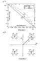
- FIG. 1 is a graph 100 plotting the achievable rates in a broadcast channel for a first and second user for three different transmission strategies.
- Vertical axis 102 represents the rate for the stronger receiver, while horizontal axis 104 represents the rate for the weaker receiver.
- Line 106 shows achievable rates for a time division multiplexing (TDM) strategy.
- Line 108 shows achievable rates for a frequency division multiplexing (FDM) strategy.
- Line 110 shows maximum capacity achievable rates.
- the transmitter allocates a certain fraction of the bandwidth, ⁇ , and a fraction of the available power, ⁇ , to the first user.
- the second user gets the remaining fractions of bandwidth and power. Having allocated these fractions, the transmitter communicates with the two receivers simultaneously.
- the rate region can be characterized by the following equations. R 1 ⁇ ⁇ W ⁇ log ⁇ 1 + ⁇ P N 1 , R 2 ⁇ 1 - ⁇ ⁇ W ⁇ log ⁇ 1 + 1 - ⁇ ⁇ P N 2 .
- the supremum of the rate regions achievable under all transmission strategies is the broadcast capacity region.
- this region is characterized by the equations R 1 ⁇ W ⁇ log ⁇ 1 + ⁇ P N 1 , R 2 ⁇ W ⁇ log ⁇ 1 + 1 - ⁇ ⁇ P ⁇ P + N 2 , and is indicated by the dash/dot curve line 110 corresponding to 'CAPACITY' as shown in Figure 1 .
- Figure 2 is a graph 200 illustrating a high power QPSK signal and a low power QPSK signal superposed on the high power QPSK signal.
- Vertical axis 202 represents Q-component signal strength while horizontal axis 204 represents P-component signal strength.
- the example of Figure 2 assumes QPSK modulation, the choice of modulation sets is not restrictive, and, in general, other modulation sets may be alternatively used.
- the example Figure 2 is sketched out for an exemplary case of two users, while the concept may be generalized and applied in a straightforward manner to multiple users. Assume that the transmitter has a total transmit power budget P.
- the first receiver referred to as 'weaker receiver'
- the second receiver referred to as 'stronger receiver'
- Four circles 206 filled in with a pattern, represent the QPSK constellation points to be transmitted at high power (better protected), (1- ⁇ )P, to the weaker receiver.
- additional information is conveyed to the stronger receiver at low power (less protected), ⁇ P , also using a QPSK constellation.
- arrow 208 of magnitude ⁇ ((1- ⁇ ) P ) provides an indication of the high transmission power
- arrow 210 ⁇ ( ⁇ P ) provides an indication of the low transmission power.
- the actually transmitted symbols which combine both the high power and low power signals, are represented as blank circles 212 in the figure.
- a key concept that this illustration conveys is that the transmitter communicates to both users simultaneously using the same transmission resource.
- the receiver strategy is straightforward.
- the weaker receiver sees the high power QPSK constellation with a low-power signal superposed on it.
- the SNR experienced by the weaker receiver may be insufficient to resolve the low-power signal, so the low power signal appears as noise and slightly degrades the SNR when the weaker receiver decodes the high power signal.
- the SNR experienced by the stronger receiver is sufficient to resolve both the high power and low power QPSK constellation points.
- the stronger receiver's strategy is to decode the high-power points (which are intended for the weaker receiver) first, remove their contribution from the composite signal, and then decode the low-power signal.
- New implementations using superposition coding methods may need methods to convey information between transmitters(s) and receiver(s) concerning the superposition coding, e.g., such as the temporary weaker/stronger assignment information.
- Methods of communicating such information that minimize overhead, where possible, and/or combine or link temporary assignment designations between multiple communication channel segments, e.g., an assignment channel segment and a traffic channel segment, would be advantageous.
- DE 2330263 A1 discloses a communications method for use in a communications system including a base station and a plurality of wireless terminals with different communication claimed existing between each wireless terminal in that plurality of wireless terminals and base station.
- a communication method for use in a communications system as set forth in claims 1 and 17, respectively, a base station for use in a communications system, as set forth in claim 11, and a wireless terminal, as set forth in claim 22, are provided.
- Preferred embodiments of the invention are described in the dependent claims.
- the present invention is directed to new and novel methods of using superposition coding in a communications systems, e.g., a multi-user communications system.
- Superposition coding occurs in a downlink and/or an uplink.
- Superposition coding in accordance with the invention occurs in the case of the downlink by transmissions to different wireless terminals from a base station using the same communications resource, e.g., simultaneously with the same frequencies.
- Superposition coding in accordance with the invention occurs in the case of the uplink by transmissions from different wireless terminals to a base station using the same communications resource.
- the signals combine in the communications channel resulting in one transmission being superimposed on the other transmission.
- the device e.g., base station
- receiving the superimposed signals uses superposition decoding techniques to recover both signals.
- assignments of channel segments to multiple wireless terminals is controlled by the base station.
- the transmission power levels are controlled by the base station so that the received power levels are very different to facilitate superposition decoding.
- the transmission power levels are controlled by the wireless terminals sharing the same uplink communications resource, e.g., time slot and frequency, to make sure that the received signals from the different devices at the base station will have different received power levels facilitating superposition decoding.
- the base station maintains information regarding the quality of the communications channels between individual wireless terminals and the base station.
- a communications channel segment is assigned to two or more wireless terminals having at least a minimum difference, e.g., a 3, 5 or 10 dB difference, in the quality of their communications channels from the base station in the downlink case or communications channels to the base station in the uplink case.
- Channel assignments are transmitted to wireless terminals which are to share a traffic channel segment. The assignment conveys which wireless terminals are to simultaneously use a communications channel segment and, in addition, which of the assigned devices is to transmit (in the uplink case) or receive (in the downlink case) the strong or weak signal. Assignment messages may be transmitted as superimposed signals.
- this document assumes that two signals are superimposed to form a superposition coding signal. However, more than two signals can be superimposed. The invention is applicable to cases where more than two signals are superimposed to form a superposition coding signal.
- the two signals of a superposition coding signal are respectively called the strong signal and the weak signal, where the strong signal is the one with high received power and the weak signal is the one with low received power.
- the strong signal is the one with high received power
- the weak signal is the one with low received power.
- the weaker user is the one with worse channel condition.
- a given wireless terminal may be the strong user when it shares the resource with another wireless terminal, and be the weaker user when it shares the resource with a third wireless terminal.
- the stronger user will be assigned to operate transmitting the signal which will be received by the base station as the strong signal and the weaker user will normally be assigned to operate transmitting the signal which will be received by the,base station as the weak signal. This avoids generating excessive interference to other base stations or requiring excessive peak transmission power from the wireless terminal.
- the stronger user is also called stronger transmitter and the weaker user is also called weaker transmitter.
- the stronger user will be assigned to operate receiving the weak signal and the weaker user will normally be assigned to operate receiving the strong signal. This helps to improve the link reliability of the weaker user while not wasting power to the stronger user.
- the stronger user is also called stronger receiver and the weaker user is also called weaker receiver.
- Channel assignments transmitted to wireless terminals which are to share a traffic channel segment may also be made using superposition coding.
- channel assignments are generally made by the base station and transmitted in the downlink.
- the assignment sent to the stronger user is transmitted with the weak signal and the assignment sent to the weaker user is transmitted with the strong signal.
- the wireless terminal knows that it is considered by the base station as the weaker user, i.e., the weaker transmitter in the case where the wireless terminal is assigned an uplink traffic channel or the weaker receiver in the case where the wireless terminal is assigned a downlink traffic channel.
- the wireless terminal knows that it is considered by the base station as the stronger user, i.e., the stronger transmitter where the wireless terminal is assigned an uplink traffic channel or the stronger receiver where the wireless terminal is assigned a downlink traffic channel.
- superposition coding can be used in an opportunistic manner. That is, superposition coding may be used when wireless terminals with sufficiently different channel conditions are available to be paired to share a communications channel segment. In cases where a sufficient difference in received power levels may not be achieved, e.g., due to an insufficient different in channel conditions between devices or insufficient transmission power capabilities, wireless terminals are not scheduled to share a transmission segment. Thus, superposition is used in transmission slots where it is likely to produce reliable results due to sufficient received power level differences but not in cases here it is likely to be unreliable.
- the present invention is directed to new and novel methods of using superposition coding in a communications systems, e.g., a multi-user communications system.
- Superposition coding occurs in a downlink and/or an uplink.
- Superposition coding in accordance with the invention occurs in the case of the downlink by transmissions to different wireless terminals from a base station using the same communications resource, e.g., simultaneously with the same frequencies.
- Superposition coding in accordance with the invention occurs in the case of the uplink by transmissions from different wireless terminals to a base station using the same communications resource.
- the signals combine in the communications channel resulting in one transmission being superimposed on the other transmission.
- the device e.g., base station
- receiving the superimposed signals uses superposition decoding techniques to recover both signals.
- assignments of channel segments to multiple wireless terminals is controlled by the base station.
- the transmission power levels are controlled by the base station so that the received power levels are very different to facilitate superposition decoding.
- the transmission power levels are controlled by the wireless terminals sharing the same uplink communications resource, e.g., time slot, to make sure that the received signals from the different devices at the base station will have different received power levels facilitating superposition decoding.
- FIG. 3 illustrates an exemplary wireless communications system 300 implemented in accordance with and using the methods of the present invention.
- Exemplary wireless communications system 300 opportunistically uses controlled superposition coding methods on uplink channels and downlink channels in accordance with the present invention.
- Exemplary wireless communications system 300 is a spread spectrum OFDM (orthogonal frequency division multiplexing) multiple-access system. While an exemplary OFDM wireless communications system is used in this application for purposes of explaining the invention, the invention is broader in scope than the example, and the invention can be applied in many other communication systems, e.g. a CDMA wireless communications system, as well where controlled superposition coding is employed.
- System 300 includes a plurality of cells: cell 1 302, cell M 304.
- Each cell includes a base station (BS), (BS 1 306, BS M 308), respectively, and represents the wireless coverage area of the base station.
- BS 1 306 is coupled to a plurality of end nodes, (EN(1) 310, EN(X) 312) via wireless links (314, 316), respectively.
- BS M 308 is coupled to a plurality of end nodes, (EN(1') 318, EN(X') 320) via wireless links (322, 324), respectively.
- the end nodes 310, 312, 318, 320 may be mobile and/or stationary wireless communications devices and are referred to as wireless terminals (WTs).
- WTs wireless terminals
- MNs Mobile WTs are sometimes referred to as mobile nodes (MNs). MNs may move throughout system 300.
- BS 1 306 and BS M 308 are coupled to network node 326 via network links 328, 330, respectively.
- Network node 326 is coupled to other network nodes and the Internet via network link 332.
- Network links 328, 330, 332 may be, e.g., fiber optic cables.
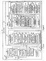
- FIG 4 is an illustration of an exemplary base station 400 implemented in accordance with the invention.
- Exemplary base station 400 may be a more detailed representation of any of the base stations 306, 308 of Figure 3 .
- Base station 400 includes a receiver 402, a transmitter 406, a processor 410, an I/O interface 412, and a memory 414 coupled together via bus 416 over which the various elements may interchange data and information.
- the receiver 402 is coupled to an antenna 404 through which base station 400 may receive uplink signals from a plurality of wireless terminals (WTs) 500 (See Figure 5 ).
- WTs wireless terminals
- Such uplink signals may include uplink traffic signals transmitted by different wireless terminals 500 on the same traffic segment which may superpose in the air and/or acknowledgment signals transmitted by different wireless terminals on the same acknowledgement segment which may superpose in the air, in accordance with the invention.
- Receiver 402 includes a plurality of demodulation modules, demodulation module 1418, demodulation module N 420.
- the demodulation modules 418, 420 may be part of a decoder module.
- the demodulation modules 418, 420 are coupled together.
- Demodulation module 1 418 may perform a first demodulation on a received superposed signal recovering a high power or highly protected signal. The demodulated information may be forwarded from demodulation module 1 418 to demodulation module N 420. Demodulation module N 420 may remove the high power or highly protected signal from the received superposed signal, and then demodulate the low power or less protected signal.
- separate receivers 402 and/or separate antennas 404 may be used, e.g., a first receiver for the high (received) power or highly protected uplink signals and a second receiver for the low (received) power or low protection uplink signals.
- Transmitter 406 is coupled to an antenna 408 through which base station 400 may transmit downlink signals to a plurality of wireless terminals 500.
- Such downlink signals may include superposed signals, e.g., a composite of two or more signals on the same channel segment, each signal of the composite at a different transmission power level, and each signal intended for a different wireless terminal.
- Superposed downlink signals may be opportunistically transmitted on assignment segments, on downlink traffic signals, and/or on acknowledgment segments, in accordance with the invention.
- Transmitter 406 includes a plurality of modulation modules, modulation module 1 422, modulation module N 424, and a superposition module 426.
- Modulation module 1 422 may modulate a first set of information, e.g., into a high power or highly protected signal, and modulation module N 424 may modulate a second set of information into a low power or low protection signal.
- Superposition module 426 combines the high power or highly protected signal with the low power or low protection signal such that a composite signal may be generated and transmitted on the same downlink segment.
- multiple transmitters 406 and/or multiple antennas 408 may be used, e.g., a first transmitter for the high powered or highly protected downlink signals and a second transmitter for the low powered or low protection downlink signals.
- I/O interface 412 is an interface providing connectivity of the base station 400 to other network nodes, e.g., other base stations, AAA server nodes, etc., and to the Internet.
- Memory 414 includes routines 428 and data/information 430.
- Processor 410 e.g., a CPU, executes the routines 428 and uses the data/information 430 in memory 414 to operate the base station 400 in accordance with the methods of the present invention.
- Routines 428 include communications routines 432 and base station control routines 434.
- Base station control routines 434 include a scheduler module 436, wireless terminal power control routines 438, transmit power control routines 440, and signaling routines 442.
- Scheduler 436 includes a downlink scheduling module 446, an uplink scheduling module 448, and a relative user strength matching module 450.
- WT transmit power control routine 438 includes a received power target module 452.
- Data/Information 430 includes data 454, wireless terminal data/information 456, system information 458, downlink assignment messages 460, downlink traffic channel messages 462, received acknowledgement messages 464, uplink assignment messages 466, uplink traffic channel messages 468, and acknowledgement messages for uplink traffic 470.
- Data 454 includes user data, e.g., data received from WTs over wireless links, data received from other network nodes, data to be transmitted to WTs, and data to be transmitted to other network nodes.
- Wireless terminal data/information 456 includes a plurality of WTs information, WT 1 information 472, WT N information 474.
- WT 1 information 472 includes data 476, terminal identification (ID) information 478, received channel quality report information 480, segment information 482, and mode information 483.
- Data 476 includes user data received by BS 400 from WT 1 intended for a peer node of WT 1, e.g., WT N, and user data intended to be transmitted from BS 400 to WT1.
- Terminal ID information 478 includes a base station assigned ID used to identify WT1 in communications and operations with BS 400.
- Received channel quality report information 480 includes downlink channel quality feedback information such as, e.g., SNR (signal-to-noise-ratio), SIR (signal-to-interference-ratio).
- Mode information 483 includes information indicating the current mode of WT1, e.g., on state, sleep state, etc.
- Segment information 482 includes a plurality of segment information sets corresponding to channel segments assigned to WT1, segment 1 information 484, segment N information 486.
- Segment 1 information 484 includes segment type information 488, segment ID information 490, coding information 492, and relative strength designation information 494.
- Segment type information 488 includes information identifying the segment's type, e.g., assignment segment for uplink traffic, assignment segment for downlink traffic, uplink traffic channel segment, downlink traffic channel segment, acknowledgment channel segment corresponding to an uplink traffic channel segment, acknowledgement segment corresponding to a downlink traffic channel segment.
- Segment identification (ID) information 490 includes information used in identifying the segment, e.g., information used in identifying the frequencies, time, duration, and/or size associated with the segment.
- Coding information 492 includes information identifying the type of coding and/or modulation used for the segment.
- Relative strength designation information 494 includes information indicating the designated WT relative strength for the purposes of communication on this segment. In some embodiments, the relative strength designation information 494 includes information identifying the WT as either a weak or strong WT for the purposes of communications on this segment.
- System information 458 includes tone information 495, modulation information 496, timing information 497, transmission power model information 498, and received power target model information 499.
- Tone information 495 includes information identifying tones used in hopping sequences, channels, and/or segments.
- Modulation information 496 includes information used by BS 400 to implement the various modulation and/or coding schemes, e.g., coding rate information, modulation type information, error correction code information, etc.
- Timing information 497 may include timing information used for hopping sequences, superslots, dwells, durations of channel segments, and timing relationships between different types of channel segments, e.g., a timing relationship between an assignment segment, a traffic channel segment, and an acknowledgment channel segment.
- Transmission power model information 498 may include information defining models distinguishing transmission power levels of a strong signal and a transmission power level of a weak signal, wherein the two signals are transmitted on the same channel segment as a combined superposed signal, in accordance with the invention.
- Received power model target information 499 may include information such as look-up tables used to define models for controlling the WT transmit power to transmit at an appropriate power level in order to achieve a received power target at BS 400 for an uplink channel segment signal.
- a received power model target for a wireless terminal is a function of coding rate and classification of the user (wireless terminal) as a strong or weak user (wireless terminal).
- the received power targets may be very different between the strong and weak classification, e.g., a value > 3 dB such as 10 dB .
- Downlink assignment messages 460 include assignment messages used to notify a WT terminal that it has been assigned a downlink traffic channel segment. Downlink assignment messages 460 are transmitted by BS 400 to WTs on downlink assignment channel segments. In accordance with the invention, multiple downlink assignment messages may be transmitted to multiple WTs on the same assignment segment using controlled superposition coding. Downlink traffic messages 462 include data and information, e.g., user data, transmitted from BS 400 to WTs on downlink traffic channel segments. In accordance with the invention, downlink traffic channel messages 462 may be transmitted to multiple WTs on the same assignment segment using controlled superposition coding.
- Received acknowledgement messages 464 include acknowledgement signals from WTs to BS 400 indicating whether or not a WT has successfully received data/information on an assigned downlink traffic channel segment.
- acknowledgement messages 464 may have been transmitted by multiple WTs, e.g., with very different received power target levels, to BS 400 on the same assignment segment and the signals may have superposed in the air link.
- Uplink assignment messages 466 include assignment messages used to notify a WT terminal that it has been assigned an uplink traffic segment. Uplink assignment messages 466 are transmitted by BS 400 to WTs on downlink assignment channel segments used for assigning uplink channel segments. In accordance with the invention, multiple uplink assignment messages may be transmitted to multiple WTs on the same assignment segment using controlled superposition coding. Uplink traffic channel messages 468 include data and information, e.g., user data, transmitted from WTs to BS 400 on uplink traffic channel segments. In accordance with the invention, uplink traffic channel messages 468 may be transmitted by multiple WTs, e.g., with very different received power target levels, to BS 400 on the same assignment segment and the signals may superpose over the air link.
- Acknowledgement messages for uplink traffic 470 include acknowledgement signals to be transmitted from BS 400 to WTs indicating whether or not BS 400 has successfully received data/information on an assigned uplink traffic channel segment.
- multiple acknowledgement messages for uplink traffic 470 may be transmitted to multiple WTs on the same acknowledgement segment using controlled superposition coding.
- Communications routines 432 is used for controlling base station 400 to perform various communications operations and implement various communications protocols.
- Base station control routine 434 is used to control the base station 400 operations, e.g., I/O interface control, receiver 402 control, transmitter 406 control, and to implement the steps of the method of the present invention.
- the scheduler module 436 is used to control transmission scheduling and/or communication resource allocation.
- the scheduler module 436 may serve as a scheduler.
- the downlink scheduling module 446 schedules WTs to downlink channel segments, e.g., downlink traffic channel segments.
- Downlink scheduling module 446 may opportunistically schedule multiple WTs to the same downlink segment, e.g., the same downlink traffic channel segment.
- the uplink scheduling module 448 schedules WTs to uplink channel segments, e.g., uplink traffic channel segments.
- the uplink scheduling module 448 may opportunistically schedule multiple WTs to the same uplink segment, e.g., the same uplink traffic channel segment.
- the opportunistic scheduling and classification of multiple users as weaker/stronger on some corresponding downlink and uplink segments may be interrelated and follow predetermined methods known to both base station 400 and WTs 500.
- Relative user strength matching module 450 may use the received channel quality report information 480 from multiple WTs to classify users with respect to each other on a relative basis as weaker/stronger and to match users, e.g., one relative weaker with one relative stronger, for concurrent scheduling on a given channel segment.
- the relative strength matching routine 450 may use other criteria in addition to or in place of the channel quality report information 480 to determine WT matching. For example, some WTs in the population of wireless terminals, e.g., low cost devices, may not have the appropriate demodulation and/or decoding capability to decode a weak signal superposed with a strong signal, and thus should not be scheduled as a strong receiver. Other WTs in the population, e.g., stationary wireless devices with less stringent size and power constraints, may be good candidates for decoding weak signals superposed on strong signals, and thus can be a good choice for scheduling as a strong receiver.
- WT power control routine 438 controls the transmission power levels of the WTs operating within BS 400's cell.
- Received power target module 452 uses the data/information 430 including the received power target model information 499, the coding information 492, and the relative strength designation information 494 to determine a received power target for uplink signals on uplink segments.
- Transmit power control routine 440 uses the data/information 430 including the transmission power model information 498, coding info 492, and relative strength designation information 494 to control the transmitter 406 to transmit downlink signals at the appropriate assigned strength for the given segment.
- Signaling routines 442 may be used by receiver 402, transmitter 406, and I/O interface 412 to control the generation, modulation, coding ,transmission, reception, demodulation, and/or decoding of communicated signals.
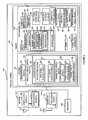
- FIG. 5 is an illustration of an exemplary wireless terminal 500 implemented in accordance with the invention.
- Exemplary wireless terminal 500 may be a more detailed representation of any of end nodes 310, 312, 318, 320 of Figure 3 .
- Wireless terminal 500 may be a stationary or mobile wireless terminal. Mobile wireless terminals are sometimes referred to as mobile nodes and may move throughout the system.
- Wireless terminal 500 includes a receiver 502, a transmitter 504, a processor 506, and a memory 508 coupled together via bus 510 over which the various elements may interchange data and information.
- the receiver 502 is coupled to an antenna 511 through which wireless terminal 500 may receive downlink signals from a base station 400.
- downlink signals may include controlled superposed assignments signals, controlled superposed downlink traffic signals, and/or controlled superposed acknowledgement signals transmitted by base station 400 in accordance with the invention.
- Receiver 502 includes a plurality of demodulation modules, demodulation module 1 512, demodulation module N 514.
- the demodulation modules 512, 514 may be part of a decoder module(s).
- the demodulation modules 512, 514 are coupled together.
- Demodulation module 1 512 may perform a first demodulation on a received superposed signal recovering a high power or highly protected signal.
- the demodulated information may be forwarded from demodulation module 1512 to demodulation module N 514.
- Demodulation module N 514 may remove the high power or highly protected signal from the received superposed signal, and then demodulate the low power or less protected signal.
- separate receivers 502 and/or separate antennas 511 may be used, e.g., a first receiver for the high power or highly protected downlink signal recovery and a second receiver for the low power or low protection downlink signal recovery.
- Transmitter 504 is coupled to an antenna 515 through which wireless terminal 500 may transmit uplink signals to a base station 400. Such uplink signals may include uplink traffic channel signals and acknowledgements signals. Transmitter 505 includes a modulation module 516. Modulation module 506 may modulate data/information into uplink signals. In some embodiments, the modulation module 506 may be part of an encoder module. The transmitter 504 may be controlled in terms of output power and/or modulation to output uplink signals with different levels of target received power and/or different relative levels of protection, e.g., high targeted received power signals (or highly protected signals) and low targeted received power signals (or less protected signals) for different uplink channel segments in accordance with the invention.
- high targeted received power signals or highly protected signals
- low targeted received power signals or less protected signals
- Memory 508 includes routines 518 and data/information 520.
- Routines 518 include communications routine 522 and wireless terminal control routines 524.
- Wireless terminal control routines 524 include signaling routines 526 and channel quality measurement module 528.
- Signaling routines 526 include a receiver control module 530 and a transmitter control module 532.
- Receiver control module 530 includes a plurality of signal detection modules, first signal detection module 534, Nth signal detection module 536.
- Transmitter control module 532 includes a signal generation module 538 and a transmitter power control module 539.
- Data/Information 520 includes data 540, terminal identification (ID) information 542, segment information 544, mode information 546, channel quality information 548, tone information 550, modulation information 552, timing information 554, transmission power model information 556, received power target model information, received downlink assignment messages 560, received downlink traffic channel messages 562, acknowledgement messages for downlink traffic 564, uplink assignment messages 566, uplink traffic channel messages 568, and received acknowledgement messages for uplink traffic 570.
- ID terminal identification
- Data 540 includes user data, e.g., data from a communication peer of WT 500 routed through BS 400 and received in downlink signals from BS 400. Data 540 also includes user data to be transmitted in uplink signals to BS 400 intended for peer nodes of WT 500, e.g., another WT in a communications session with WT 500.
- Terminal ID information 542 includes a base station assigned ID used to identify WT 500 in communications and operations with BS 400.
- Segment information 544 includes a plurality of communication channel segment information sets corresponding to channel segments assigned to WT 500, segment 1 information 574, segment N information 576.
- Segment 1 information 574 includes segment type information 578, segment identification (ID) information 580, coding information 582, and relative strength designation information 584.
- Segment 1 information 574 includes segment type information 578, segment ID information 580, coding information 582, and relative strength designation information 584.
- Segment type information 578 includes information identifying the segment's type, e.g., assignment segment for uplink traffic, assignment segment for downlink traffic, uplink traffic channel segment, downlink traffic channel segment, acknowledgment channel segment corresponding to an uplink traffic channel segment, acknowledgement segment corresponding to a downlink traffic channel segment.
- Segment identification information 580 may include information used in identifying the segment, e.g., information used in identifying the frequencies, time, duration and/or size associated with the segment.
- Coding information 582 includes information identifying the type of coding and/or modulation used for the segment.
- Relative strength designation information 584 includes information indicating the designated WT relative strength for the purposes of communication on this segment. In some embodiments, the relative strength designation information 584 includes information identifying the WT as either a weak or strong WT for the purposes of communications on this segment.
- Channel quality report information 548 includes downlink channel quality information such as, e.g., SNR (signal-to-noise-ratio), SIR (signal-to-interference-ratio).
- Channel quality report information 548 may be obtained from measurements of downlink signals received from BS 400, e.g., measurements of pilot signals and/or beacon signals.
- Channel quality report information 548 is fed back to BS 400 and is used by the BS 400 in making decisions regarding opportunistically matching and scheduling users as relative weaker/stronger WTs on the same segment, in accordance with the invention.
- Mode information 546 includes information indicating the current mode of WT1, e.g., on state, sleep state, etc.
- Tone information 550 includes information identifying tones used in hopping sequences, channels, and/or segments.
- Modulation information 552 includes information used by WT 500 to implement the various modulation and/or coding schemes, e.g., coding rate information, modulation type information, error correction code information, etc.
- Timing information 554 may include timing information used for hopping sequences, superslots, dwells, durations of channel segments, and timing relationships between different types of channel segments, e.g., a timing relationship between an assignment segment, a corresponding traffic channel segment, and a corresponding acknowledgment channel segment.
- Received power model target information 558 may include information such as look-up tables used to define models for controlling the WT transmit power to transmit at an appropriate power level in order to achieve a received power target at BS 400 for an uplink channel segment signal.
- a received power model target for wireless terminal 500 is a function of coding rate and classification of the user (wireless terminal) as a strong or weak user (wireless terminal).
- the received power targets may be very different between the strong and weak classification, e.g., a value > 3 dB such as 10 dB.
- Received downlink assignment messages 560 include received assignment messages from BS 400 used to notify WT terminal 500 that it has been assigned a downlink traffic segment. Downlink assignment messages are transmitted by BS 400 to WT 500 on downlink assignment channel segments. In accordance with the invention, a received downlink assignment message 560 may be one of multiple downlink assignment messages transmitted to multiple WTs on the same assignment segment using controlled superposition coding. Received downlink traffic messages 562 include data and information, e.g., user data, transmitted from BS 400 to WTs on downlink traffic channel segments. In accordance with the invention, a received downlink traffic channel message 562 may be one multiple downlink traffic messages transmitted to multiple WTs on the same assignment segment using controlled superposition coding.
- Acknowledgement messages for downlink traffic 564 include acknowledgement messages to be transmitted by WT 500 to BS 400 indicating whether or not WT 500 has successfully received data/information on an assigned downlink traffic channel segment.
- acknowledgement messages 564 may be transmitted, with a controlled received power target, by WT 500 to BS 400 on the same assignment segment used by other WTs.
- Received uplink assignment messages 566 include assignment messages used to notify WT 500 that it has been assigned an uplink traffic segment. Received uplink assignment messages 566 are obtained from received signals of BS 400 transmissions to WT 500 on downlink channel segments used for assigning uplink channel segments. In accordance with the invention, a received uplink assignment message 566 may be one of multiple uplink assignment messages transmitted by BS 400 to multiple WTs on the same assignment segment as part of a controlled superposed signal in accordance with the invention.
- Uplink traffic channel messages 568 include data and information, e.g., user data, transmitted from WT 500 to BS 400 on uplink traffic channel segments.
- uplink traffic channel messages 568 may be transmitted, with a controlled received power target, by WT 500 to BS 400 on the same assignment segment as other WTs are transmitting uplink traffic channel messages and the signals from multiple WTs may superpose over the air link.
- Acknowledgement messages for uplink traffic 570 include acknowledgement signals from BS 400 to WTs indicating whether or not BS 400 has successfully received data/information on an assigned uplink traffic channel segment.
- base station 400 may transmit multiple acknowledgement messages to multiple WTs in a combined controlled superposed signal on the acknowledgment segment.
- Communications routine 522 is used for controlling wireless terminal 500 to perform various communications operations and implement various communications protocols.
- Wireless terminal control routines 524 is used to control the wireless terminal 500 operations, e.g., receiver 502 control, transmitter 504 control, and to implement the steps of the method of the present invention.
- Signaling routines 526 include a receiver control module 530 used for control related to downlink signaling and a transmitter control module 532 used for control related to uplink signaling.
- Receiver control module 530 directs the operation of receiver 502 to receiver, demodulate, and/or decode downlink signals from base station 400 including superposed signals.
- First signal detection module 534 uses the data/information 520 including modulation information 552 and segment information 544 to control demodulation module 1 512 to receive and process signals, e.g., recovering a high power or high protection signal from a superposed downlink signal.
- Nth. signal detection module 536 uses the data/information 520 including modulation information 552 and segment information 544 to receive and process signals, e.g., recovering a low power or low protection signal from a superposed downlink signal.
- Transmitter control module 532 directs the operation of transmitter 504 and its modulation module 516 for operations related to uplink signaling such as signal generation and power control.
- Signal generation module 538 uses data/information 520 including modulation information 552 and ⁇ segment information 544 to generate uplink signals from uplink information to be communicated, such as, e.g., uplink traffic channel messages 568.
- Transmitter power control module 539 uses data/information 520 including received power target model information 558 and segment information 544 such as coding information 582 and relative strength designation information 584 to control the transmitter to regulate the uplink signal strength for uplink segments, e.g., individual uplink segments.
- the transmitter power control module 539 may adjust transmission power levels for individual segments to attempt to reach a received power target level at the base station 400, in accordance with the invention.
- This control of wireless terminal transmission power with respect to expected received power at a base station allows for the base station 400 to opportunistically schedule multiple wireless terminals on the same uplink segment with different received power targets, to receive an uplink signal including superposed signals from multiple wireless terminals, and to extract the individual signals from each wireless terminal.
- Channel quality measurement module 528 performs measurements of received signals, e.g., pilot signals and/or beacon signals, to obtain channel quality information 548.
- the air link resource generally includes bandwidth, time and/or code.
- the air link resource that transports data and/or voice traffic is called the traffic channel.
- Data is communicated over the traffic channel in traffic channel segments (traffic segments for short). Traffic segments may serve as the basic or minimum units of the available traffic channel resources.
- Traffic segments may serve as the basic or minimum units of the available traffic channel resources.
- Downlink traffic segments transport data traffic from the base station to the wireless terminals, while uplink traffic segments transport data traffic from the wireless terminals to the base station.
- One exemplary system in which the present invention is used is the spread spectrum OFDM (orthogonal frequency division multiplexing) multiple-access system in which a traffic segment includes of a number of frequency tones over a finite time interval.
- the traffic segments are dynamically shared among the wireless terminals that are communicating with the base station.
- a scheduling function e.g., module in the base station may assign each uplink and downlink segment to one or more of the wireless terminals, e.g., mobile terminals, based on a number of criteria.
- FIG. 6 is a diagram 600 of frequency on vertical axis 602 vs time on horizontal axis 604 and illustrates exemplary traffic segments.
- Traffic segment A 606 is indicated by the rectangle with vertical line shading
- traffic segment B 608 is indicated by the rectangle with horizontal line shading.
- traffic segments A 606 and B 608 occupy the same frequencies but occupy different time intervals.
- segment A 606 is assigned to user #1 by the base station's scheduler and segment B 608 is assigned to user #2.
- the base station's scheduler can rapidly assign the traffic channel segments to different users according to their traffic needs and channel conditions, which may be time varying in general. The traffic channel is thus effectively shared and dynamically allocated among different users on a segment-by-segment basis.
- the assignment information of traffic channel segments is transported in the assignment channel, which includes a series of assignment segments.
- assignment segments are generally transmitted in the downlink.
- Each traffic segment may be, and generally is, associated with a unique assignment segment.
- the associated assignment segment conveys the assignment information of the corresponding traffic segment.
- the assignment information may include the identifier of the user terminal(s), which is assigned to utilize that traffic segment, the coding and/or modulation scheme to be used in that traffic segment.
- Figure 7 is a diagram 700 illustrating exemplary assignment and traffic segments.
- Figure 7 shows frequency on vertical axis 702 vs time on horizontal axis 704.
- Figure 7 includes two assignment segments, A' 706 and B' 708, and two traffic segments, traffic segment A 710 and traffic segment B 712.
- the exemplary assignment segments 706, 708 occupy the same frequencies but occupy different time intervals.
- the exemplary traffic segments 710, 712 occupy the same frequencies but occupy different time intervals.
- the assignments segments 706, 708 occupy different frequencies than the traffic segments 710, 712.
- Assignment segment A' 706 conveys the assignment information of traffic segment A 710 as indicated by arrow 714.
- Assignment segment B' 710 conveys the assignment information for traffic segment B 712 as indicated by arrow 716.
- Each assignment segment 706, 708 precedes its respective traffic segment 710, 712.
- the assignment channel is a shared channel resource. The users receive the assignment information conveyed in the assignment channel and then utilize the traffic channel segments according to the assignment information.
- Data transmitted by the base station on a downlink traffic segment is decoded by a receiver in the intended wireless terminal while data transmitted by the assigned wireless terminal on the uplink segment is decoded by a receiver in the base station.
- the transmitted segment includes redundant bits that help the receiver determine if the data is decoded correctly. This is done because the wireless channel may be unreliable and data traffic, to be useful, typically has high integrity requirements.
- the transmission of a traffic segment may succeed or fail.
- the receiver of a traffic segment sends an acknowledgment to indicate whether the segment has been received correctly.
- the acknowledgment information corresponding to traffic channel segments is transported in the acknowledgment channel, which includes a series of acknowledgment segments.
- Each traffic segment is associated with a unique acknowledgment segment.
- the acknowledgment segment is in the uplink.
- the acknowledgment segment is in the downlink.
- the acknowledgment segment can convey one-bit of information, e.g., a bit, indicating whether the associated traffic segment has been received correctly or not.
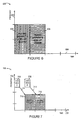
- FIG. 8 includes a diagram 800 showing exemplary downlink traffic channel segments and a graph 850 showing exemplary uplink acknowledgement segments.
- Diagram 800 plots frequency on vertical axis 802 vs time on horizontal axis 804.
- Diagram 800 includes downlink traffic segment A 806 illustrated by vertical line shading and downlink traffic segment B illustrated by horizontal line shading. Each traffic segment 806, 808 occupies the same frequencies but a different time slot.
- Graph 850 plots frequency on vertical axis 852 vs time on horizontal axis 854.
- Graph 850 includes uplink acknowledgement segment A" 856 and uplink acknowledgement segment B" 858. Each acknowledgement segment 856, 858 occupies the same frequencies but a different time slot.
- the two uplink acknowledgment segments, A" 856 and B" 858 convey the acknowledgment information of downlink traffic segments A 806 and B808, respectively.
- the linkage between traffic segments A 806 to acknowledgement segment A" 856 is indicated by arrow 860; the linkage between traffic segment B 808 and acknowledgement segment B" 858 is indicated by arrow 862.
- This invention realizes the benefits of superposition coding in a multi-user communication system while using simple receiver design in both the broadcast channel and the multiple-access channel.
- the advantages of using superposition coding are greater in systems where there is a large dynamic range in the channel quality experienced by different users.
- wireless communication systems it is common to find the channel quality varying by as much as 30dB or even higher (three orders of magnitude) among various users.
- the advantages conferred by this invention contribute significantly to enhanced system capacity in such systems.
- Superposition coding in accordance with the present invention, in the context of the downlink (broadcast) channel shall now be described.
- the transmitter of this downlink (broadcast) channel is the base station and the receivers are mobile or fixed wireless user terminals, e.g., sometimes referred to as mobile users or users, served by the base station.
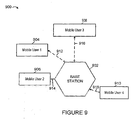
- An example of such a system is illustrated in exemplary system 900 of Figure 9 where a base station 902 is communicating on the downlink as well as the uplink with four mobile users, mobile user 1 904, mobile user 2 906, mobile user 3 908, mobile user 4 910 via wireless links 912, 914, 916, 918, respectively.
- the mobile users 904, 906, 908, 910 are at different distances from the base station 902 and consequently may experience different channel conditions.
- the users 904, 906, 908, 910 frequently update the base station 902 with a measure of the downlink channel quality and interference condition they currently experience.
- the base station 902 typically uses this information to schedule users for transmission and allocates the downlink channel resources to them.
- the base station 902 can use the channel quality and interference condition report to allocate transmission power to different users 904, 906, 908, 910 on the broadcast channel. Users, e.g.
- mobile user 2 906 and mobile user 4 910 who are closer to the base station 902 are generally allocated smaller amounts of power while users, e.g., mobile user 1 904 and mobile user 3 908, who are located farther away from the base station 902 are allocated large amounts of power.
- Bandwidth can be allocated appropriately to different users 904, 906, 908, 910 based on the channel conditions.
- the most commonly used metric of channel quality is the receive signal-to-noise ratio (SNR), while other similar or equivalent metrics can be used.
- SNR receive signal-to-noise ratio
- the base station scheduler can select two or more user terminals to be scheduled on the same traffic segment.
- the selected terminals should preferably have SNRs that span a wide dynamic range.
- Superposition coding is then used to send data to the selected terminals on the same traffic segment. It should be pointed out here that practically speaking, the advantages of using superposition coding may be realizable by scheduling two appropriately selected users on a given traffic segment although, in some embodiments, larger numbers of users may be scheduled. Scheduling a small number of users, e.g., two, has the advantage of resulting in a significantly less decoding effort at user terminals compared to the case when a larger number of users (>2) are scheduled on the same traffic segment.
- the base station is not always required to use superposition coding, but can do so in an opportunistic manner.
- the base station can default to the simple state where it transmits to a single user.
- the transmitter will consider 'B' to be a 'strong user' and 'C' a 'weak user' when transmitting to these two users together using superposition coding.
- user 'A' is considered the strong user, with user B being considered the weak user.
- the users can derive their current status from the control channel that transmits the assignment information about which users are currently scheduled with high or low power signals.
- the signal intended for the weaker users is protected more e.g., with better coding or higher power, than the signal intended for stronger users, which are protected less.
- the receiver of the uplink (multiple-access) channel is the base station and the transmitters are the user terminals served by the base station.
- the multiple-access channel is divided among the users in time or code space or frequency.
- the channel may be shared among multiple users, with their signals interfering with each other at the base station receiver.
- a CDMA system is an example of a system where the channel may be shared among multiple users.
- the user signals can be separated using joint detection (also known as multi-user detection) techniques. In practice, however, this is quite complex.
- the base station scheduler can select two or more user terminals to transmit uplink data on the same traffic segment resource.
- the signals from the selected terminals are superposed in the transmission medium.
- Figure 10 is a diagram 1000 used for illustrating superposition coding in a multiple-access channel in accordance with the present invention.
- Figure 10 shows different receive power targets of two superposed signals.
- Figure 10 includes an exemplary high power QPSK signal illustrated by the four shows shaded circles 1002 and an exemplary low power QPSK signal 1004 illustrated by the four unshaded circles.
- the strength of the high power signal may be represented by long arrow 1006 from the origin 1008 to a point 1002 with magnitude ⁇ (1- ⁇ ) P
- the strength of the low power signal may be represented by short arrow 1010 from the origin 1008 to a point 1004 with magnitude ⁇ P
- the base station scheduler can coordinate operations so that the selected user terminal uplink signals are received at different power levels.
- wireless terminals with smaller path loss may be operated so that their uplink signals are to be received by the base station at a relative higher power
- wireless terminals with larger path loss may be operated so that their uplink signals are to be received by the station at a relative lower power.
- the scheduler can select user terminals that span a large range of path losses for the same traffic segment.
- the user terminals that cause less out-of-cell interference may be operated so that their signals are to be received by the base station at relative higher power, while the user terminals that cause more out-of -cell interference may be operated so that their signals are to be received by the base station at relative lower power.
- the scheduler can select terminals that span a large range in the out-of-cell interference that they create for the same traffic segment.
- Users are not pre-assigned 'strong' and 'weak' labels.
- the labeling of users as 'stronger' or 'weak', in accordance with the invention, is in a relative context.
- a 'strong' user in this case refers to a user terminal that is operated to be received at a higher power compared with another 'weaker' user transmitting on the same traffic segment.
- a user can learn whether it should target a higher or lower receive power level, e.g., from a control channel, in which the base station may, and in various embodiments does, instruct the users about the assignment information of the traffic channel.
- the base station In the event that the base station is constrained, it can choose not to schedule more than one user terminal on one traffic segment. This choice is completely transparent to the users, which really do not need to do anything different whether superposition is used or not.
- the downlink traffic channel fits within the broadcast communications method regime, while the uplink traffic channel is a typical example of the multiple-access communications method.
- Both the downlink and uplink traffic segments are dynamically assigned to the users according to the scheduler decisions made by the base station scheduler.
- the base station scheduler also determines the coding and modulation rate used in the traffic segment.
- the assignment channel is the control channel that conveys the assignment information to the wireless terminals, e.g., mobile user terminals. This embodiment of the invention is described using two subsystems, one for the downlink broadcast channel, and the other for the uplink multiple-access channel.
- Each mobile user in the system frequently updates the base station of its downlink channel condition, e.g., in a channel quality and interference condition feedback report.
- This report may include various parameters such as signal-to-noise ratio, channel frequency profile, fading parameters, etc.
- the base station schedules two or more users and superposes user signals on each downlink traffic segment.
- the base station also selects parameters, such as code rates and transmission power, for the superposed signals.
- the scheduler decisions corresponding to a traffic segment are communicated on the corresponding assignment segment, which is monitored by the users, e.g., wireless terminals.
- the assignment information can also be superposition coded on the assignment segment.
- Figure 11 includes two exemplary receivers, a weaker receiver 1102 and a stronger receiver 1104.
- Figure 11 also includes an assignment segment 1106 and a traffic segment 1108.
- the base station transmits a composite assignment signal with superposition coding 1110 to both receivers 1102, 1104.
- the base station subsequently transmits a composite traffic signal with superposition coding 1112 to both receivers 1102, 1104.
- the assignment information for the weaker receiver 1102 is sent as high power signal of the superposition codes on the assignment channel, while the assignment information for the stronger receiver 1104 is sent as the low power signal of the superposition codes on the assignment channel.
- a user 1102, 1104 first decodes the high power signal component of an assignment segment 1106. If the user is assigned by the high power signal of the assignment segment 1106, as user 1102 is, then the user knows that it is scheduled as 'weaker receiver' and shall also decode the high power signal of the composite signal 1112 of the corresponding traffic channel segment 1108. Otherwise, the user shall proceed to decode the low power signal of the assignment segment 1106 since it may be considered the stronger receiver. Again, if the user is assigned by the low power signal of the assignment segment, as receiver 1104 is, then the user knows that it is scheduled as 'stronger receiver' and shall proceed to decode the low power signal of the corresponding traffic channel segment 1108.
- the user may not be in a position to decode the low power signal of the composite traffic signal 1112 of the traffic segment 1108 and can choose not to attempt to decode it.
- the high power signal can be a better protected signal
- the low power signal can be a less protected signal.
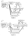
- Figure 12 is a drawing 1200 illustrating superposition coding used in broadcast assignment and multiple-access traffic channels.
- Figure 12 includes a key 1201 illustrating that solid heavy arrows denote downlink signals while heavy dashed arrows denote uplink signals.
- Figure 12 includes a base station receiver 1202, a first user, e.g. a wireless terminal, designated the weaker transmitter 1204, and a second user, e.g., a wireless terminal, designated the stronger transmitter 1206.
- Figure 12 also shows an assignment segment 1208.
- a downlink composite assignment signal 1210 including superposition coding, is transmitted from the base station to the two wireless terminals 1204, 1206 on the assignment segment 1208.
- Wireless terminal 1204 transmits signal 1214 including weaker user data 1212 to base station receiver 1202, while wireless terminal 1206 transmits signal 1216 including stronger user data 1218 to base station receiver 1202.
- Signals 1212 and 1216 are transmitted on the same uplink traffic segment and the signals are superposed over the air.
- the base station schedules one or more users 1204, 1206, who then superpose their signals 1212, 1216 on a single uplink traffic segment over the air.
- the base station can also select parameters, such as code rates and transmission power, for the superposed signals 1212, 1216.
- the base station makes the scheduling decision with a bias towards users who can be power controlled in a manner such that they are received at different powers at the base station.
- the users that are superposed can be users that in one embodiment, experience different path losses in the uplink or in another embodiment, users that have quite different uplink out-of-cell interference impact.
- the base station then communicates this decision using superposition coding on the assignment channel in downlink composite assignment signal 1210.
- a user e.g., a mobile wireless terminal, first decodes the high power (better protected) signal of an assignment segment 1208.
- the user if the user is assigned by the high power signal of the assignment segment 1208, then the user infers that it is scheduled by the base station as a 'weaker transmitter' and shall send on the corresponding uplink traffic segment to be received at lower power.
- user 1204 has inferred that it is scheduled by the base station as the weaker transmitter and transmits uplink traffic signal 1212 at a low targeted receive power level.
- the user if the user is in a position to decode the low power (less protected) signal included in composite signal 1212 on the assignment channel 1208, and finds that it is scheduled, it infers its current state to be a 'stronger transmitter'. It then proceeds to transmit on the corresponding uplink traffic segment with suitable transmit power such that it is received at higher power.
- user 1206 first decodes and removes the weaker user assignment, then decodes the stronger user assignment, finds that it is scheduled, infers that it is the stronger transmitter, and transmits uplink traffic signal 1216 at a high targeted receive power level.
- the user may not use the corresponding uplink traffic segment as a 'strong transmitter'.
- the notion of stronger and weaker transmitters may be defined based on other criteria such as uplink interference cost or device-related constraints.
- superposition coding can, and is, carried out in an opportunistic manner and need not be carried out on each of the traffic segments. This allows the base station scheduler significant flexibility.
- the low-power signal is sent on the assignment channel when users with divergent channel conditions are found, and the low-power signal is not sent on the assignment channel at other times. Otherwise, if both high and low power signals were transmitted on the same channel segment when divergent channel conditions did not exist, the users may be able to detect the high power signal on the assignment channel but may decode noise when they attempt to decode a potential superposed low-power signal.
- the receiver after a traffic segment is received, the receiver generally sends an acknowledgment, in the acknowledgment channel, to inform the transmitter whether the traffic segment has been correctly received.
- an acknowledgment in the acknowledgment channel, to inform the transmitter whether the traffic segment has been correctly received.
- there is a corresponding uplink acknowledgment segment for each downlink traffic segment, there is a corresponding uplink acknowledgment segment, and for each uplink traffic segment, there is a corresponding downlink acknowledgment segment.
- the uplink acknowledgment channel is implemented as a multiple-access channel using multiple access communication methods. From the above framework of controlled superposition coding in the case when multiple-access communications methods are used, the users superpose their acknowledgments on the same acknowledgment segment.
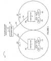
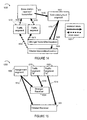
- Drawing 1300 of Figure 13 is used to illustrate superposition coding used in broadcast traffic and superposition coding used in multiple-access acknowledgement channels.
- Figure 13 includes a key 1301 illustrating that solid heavy arrows denote downlink signals while dashed heavy arrows denote uplink signals.
- Figure 13 includes a base station receiver 1302, a first user 1304, e.g., a wireless terminal, designated as the weaker receiver/transmitter, a second user 1306, e.g., a wireless terminal, designated as the stronger receiver/transmitter.
- Figure 13 also includes a downlink traffic segment 1308 and a composite downlink signal 1310 with superposition coding.
- the downlink composite traffic signal 1310 is transmitted from the base station to both users 1304, 1306 on the same downlink traffic segment 1308.
- Figure 13 also includes an uplink acknowledgment signal 1312 from user 1304 to base station receiver 1302 and an uplink acknowledgement signal 1314 from user 1306 to base station receiver 1302.
- Signal 1312 is transmitted at a low targeted receive power, while signal 1314 is transmitted at a high targeted receive power.
- the uplink acknowledgement signals 1312 and 1314 are transmitted on the same acknowledgement segment 1316 and are superimposed over the air.
- Figure 13 shows that two users 1304, 1306 receive their downlink traffic segment 1308 with superposition coding.
- the two users 1304, 1306 then send their acknowledgments 1312, 1314 on the same acknowledgment segment 1316 with different target receive power levels.
- the user who is identified as the stronger receiver of the traffic segment (receives less protected information), is automatically considered the stronger transmitter of the acknowledgment segment, and thus sends its acknowledgment targeting a higher receive power.
- user 1306 is identified as the stronger receiver of the traffic segment 1308 and is considered the stronger transmitter.
- User 1306 first decodes and removes the better protected signal meant for the weaker user 1304 and then decodes the data intended for user 1306.
- the user who is identified as the weaker receiver of the traffic segment, is automatically considered the weaker transmitter of the acknowledgment segment, and thus sends its acknowledgment targeting a lower receive power.
- user 1304 is identified as the weaker receiver of the traffic segment 1308 and is considered the weaker transmitter.
- the base station needs to send acknowledgments to multiple users.
- the downlink acknowledgment channel is treated as a broadcast channel. From the above framework of controlled superposition coding in a broadcast channel, the base station superposes the acknowledgments on the same acknowledgment segment.
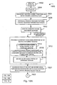
- Figure 14 shows exemplary superposition coding used in multiple-access traffic channels and exemplary superposition coding used in broadcast acknowledgement channels.
- Figure 14 includes a key 1401 illustrating that solid heavy arrows denote downlink signals while dashed heavy arrows denote uplink signals.
- Drawing 1400 of Figure 14 includes a base station receiver/transmitter 1402, a first user 1404, e.g., a wireless terminal, designated the weaker transmitter/receiver, and a second user 1406, e.g., a wireless terminal, designated the stronger transmitter/receiver.
- User 1404 transmits its uplink traffic signal 1408 at a targeted low receive power
- user 1406 transmits its uplink traffic signal 1410 at a high targeted receive power.
- Figure 14 shows that two users 1404, 1406 transmit their uplink traffic signals 1408, 1410 on the same traffic segment 1412, and the two signals are superposed over the air.
- the base station 1402 then sends two acknowledgments in a composite downlink acknowledgement signal 1416 on the same acknowledgment segment 1414 with different transmit power levels for each acknowledgement.
- the user who is identified as the stronger transmitter of the traffic segment 1412, is automatically considered the stronger receiver of the acknowledgment segment 1414, and thus the base station sends its acknowledgment at low transmit power (less protected).
- user 1406 is identified as the stronger transmitter and thus base station 1402 sends the acknowledgement signal for user 1406 at low transmit power.
- User 1406 receives signal 1416 and first decodes and removes the better protected signal meant for the weaker user 1404 and then decodes its own acknowledgement signal.
- the user who is identified as the weaker transmitter of the traffic segment 1408, is automatically considered the weaker receiver of the acknowledgment segment 1414, and thus the base station 1402 sends its acknowledgment at high transmit power (more protected).
- user 1404 is identified as the weaker transmitter and thus base station 1402 sends the acknowledgement signal for user 1404 at high transmit power.
- controlled superposition coding is used to reduce the transmit power level on common control channels used in multi-user communication systems.
- Common control channels are often used to send control information to every user in the system. As a result, they are normally transmitted at a high transmit power in order to reach the worst-case user.
- This embodiment will be described in the context of a cellular wireless communication system, but is applicable more generally.
- This exemplary embodiment assumes a common control channel that is transmitted by the base station on the downlink and monitored by wireless terminal users, e.g., each of mobile users in a cell.
- the control information is partitioned into two groups.
- the first group is referred to as 'regular information', which is intended for mainstream users.
- the set of mainstream users are those mobile users with reasonable downlink channel conditions e.g., reasonable downlink SNR.
- the second group is referred to as 'protected information', which is intended to be received by most or all of the mobile users in the system, i.e. not only mainstream users but also weaker users, which have poor downlink SNR.
- the protected control information is transmitted at high power per bit, which enables it to be received robustly by some or all of the weak users in the system.
- the regular information is then superposed on the protected information at nominal power per bit.
- the weak users may not be able to decode all the information but should be able to decode the protected information from the superposed signal, while the mainstream users will be able to decode both the protected and the regular information.
- Figure 15 is a drawing 1500 illustrating the application of superposition coding to a common control channel.
- Figure 15 includes a first user 1502, e.g., a wireless terminal, designated the weaker receiver, and a second user 1504, e.g., a wireless terminal, designated the stronger receiver.
- Figure 15 also includes an assignment segment 1506, a composite assignment signal with superposition coding 1512, a downlink traffic segment "A” 1508, and a downlink traffic segment "B” 1510. Downlink traffic segment "A” is intended for the weaker receiver 1502, while downlink traffic segment "B” is intended for the stronger receiver 1504.
- the assignment information of those two traffic segments is sent in a single assignment segment 1506 with superposition coding. Specifically, the assignment information for segment A is treated as protected information and that for segment B is treated as regular information.
- the mainstream users, e.g., user 1504 can decode both assignments and thus be scheduled in any of the traffic segments 1508, 1510. In this example, stronger receiver 1504 first decodes and removes the better protected signal meant for the weaker receiver 1502 and then decodes its assignment. On the other hand, the weak users, e.g., 1502 can only decode the assignment for segment A 1508 and thus be scheduled only in segment A 1508.
- superposition coding on the assignment channel is not necessarily tied to superposition coding on the corresponding traffic segments in this example.
- Traffic segment "A” and traffic segment “B” are distinct traffic segments and signals 1514 and 1516 are distinct signals and are not superposed.
- Superposition coding on a common control channel is a valuable practical technique in its own right, and may result in power savings as well as increased robustness.
- Figure 16 is a drawing 1600 including exemplary uplink signals on the same uplink channel segment, and is used to illustrate the concept of targeted received power in accordance with an embodiment of the invention.
- Figure 16 includes a two exemplary wireless terminals implemented in accordance with the invention, WT 1 1602, WT 2 1604, and an exemplary base station 1606, implemented in accordance with the invention.
- the channel gain between WT1 1602 and BS 1606 is G 1 1610 and is known to both WT1 1602 and BS 1606, e.g., by measurements of pilots signals and a feedback channel quality report.
- the channel gain between WT2 1604 and BS 1606 is G 2 1612 is known to both BS 1606 and WT2 1604, e.g., by measurements of pilots signals and a feedback channel quality report. Assume that both WT1 1602 and WT 2 1604 are transmitting using the same data rate, modulation, coding scheme, and coding rate. WT 1 1602 has been designated as the stronger transmitter by base station 1606 for uplink channel segment 1608, while WT 2 1604 has been designated as the weaker transmitter by base station 1606 for uplink channel segment 1608.
- Uplink signal 1614 includes the nominal power signal S 1 including WT1 uplink information and has been scaled by a transmission gain value a 1 .
- Signal 1614 is transmitted from WT1 1602 as a 1 S 1 ; however, due to the channel losses, the signal is received by the base station's receiver as a 1 G 1 S 1 (a reduced level).
- WT1 1602 knows the channel value of G 1 .
- WT1 1602 has pre-adjusted the value of a 1 to achieve a high received power target represented by a 1 G 1 .
- the channel gain between WT2 1604 and BS 1606 is G 2 1612 is known to both BS 1606 and WT2 1604, e.g., by measurements of pilots signals and a feedback channel quality report.
- WT21604 transmits uplink signal 1616 to the BS 1606.
- Uplink signal 1616 includes nominal power signal S 2 including WT2 uplink information and has been scaled by a transmission gain value a 2 .
- Signal 1616 leaves the WT as a 2 S 2 ; however, due to the channel losses, the signal is received by the base station's receiver as a 2 G 2 S 2 (a reduced level).
- WT2 1604 knows the channel value of G 2 .
- WT2 has pre-adjusted the value of a 2 to achieve a low received power target represented by a 2 G 2 . Since the two signals 1614 and 1616 were transmitted on the same uplink channel segment 1608, the signals superposed in the air and were received by base station 1606 as a combined signal (a 1 G 1 )S 1 + (a 2 G 2 )S 2 1618.
- the two received power targets were chosen such that the high power target, represented by a 1 G 1 is greater, e.g., much greater, than the low power target represented by a 2 G 2 .
- the BS can differentiate between the two signals from the two independent devices (WT1 1602, WT2 1604) and extract the information from signals S 1 and S 2 . Note that at can be less than a 2 depending upon the channel gains.
- FIG. 17 is a flowchart 1700 of an exemplary method of operating a base station (BS) in accordance with the present invention.
- the exemplary method of flowchart 1700 uses controlled superposition in accordance with the present invention.
- base station operation starts, e.g., the base station is powered on and initialized. Operation proceeds from step 1702 to step 1704.
- the BS monitors to receive signals, e.g., uplink signals from WTs. Operation proceeds from step 1704 to steps 1706 and 1722.
- the BS receives channel quality reports from a plurality of WTs.
- the BS maintains a set of channel condition information indicating the channel quality of each of a plurality of WTs.
- the maintained set of channel condition information includes, e.g., separate channel signal to noise ratio information for each of the plurality of WTs. Operation proceeds from step 1708 to step 1710.
- the BS examines the set of channel condition information to identify WTs having channel conditions which differ from one another by at least a pre-selected minimum amount, e.g., 3 dB or 5dB or 10 dB.
- the BS determines if there are at least two WTs identified as having channel conditions which differ by at least the pre-selected minimum amount, that have signals to be transmitted in a communications channel segment which is available to be assigned.
- step 1714 the BS assigns a communications channel segment to be used to communicate superimposed signals corresponding to at least two different WTs identified as having channel conditions which differ by at least the pre-selected minimum amount, e.g., a first WT which has a better channel quality (by at least the pre-selected minimum amount) than a second WT.
- the assigned communication channel segment may be, e.g., a downlink channel segment that is an assignment channel segment used to communicate uplink communications channel segment assignments, e.g, uplink traffic channel segment assignments, to WTs.
- step 1716 the base station transmits a superimposed signal to the two different identified WTs, the first WT, and the second WT, e.g., an assignment channel segment corresponding to the communications channel segment being assigned, said superimposed signal including a low power signal portion intended for said first WT and a high power signal portion intended for said second wireless terminal, the lower power signal portion being transmitted by said BS with lower power than said high power signal portion.
- step 1704 the base station monitors for additional signals.
- step 1712 If it is determined in step 1712, that there are not at least two WTs identified having channel conditions which differ by at least the pre-selected minimum amount having signals to be transmitted in a communications channel segment which is available to be assigned, then operation proceeds to step 1718.
- the BS assigns the available communications channel segment to a single one of said plurality of WTs. Operation proceeds from step 1718 to step 1720.
- step 1720 the base station transmits an assignment signal to said single one WT. Operation proceeds from step 1720 to step 1704, in which the BS continues to monitor for signals.
- step 1722 the base station receives a superimposed signal from said first and second WTs, said superimposed signal including first and second signal portions transmitted by said first and second WTs, respectively, said first signal portion being received by said BS at a higher power level than said second signal portion. Operation proceeds from step 1722 to step 1724. In step 1724, the BS decodes first signal portion; subtracts the first signal portion from the said superimposed signal; and then decodes said second signal portion. Operation proceeds from step 1724 to step 1704, in which the base station continues to monitor to receive signals.
- Figure 18 illustrates the steps performed by a WT in accordance with one exemplary embodiment of the invention where superimposed uplink channel assignment messages are used to assign uplink traffic channel segments to WTs.
- the assignment message intended for a particular WT includes the WT's particular terminal identifier.
- the transmission of the assignment message (e.g., terminal ID) to the WT with the better channel condition is on the low power portion of the superimposed assignment message signal while the assignment to the WT with the poorer channel condition is on the high power portion of the superimposed assignment message signal.
- the method 1800 begins in start step 1802.
- step 1804 the WT is initialized, e.g., as part of a power on operation.
- step 1806 the WT periodically measures the channel conditions and reports the channel conditions to the BS with which it is interacting.
- the WT receives transmission power control adjustment information from the BS in step 1808 on a periodic basis. Based on this information the WT can predict what the received power will be at the BS for a particular transmission power level.
- the BS power control information allows the WT to determine a transmission power level required to meet a target received power level.
- the WT stores information, e.g., a table including different gain coefficients that can be used to achieve different received power levels, which can be used in combination with the WT feedback information which indicates the transmission power required to achieve a particular reference level.
- the gain coefficients can be used as offsets from the gain required to achieve the particular reference level thereby resulting in the received power level associated with the gain coefficient when used to adjust the transmission power level in combination with the received power control feedback information.
- Step 1810 Monitoring for channel assignment messages occurs in step 1810. Steps 1806, 1808 and 1810 are performed on an ongoing basis while the WT operates in an active state. For each assignment message received in step 1810 operation proceeds to step 1812. In step 1812, a superposition decoding operation is performed on the received assignment message which is a superimposed signal including a first signal part and a second signal part where the first and second signal parts are transmitted at different power levels with the first signal part being the higher power part.
- the decoding step 1812 includes substep 1814 in which the first signal portion, e.g., the high power portion, is decoded. Then in step 1816 the first signal portion is substracted from the received assignment message to produce the second (low power) signal portion which is decoded in substep 1818. If the WT has poor channel conditions, it may only be able to decode the first, high power, signal portion, for this reason the BS uses the high power signal portion to communicate assignment information to the WT having the poorer communications channel.
- step 1820 the decoding result is examined to determine which one of the first and second signal portions was intended for the WT, e.g., the WT checks to determine which portion includes its particular WT identifier. Assuming the WT has the better channel conditions of the WTs to which the segment is being assigned, the WT will detect its ID in the low power signal portion of the transmitted signal.
- step 1824 the WT determines if the portion of the assignment message which was intended for the WT was the low or high power portion of the received assignment message.
- step 1826 the WT determines from the power level information determined in step 1824 which one of a plurality of received target power levels to use in transmitting information to the BS in the assigned segment corresponding to the received assignment message. From the determined received target power level, the stored gain coefficient information corresponding to the determined received target power level and the power control feedback information, the WT determines in step 1828 the transmission power level required to achieve the determined received target power level at the BS.
- the WT transmits a signal to the BS using the determined transmission power level in the assigned uplink channel segment.
- the transmitted signal will combine with a portion of a signal from another WT in the air to form a portion of a superimposed signal that will be received by the BS.
- the transmitted signal will be a high power signal portion of the superimposed signal received by the BS as a result of the determined transmission power level in cases where the assignment message intended for the WT was determined to be a low power portion of the assignment message.
- the transmitted signal will be a low power signal portion of the superimposed signal received by the BS as a result of the determined transmission power level in cases where the assignment message intended for the WT was determined to be a high power portion of the assignment message.
- nodes described herein are implemented using one or more modules to perform the steps corresponding to one or more methods of the present invention, for example, signal processing, message generation and/or transmission steps.
- modules may be implemented using software, hardware or a combination of software and hardware.
- Many of the above described methods or method steps can be implemented using machine executable instructions, such as software, included in a machine readable medium such as a memory device, e.g., RAM, floppy disk, etc. to control a machine, e.g., general purpose computer with or without additional hardware, to implement all or portions of the above described methods, e.g., in one or more nodes.
- the present invention is directed to a machine-readable medium including machine executable instructions for causing a machine, e.g., processor and associated hardware, to perform one or more of the steps of the above-described method(s).
- the methods and apparatus of the present invention may be, and in various embodiments are, used with CDMA, orthogonal frequency division multiplexing (OFDM), and/or various other types of communications techniques which may be used to provide wireless communications links between access nodes and mobile nodes.
- the access nodes are implemented as base stations which establish communications links with mobile nodes using OFDM and/or CDMA.
- the mobile nodes are implemented as notebook computers, personal data assistants (PDAs), or other portable devices including receiver/transmitter circuits and logic and/or routines, for implementing the methods of the present invention.
Landscapes
- Engineering & Computer Science (AREA)
- Signal Processing (AREA)
- Computer Networks & Wireless Communication (AREA)
- Mobile Radio Communication Systems (AREA)
- Time-Division Multiplex Systems (AREA)
- Compression, Expansion, Code Conversion, And Decoders (AREA)
- Reduction Or Emphasis Of Bandwidth Of Signals (AREA)
Claims (27)
- Ein Kommunikationsverfahren (1700) zur Verwendung in einem Kommunikationssystem (300), das eine Basisstation (306, 308; 400) und eine Vielzahl von Drahtlosendgeräten bzw. -terminals (310, 312, 318, 320; 500) beinhaltet, wobei ein Kommunikationskanal (314, 316, 322, 324) zwischen jedem Drahtlosendgerät der Vielzahl von Drahtlosendgeräten und der Basisstation vorliegt, wobei der Kommunikationskanal, der zwischen jedem bestimmten Drahtlosendgerät und der Basisstation vorliegt, eine Qualität hat, die die Kanalqualität für das bestimmte Drahtlosendgerät ist, wobei das Verfahren Folgendes aufweist:Betreiben der Basisstation zum:i) Unterhalten (1708) eines Satzes von Kanalzustandsinformation, die die Kanalqualität jedes der Vielzahl von Drahtlosendgeräten anzeigt;ii) Untersuchen (1710) des Satzes von Kanalzustandsinformation zum Identifizieren von Drahtlosendgeräten, die Kanalzustände haben, die sich voneinander unterscheiden, und zwar mindestens um einen vorausgewählten Minimalbetrag; undiii) Zuweisen (1714) eines Kommunikationskanalsegments, das verwendet werden soll zum Kommunizieren von überlagerten Signalen entsprechend wenigstens zwei unterschiedlichen Drahtlosendgeräten, von denen bestimmt wurde, dass sie Kanalzustände haben, die sich um mindestens den vorausgewählten Minimalbetrag unterscheiden.
- Kommunikationsverfahren nach Anspruch 1,
wobei der unterhaltene Satz von Kanalzustandsinformation Information zum Kanalsignal-zu-Rauschen-Verhältnis beinhaltet;
wobei die wenigstens zwei unterschiedlichen Drahtlosendgeräte ein erstes und ein zweites Drahtlosendgerät beinhalten; und
wobei der minimale vorausgewählte Betrag, um den sich die Kanalzustände der ersten und zweiten Drahtlosendgeräte unterscheiden, 3 dB ist. - Verfahren nach Anspruch 1, das weiter Folgendes aufweist:Betreiben der Basisstation zum Wiederholen der Schritte des Unterhaltens, Untersuchens und Zuweisens.
- Verfahren nach Anspruch 1, das weiter Folgendes aufweist:Betreiben der Basisstation zum Wiederholen der Schritte des Unterhaltens und Untersuchens; undwobei, wenn der Untersuchungsschritt dabei versagt, wenigstens zwei Drahtlosendgeräte zu bestimmen, die Kanalzustände haben, die sich um den vorausgewählten Minimalbetrag unterscheiden, die Signale haben, die in einem Kommunikationssegment gesendet werden sollen, das zum Zuweisen zur Verfügung steht, die Basisstation betrieben wird zum:Zuweisen des verfügbaren Kommunikationskanalsegments zu einem Einzelnen der Vielzahl von Drahtlosendgeräten.
- Kommunikationsverfahren nach Anspruch 1,
wobei die wenigstens zwei unterschiedlichen Drahtlosendgeräte ein erstes Drahtlosendgerät und ein zweites Drahtlosendgerät beinhalten;
wobei das zugewiesene Kommunikationskanalsegment ein Segment eines Downlink- bzw. Abwärtsverbindungskanals ist;
wobei das erste Drahtlosendgerät eine bessere Kanalqualität hat als das zweite Drahtlosendgerät, wobei das Verfahren weiter Folgendes aufweist:Betreiben der Basisstation zum Senden eines ersten überlagerten Signals an das erste und zweite Drahtlosendgerät in dem zugewiesenen Kommunikationskanalsegment, wobei das erste überlagerte Signal einen Signalabschnitt mit niedriger Leistung beinhaltet, der für das erste Drahtlosendgerät vorgesehen ist und einen Signalabschnitt mit hoher Leistung beinhaltet, der für das zweite Drahtlosendgerät vorgesehen ist, wobei der Signalabschnitt mit niedrigerer Leistung von der Basisstation mit niedrigerer Leistung gesendet wird als der Signalabschnitt mit hoher Leistung, oder weniger Codierungsschutz hat als der Signalabschnitt mit hoher Leistung. - Kommunikationsverfahren nach Anspruch 5, wobei das zugewiesene Kommunikationskanalsegment ein Segment eines Zuweisungskanals ist, der zum Kommunizieren von Kommunikationskanalsegmentzuweisungen an Drahtlosendgeräte verwendet wird.
- Kommunikationsverfahren nach Anspruch 6, das weiter Folgendes aufweist:Betreiben der Basisstation zum:Empfangen eines zweiten überlagerten Signals von den ersten und zweiten Drahtlosendgeräten, wobei das empfangene zweite überlagerte Signal erste und zweite Signalabschnitte beinhaltet, die von dem ersten bzw. zweiten Drahtlosendgerät gesendet werden, wobei der erste Signalabschnitt, von der Basisstation mit einem höheren Leistungspegel empfangen wird als der zweite Signalabschnitt.
- Kommunikationsverfahren nach Anspruch 7, das weiter Folgendes aufweist:Betreiben der Basisstation zum:Decodieren des ersten Signalabschnittes;Subtrahieren des ersten Signalabschnittes von dem zweiten überlagerten Signal; undDecodieren des zweiten Signalabschnittes.
- Kommunikationsverfahren nach Anspruch 7, das weiter Folgendes aufweist:Betreiben des ersten Drahtlosendgeräts zum Bestimmen, welcher einer Vielzahl von empfangenen Zielleistungspegeln verwendet werden soll beim Bestimmen der Sendeleistung, die verwendet werden soll zum Senden des ersten Signalabschnittes, und zwar aus dem ersten überlagerten Signal, das an das erste und zweite Drahtlosendgerät in dem Segment eines Zuweisungskanals gesendet worden ist.
- Kommunikationsverfahren nach Anspruch 9, wobei das Betreiben des ersten Drahtlosendgeräts zum Bestimmen, welcher einer Vielzahl von empfangenen Zielleistungspegeln verwendet werden soll, Folgendes beinhaltet:Bestimmen, ob der Abschnitt des ersten überlagerten Signals, das verwendet wird um Uplink- bzw. Aufwärtsverbindungs-Kanalzuweisungsinformation an das erste Drahtlosendgerät zu kommunizieren, als ein Signalabschnitt mit niedriger Leistung oder als ein Signalabschnitt mit hoher Leistung gesendet wurde.
- Eine Basisstation (400) zur Verwendung in einem Kommunikationssystem (300), das eine Vielzahl von Drahtlosendgeräten (310, 312, 318, 320, 500) beinhaltet, wobei ein Kommunikationskanal (314, 316, 322, 324) zwischen jedem Drahtlosendgerät der Vielzahl von Drahtlosendgeräten und der Basisstation vorliegt, wobei der Kommunikationskanal, der zwischen jedem bestimmten Drahtlosendgerät und der Basisstation vorliegt, eine Qualität hat, die die Kanalqualität für das bestimmte Drahtlosendgerät ist, wobei die Basisstation Folgendes aufweist:Mittel zum Unterhalten eines Satzes von Kanalzustandsinformation, die die Kanalqualität jedes der Vielzahl von Drahtlosendgeräten anzeigt;Mittel zum Untersuchen des Satzes von Kanalzustandsinformation zum Identifizieren von Drahtlosendgeräten, die Kanalzustände haben, die sich voneinander um einen vorausgewählten Minimalbetrag unterscheiden; undMittel zum Zuweisen eines Kommunikationskanalsegments, das verwendet werden soll zum Kommunizieren von überlagerten Signalen entsprechend wenigstens zwei unterschiedlichen Drahtlosendgeräten, von denen bestimmt wurde, dass sie Kanalzustände haben, die sich um wenigstens den vorausgewählten Minimalbetrag unterscheiden.
- Basisstation nach Anspruch 11,
wobei die wenigstens zwei unterschiedlichen Drahtlosendgeräte ein erstes und ein zweites Drahtlosendgerät aufweisen;
wobei der unterhaltene Satz von Kanalzustandsinformation Information zum Kanalsignal-zu-Rauschen-Verhältnis beinhaltet; und
wobei der minimale vorausgewählte Betrag, um den sich die Kanalzustände eines ersten und zweiten Drahtlosendgeräts unterscheiden, 3 dB ist. - Basisstation nach Anspruch 11, die weiter Folgendes aufweist:Mittel zum Zuweisen eines verfügbaren Kommunikationskanalsegments an eine einzelnes Drahtlosendgerät der Vielzahl von Drahtlosendgeräten, wenn die Untersuchungsmittel dabei versagen, wenigstens zwei Drahtlosendgeräte zu bestimmen, die Kanalzustände haben, die sich um den vorausgewählten Minimalbetrag unterscheiden, die Signale haben, die in einem Kommunikationssegment gesendet werden sollen, das zum Zuweisen zur Verfügung steht.
- Basisstation nach Anspruch 13, die weiter Folgendes aufweist:einen Empfänger zum Empfangen eines überlagerten Signals von dem ersten und zweiten Drahtlosendgerät, wobei das empfangene überlagerte Signal erste und zweite Signalabschnitte beinhaltet, die von dem ersten bzw. zweiten Drahtlosendgerät gesendet wurden, wobei der erste Signalabschnitt durch die Basisstation mit einem höheren Leistungspegel empfangen wird als der zweite Signalabschnitt, wobei das erste Drahtlosendgerät einen besseren Kanalzustand hat als das zweite Drahtlosendgerät.
- Basisstation nach Anspruch 14, die weiter Folgendes aufweist:einen Überlagerungsdecodierer zum Decodieren der ersten und zweiten Signalabschnitte des empfangenen überlagerten Signals.
- Basisstation nach Anspruch 15, wobei der Überlagerungsdecodierer Folgendes beinhaltet:eine Decodierervorrichtung zum Decodieren des ersten Signalabschnittes;einen Subtrahierer zum Subtrahieren des ersten Signalabschnittes von dem überlagerten Signal zum Erzeugen eines zweiten Signalabschnittes; undeine zweite Decodierervorrichtung zum Decodieren des zweiten Signalabschnittes.
- Ein Kommunikationsverfahren zur Verwendung in einem Kommunikationssystem (300), das eine Basisstation (306, 308, 400) und eine Vielzahl von Drahtlosendgeräten (310, 316, 318, 320, 500) beinhaltet, wobei ein Kommunikationskanal (314, 316, 322, 324) zwischen jedem Drahtlosendgerät der Vielzahl von Drahtlosendgeräten und der Basisstation vorliegt, wobei der Kommunikationskanal, der zwischen jedem bestimmten Drahtlosendgerät und der Basisstation vorliegt, eine Qualität hat, die die Kanalqualität für das bestimmte Drahtlosendgerät ist, wobei das Verfahren Folgendes aufweist:Betreiben eines ersten Drahtlosendgerätes mit einer ersten Kanalqualität zum Senden eines ersten Abschnittes eines überlagerten Kommunikationssignals an die Basisstation;Betreiben eines zweiten Drahtlosendgeräts mit einer zweiten Kanalqualität zum Senden eines zweiten Abschnittes des überlagerten Kommunikationssignals an die Basisstation, wobei sich die ersten und zweiten Kanalqualitäten um mindestens einen vorausgewählten Betrag unterscheiden, wobei sich die ersten und zweiten Signalabschnitte in der Luft während der Sendung an die Basisstation sich kombinieren bzw. vereinigen, so dass sie ein überlagertes Kommunikationssignal bilden; undBetreiben der ersten und zweiten Drahtlosendgeräte zum Empfangen, vor der Sendung der ersten und zweiten überlagerten Signalabschnitte, eines überlagerten Zuweisungssignals, das einen Signalabschnitt mit niedriger Leistung beinhaltet, der für das erste Drahtlosendgerät vorgesehen ist und einen Signalabschnitt mit hoher Leistung, der für das zweite Drahtlosendgerät vorgesehen ist, wobei der Signalabschnitt mit niedrigerer Leistung mit niedrigerer Leistung durch die Basisstation gesendet wird als der Signalabschnitt mit hoher Leistung, wobei das erste Drahtlosendgerät eine bessere Kanalqualität hat als das zweite Drahtlosendgerät, wobei das überlagerte Zuweisungssignal durch die Basisstation verwendet werden kann zum Zuweisen eines Uplink-Kommunikationskanalsegments.
- Kommunikationsverfahren nach Anspruch 17,
wobei der vorausgewählte Betrag, um den sich die Kanalqualität der ersten und zweiten Endgeräte unterscheidet, 3 dB ist. - Kommunikationsverfahren nach Anspruch 17, wobei die ersten und zweiten Signalabschnitte, die vom ersten bzw. zweiten Drahtlosendgerät gesendet werden, mit Leistungspegeln gesendet werden, die bewirken, dass der erste Signalabschnitt von der Basisstation bei einem höheren Leistungspegel empfangen wird als der zweite Signalabschnitt.
- Kommunikationsverfahren nach Anspruch 19, das weiter Folgendes aufweist:Betreiben des ersten Drahtlosendgeräts zum Bestimmen, welcher einer Vielzahl von empfangenen Zielleistungspegein verwendet werden soll beim Bestimmen der Sendeleistung, die verwendet werden soll zum Senden des ersten Signalabschnittes von dem überlagerten Zuweisungssignal.
- Kommunikationsverfahren nach Anspruch 20, wobei das Betreiben des ersten Drahtlosendgeräts zum Bestimmen, welcher einer Vielzahl von empfangenen Zielleistungspegeln verwendet werden soll, Folgendes aufweist. Bestimmen, ob der überlagerte Signalabschnitt, der zum Kommunizieren von Uplink-Kanalzuweisungsinformation an das erste Drahtlosendgerät verwendet wird, als ein Signalabschnitt mit niedriger Leistung oder ein Signalabschnitt mit hoher Leistung gesendet wurde.
- Ein Drahtlosendgerät (310, 312, 318, 320, 500), das Folgendes aufweist:einen Empfänger (502) zum Empfangen eines überlagerten Zuweisungssignals, das zum Kommunizieren von Uplink-Kanalzuweisungsinformation an das Drahtlosendgerät verwendet wird, das einen ersten Signalabschnitt und einen zweiten Signalabschnitt beinhaltet, wobei einer der Signalabschnitte für das Drahtlosendgerät vorgesehen ist, wobei der andere der Signalabschnitte für ein anderes Drahtlosendgerät vorgesehen ist, wobei der erste Signalabschnitt mit einem niedrigeren Leistungspegel empfangen wird als der zweite Signalabschnitt, und zwar über einen ersten Kanal, der eine bessere Qualität hat als ein zweiter Kanal, der von dem anderen Drahtlosendgerät verwendet wird;einen Überlagerungsdecodierer zum Decodieren der ersten und zweiten Signalabschnitte;Mittel zum Bestimmen von Information, die in einem der ersten und zweiten Signalabschnitte enthalten ist, darüber, welcher Abschnitt für das Drahtlosendgerät vorgesehen ist, wobei die Mittel zum Bestimmen weiter ausgelegt sind zum Bestimmen, ob ein Abschnitt des empfangenen überlagerten Zuweisungssignals als ein Signalabschnitt mit niedriger Leistung oder ein Signalabschnitt mit hoher Leistung gesendet wurde; undeinen Sender (504) zum Senden von Signalen in Uplink-Kommunikationskanalsegmenten, denen das überlagerte Zuweisungssignal, das für das Drahtlosendgerät vorgesehen ist, entspricht.
- Drahtlosendgerät nach Anspruch 22, das weiter Folgendes aufweist:Mittel zum Speichern der empfangenen Zielpegelleistungsinformation für eine Vielzahl von unterschiedlichen empfangenen Zielleistungspegeln; undMittel zum Bestimmen, welcher der Vielzahl von empfangenen Zielleistungspegeln verwendet werden soll beim Senden eines Signals in einem bestimmten Uplink-Kommunikationskanalsegment, und zwar basierend auf dem empfangenen überlagerten Zuweisungssignal, das dem bestimmten Uplink-Kommunikationskanalsegment entspricht.
- Kommunikationsverfahren nach Anspruch 1, wobei das Verfahren weiter Folgendes aufweist:Betreiben der Basisstation zum:Auswählen, basierend auf dem Satz von Kanalzustandsinformation, eines ersten Drahtlosendgeräts und eines zweiten Drahtlosendgeräts, um ein Uplink-Kommunikationskanalsegment zu teilen bzw. gemeinsam zu nutzen, wobei die ersten und zweiten Drahtlosendgeräte unterschiedliche Drahtlosendgerät-Kommunikationskanalqualitäten haben;Zuweisen des Uplink-Kommunikationskanalsegments, das gleichzeitig durch das erste Drahtlosendgerät und das zweite Drahtlosendgerät verwendet werden soll;Senden, an das ausgewählte erste und zweite Drahtlosendgerät, von Information, die das zugewiesene Kommunikationskanalsegment anzeigt und anzeigt, welches der ersten und zweiten Drahtlosendgeräte Signale senden sollte, die von der Basisstation bei einem höheren Leistungspegel empfangen werden sollen;Empfangen eines zusammengesetzten Signals von dem Uplink-Kommunikationskanalsegment, wobei das zusammengesetzte Signal ein erstes Signal beinhaltet, das vom ersten Drahtlosendgerät gesendet wurde und ein zweites Signal, das vom zweiten Drahtlosendgerät gesendet wurde; undDurchführen einer Überlagerungsdecodieroperation auf dem empfangenen zusammengesetzten Signal, um die ersten und zweiten Signale, die in dem zusammengesetzten Signal enthalten sind, zu decodieren.
- Verfahren nach Anspruch 24, wobei das eine der ersten und zweiten Drahtlosendgeräte, das die besseren Kanalzustände hat, an der Basisstation mit dem höheren Leistungspegel empfangen werden soll, wobei das Verfahren weiter Folgendes aufweist:Betreiben des ersten Drahtlosendgeräts zum Senden eines ersten Signalabschnittes an die Basisstation in dem zugewiesenen Uplink-Kommunikationskanalsegment; undBetreiben des zweiten Drahtlosendgeräts zum Senden eines zweiten Signalabschnittes an die Basisstation in dem zugewiesenen Uplink-Kommunikationskanalsegment, wobei die ersten und zweiten Signalabschnitte während der Sendung an die Basisstation sich überlagern.
- Verfahren nach Anspruch 25, wobei das erste Drahtlosendgerät den ersten Signalabschnitt unter Verwendung von weniger Leistung als der Leistung, die vom zweiten Drahtlosendgerät zum Senden des zweiten Signalabschnittes genutzt wird, sendet, wobei aber der erste Signalabschnitt von der Basisstation mit einem Leistungspegel empfangen wird, der höher ist als der Leistungspegel des zweiten Signalabschnittes, der von der Basisstation empfangen wird.
- Verfahren nach Anspruch 26,
wobei das erste Drahtlosendgerät eine bessere Kanalqualität hat als das zweite Drahtlosendgerät; und
wobei das Betreiben der Basisstation zum Senden weiter Folgendes aufweist:Betreiben der Basisstation zum Senden eines überlagerten Signals an die ersten und zweiten Drahtlosendgeräte, wobei das überlagerte Signal der Information entspricht, die das Uplink-Kommunikationskanalsegment anzeigt, wobei das überlagerte Signal einen Signalabschnitt mit niedriger Leistung beinhaltet, der für das erste Drahtlosendgerät vorgesehen ist, und einen Signalabschnitt mit hoher Leistung, der für das zweite Drahtlosendgerät vorgesehen ist, wobei der Signalabschnitt mit niedrigerer Leistung durch die Basisstation mit einer niedrigeren Leistung gesendet wird als der Signalabschnitt mit hoher Leistung.
Priority Applications (1)
| Application Number | Priority Date | Filing Date | Title |
|---|---|---|---|
| EP12001311.5A EP2461516B1 (de) | 2003-02-19 | 2004-02-19 | Gesteuerte Überlagerungscodierung in Kommunikationssystem mit mehreren Nutzern |
Applications Claiming Priority (7)
| Application Number | Priority Date | Filing Date | Title |
|---|---|---|---|
| US640718 | 1984-08-14 | ||
| US44852803P | 2003-02-19 | 2003-02-19 | |
| US448528P | 2003-02-19 | ||
| US47100003P | 2003-05-16 | 2003-05-16 | |
| US471000P | 2003-05-16 | ||
| US10/640,718 US8190163B2 (en) | 2002-08-08 | 2003-08-13 | Methods and apparatus of enhanced coding in multi-user communication systems |
| PCT/US2004/004947 WO2004075470A2 (en) | 2003-02-19 | 2004-02-19 | Controlled superposition coding in multi-user communication systems |
Related Child Applications (1)
| Application Number | Title | Priority Date | Filing Date |
|---|---|---|---|
| EP12001311.5 Division-Into | 2012-02-28 |
Publications (3)
| Publication Number | Publication Date |
|---|---|
| EP1597883A2 EP1597883A2 (de) | 2005-11-23 |
| EP1597883A4 EP1597883A4 (de) | 2009-06-10 |
| EP1597883B1 true EP1597883B1 (de) | 2012-11-21 |
Family
ID=32872775
Family Applications (2)
| Application Number | Title | Priority Date | Filing Date |
|---|---|---|---|
| EP04712817A Expired - Lifetime EP1602184B1 (de) | 2003-02-19 | 2004-02-19 | Verfahren und Vorrichtungen für Kodierung in Mehrbenutzer-Kommunikationssystemen |
| EP04712896A Expired - Lifetime EP1597883B1 (de) | 2003-02-19 | 2004-02-19 | Gesteuerte Superpositionscodierung in Mehrbenutzer-Kommunikationssystemen |
Family Applications Before (1)
| Application Number | Title | Priority Date | Filing Date |
|---|---|---|---|
| EP04712817A Expired - Lifetime EP1602184B1 (de) | 2003-02-19 | 2004-02-19 | Verfahren und Vorrichtungen für Kodierung in Mehrbenutzer-Kommunikationssystemen |
Country Status (11)
| Country | Link |
|---|---|
| US (2) | US7411895B2 (de) |
| EP (2) | EP1602184B1 (de) |
| JP (2) | JP4718442B2 (de) |
| KR (2) | KR101061654B1 (de) |
| CN (1) | CN101801078B (de) |
| AU (2) | AU2004213988B2 (de) |
| BR (2) | BRPI0407628B1 (de) |
| CA (2) | CA2516359C (de) |
| ES (1) | ES2397385T3 (de) |
| MX (1) | MXPA05008892A (de) |
| WO (2) | WO2004075442A2 (de) |
Cited By (1)
| Publication number | Priority date | Publication date | Assignee | Title |
|---|---|---|---|---|
| EP4675948A1 (de) | 2024-07-01 | 2026-01-07 | Technische Universität München, in Vertretung des Freistaats Bayern | Signalübertragungsverfahren und sender |
Families Citing this family (180)
| Publication number | Priority date | Publication date | Assignee | Title |
|---|---|---|---|---|
| US7295509B2 (en) | 2000-09-13 | 2007-11-13 | Qualcomm, Incorporated | Signaling method in an OFDM multiple access system |
| US9130810B2 (en) | 2000-09-13 | 2015-09-08 | Qualcomm Incorporated | OFDM communications methods and apparatus |
| US8019068B2 (en) * | 2000-12-01 | 2011-09-13 | Alcatel Lucent | Method of allocating power for the simultaneous downlink conveyance of information between multiple antennas and multiple destinations |
| US7363039B2 (en) | 2002-08-08 | 2008-04-22 | Qualcomm Incorporated | Method of creating and utilizing diversity in multiple carrier communication system |
| US6961595B2 (en) | 2002-08-08 | 2005-11-01 | Flarion Technologies, Inc. | Methods and apparatus for operating mobile nodes in multiple states |
| US8190163B2 (en) | 2002-08-08 | 2012-05-29 | Qualcomm Incorporated | Methods and apparatus of enhanced coding in multi-user communication systems |
| US7042857B2 (en) * | 2002-10-29 | 2006-05-09 | Qualcom, Incorporated | Uplink pilot and signaling transmission in wireless communication systems |
| JP4718442B2 (ja) | 2003-02-19 | 2011-07-06 | クゥアルコム・インコーポレイテッド | マルチユーザ通信システムにおける制御重畳コーディング |
| US9661519B2 (en) | 2003-02-24 | 2017-05-23 | Qualcomm Incorporated | Efficient reporting of information in a wireless communication system |
| US9544860B2 (en) | 2003-02-24 | 2017-01-10 | Qualcomm Incorporated | Pilot signals for use in multi-sector cells |
| US7218948B2 (en) | 2003-02-24 | 2007-05-15 | Qualcomm Incorporated | Method of transmitting pilot tones in a multi-sector cell, including null pilot tones, for generating channel quality indicators |
| US8811348B2 (en) | 2003-02-24 | 2014-08-19 | Qualcomm Incorporated | Methods and apparatus for generating, communicating, and/or using information relating to self-noise |
| US7640373B2 (en) * | 2003-04-25 | 2009-12-29 | Motorola, Inc. | Method and apparatus for channel quality feedback within a communication system |
| US7177297B2 (en) | 2003-05-12 | 2007-02-13 | Qualcomm Incorporated | Fast frequency hopping with a code division multiplexed pilot in an OFDMA system |
| US8593932B2 (en) | 2003-05-16 | 2013-11-26 | Qualcomm Incorporated | Efficient signal transmission methods and apparatus using a shared transmission resource |
| US7925291B2 (en) | 2003-08-13 | 2011-04-12 | Qualcomm Incorporated | User specific downlink power control channel Q-bit |
| US7623553B2 (en) * | 2003-11-03 | 2009-11-24 | Qualcomm Incorporated | Method, apparatus, and system for data transmission and processing in a wireless communication environment |
| JP2007516662A (ja) * | 2003-11-07 | 2007-06-21 | シャープ株式会社 | ネットワークチャンネルの特性値の測定およびネットワーク管理のシステムおよび方法 |
| US8213301B2 (en) * | 2003-11-07 | 2012-07-03 | Sharp Laboratories Of America, Inc. | Systems and methods for network channel characteristic measurement and network management |
| US8611283B2 (en) * | 2004-01-28 | 2013-12-17 | Qualcomm Incorporated | Method and apparatus of using a single channel to provide acknowledgement and assignment messages |
| US7864725B2 (en) | 2004-01-29 | 2011-01-04 | Neocific, Inc. | Methods and apparatus for overlaying multi-carrier and direct sequence spread spectrum signals in a broadband wireless communication system |
| KR100922950B1 (ko) * | 2004-03-05 | 2009-10-22 | 삼성전자주식회사 | 직교주파수분할다중접속 방식을 기반으로 하는 이동통신시스템에서 데이터 프레임 처리 결과 송/수신장치 및 방법 |
| US7342958B2 (en) * | 2004-06-24 | 2008-03-11 | Lucent Technologies Inc | System and method for enhancing throughput in an additive gaussian noise channel with a predetermined rate set and unknown interference |
| US9148256B2 (en) | 2004-07-21 | 2015-09-29 | Qualcomm Incorporated | Performance based rank prediction for MIMO design |
| US9137822B2 (en) | 2004-07-21 | 2015-09-15 | Qualcomm Incorporated | Efficient signaling over access channel |
| US8891349B2 (en) | 2004-07-23 | 2014-11-18 | Qualcomm Incorporated | Method of optimizing portions of a frame |
| KR20070038534A (ko) * | 2004-07-30 | 2007-04-10 | 마츠시타 덴끼 산교 가부시키가이샤 | 기지국 장치 및 무선 통신 방법 |
| US8503938B2 (en) | 2004-10-14 | 2013-08-06 | Qualcomm Incorporated | Methods and apparatus for determining, communicating and using information including loading factors which can be used for interference control purposes |
| JP2008517539A (ja) | 2004-10-14 | 2008-05-22 | クゥアルコム・フラリオン・テクノロジーズ、インコーポレイテッド | 干渉制御のために使用され得る情報を決定し、伝達し、使用する方法および装置 |
| KR101141649B1 (ko) | 2004-11-09 | 2012-05-17 | 엘지전자 주식회사 | 고속의 상향 데이터 전송을 위한 데이터 채널의 제어정보송수신 방법 |
| US8831115B2 (en) | 2004-12-22 | 2014-09-09 | Qualcomm Incorporated | MC-CDMA multiplexing in an orthogonal uplink |
| US7453849B2 (en) * | 2004-12-22 | 2008-11-18 | Qualcomm Incorporated | Method of implicit deassignment of resources |
| US8238923B2 (en) | 2004-12-22 | 2012-08-07 | Qualcomm Incorporated | Method of using shared resources in a communication system |
| US7477622B2 (en) * | 2005-01-28 | 2009-01-13 | Qualcomm, Incorporated | Superposition coding in a wireless communication system |
| US8811273B2 (en) * | 2005-02-22 | 2014-08-19 | Texas Instruments Incorporated | Turbo HSDPA system |
| CN101171818B (zh) * | 2005-03-08 | 2013-05-08 | 高通股份有限公司 | 结合脉冲调制和分层调制的发射方法和装置 |
| US9246560B2 (en) | 2005-03-10 | 2016-01-26 | Qualcomm Incorporated | Systems and methods for beamforming and rate control in a multi-input multi-output communication systems |
| US9154211B2 (en) | 2005-03-11 | 2015-10-06 | Qualcomm Incorporated | Systems and methods for beamforming feedback in multi antenna communication systems |
| US9461859B2 (en) | 2005-03-17 | 2016-10-04 | Qualcomm Incorporated | Pilot signal transmission for an orthogonal frequency division wireless communication system |
| US9143305B2 (en) | 2005-03-17 | 2015-09-22 | Qualcomm Incorporated | Pilot signal transmission for an orthogonal frequency division wireless communication system |
| US9520972B2 (en) | 2005-03-17 | 2016-12-13 | Qualcomm Incorporated | Pilot signal transmission for an orthogonal frequency division wireless communication system |
| US9184870B2 (en) | 2005-04-01 | 2015-11-10 | Qualcomm Incorporated | Systems and methods for control channel signaling |
| US9408220B2 (en) | 2005-04-19 | 2016-08-02 | Qualcomm Incorporated | Channel quality reporting for adaptive sectorization |
| US9036538B2 (en) | 2005-04-19 | 2015-05-19 | Qualcomm Incorporated | Frequency hopping design for single carrier FDMA systems |
| WO2006120297A1 (en) * | 2005-05-06 | 2006-11-16 | Nokia Corporation | Interference control method, network element, device, computer program product and computer program distribution medium |
| US8879511B2 (en) | 2005-10-27 | 2014-11-04 | Qualcomm Incorporated | Assignment acknowledgement for a wireless communication system |
| US8611284B2 (en) | 2005-05-31 | 2013-12-17 | Qualcomm Incorporated | Use of supplemental assignments to decrement resources |
| US8565194B2 (en) | 2005-10-27 | 2013-10-22 | Qualcomm Incorporated | Puncturing signaling channel for a wireless communication system |
| US8059608B2 (en) * | 2005-06-14 | 2011-11-15 | Qualcomm Incorporated | Transmit spatial diversity for cellular single frequency networks |
| US9179319B2 (en) | 2005-06-16 | 2015-11-03 | Qualcomm Incorporated | Adaptive sectorization in cellular systems |
| US7869417B2 (en) | 2005-07-21 | 2011-01-11 | Qualcomm Incorporated | Multiplexing and feedback support for wireless communication systems |
| CN101268629B (zh) * | 2005-07-21 | 2016-01-20 | 高通股份有限公司 | 用于无线通信系统的多路复用和反馈支持 |
| EP1936827B1 (de) * | 2005-07-21 | 2012-10-17 | Qualcomm Incorporated | Multiplex- und Rückmeldungsunterstützung für drahtlose Kommunikationssysteme |
| US8885628B2 (en) | 2005-08-08 | 2014-11-11 | Qualcomm Incorporated | Code division multiplexing in a single-carrier frequency division multiple access system |
| US9209956B2 (en) | 2005-08-22 | 2015-12-08 | Qualcomm Incorporated | Segment sensitive scheduling |
| US20070041457A1 (en) | 2005-08-22 | 2007-02-22 | Tamer Kadous | Method and apparatus for providing antenna diversity in a wireless communication system |
| US7904055B2 (en) | 2005-08-23 | 2011-03-08 | Lg Electronics Inc. | Communicating message in mobile communication system |
| WO2007024099A2 (en) * | 2005-08-24 | 2007-03-01 | Lg Electronics Inc. | Method of transmitting control information for scheduling |
| US9136974B2 (en) | 2005-08-30 | 2015-09-15 | Qualcomm Incorporated | Precoding and SDMA support |
| US7423997B2 (en) * | 2005-10-04 | 2008-09-09 | Motorola, Inc. | Group scheduling in wireless communication systems |
| US8989084B2 (en) | 2005-10-14 | 2015-03-24 | Qualcomm Incorporated | Methods and apparatus for broadcasting loading information corresponding to neighboring base stations |
| US9191840B2 (en) | 2005-10-14 | 2015-11-17 | Qualcomm Incorporated | Methods and apparatus for determining, communicating and using information which can be used for interference control |
| US8045512B2 (en) | 2005-10-27 | 2011-10-25 | Qualcomm Incorporated | Scalable frequency band operation in wireless communication systems |
| US9088384B2 (en) | 2005-10-27 | 2015-07-21 | Qualcomm Incorporated | Pilot symbol transmission in wireless communication systems |
| US9144060B2 (en) | 2005-10-27 | 2015-09-22 | Qualcomm Incorporated | Resource allocation for shared signaling channels |
| US8693405B2 (en) | 2005-10-27 | 2014-04-08 | Qualcomm Incorporated | SDMA resource management |
| US9225488B2 (en) * | 2005-10-27 | 2015-12-29 | Qualcomm Incorporated | Shared signaling channel |
| US9172453B2 (en) | 2005-10-27 | 2015-10-27 | Qualcomm Incorporated | Method and apparatus for pre-coding frequency division duplexing system |
| US9210651B2 (en) | 2005-10-27 | 2015-12-08 | Qualcomm Incorporated | Method and apparatus for bootstraping information in a communication system |
| US9225416B2 (en) | 2005-10-27 | 2015-12-29 | Qualcomm Incorporated | Varied signaling channels for a reverse link in a wireless communication system |
| US8582548B2 (en) | 2005-11-18 | 2013-11-12 | Qualcomm Incorporated | Frequency division multiple access schemes for wireless communication |
| US8027299B2 (en) | 2005-11-25 | 2011-09-27 | Gal Zuckerman | Hybrid system having multiple downlink channels and a single uplink channel |
| US9137072B2 (en) | 2005-12-22 | 2015-09-15 | Qualcomm Incorporated | Methods and apparatus for communicating control information |
| US9125092B2 (en) | 2005-12-22 | 2015-09-01 | Qualcomm Incorporated | Methods and apparatus for reporting and/or using control information |
| US9125093B2 (en) | 2005-12-22 | 2015-09-01 | Qualcomm Incorporated | Methods and apparatus related to custom control channel reporting formats |
| US8514771B2 (en) | 2005-12-22 | 2013-08-20 | Qualcomm Incorporated | Methods and apparatus for communicating and/or using transmission power information |
| US20070149132A1 (en) | 2005-12-22 | 2007-06-28 | Junyl Li | Methods and apparatus related to selecting control channel reporting formats |
| US9338767B2 (en) | 2005-12-22 | 2016-05-10 | Qualcomm Incorporated | Methods and apparatus of implementing and/or using a dedicated control channel |
| US8437251B2 (en) | 2005-12-22 | 2013-05-07 | Qualcomm Incorporated | Methods and apparatus for communicating transmission backlog information |
| US20070253449A1 (en) | 2005-12-22 | 2007-11-01 | Arnab Das | Methods and apparatus related to determining, communicating, and/or using delay information |
| US9572179B2 (en) * | 2005-12-22 | 2017-02-14 | Qualcomm Incorporated | Methods and apparatus for communicating transmission backlog information |
| US9148795B2 (en) | 2005-12-22 | 2015-09-29 | Qualcomm Incorporated | Methods and apparatus for flexible reporting of control information |
| US9451491B2 (en) | 2005-12-22 | 2016-09-20 | Qualcomm Incorporated | Methods and apparatus relating to generating and transmitting initial and additional control information report sets in a wireless system |
| US9119220B2 (en) | 2005-12-22 | 2015-08-25 | Qualcomm Incorporated | Methods and apparatus for communicating backlog related information |
| US9473265B2 (en) | 2005-12-22 | 2016-10-18 | Qualcomm Incorporated | Methods and apparatus for communicating information utilizing a plurality of dictionaries |
| KR101211807B1 (ko) | 2006-01-05 | 2012-12-12 | 엘지전자 주식회사 | 이동통신 시스템에서 무선단말의 동기상태 관리방법 |
| KR101265628B1 (ko) | 2006-01-05 | 2013-05-22 | 엘지전자 주식회사 | 이동 통신 시스템에서의 무선 자원 스케줄링 방법 |
| WO2007078171A2 (en) | 2006-01-05 | 2007-07-12 | Lg Electronics Inc. | Method of transmitting feedback information in a wireless communication system |
| KR101203841B1 (ko) | 2006-01-05 | 2012-11-21 | 엘지전자 주식회사 | 무선 통신 시스템에서의 페이징 메시지 전송 및 수신 방법 |
| KR101187076B1 (ko) | 2006-01-05 | 2012-09-27 | 엘지전자 주식회사 | 이동 통신 시스템에 있어서 신호 전송 방법 |
| KR101319870B1 (ko) | 2006-01-05 | 2013-10-18 | 엘지전자 주식회사 | 이동 통신 시스템에서의 핸드오버 방법 |
| CN105515736A (zh) | 2006-01-05 | 2016-04-20 | Lg电子株式会社 | 在移动通信系统中发送数据 |
| KR100912784B1 (ko) | 2006-01-05 | 2009-08-18 | 엘지전자 주식회사 | 데이터 송신 방법 및 데이터 재전송 방법 |
| USRE43949E1 (en) | 2006-01-05 | 2013-01-29 | Lg Electronics Inc. | Allocating radio resources in mobile communications system |
| JP2007195076A (ja) * | 2006-01-20 | 2007-08-02 | Nec Corp | 無線通信システムとその送信電力制御方法および装置 |
| US8493854B2 (en) | 2006-02-07 | 2013-07-23 | Lg Electronics Inc. | Method for avoiding collision using identifier in mobile network |
| KR20070095728A (ko) * | 2006-03-22 | 2007-10-01 | 삼성전자주식회사 | 이동통신 시스템에서 패킷 데이터 송수신 장치 및 방법 |
| KR101387475B1 (ko) | 2006-03-22 | 2014-04-22 | 엘지전자 주식회사 | 복수의 네트워크 엔터티를 포함하는 이동 통신시스템에서의 데이터 처리 방법 |
| EP2001166A4 (de) | 2006-03-29 | 2012-10-24 | Hitachi Ltd | Verfahren zum zuweisen von drahtlosen breitband-kommunikationsbetriebsmitteln, basisstationsvorrichtung und endgerätevorrichtung |
| US20070243882A1 (en) | 2006-04-12 | 2007-10-18 | Qualcomm Incorporated | Method and apparatus for locating a wireless local area network associated with a wireless wide area network |
| US8085819B2 (en) * | 2006-04-24 | 2011-12-27 | Qualcomm Incorporated | Superposition coding in a wireless communication system |
| CN101558611B (zh) * | 2006-04-25 | 2012-12-26 | Lg电子株式会社 | 在无线通信系统中配置多用户分组的方法 |
| EP2014005B1 (de) | 2006-04-25 | 2017-08-16 | LG Electronics Inc. | Verfahren zum senden von daten durch verwendung von betriebsmitteln bei harq-operationen |
| EP2018787B1 (de) * | 2006-05-17 | 2017-03-08 | LG Electronics Inc. | Verfahren zum implementieren einer überlagerungscodierung für eine vorwärtsstrecke in einem drahtlosen kommunikationssystem |
| KR101120264B1 (ko) | 2006-06-16 | 2012-03-07 | 콸콤 인코포레이티드 | 비콘 신호들에서 정보 인코딩 |
| US8374257B2 (en) * | 2006-06-16 | 2013-02-12 | Samsung Electronics Co., Ltd. | System and method for superposition coding and interference cancellation in a MIMO system |
| KR20070121505A (ko) | 2006-06-21 | 2007-12-27 | 엘지전자 주식회사 | 무선링크 재설정 방법 |
| US8234534B2 (en) | 2006-06-21 | 2012-07-31 | Lg Electronics Inc. | Method of supporting data retransmission in a mobile communication system |
| EP2060137A1 (de) * | 2006-09-06 | 2009-05-20 | Telefonaktiebolaget LM Ericsson (PUBL) | Scheduling und streckenanpassung in drahtlosen telekommunikationssystemen |
| US8103068B2 (en) * | 2006-09-29 | 2012-01-24 | Cornell Research Foundation, Inc. | Methods and systems for reconstruction of objects |
| US8483240B2 (en) * | 2006-12-19 | 2013-07-09 | Lockheed Martin Corporation | Piggyback networks |
| US7885289B2 (en) | 2006-12-19 | 2011-02-08 | Lockheed Martin Corporation | System and method for relaying turbo-coded piggyback messages |
| US8755313B2 (en) | 2007-01-11 | 2014-06-17 | Qualcomm Incorporated | Using DTX and DRX in a wireless communication system |
| KR20090118073A (ko) | 2007-03-01 | 2009-11-17 | 가부시키가이샤 엔티티 도코모 | 기지국장치 및 통신제어방법 |
| WO2008108226A1 (ja) | 2007-03-01 | 2008-09-12 | Ntt Docomo, Inc. | 基地局装置及び通信制御方法 |
| EP2124469A4 (de) | 2007-03-01 | 2014-07-30 | Ntt Docomo Inc | Basisstationseinrichtung und kommunikationssteuerverfahren |
| CN102573085A (zh) | 2007-03-01 | 2012-07-11 | 株式会社Ntt都科摩 | 基站装置 |
| CN102573086A (zh) | 2007-03-01 | 2012-07-11 | 株式会社Ntt都科摩 | 基站装置和通信控制方法 |
| CN101669396B (zh) | 2007-03-01 | 2012-09-19 | 株式会社Ntt都科摩 | 基站装置和通信控制方法 |
| KR20090118075A (ko) | 2007-03-01 | 2009-11-17 | 가부시키가이샤 엔티티 도코모 | 기지국장치 및 통신제어방법 |
| KR101002881B1 (ko) | 2007-03-16 | 2010-12-21 | 삼성전자주식회사 | 무선 중계 시스템에서 다중 사용자 중첩 코딩을 이용한데이터 송수신 방법 및 장치 |
| US8213538B2 (en) * | 2007-05-29 | 2012-07-03 | Qualcomm Incorporated | Methods and apparatus for improved utilization of air link resources in a wireless communications system |
| US8861418B2 (en) * | 2007-07-10 | 2014-10-14 | Qualcomm Incorporated | Methods and apparatus for supporting group communications with data re-transmission support |
| US8495232B2 (en) * | 2007-07-10 | 2013-07-23 | Qualcomm Incorporated | Methods and apparatus for supporting broadcast communications in a peer to peer network |
| US8694662B2 (en) * | 2007-07-10 | 2014-04-08 | Qualcomm Incorporated | Method and apparatus for communicating transmission requests to members of a group and/or making group related transmission decisions |
| US7961698B2 (en) * | 2007-07-10 | 2011-06-14 | Qualcomm Incorporated | Methods and apparatus for controlling interference to broadcast signaling in a peer to peer network |
| EP2019510B1 (de) * | 2007-07-24 | 2011-07-27 | Alcatel Lucent | Drahtloses Zugriffssystem und Übertragungsverfahren |
| KR100993417B1 (ko) | 2007-12-12 | 2010-11-09 | 아주대학교산학협력단 | 중첩코딩을 이용하여 연속적인 전송이 가능한 릴레이네트워크 및 엔티티 |
| CN101534507B (zh) * | 2008-03-12 | 2014-04-16 | 株式会社Ntt都科摩 | 物理资源的分配方法及装置 |
| US8077802B2 (en) * | 2008-03-17 | 2011-12-13 | Intel Corporation | Device, system, and method of resource allocation in a wireless network |
| US20090274226A1 (en) * | 2008-05-05 | 2009-11-05 | Motorola, Inc. | Sounding channel based feedback in a wireless communication system |
| US9130407B2 (en) * | 2008-05-13 | 2015-09-08 | Qualcomm Incorporated | Signaling charging in wireless power environment |
| US8878393B2 (en) | 2008-05-13 | 2014-11-04 | Qualcomm Incorporated | Wireless power transfer for vehicles |
| US8811267B2 (en) * | 2008-08-13 | 2014-08-19 | Samsung Electronics Co., Ltd. | Communication system for supporting primary user and secondary user |
| US8817910B2 (en) * | 2008-08-15 | 2014-08-26 | Blackberry Limited | Systems and methods for communicating using ASK or QAM with uneven symbol constellation |
| EP2154855A1 (de) * | 2008-08-15 | 2010-02-17 | Research In Motion Limited | Kommunikationssysteme und -verfahren mit ASK oder QAM mit Konstellationspunkten, die verschiedene Abstände haben |
| EP2154856A1 (de) * | 2008-08-15 | 2010-02-17 | Research In Motion Limited | Kommunikationssysteme und -verfahren mit ASK oder QAM mit Konstellationspunkten, die verschiedene Abstände haben |
| US8908799B2 (en) * | 2008-08-15 | 2014-12-09 | Blackberry Limited | Systems and methods for communicating using ASK or QAM with uneven symbol constellation |
| US20100046644A1 (en) * | 2008-08-19 | 2010-02-25 | Motorola, Inc. | Superposition coding |
| EP2342879B1 (de) * | 2008-08-20 | 2013-04-10 | QUALCOMM Incorporated | MUROS-MODULATION UNTER VERWENDUNG VON LINEAREN BASISBANDKOMBINATIONEN MIT LINEARER GAUßSCHER IMPULSFORMUNG FÜR ZWEI BENUTZER AUF EINEM ZEITSCHLITZ, DER VON NICHT-DARP- UND DARP-FERNSTATIONEN VERWENDET WIRD |
| US8867382B2 (en) * | 2008-08-20 | 2014-10-21 | Qualcomm Incorporated | Power control method for a GERAN system to increase GERAN network capacity |
| EP2645655B1 (de) | 2008-09-12 | 2019-03-27 | Qualcomm Incorporated | Verfahren und Vorrichtung zur Signalisierung an eine mobile Vorrichtung, welcher Satz Trainingsequenzcodes für eine Kommunikationsverbindung zu verwenden ist |
| US8854224B2 (en) | 2009-02-10 | 2014-10-07 | Qualcomm Incorporated | Conveying device information relating to wireless charging |
| US20100201312A1 (en) | 2009-02-10 | 2010-08-12 | Qualcomm Incorporated | Wireless power transfer for portable enclosures |
| US9312924B2 (en) | 2009-02-10 | 2016-04-12 | Qualcomm Incorporated | Systems and methods relating to multi-dimensional wireless charging |
| JP5127065B2 (ja) * | 2009-02-27 | 2013-01-23 | シャープ株式会社 | 無線通信システム、無線通信方法、通信装置および端末装置 |
| US8064410B2 (en) * | 2009-08-27 | 2011-11-22 | Clear Wireless Llc | Methods and devices for scheduling transmissions in a wireless network based on traffic priority and channel conditions |
| US9020550B2 (en) | 2010-03-29 | 2015-04-28 | Telefonaktiebolaget L M Ericsson (Publ) | Methods and apparatuses for radio resource allocation and identification |
| US8675751B2 (en) * | 2010-04-08 | 2014-03-18 | Comtech Ef Data Corp. | Meta-carrier embedding technique with improved performance for BPSK, MSK, and O-QPSK modulation |
| US8860364B2 (en) | 2010-04-23 | 2014-10-14 | Qualcomm Incorporated | Wireless power distribution among a plurality of receivers |
| US8913686B2 (en) * | 2010-05-07 | 2014-12-16 | Yale University | Sparse superposition encoder and decoder for communications system |
| JP5364048B2 (ja) * | 2010-07-07 | 2013-12-11 | 株式会社エヌ・ティ・ティ・ドコモ | 基地局装置及び方法 |
| US8416884B2 (en) * | 2010-08-18 | 2013-04-09 | Panasonic Corporation | Digital RF transmitter optimized for linear quantized IQ up conversion |
| TW201233108A (en) * | 2011-01-31 | 2012-08-01 | Ind Tech Res Inst | Systems and methods for adaptive channel access |
| CN102907050B (zh) * | 2012-06-06 | 2015-04-08 | 华为技术有限公司 | 多址接入方法、装置及系统 |
| EP2733998A1 (de) * | 2012-11-16 | 2014-05-21 | Thomson Licensing | Verfahren zur drahtlosen Energie Optimierung |
| KR101468894B1 (ko) * | 2013-08-14 | 2014-12-09 | 목포대학교산학협력단 | 다중 사용자 다중 안테나 중첩 부호화 송수신 방법 |
| CN105379169B (zh) * | 2014-06-13 | 2019-04-19 | 华为技术有限公司 | 一种下行多址接入的方法、基站及终端 |
| CN104486035A (zh) * | 2014-12-08 | 2015-04-01 | 清华大学 | 联合叠加编码和正交复用的下行多用户传输方法 |
| WO2016128052A1 (en) * | 2015-02-12 | 2016-08-18 | Huawei Technologies Co., Ltd. | Apparatus and method for signalling of non-orthogonal transmissions |
| CA3065394C (en) * | 2015-03-06 | 2022-05-17 | Electronics And Telecommunications Research Institute | Broadcast signal frame generating apparatus and broadcast signal frame generating method using bootstrap and preamble |
| RU2699824C2 (ru) * | 2015-03-26 | 2019-09-11 | Сони Корпорейшн | Устройство |
| CN106160960B (zh) * | 2015-04-15 | 2020-01-14 | 上海朗帛通信技术有限公司 | 一种支持多用户叠加的用户设备、基站及其方法 |
| CN109981241B (zh) * | 2015-04-29 | 2021-09-24 | 上海朗帛通信技术有限公司 | 一种下行多用户叠加的传输方法和装置 |
| US10687285B2 (en) | 2015-04-30 | 2020-06-16 | Industrial Technology Research Institute | Control channel and data channel power allocation among multiple user equipment |
| US20160337018A1 (en) * | 2015-05-12 | 2016-11-17 | Mediatek Inc. | Use of Different Precoders for Superposed Signals in Downlink Multiuser Superposition Transmission |
| CN106304349B (zh) * | 2015-05-22 | 2021-05-11 | 中兴通讯股份有限公司 | 数据传输方法及装置 |
| CN106301510A (zh) * | 2015-06-02 | 2017-01-04 | 中兴通讯股份有限公司 | 一种获取信道参数的方法和装置 |
| US10212020B2 (en) * | 2015-06-09 | 2019-02-19 | Samsung Electronics Co., Ltd | Apparatus and method for superposition transmissions |
| KR102189637B1 (ko) | 2015-06-22 | 2020-12-11 | 삼성전자주식회사 | 수신 장치 및 그의 복호 방법 |
| CN106411801A (zh) | 2015-07-30 | 2017-02-15 | 中兴通讯股份有限公司 | 一种多用户信息传输的调制方法、解调方法及装置 |
| CN106470094B (zh) * | 2015-08-14 | 2021-08-20 | 索尼公司 | 无线通信系统中的装置和方法 |
| US9419838B1 (en) * | 2015-08-14 | 2016-08-16 | The Regents Of The University Of Michigan | Low power wireless communication utilizing OFDM backchannels |
| US11637612B2 (en) | 2015-08-25 | 2023-04-25 | Cellium Technologies, Ltd. | Macro-diversity using hybrid transmissions via twisted pairs |
| WO2017074014A1 (ko) * | 2015-11-01 | 2017-05-04 | 엘지전자 주식회사 | 무선 통신 시스템에서 must 전송을 위한 제어 정보 전송 방법 및 이를 위한 장치 |
| EP3223446A1 (de) * | 2016-03-22 | 2017-09-27 | Xieon Networks S.à r.l. | Verfahren zum schutz einer verbindung in einem optischen netzwerk |
| CN107371254B (zh) | 2016-05-13 | 2023-04-25 | 中兴通讯股份有限公司 | 一种信息传输方法及装置 |
| CN110710144B (zh) * | 2017-06-13 | 2021-05-18 | 华为技术有限公司 | 用于无线组播的网络设备和终端设备 |
| CN108540277B (zh) * | 2018-03-13 | 2020-10-09 | 清华大学 | 一种发送功率的确定方法和终端设备 |
| US10627881B2 (en) * | 2018-04-12 | 2020-04-21 | Qualcomm Incorporated | Back power protection (BPP) in a system on a chip (SOC) with critical signaling scheme |
Family Cites Families (260)
| Publication number | Priority date | Publication date | Assignee | Title |
|---|---|---|---|---|
| DE2330263A1 (de) | 1973-06-14 | 1975-01-09 | Licentia Gmbh | Uebertragungs- und vermittlungsverfahren mit hilfe der amplitudenselektion |
| JPS60182825A (ja) | 1984-02-29 | 1985-09-18 | Nec Corp | 無線電話方式 |
| US4901307A (en) * | 1986-10-17 | 1990-02-13 | Qualcomm, Inc. | Spread spectrum multiple access communication system using satellite or terrestrial repeaters |
| US4833701A (en) * | 1988-01-27 | 1989-05-23 | Motorola, Inc. | Trunked communication system with nationwide roaming capability |
| US5128938A (en) | 1989-03-03 | 1992-07-07 | Motorola, Inc. | Energy saving protocol for a communication system |
| US5095529A (en) * | 1989-05-30 | 1992-03-10 | Motorola, Inc. | Intersystem group call communication system and method |
| US5056109A (en) | 1989-11-07 | 1991-10-08 | Qualcomm, Inc. | Method and apparatus for controlling transmission power in a cdma cellular mobile telephone system |
| US5369781A (en) | 1989-12-27 | 1994-11-29 | Motorola, Inc. | Dispatch communication system with adjacent system signal repeating |
| US5218619A (en) * | 1990-12-17 | 1993-06-08 | Ericsson Ge Mobile Communications Holding, Inc. | CDMA subtractive demodulation |
| FI88985C (fi) | 1991-08-29 | 1993-07-26 | Telenokia Oy | Foerfarande foer bildning av ett gruppsamtal i ett cellradiosystem |
| FI88986C (fi) * | 1991-10-03 | 1993-07-26 | Telenokia Oy | Foerfarande foer genomfoering av ett gruppsamtal i digitalt radionaet |
| KR960012086B1 (ko) | 1991-11-11 | 1996-09-12 | 모토로라 인코포레이티드 | 셀룰러 통신 시스템의 무선 통신 링크에서의 간섭을 감소시키기 위한 방법 및 장치 |
| CA2081008A1 (en) | 1992-01-30 | 1993-07-31 | Michael D. Sasuta | Method for receiving a communication after initiating a ptt |
| US5267261A (en) | 1992-03-05 | 1993-11-30 | Qualcomm Incorporated | Mobile station assisted soft handoff in a CDMA cellular communications system |
| US5387905A (en) * | 1992-10-05 | 1995-02-07 | Motorola, Inc. | Mutli-site group dispatch call method |
| US5311543A (en) * | 1992-10-23 | 1994-05-10 | Schreiber William F | Television transmission system using two stages of spead-spectrum processing |
| WO1994013077A1 (fr) * | 1992-12-01 | 1994-06-09 | Thomson-Csf | Transmission ofdm avec multiplexage en polarisation |
| US5325432A (en) * | 1993-02-04 | 1994-06-28 | Motorola, Inc. | Method for updating encryption key information in communication units |
| US5513381A (en) * | 1993-03-24 | 1996-04-30 | Sasuta; Michael D. | Method for placing a communication group call in a multiple site trunked system |
| US5450405A (en) | 1993-04-02 | 1995-09-12 | Motorola, Inc. | Method for establishing and maintaining communication processing information for a group call |
| SE500830C2 (sv) | 1993-05-17 | 1994-09-12 | Ericsson Telefon Ab L M | Förfarande och anordning vid kanalutnyttjandet i ett radiokommunikationssystem |
| JP2908175B2 (ja) | 1993-05-18 | 1999-06-21 | 日本電気株式会社 | 周波数安定化装置 |
| US5627882A (en) * | 1993-06-02 | 1997-05-06 | U.S. Philips Corporation | Enhanced power saving method for hand-held communications system and a hand-held communications system therefor |
| US5420909A (en) * | 1993-06-23 | 1995-05-30 | Motorola, Inc. | Method for allocating telephone and communication resources |
| FI95428C (fi) * | 1993-08-12 | 1996-01-25 | Nokia Telecommunications Oy | Menetelmä, radiopuhelinkeskus ja radiopuhelinjärjestelmän tilaaja-asema korkeaprioriteettisen puhelun tai korkeaprioriteettisen ryhmäpuhelunmuodostamiseksi |
| US5491835A (en) * | 1994-02-18 | 1996-02-13 | Motorola, Inc. | Method for maintaining audience continuity of a communication group call |
| US5625882A (en) * | 1994-03-01 | 1997-04-29 | Motorola, Inc. | Power management technique for determining a device mode of operation |
| US5590396A (en) | 1994-04-20 | 1996-12-31 | Ericsson Inc. | Method and apparatus for a deep-sleep mode in a digital cellular communication system |
| US5623511A (en) | 1994-08-30 | 1997-04-22 | Lucent Technologies Inc. | Spread spectrum code pulse position modulated receiver having delay spread compensation |
| US5535432A (en) * | 1994-09-14 | 1996-07-09 | Ericsson Ge Mobile Communications Inc. | Dual-mode satellite/cellular phone with a frequency synthesizer |
| US6334219B1 (en) | 1994-09-26 | 2001-12-25 | Adc Telecommunications Inc. | Channel selection for a hybrid fiber coax network |
| US5463617A (en) | 1994-09-30 | 1995-10-31 | Grube; Gary W. | Method for providing caller interrupt in a time division multiplexed wireless communication system |
| US5566366A (en) | 1994-11-30 | 1996-10-15 | Motorola, Inc. | Method of power conservation in a data communications system |
| US5511232A (en) * | 1994-12-02 | 1996-04-23 | Motorola, Inc. | Method for providing autonomous radio talk group configuration |
| US5809419A (en) | 1994-12-14 | 1998-09-15 | Motorola, Inc. | Method for reducing channel scanning time |
| CN1176041A (zh) | 1995-02-20 | 1998-03-11 | 诺基亚电信公司 | 在基站控制器之间切换的方法和安排 |
| US5473605A (en) | 1995-02-28 | 1995-12-05 | Grube; Gary W. | Method for a communication unit to participate in multiple calls |
| IL112939A (en) | 1995-03-08 | 1998-06-15 | Powerspectrum Technology Ltd | An appointments unit that has sleep mode and off mode |
| JP3145003B2 (ja) * | 1995-03-23 | 2001-03-12 | 株式会社東芝 | 直交周波数分割多重伝送方式とその送信装置および受信装置 |
| US5710982A (en) * | 1995-06-29 | 1998-01-20 | Hughes Electronics | Power control for TDMA mobile satellite communication system |
| US6058289A (en) | 1995-09-26 | 2000-05-02 | Pacific Communication Sciences, Inc. | Method and apparatus for low power mobile unit for cellular communications system |
| US6125150A (en) * | 1995-10-30 | 2000-09-26 | The Board Of Trustees Of The Leland Stanford, Junior University | Transmission system using code designed for transmission with periodic interleaving |
| JP3274337B2 (ja) * | 1995-12-27 | 2002-04-15 | 株式会社東芝 | Cdmaセルラ無線システム |
| US6236674B1 (en) | 1996-02-23 | 2001-05-22 | Teletransactions, Inc. | Transceiver control with sleep mode operation |
| US6130602A (en) * | 1996-05-13 | 2000-10-10 | Micron Technology, Inc. | Radio frequency data communications device |
| US5884196A (en) * | 1996-06-06 | 1999-03-16 | Qualcomm Incorporated | Method and apparatus of preserving power of a remote unit in a dispatch system |
| US6185259B1 (en) * | 1996-06-12 | 2001-02-06 | Ericsson Inc. | Transmitter/receiver for GMSK and offset-QAM |
| US5815531A (en) | 1996-06-12 | 1998-09-29 | Ericsson Inc. | Transmitter for encoded data bits |
| US5831479A (en) | 1996-06-13 | 1998-11-03 | Motorola, Inc. | Power delivery system and method of controlling the power delivery system for use in a radio frequency system |
| US5999818A (en) | 1996-08-06 | 1999-12-07 | Cirrus Logic, Inc. | Frequency re-used and time-shared cellular communication system having multiple radio communication systems |
| US6496543B1 (en) | 1996-10-29 | 2002-12-17 | Qualcomm Incorporated | Method and apparatus for providing high speed data communications in a cellular environment |
| US5720455A (en) * | 1996-11-13 | 1998-02-24 | Westinghouse Air Brake Company | Intra-train radio communication system |
| EP0848563A3 (de) * | 1996-12-11 | 2000-01-05 | Texas Instruments Incorporated | Verbesserungen in Telekommunikationssystemen |
| US5991635A (en) | 1996-12-18 | 1999-11-23 | Ericsson, Inc. | Reduced power sleep modes for mobile telephones |
| US5923651A (en) | 1996-12-23 | 1999-07-13 | Alcatel Usa Sourcing, L.P. | Increasing data throughput in a wireless telecommunications environment |
| FI102703B1 (fi) * | 1997-03-27 | 1999-01-29 | Nokia Telecommunications Oy | Kanavan allokointimenetelmä |
| JPH10313286A (ja) | 1997-05-13 | 1998-11-24 | Sony Corp | 受信装置 |
| US6308080B1 (en) | 1997-05-16 | 2001-10-23 | Texas Instruments Incorporated | Power control in point-to-multipoint systems |
| US5982760A (en) | 1997-06-20 | 1999-11-09 | Qualcomm Inc. | Method and apparatus for power adaptation control in closed-loop communications |
| FI110467B (fi) * | 1997-08-19 | 2003-01-31 | Nokia Corp | Informaation siirto tietoliikennejärjestelmässä |
| US6347081B1 (en) * | 1997-08-25 | 2002-02-12 | Telefonaktiebolaget L M Ericsson (Publ) | Method for power reduced transmission of speech inactivity |
| US6456627B1 (en) | 1997-08-29 | 2002-09-24 | Telefonaktiebolaget Lm Ericsson (Publ) | Method for communicating information in a communication system that supports multiple modulation schemes |
| US6125148A (en) | 1997-08-29 | 2000-09-26 | Telefonaktiebolaget Lm Ericsson | Method for demodulating information in a communication system that supports multiple modulation schemes |
| EP0899923A1 (de) | 1997-08-29 | 1999-03-03 | Sony International (Europe) GmbH | Übertragung von Leistungssteuersignalen in Mehrträgermodulationssystemen |
| US6307849B1 (en) | 1997-09-08 | 2001-10-23 | Qualcomm Incorporated | Method and system for changing forward traffic channel power allocation during soft handoff |
| US6377809B1 (en) | 1997-09-16 | 2002-04-23 | Qualcomm Incorporated | Channel structure for communication systems |
| US6108560A (en) | 1997-09-26 | 2000-08-22 | Nortel Networks Corporation | Wireless communications system |
| SE518376C2 (sv) | 1997-10-20 | 2002-10-01 | Ericsson Telefon Ab L M | Förfarande och anordning i ett radiokommunikationsnätverk |
| US6078815A (en) * | 1997-10-23 | 2000-06-20 | Nortel Networks Corporation | Method and apparatus for allocating radio channels |
| US6574211B2 (en) | 1997-11-03 | 2003-06-03 | Qualcomm Incorporated | Method and apparatus for high rate packet data transmission |
| US7705602B2 (en) | 1997-11-03 | 2010-04-27 | Midtronics, Inc. | Automotive vehicle electrical system diagnostic device |
| GB9723743D0 (en) * | 1997-11-12 | 1998-01-07 | Philips Electronics Nv | Battery economising in a communications system |
| JPH11178050A (ja) | 1997-12-10 | 1999-07-02 | Sony Corp | 制御情報伝送方法及び送信装置並びに送受信装置 |
| JP3778397B2 (ja) * | 1997-12-27 | 2006-05-24 | ソニー株式会社 | 送信方法、送信電力制御方法及び基地局装置 |
| US6175588B1 (en) | 1997-12-30 | 2001-01-16 | Motorola, Inc. | Communication device and method for interference suppression using adaptive equalization in a spread spectrum communication system |
| JPH11205166A (ja) * | 1998-01-19 | 1999-07-30 | Mitsubishi Electric Corp | ノイズ検出装置 |
| KR100414932B1 (ko) | 1998-01-24 | 2004-04-03 | 삼성전자주식회사 | 이동통신시스템의데이타통신방법 |
| US7787514B2 (en) * | 1998-02-12 | 2010-08-31 | Lot 41 Acquisition Foundation, Llc | Carrier interferometry coding with applications to cellular and local area networks |
| US6243584B1 (en) * | 1998-03-30 | 2001-06-05 | Verizon Laboratories Inc. | System and method for increasing CDMA capacity by frequency assignment |
| KR100314353B1 (ko) | 1998-04-28 | 2001-12-28 | 전주범 | 직교분할대역수신시스템 |
| US6266529B1 (en) | 1998-05-13 | 2001-07-24 | Nortel Networks Limited | Method for CDMA handoff in the vicinity of highly sectorized cells |
| US6222851B1 (en) * | 1998-05-29 | 2001-04-24 | 3Com Corporation | Adaptive tree-based contention resolution media access control protocol |
| ATE220283T1 (de) | 1998-05-29 | 2002-07-15 | Cit Alcatel | Datenmodulationsverfahren und dazugehörige modulation- und demodulationseinrichtungen |
| KR100407342B1 (ko) | 1998-05-30 | 2003-11-28 | 삼성전자주식회사 | 부호분할다중접속 통신시스템의 통신장치 및 방법 |
| DE69920388T2 (de) * | 1998-07-13 | 2006-02-23 | Sony Corp. | Mehrträgerkommunikationsverfahren, Sender und Empfänger |
| KR100326320B1 (ko) | 1998-07-13 | 2002-03-08 | 윤종용 | 이동통신시스템의 패킷데이터 통신장치 및 방법 |
| US6463307B1 (en) | 1998-08-14 | 2002-10-08 | Telefonaktiebolaget Lm Ericsson | Method and apparatus for power saving in a mobile terminal with established connections |
| FI107861B (fi) * | 1998-08-28 | 2001-10-15 | Nokia Mobile Phones Ltd | Naapurisolumittaukset solun uudelleenvalintaa varten |
| FI105437B (fi) | 1998-09-08 | 2000-08-15 | Domiras Oy | Menetelmä langattomassa tietoliikennejärjestelmässä, järjestelmä, lähetin ja vastaanotin |
| EP0986278A1 (de) | 1998-09-15 | 2000-03-15 | Lucent Technologies Inc. | Zellulares Funknetz und Verfahren zur Kapazitätserhöhung |
| JP2000115116A (ja) * | 1998-10-07 | 2000-04-21 | Nippon Columbia Co Ltd | 直交周波数分割多重信号発生装置、直交周波数分割多重信号発生方法及び通信装置 |
| AU766016B2 (en) * | 1998-11-24 | 2003-10-09 | Telefonaktiebolaget Lm Ericsson (Publ) | Efficient in-band signaling for discontinuous transmission and configuration changes in adaptive multi-rate communications systems |
| US6546252B1 (en) | 1998-12-18 | 2003-04-08 | Telefonaktiebolaget Lm Ericsson (Publ) | System and method for estimating interfrequency measurements used for radio network function |
| US6611506B1 (en) | 1999-01-21 | 2003-08-26 | Lucent Technologies Inc. | Enhanced channel allocation among multiple carriers in a spread spectrum communications system |
| US6275712B1 (en) | 1999-02-26 | 2001-08-14 | Nokia Mobile Phones Ltd | Mobile station control states based on available power |
| US6498934B1 (en) | 1999-03-24 | 2002-12-24 | Telefonaktiebologet Lm Ericsson (Publ) | Channel allocation using enhanced pathloss estimates |
| US6321095B1 (en) | 1999-03-26 | 2001-11-20 | Sherman Gavette | Wireless communications approach |
| US6334047B1 (en) | 1999-04-09 | 2001-12-25 | Telefonaktiebolaget Lm Ericsson (Publ) | Adaptive power control in a mobile radio communications system |
| WO2000067394A2 (en) | 1999-04-30 | 2000-11-09 | Telefonaktiebolaget Lm Ericsson (Publ) | System and method for efficient usage of broadcast power while minimizing co-channel cell site interference |
| US6538985B1 (en) * | 1999-05-25 | 2003-03-25 | 3Com Corporation | Channel reservation media access control protocol using orthogonal frequency division multiplexing |
| US7054296B1 (en) * | 1999-08-04 | 2006-05-30 | Parkervision, Inc. | Wireless local area network (WLAN) technology and applications including techniques of universal frequency translation |
| JP3704003B2 (ja) * | 1999-08-16 | 2005-10-05 | 株式会社東芝 | 無線基地局装置、無線端末装置及び情報通信方法 |
| EP1079578A3 (de) * | 1999-08-23 | 2001-11-07 | Motorola, Inc. | Datenzuweisung in Mehrträgersystemen |
| US6661771B1 (en) | 1999-09-17 | 2003-12-09 | Lucent Technologies Inc. | Method and apparatus for interleaver synchronization in an orthogonal frequency division multiplexing (OFDM) communication system |
| SG148029A1 (en) | 1999-11-04 | 2008-12-31 | Ntt Docomo Inc | Method, base station and mobile station for timeslot selection and timeslot assignment |
| US6967937B1 (en) | 1999-12-17 | 2005-11-22 | Cingular Wireless Ii, Llc | Collision-free multiple access reservation scheme for multi-tone modulation links |
| US6553019B1 (en) * | 1999-12-23 | 2003-04-22 | Flarion Technologies, Inc. | Communications system employing orthogonal frequency division multiplexing based spread sprectrum multiple access |
| EP1111822A3 (de) * | 1999-12-24 | 2003-10-22 | Lucent Technologies Inc. | Qualität-Anzeiger für drahtlosen Kanal |
| US7177836B1 (en) * | 1999-12-30 | 2007-02-13 | First Data Corporation | Method and system for facilitating financial transactions between consumers over the internet |
| US6804521B2 (en) | 2000-01-18 | 2004-10-12 | Nortel Networks Limited | Multi-beam antenna system for high speed data |
| US6917603B2 (en) * | 2000-01-20 | 2005-07-12 | Nortel Networks Limited | Servicing multiple high speed data users in shared packets of a high speed wireless channel |
| US6473624B1 (en) * | 2000-03-21 | 2002-10-29 | Telefonaktiebolaget Lm Ericsson (Publ) | Determining a reference power level for diversity handover base stations |
| US6952454B1 (en) * | 2000-03-22 | 2005-10-04 | Qualcomm, Incorporated | Multiplexing of real time services and non-real time services for OFDM systems |
| US6765893B1 (en) | 2000-03-31 | 2004-07-20 | Qualcomm Incorporated | Dynamic recognition of an empty general paging message |
| JP4337228B2 (ja) | 2000-04-13 | 2009-09-30 | ソニー株式会社 | Ofdm受信装置及び方法 |
| US6396803B2 (en) * | 2000-06-29 | 2002-05-28 | California Amplifier, Inc. | Modulation methods and structures for wireless communication systems and transceivers |
| US6738808B1 (en) * | 2000-06-30 | 2004-05-18 | Bell South Intellectual Property Corporation | Anonymous location service for wireless networks |
| US6424678B1 (en) | 2000-08-01 | 2002-07-23 | Motorola, Inc. | Scalable pattern methodology for multi-carrier communication systems |
| US6721267B2 (en) * | 2000-08-01 | 2004-04-13 | Motorola, Inc. | Time and bandwidth scalable slot format for mobile data system |
| US6859652B2 (en) * | 2000-08-02 | 2005-02-22 | Mobile Satellite Ventures, Lp | Integrated or autonomous system and method of satellite-terrestrial frequency reuse using signal attenuation and/or blockage, dynamic assignment of frequencies and/or hysteresis |
| US6694147B1 (en) * | 2000-09-15 | 2004-02-17 | Flarion Technologies, Inc. | Methods and apparatus for transmitting information between a basestation and multiple mobile stations |
| US6801759B1 (en) * | 2000-09-25 | 2004-10-05 | Qualcomm, Incorporated | Method and apparatus for power control in a wireless communication system |
| US6999799B1 (en) * | 2000-09-28 | 2006-02-14 | Texas Instruments Incorporated | System and method for adaptive deep-sleep slotted operation |
| US6731939B1 (en) * | 2000-10-20 | 2004-05-04 | Nokia Corporation | Apparatus, and associated method, for allocating channels in a radio communication system |
| US6690936B1 (en) * | 2000-10-31 | 2004-02-10 | Telefonaktiebolaget Lm Ericsson (Publ) | Air-interface efficiency in wireless communication systems |
| US6781570B1 (en) | 2000-11-09 | 2004-08-24 | Logitech Europe S.A. | Wireless optical input device |
| US6609008B1 (en) * | 2000-11-09 | 2003-08-19 | Qualcomm Incoporated | Method and apparatus for controlling signal power level in a communication system |
| US7203158B2 (en) * | 2000-12-06 | 2007-04-10 | Matsushita Electric Industrial Co., Ltd. | OFDM signal transmission system, portable terminal, and e-commerce system |
| US20020077152A1 (en) | 2000-12-15 | 2002-06-20 | Johnson Thomas J. | Wireless communication methods and systems using multiple overlapping sectored cells |
| US6947748B2 (en) | 2000-12-15 | 2005-09-20 | Adaptix, Inc. | OFDMA with adaptive subcarrier-cluster configuration and selective loading |
| US7391819B1 (en) | 2002-10-08 | 2008-06-24 | Urbain Alfred von der Embse | Capacity bound and modulation for communications |
| US6657988B2 (en) | 2001-01-12 | 2003-12-02 | Nokia Mobile Phones Ltd. | Method and apparatus for timing adjustment for uplink synchronous transmission in wide code division multiple access |
| US7158482B2 (en) | 2001-02-07 | 2007-01-02 | Motorola, Inc. | Method and apparatus for preventing received data from corrupting previously processed data in a wireless communications system |
| FR2821708B1 (fr) * | 2001-03-01 | 2003-05-23 | Eads Defence & Security Ntwk | Procede de transfert intercellulaire dans un systeme de radiocommunications avec le mobile |
| US7143299B1 (en) | 2001-03-20 | 2006-11-28 | 3Com Corporation | Method for power management of intelligent hardware |
| US6771706B2 (en) * | 2001-03-23 | 2004-08-03 | Qualcomm Incorporated | Method and apparatus for utilizing channel state information in a wireless communication system |
| US7099266B2 (en) | 2001-03-26 | 2006-08-29 | Victor Company Of Japan, Limited | Orthogonal frequency division multiplexed signal transmitting apparatus, orthogonal frequency division multiplexed signal receiving apparatus, and orthogonal frequency division multiplexed signal transmitting/receiving system |
| US7173981B1 (en) * | 2001-04-27 | 2007-02-06 | The Directv Group, Inc. | Dual layer signal processing in a layered modulation digital signal system |
| US7209524B2 (en) | 2001-04-27 | 2007-04-24 | The Directv Group, Inc. | Layered modulation for digital signals |
| US20020172165A1 (en) | 2001-05-15 | 2002-11-21 | Eric Rosen | Communication device for reducing latency in a mobile-originated group communication request |
| DE60224672T2 (de) * | 2001-06-21 | 2009-01-22 | Koninklijke Philips Electronics N.V. | Übertragungsverfahren und einrichtung in einem funkkommunikationsnetz |
| US7209511B2 (en) * | 2001-08-31 | 2007-04-24 | Ericsson Inc. | Interference cancellation in a CDMA receiving system |
| US7123662B2 (en) | 2001-08-15 | 2006-10-17 | Mediatek Inc. | OFDM detection apparatus and method for networking devices |
| US7089298B2 (en) * | 2001-08-20 | 2006-08-08 | Nokia Corporation | Naming distribution method for ad hoc networks |
| US7318185B2 (en) * | 2001-08-23 | 2008-01-08 | Nortel Networks Limited | Method and apparatus for scrambling based peak-to-average power ratio reduction without side information |
| US7280504B2 (en) * | 2001-09-28 | 2007-10-09 | Kabushiki Kaisha Toshiba | OFDM transmitting and receiving apparatus |
| US6967970B2 (en) * | 2001-10-19 | 2005-11-22 | Interdigital Technology Corporation | User equipment having improved power savings during full and partial DTX modes of operation |
| MXPA04003684A (es) * | 2001-10-19 | 2004-07-22 | Interdigital Tech Corp | Sistema para mejorar el ahorro de energia durante el modo de operacion de transmision discontinua completa en el enlace a tierra. |
| US7184980B2 (en) * | 2001-11-15 | 2007-02-27 | First Data Corporation | Online incremental payment method |
| US8045935B2 (en) | 2001-12-06 | 2011-10-25 | Pulse-Link, Inc. | High data rate transmitter and receiver |
| US7269145B2 (en) | 2001-12-20 | 2007-09-11 | Samsung Electronics Co., Ltd. | Mode transition method for wireless data service in a mobile station |
| US6799038B2 (en) | 2002-01-09 | 2004-09-28 | Motorola, Inc. | Method and apparatus for wireless network selection |
| US7684380B2 (en) | 2002-01-22 | 2010-03-23 | Freescale Semiconductor, Inc. | System and method for handling asynchronous data in a wireless network |
| US6961582B2 (en) * | 2002-02-13 | 2005-11-01 | Accton Technology Corporation | Transmission power control method and system for CDMA communication system |
| JP3815344B2 (ja) | 2002-02-21 | 2006-08-30 | 株式会社日立製作所 | 多値変調に適した符号語マッピング方法 |
| AU2003215882A1 (en) | 2002-04-01 | 2003-10-13 | Schema Ltd. | Hybrid channel allocation in a cellular network |
| US7031383B2 (en) | 2002-04-05 | 2006-04-18 | Scintera Networks, Inc. | Compensation circuit for reducing intersymbol interference products caused by signal transmission via dispersive media |
| JP4016383B2 (ja) | 2002-06-14 | 2007-12-05 | 日本電気株式会社 | 携帯電話機及びこの携帯電話機における通信方法 |
| US7593367B2 (en) | 2002-06-14 | 2009-09-22 | Qualcomm Incorporated | Frequency scan for CDMA acquisition |
| US6947732B2 (en) | 2002-06-18 | 2005-09-20 | General Motors Corporation | Method and system for communicating with a vehicle in a mixed communication service environment |
| US6763243B2 (en) * | 2002-07-02 | 2004-07-13 | Motorola, Inc. | Method and apparatus for providing prioritized multi-party communication sessions in a wireless communication system |
| JP4000933B2 (ja) * | 2002-07-19 | 2007-10-31 | ソニー株式会社 | 無線情報伝送システム及び無線通信方法、無線端末装置 |
| US7162203B1 (en) | 2002-08-01 | 2007-01-09 | Christopher Brunner | Method and system for adaptive modification of cell boundary |
| US6961595B2 (en) * | 2002-08-08 | 2005-11-01 | Flarion Technologies, Inc. | Methods and apparatus for operating mobile nodes in multiple states |
| US8190163B2 (en) | 2002-08-08 | 2012-05-29 | Qualcomm Incorporated | Methods and apparatus of enhanced coding in multi-user communication systems |
| US7363039B2 (en) * | 2002-08-08 | 2008-04-22 | Qualcomm Incorporated | Method of creating and utilizing diversity in multiple carrier communication system |
| US6788963B2 (en) * | 2002-08-08 | 2004-09-07 | Flarion Technologies, Inc. | Methods and apparatus for operating mobile nodes in multiple a states |
| CN100379312C (zh) | 2002-08-27 | 2008-04-02 | 高通股份有限公司 | 空闲模式小区的重新获取和重新选择 |
| US7526312B2 (en) | 2002-09-17 | 2009-04-28 | Broadcom Corporation | Communication system and method in a hybrid wired/wireless local area network |
| US7653028B2 (en) * | 2002-10-03 | 2010-01-26 | Qualcomm Incorporated | Scheduling techniques for a packet-access network |
| TWI242335B (en) | 2002-10-04 | 2005-10-21 | Winbond Electronics Corp | Wireless communication method for channel shared |
| US20050105593A1 (en) * | 2002-10-07 | 2005-05-19 | Takashi Dateki | Transmission power control method and transmission power control apparatus in OFDM-CDMA |
| US8320301B2 (en) | 2002-10-25 | 2012-11-27 | Qualcomm Incorporated | MIMO WLAN system |
| JP3647837B2 (ja) | 2002-10-28 | 2005-05-18 | 株式会社エヌ・ティ・ティ・ドコモ | 移動局における周波数選択方法、移動局及び周波数選択用プログラム |
| US7317750B2 (en) * | 2002-10-31 | 2008-01-08 | Lot 41 Acquisition Foundation, Llc | Orthogonal superposition coding for direct-sequence communications |
| KR100730548B1 (ko) * | 2002-11-04 | 2007-06-22 | 리서치 인 모션 리미티드 | 무선 장치 배터리 보존 방법 및 시스템 |
| GB2395622B (en) | 2002-11-19 | 2004-09-29 | Nec Technologies | Cellular network acquisition method and apparatus |
| GB2395619B (en) * | 2002-11-19 | 2004-09-29 | Nec Technologies | Cellular network acquisition method and apparatus |
| US7158804B2 (en) * | 2002-11-27 | 2007-01-02 | Lucent Technologies Inc. | Uplink scheduling for wireless networks |
| US7623861B2 (en) | 2002-12-05 | 2009-11-24 | Qualcomm Incorporated | Method and apparatus to optimize off-frequency pilot searching by wireless mobile station |
| US7925246B2 (en) * | 2002-12-11 | 2011-04-12 | Leader Technologies, Inc. | Radio/telephony interoperability system |
| US7321578B2 (en) | 2002-12-31 | 2008-01-22 | Carlos Rios | Multiprotocol WLAN access point devices |
| EP2897424B1 (de) | 2003-02-03 | 2018-12-05 | Sony Corporation | Kommunikationsverfahren und Kommunikationsvorrichtung sowie Computerprogramm |
| US7098821B2 (en) | 2003-02-14 | 2006-08-29 | Atheros Communications, Inc. | Receiving and transmitting signals having multiple modulation types using sequencing interpolator |
| US7274754B2 (en) | 2003-02-14 | 2007-09-25 | Focus Enhancements, Inc. | Method and apparatus for frequency division multiplexing |
| JP4718442B2 (ja) | 2003-02-19 | 2011-07-06 | クゥアルコム・インコーポレイテッド | マルチユーザ通信システムにおける制御重畳コーディング |
| US8099099B2 (en) * | 2003-02-19 | 2012-01-17 | Qualcomm Incorporated | Methods and apparatus related to assignment in a wireless communications system |
| US7218948B2 (en) * | 2003-02-24 | 2007-05-15 | Qualcomm Incorporated | Method of transmitting pilot tones in a multi-sector cell, including null pilot tones, for generating channel quality indicators |
| EP1450536A1 (de) | 2003-02-24 | 2004-08-25 | STMicroelectronics Limited | Weiterleitung von Datenströmen |
| US7295632B2 (en) | 2003-03-20 | 2007-11-13 | Texas Instruments Incorporated | Method and apparatus for decoding punctured subframes |
| GB2399985B (en) | 2003-03-25 | 2005-05-25 | Nec Technologies | Method of network acquisition and related cellular radio communication device |
| KR20120024992A (ko) | 2003-04-23 | 2012-03-14 | 콸콤 인코포레이티드 | 무선 통신 시스템에서 수행성능을 향상시키는 방법들 및 장치 |
| RU2295830C2 (ru) | 2003-04-30 | 2007-03-20 | Самсунг Электроникс Ко., Лтд | Система и способ для управления переходом из состояния в состояние в спящем режиме и активном режиме в системе связи с широкополосным беспроводным доступом |
| KR100665457B1 (ko) | 2003-04-30 | 2007-01-04 | 삼성전자주식회사 | 광대역 무선 접속 통신 시스템에서 슬립 모드 및 어웨이크 모드에서의 상태 천이 제어 시스템 및 방법 |
| US20040219925A1 (en) | 2003-04-30 | 2004-11-04 | Motorola, Inc. | Image data transfer over a dispatch voice channel |
| US20040224684A1 (en) | 2003-05-07 | 2004-11-11 | Dorsey Donald A. | Method for a radiotelephone to search for higher priority networks |
| US6961569B2 (en) | 2003-05-07 | 2005-11-01 | Motorola Inc | Method for a radiotelephone to scan for higher priority public land mobile network |
| US8593932B2 (en) | 2003-05-16 | 2013-11-26 | Qualcomm Incorporated | Efficient signal transmission methods and apparatus using a shared transmission resource |
| BRPI0410373A (pt) | 2003-05-16 | 2006-06-13 | Thomson Licensing | codificação por repetição em um sistema de comunicação baseado em satélite |
| US7590188B2 (en) * | 2003-05-21 | 2009-09-15 | Regents Of The University Of Minnesota | Channel estimation for block transmissions over time- and frequency-selective wireless fading channels |
| EP2451109A1 (de) | 2003-06-30 | 2012-05-09 | Fujitsu Limited | Mehrfacheingabe-Mehrfachausgabe-Übertragungssystem |
| JP2005039471A (ja) | 2003-07-18 | 2005-02-10 | Toshiba Corp | 移動通信端末の間欠受信制御方法及び移動通信端末 |
| US7280612B2 (en) * | 2003-07-25 | 2007-10-09 | Zarbana Digital Fund Llc | Digital branch calibrator for an RF transmitter |
| WO2005011226A1 (en) * | 2003-07-25 | 2005-02-03 | Matsushita Electric Industrial Co., Ltd. | Apparatus and method for multicarrier transmission / reception with transmission quality evaluation |
| KR100979589B1 (ko) | 2003-08-13 | 2010-09-01 | 콸콤 인코포레이티드 | 무선 통신 시스템들에서 전력 제어 방법들 및 장치 |
| US7925291B2 (en) * | 2003-08-13 | 2011-04-12 | Qualcomm Incorporated | User specific downlink power control channel Q-bit |
| US7978637B2 (en) * | 2003-08-26 | 2011-07-12 | Avaya Inc. | Power-saving mechanisms for 802.11 clients |
| US7130668B2 (en) * | 2003-09-01 | 2006-10-31 | Samsung Electronics Co., Ltd. | Method and system for controlling sleep mode in broadband wireless access communication system |
| KR100606065B1 (ko) | 2003-09-01 | 2006-07-26 | 삼성전자주식회사 | 무선 접속 통신 시스템의 슬립 모드 제어 시스템 및 그 방법 |
| US7221680B2 (en) * | 2003-09-02 | 2007-05-22 | Qualcomm Incorporated | Multiplexing and transmission of multiple data streams in a wireless multi-carrier communication system |
| JP4269858B2 (ja) * | 2003-09-10 | 2009-05-27 | 株式会社日立製作所 | 適応変復調方式及び無線通信システム |
| US7542437B1 (en) | 2003-10-02 | 2009-06-02 | Bbn Technologies Corp. | Systems and methods for conserving energy in a communications network |
| US7480234B1 (en) * | 2003-10-31 | 2009-01-20 | Cisco Technology, Inc. | Initial timing estimation in a wireless network receiver |
| US7809020B2 (en) | 2003-10-31 | 2010-10-05 | Cisco Technology, Inc. | Start of packet detection for multiple receiver combining and multiple input multiple output radio receivers |
| US7085595B2 (en) | 2003-12-16 | 2006-08-01 | Intel Corporation | Power saving in a wireless local area network |
| US20050136960A1 (en) | 2003-12-17 | 2005-06-23 | Telefonaktiebolaget Lm Ericsson (Publ) | Power control method |
| US7197341B2 (en) | 2003-12-22 | 2007-03-27 | Interdigital Technology Corporation | Precise sleep timer using a low-cost and low-accuracy clock |
| JP2005197968A (ja) * | 2004-01-06 | 2005-07-21 | Fujitsu Ltd | 信号処理回路並びに直交復調装置およびその誤差推定方法 |
| US7701917B2 (en) | 2004-02-05 | 2010-04-20 | Qualcomm Incorporated | Channel estimation for a wireless communication system with multiple parallel data streams |
| JP4599128B2 (ja) | 2004-03-08 | 2010-12-15 | 株式会社東芝 | 移動通信端末及びその間欠受信方法 |
| US8391410B2 (en) * | 2004-07-29 | 2013-03-05 | Qualcomm Incorporated | Methods and apparatus for configuring a pilot symbol in a wireless communication system |
| KR100606084B1 (ko) * | 2004-08-17 | 2006-07-28 | 삼성전자주식회사 | 광대역 무선 접속 통신 시스템에서 이동 단말기의 슬립 식별자 업데이트 시스템 및 방법 |
| US7349355B2 (en) * | 2004-10-27 | 2008-03-25 | Intel Corporation | Methods and apparatus for providing a communication proxy system |
| KR100580836B1 (ko) * | 2004-12-03 | 2006-05-16 | 한국전자통신연구원 | 직교주파수분할다중화 시스템의 송신 장치 및 그 방법 |
| US7653035B2 (en) * | 2004-12-20 | 2010-01-26 | Intel Corporation | Interference rejection in wireless receivers |
| US7210620B2 (en) * | 2005-01-04 | 2007-05-01 | Ameriprise Financial, Inc. | System for facilitating online electronic transactions |
| US8073469B2 (en) | 2005-01-31 | 2011-12-06 | Jasper Wireless, Inc. | Paging for non-real-time communications wireless networks |
| US20060194577A1 (en) | 2005-02-25 | 2006-08-31 | Yu-Li Su | Carrier search methods and related devices |
| CN101171818B (zh) | 2005-03-08 | 2013-05-08 | 高通股份有限公司 | 结合脉冲调制和分层调制的发射方法和装置 |
| US7627770B2 (en) | 2005-04-14 | 2009-12-01 | Mips Technologies, Inc. | Apparatus and method for automatic low power mode invocation in a multi-threaded processor |
| DE102005020062B4 (de) | 2005-04-29 | 2011-07-21 | Globalfoundries Inc. | Mobile drahtlose Datenspeichereinrichtung und entsprechendes Verfahren zum speichern von Daten |
| US7496060B2 (en) | 2005-05-20 | 2009-02-24 | Freescale Semiconductor, Inc. | Extending battery life in communication devices having a plurality of receivers |
| US8045981B2 (en) * | 2005-08-18 | 2011-10-25 | Qualcomm Incorporated | System search to detect for a wireless communication network in a crowded frequency band |
| KR20070024302A (ko) | 2005-08-26 | 2007-03-02 | 한국전자통신연구원 | 셀룰러 시스템의 수면 모드 제어 장치 및 제어 방법 |
| PL1943861T3 (pl) | 2005-10-31 | 2014-01-31 | Ericsson Telefon Ab L M | Sposób i układ do wykrywania aktywności w systemie telekomunikacyjnym |
| US7746896B2 (en) | 2005-11-04 | 2010-06-29 | Intel Corporation | Base station and method for allocating bandwidth in a broadband wireless network with reduced latency |
| US7558572B2 (en) | 2005-12-21 | 2009-07-07 | Qualcomm Incorporated | Methods and apparatus for determining and/or communicating parameter switching point information in wireless communications systems including wireless terminals supporting multiple wireless connections |
| EP2378817B1 (de) | 2005-12-22 | 2013-04-17 | Electronics and Telecommunications Research Institute | Verfahren für diskontinuierlichen sende-/empfangsbetrieb zur verringerung des stromverbrauchs in einem zellularen system |
| US7813451B2 (en) | 2006-01-11 | 2010-10-12 | Mobileaccess Networks Ltd. | Apparatus and method for frequency shifting of a wireless signal and systems using frequency shifting |
| US8644286B2 (en) | 2006-02-14 | 2014-02-04 | Broadcom Corporation | Method and system for fast cell search using psync process in a multimode WCDMA terminal |
| US7953410B2 (en) | 2006-03-02 | 2011-05-31 | Research In Motion Limited | Cross-technology coverage mapping system and method for modulating scanning behavior of a wireless user equipment (UE) device |
| US8189456B2 (en) | 2006-03-21 | 2012-05-29 | Texas Instruments Incorporated | Apparatus for and method of minimizing backoff for orthogonal frequency division multiplexing transmission |
| EP1841249B1 (de) | 2006-03-28 | 2009-05-13 | Samsung Electronics Co., Ltd. | Verfahren und Vorrichtung zum diskontinuierlichen Empfang eines angeschlossenen Endgeräts in einem mobilen Kommunikationssystem |
| US8139660B2 (en) | 2006-04-14 | 2012-03-20 | Qualcomm Incorporated | Methods and apparatus related to using a wireless terminal scrambling identifier |
| US7680478B2 (en) | 2006-05-04 | 2010-03-16 | Telefonaktiebolaget Lm Ericsson (Publ) | Inactivity monitoring for different traffic or service classifications |
| US7751858B2 (en) | 2006-05-05 | 2010-07-06 | Intel Corporation | Sleep-mode statistics apparatus, systems, and methods |
| US7916675B2 (en) | 2006-06-20 | 2011-03-29 | Nokia Corporation | Method and system for providing interim discontinuous reception/transmission |
| WO2007149949A1 (en) * | 2006-06-20 | 2007-12-27 | Rain Bird Corporation | Sensor device for interrupting irrigation |
| KR20070121505A (ko) * | 2006-06-21 | 2007-12-27 | 엘지전자 주식회사 | 무선링크 재설정 방법 |
| EP1876846B1 (de) * | 2006-07-03 | 2009-09-09 | Samsung Electronics Co., Ltd. | System und Verfahren zur Durchführung regelmäßiger Abstandsbestimmungen während des Schlafmodus in einem Kommunikationssystem |
| US20080046132A1 (en) * | 2006-08-18 | 2008-02-21 | Nokia Corporation | Control of heat dissipation |
| US8094554B2 (en) * | 2006-10-26 | 2012-01-10 | Qualcomm Incorporated | Compressed mode operation and power control with discontinuous transmission and/or reception |
| KR20140136528A (ko) * | 2006-10-27 | 2014-11-28 | 인터디지탈 테크날러지 코포레이션 | 무선 시스템에서 불연속 수신을 향상시키는 방법 및 장치 |
| EP2092662B1 (de) * | 2006-11-01 | 2016-09-28 | QUALCOMM Incorporated | Leistungsregelung zwischen zellen zur störungsverwaltung |
| WO2008057971A2 (en) | 2006-11-01 | 2008-05-15 | Qualcomm Incorporated | Sub-band dependent resource management |
| KR101150105B1 (ko) * | 2006-11-06 | 2012-06-08 | 콸콤 인코포레이티드 | 서브밴드 로드 종속적 전송 전력 제어 방법 |
| US8619652B2 (en) | 2006-12-04 | 2013-12-31 | Samsung Electronics Co., Ltd. | System and method for adaptive sleep of wirelessly networked devices |
| KR101160386B1 (ko) | 2007-01-08 | 2012-06-26 | 노키아 코포레이션 | 통신 시스템의 채널 품질에 대한 보고를 제공하는 방법, 장치 및 통신 시스템 |
| US8755313B2 (en) * | 2007-01-11 | 2014-06-17 | Qualcomm Incorporated | Using DTX and DRX in a wireless communication system |
| US8417279B2 (en) | 2009-03-13 | 2013-04-09 | Intel Corporation | Techniques to control transmitter power level |
-
2004
- 2004-02-19 JP JP2006503720A patent/JP4718442B2/ja not_active Expired - Lifetime
- 2004-02-19 MX MXPA05008892A patent/MXPA05008892A/es active IP Right Grant
- 2004-02-19 JP JP2006503652A patent/JP4694469B2/ja not_active Expired - Lifetime
- 2004-02-19 KR KR1020057015437A patent/KR101061654B1/ko not_active Expired - Lifetime
- 2004-02-19 AU AU2004213988A patent/AU2004213988B2/en not_active Ceased
- 2004-02-19 WO PCT/US2004/004700 patent/WO2004075442A2/en not_active Ceased
- 2004-02-19 AU AU2004214003A patent/AU2004214003C1/en not_active Ceased
- 2004-02-19 CA CA2516359A patent/CA2516359C/en not_active Expired - Lifetime
- 2004-02-19 KR KR1020057015438A patent/KR101032534B1/ko not_active Expired - Lifetime
- 2004-02-19 WO PCT/US2004/004947 patent/WO2004075470A2/en not_active Ceased
- 2004-02-19 US US10/782,186 patent/US7411895B2/en not_active Expired - Lifetime
- 2004-02-19 CA CA2516382A patent/CA2516382C/en not_active Expired - Lifetime
- 2004-02-19 BR BRPI0407628-1A patent/BRPI0407628B1/pt active IP Right Grant
- 2004-02-19 EP EP04712817A patent/EP1602184B1/de not_active Expired - Lifetime
- 2004-02-19 CN CN2010101243977A patent/CN101801078B/zh not_active Expired - Lifetime
- 2004-02-19 BR BRPI0407606-0A patent/BRPI0407606A/pt not_active IP Right Cessation
- 2004-02-19 EP EP04712896A patent/EP1597883B1/de not_active Expired - Lifetime
- 2004-02-19 ES ES04712896T patent/ES2397385T3/es not_active Expired - Lifetime
-
2008
- 2008-08-07 US US12/188,140 patent/US8553595B2/en not_active Expired - Fee Related
Cited By (2)
| Publication number | Priority date | Publication date | Assignee | Title |
|---|---|---|---|---|
| EP4675948A1 (de) | 2024-07-01 | 2026-01-07 | Technische Universität München, in Vertretung des Freistaats Bayern | Signalübertragungsverfahren und sender |
| WO2026008315A1 (en) | 2024-07-01 | 2026-01-08 | Technische Universität München, in Vertretung des Freistaates Bayern | Signal transfer method and sender |
Also Published As
Similar Documents
| Publication | Publication Date | Title |
|---|---|---|
| EP1597883B1 (de) | Gesteuerte Superpositionscodierung in Mehrbenutzer-Kommunikationssystemen | |
| EP2461516B1 (de) | Gesteuerte Überlagerungscodierung in Kommunikationssystem mit mehreren Nutzern | |
| EP2034656B1 (de) | Nutzung von Luftverbindungsressourcen in einer Basisstation mit Mehrfachantenne | |
| EP2404469B1 (de) | Verfahren und vorrichtung zur leistungskontrolle in einem drahtlosen kommunikationssystem | |
| EP1806884B1 (de) | Verfahren und System zur Übertragung/Empfang von Daten in einem Kommunikationssystem | |
| US8254501B2 (en) | Receiving apparatus, transmitting apparatus, reception method, and transmission method | |
| US20040095904A1 (en) | Synchronization techniques for a wireless system | |
| US20080192690A1 (en) | Enhanced beacon signaling method and apparatus | |
| US7974352B2 (en) | Wireless transmitter, wireless receiver and wireless communication system | |
| CN1778082B (zh) | 在多用户通信系统中的受控叠加编码 | |
| JP2008301422A (ja) | 通信システム、端末および基地局 | |
| Yahya et al. | Priority-based dynamic IoT-downlink communications with blind transmission-mode recognition | |
| RU2343642C2 (ru) | Управляемое кодирование с наложением в многопользовательской системе связи | |
| HK1090212B (en) | Controlled supersposition coding in multi-user communication systems |
Legal Events
| Date | Code | Title | Description |
|---|---|---|---|
| PUAI | Public reference made under article 153(3) epc to a published international application that has entered the european phase |
Free format text: ORIGINAL CODE: 0009012 |
|
| 17P | Request for examination filed |
Effective date: 20050906 |
|
| AK | Designated contracting states |
Kind code of ref document: A2 Designated state(s): AT BE BG CH CY CZ DE DK EE ES FI FR GB GR HU IE IT LI LU MC NL PT RO SE SI SK TR |
|
| AX | Request for extension of the european patent |
Extension state: AL LT LV MK |
|
| DAX | Request for extension of the european patent (deleted) | ||
| RIN1 | Information on inventor provided before grant (corrected) |
Inventor name: LAROIA, RAJIV Inventor name: SRINIVASAN, MURARI Inventor name: LI, JUNYI |
|
| RAP1 | Party data changed (applicant data changed or rights of an application transferred) |
Owner name: QUALCOMM INCORPORATED |
|
| A4 | Supplementary search report drawn up and despatched |
Effective date: 20090511 |
|
| 17Q | First examination report despatched |
Effective date: 20100226 |
|
| REG | Reference to a national code |
Ref country code: DE Ref legal event code: R079 Ref document number: 602004040110 Country of ref document: DE Free format text: PREVIOUS MAIN CLASS: H04L0025030000 Ipc: H04W0052280000 |
|
| GRAP | Despatch of communication of intention to grant a patent |
Free format text: ORIGINAL CODE: EPIDOSNIGR1 |
|
| RIC1 | Information provided on ipc code assigned before grant |
Ipc: H04W 52/24 20090101ALN20120510BHEP Ipc: H04L 1/16 20060101ALI20120510BHEP Ipc: H04L 27/26 20060101ALI20120510BHEP Ipc: H04L 27/34 20060101ALI20120510BHEP Ipc: H04L 1/18 20060101ALN20120510BHEP Ipc: H04L 5/04 20060101ALI20120510BHEP Ipc: H04W 52/28 20090101AFI20120510BHEP |
|
| GRAS | Grant fee paid |
Free format text: ORIGINAL CODE: EPIDOSNIGR3 |
|
| GRAA | (expected) grant |
Free format text: ORIGINAL CODE: 0009210 |
|
| RIN1 | Information on inventor provided before grant (corrected) |
Inventor name: SRINIVASAN, MURARI Inventor name: LI, JUNYI Inventor name: LAROIA, RAJIV |
|
| AK | Designated contracting states |
Kind code of ref document: B1 Designated state(s): AT BE BG CH CY CZ DE DK EE ES FI FR GB GR HU IE IT LI LU MC NL PT RO SE SI SK TR |
|
| REG | Reference to a national code |
Ref country code: GB Ref legal event code: FG4D |
|
| REG | Reference to a national code |
Ref country code: CH Ref legal event code: EP |
|
| REG | Reference to a national code |
Ref country code: AT Ref legal event code: REF Ref document number: 585615 Country of ref document: AT Kind code of ref document: T Effective date: 20121215 |
|
| REG | Reference to a national code |
Ref country code: IE Ref legal event code: FG4D |
|
| REG | Reference to a national code |
Ref country code: DE Ref legal event code: R096 Ref document number: 602004040110 Country of ref document: DE Effective date: 20130117 |
|
| REG | Reference to a national code |
Ref country code: ES Ref legal event code: FG2A Ref document number: 2397385 Country of ref document: ES Kind code of ref document: T3 Effective date: 20130306 |
|
| REG | Reference to a national code |
Ref country code: NL Ref legal event code: VDEP Effective date: 20121121 |
|
| REG | Reference to a national code |
Ref country code: AT Ref legal event code: MK05 Ref document number: 585615 Country of ref document: AT Kind code of ref document: T Effective date: 20121121 |
|
| PG25 | Lapsed in a contracting state [announced via postgrant information from national office to epo] |
Ref country code: SE Free format text: LAPSE BECAUSE OF FAILURE TO SUBMIT A TRANSLATION OF THE DESCRIPTION OR TO PAY THE FEE WITHIN THE PRESCRIBED TIME-LIMIT Effective date: 20121121 Ref country code: FI Free format text: LAPSE BECAUSE OF FAILURE TO SUBMIT A TRANSLATION OF THE DESCRIPTION OR TO PAY THE FEE WITHIN THE PRESCRIBED TIME-LIMIT Effective date: 20121121 |
|
| PG25 | Lapsed in a contracting state [announced via postgrant information from national office to epo] |
Ref country code: PT Free format text: LAPSE BECAUSE OF FAILURE TO SUBMIT A TRANSLATION OF THE DESCRIPTION OR TO PAY THE FEE WITHIN THE PRESCRIBED TIME-LIMIT Effective date: 20130321 Ref country code: BE Free format text: LAPSE BECAUSE OF FAILURE TO SUBMIT A TRANSLATION OF THE DESCRIPTION OR TO PAY THE FEE WITHIN THE PRESCRIBED TIME-LIMIT Effective date: 20121121 Ref country code: GR Free format text: LAPSE BECAUSE OF FAILURE TO SUBMIT A TRANSLATION OF THE DESCRIPTION OR TO PAY THE FEE WITHIN THE PRESCRIBED TIME-LIMIT Effective date: 20130222 Ref country code: SI Free format text: LAPSE BECAUSE OF FAILURE TO SUBMIT A TRANSLATION OF THE DESCRIPTION OR TO PAY THE FEE WITHIN THE PRESCRIBED TIME-LIMIT Effective date: 20121121 |
|
| PG25 | Lapsed in a contracting state [announced via postgrant information from national office to epo] |
Ref country code: AT Free format text: LAPSE BECAUSE OF FAILURE TO SUBMIT A TRANSLATION OF THE DESCRIPTION OR TO PAY THE FEE WITHIN THE PRESCRIBED TIME-LIMIT Effective date: 20121121 |
|
| PG25 | Lapsed in a contracting state [announced via postgrant information from national office to epo] |
Ref country code: BG Free format text: LAPSE BECAUSE OF FAILURE TO SUBMIT A TRANSLATION OF THE DESCRIPTION OR TO PAY THE FEE WITHIN THE PRESCRIBED TIME-LIMIT Effective date: 20130221 Ref country code: EE Free format text: LAPSE BECAUSE OF FAILURE TO SUBMIT A TRANSLATION OF THE DESCRIPTION OR TO PAY THE FEE WITHIN THE PRESCRIBED TIME-LIMIT Effective date: 20121121 Ref country code: CZ Free format text: LAPSE BECAUSE OF FAILURE TO SUBMIT A TRANSLATION OF THE DESCRIPTION OR TO PAY THE FEE WITHIN THE PRESCRIBED TIME-LIMIT Effective date: 20121121 Ref country code: SK Free format text: LAPSE BECAUSE OF FAILURE TO SUBMIT A TRANSLATION OF THE DESCRIPTION OR TO PAY THE FEE WITHIN THE PRESCRIBED TIME-LIMIT Effective date: 20121121 Ref country code: DK Free format text: LAPSE BECAUSE OF FAILURE TO SUBMIT A TRANSLATION OF THE DESCRIPTION OR TO PAY THE FEE WITHIN THE PRESCRIBED TIME-LIMIT Effective date: 20121121 |
|
| PG25 | Lapsed in a contracting state [announced via postgrant information from national office to epo] |
Ref country code: RO Free format text: LAPSE BECAUSE OF FAILURE TO SUBMIT A TRANSLATION OF THE DESCRIPTION OR TO PAY THE FEE WITHIN THE PRESCRIBED TIME-LIMIT Effective date: 20121121 Ref country code: NL Free format text: LAPSE BECAUSE OF FAILURE TO SUBMIT A TRANSLATION OF THE DESCRIPTION OR TO PAY THE FEE WITHIN THE PRESCRIBED TIME-LIMIT Effective date: 20121121 |
|
| PLBE | No opposition filed within time limit |
Free format text: ORIGINAL CODE: 0009261 |
|
| STAA | Information on the status of an ep patent application or granted ep patent |
Free format text: STATUS: NO OPPOSITION FILED WITHIN TIME LIMIT |
|
| PG25 | Lapsed in a contracting state [announced via postgrant information from national office to epo] |
Ref country code: MC Free format text: LAPSE BECAUSE OF NON-PAYMENT OF DUE FEES Effective date: 20130228 |
|
| REG | Reference to a national code |
Ref country code: CH Ref legal event code: PL |
|
| 26N | No opposition filed |
Effective date: 20130822 |
|
| PG25 | Lapsed in a contracting state [announced via postgrant information from national office to epo] |
Ref country code: LI Free format text: LAPSE BECAUSE OF NON-PAYMENT OF DUE FEES Effective date: 20130228 Ref country code: CH Free format text: LAPSE BECAUSE OF NON-PAYMENT OF DUE FEES Effective date: 20130228 |
|
| REG | Reference to a national code |
Ref country code: IE Ref legal event code: MM4A |
|
| REG | Reference to a national code |
Ref country code: DE Ref legal event code: R097 Ref document number: 602004040110 Country of ref document: DE Effective date: 20130822 |
|
| PG25 | Lapsed in a contracting state [announced via postgrant information from national office to epo] |
Ref country code: IE Free format text: LAPSE BECAUSE OF NON-PAYMENT OF DUE FEES Effective date: 20130219 |
|
| PG25 | Lapsed in a contracting state [announced via postgrant information from national office to epo] |
Ref country code: CY Free format text: LAPSE BECAUSE OF FAILURE TO SUBMIT A TRANSLATION OF THE DESCRIPTION OR TO PAY THE FEE WITHIN THE PRESCRIBED TIME-LIMIT Effective date: 20121121 Ref country code: TR Free format text: LAPSE BECAUSE OF FAILURE TO SUBMIT A TRANSLATION OF THE DESCRIPTION OR TO PAY THE FEE WITHIN THE PRESCRIBED TIME-LIMIT Effective date: 20121121 |
|
| PG25 | Lapsed in a contracting state [announced via postgrant information from national office to epo] |
Ref country code: HU Free format text: LAPSE BECAUSE OF FAILURE TO SUBMIT A TRANSLATION OF THE DESCRIPTION OR TO PAY THE FEE WITHIN THE PRESCRIBED TIME-LIMIT; INVALID AB INITIO Effective date: 20040219 Ref country code: LU Free format text: LAPSE BECAUSE OF NON-PAYMENT OF DUE FEES Effective date: 20130219 |
|
| REG | Reference to a national code |
Ref country code: FR Ref legal event code: PLFP Year of fee payment: 13 |
|
| REG | Reference to a national code |
Ref country code: FR Ref legal event code: PLFP Year of fee payment: 14 |
|
| REG | Reference to a national code |
Ref country code: FR Ref legal event code: PLFP Year of fee payment: 15 |
|
| PGFP | Annual fee paid to national office [announced via postgrant information from national office to epo] |
Ref country code: FR Payment date: 20230109 Year of fee payment: 20 Ref country code: ES Payment date: 20230303 Year of fee payment: 20 |
|
| PGFP | Annual fee paid to national office [announced via postgrant information from national office to epo] |
Ref country code: IT Payment date: 20230210 Year of fee payment: 20 Ref country code: GB Payment date: 20230111 Year of fee payment: 20 Ref country code: DE Payment date: 20230111 Year of fee payment: 20 |
|
| REG | Reference to a national code |
Ref country code: DE Ref legal event code: R071 Ref document number: 602004040110 Country of ref document: DE |
|
| REG | Reference to a national code |
Ref country code: ES Ref legal event code: FD2A Effective date: 20240226 |
|
| REG | Reference to a national code |
Ref country code: GB Ref legal event code: PE20 Expiry date: 20240218 |
|
| PG25 | Lapsed in a contracting state [announced via postgrant information from national office to epo] |
Ref country code: ES Free format text: LAPSE BECAUSE OF EXPIRATION OF PROTECTION Effective date: 20240220 |
|
| PG25 | Lapsed in a contracting state [announced via postgrant information from national office to epo] |
Ref country code: ES Free format text: LAPSE BECAUSE OF EXPIRATION OF PROTECTION Effective date: 20240220 Ref country code: GB Free format text: LAPSE BECAUSE OF EXPIRATION OF PROTECTION Effective date: 20240218 |