EP1597479B1 - Tuyau d'evacuation de compresseur hermetique - Google Patents
Tuyau d'evacuation de compresseur hermetique Download PDFInfo
- Publication number
- EP1597479B1 EP1597479B1 EP04711327A EP04711327A EP1597479B1 EP 1597479 B1 EP1597479 B1 EP 1597479B1 EP 04711327 A EP04711327 A EP 04711327A EP 04711327 A EP04711327 A EP 04711327A EP 1597479 B1 EP1597479 B1 EP 1597479B1
- Authority
- EP
- European Patent Office
- Prior art keywords
- cylinder head
- compressor
- tubular body
- discharge
- discharge tube
- Prior art date
- Legal status (The legal status is an assumption and is not a legal conclusion. Google has not performed a legal analysis and makes no representation as to the accuracy of the status listed.)
- Expired - Lifetime
Links
- 238000004891 communication Methods 0.000 claims description 7
- 238000009413 insulation Methods 0.000 claims description 7
- 239000012530 fluid Substances 0.000 claims description 6
- 239000011810 insulating material Substances 0.000 claims description 5
- 229920000728 polyester Polymers 0.000 claims description 2
- 238000010276 construction Methods 0.000 description 5
- 238000005057 refrigeration Methods 0.000 description 4
- 239000000725 suspension Substances 0.000 description 3
- 239000000314 lubricant Substances 0.000 description 2
- 238000004519 manufacturing process Methods 0.000 description 2
- 239000003507 refrigerant Substances 0.000 description 2
- 230000015556 catabolic process Effects 0.000 description 1
- 230000007812 deficiency Effects 0.000 description 1
- 238000006731 degradation reaction Methods 0.000 description 1
- 230000001419 dependent effect Effects 0.000 description 1
- 230000035622 drinking Effects 0.000 description 1
- 239000012777 electrically insulating material Substances 0.000 description 1
- 238000005265 energy consumption Methods 0.000 description 1
- 238000009434 installation Methods 0.000 description 1
- 239000012212 insulator Substances 0.000 description 1
- 239000007769 metal material Substances 0.000 description 1
- 230000001012 protector Effects 0.000 description 1
- 238000003466 welding Methods 0.000 description 1
Images


Classifications
-
- F—MECHANICAL ENGINEERING; LIGHTING; HEATING; WEAPONS; BLASTING
- F04—POSITIVE - DISPLACEMENT MACHINES FOR LIQUIDS; PUMPS FOR LIQUIDS OR ELASTIC FLUIDS
- F04B—POSITIVE-DISPLACEMENT MACHINES FOR LIQUIDS; PUMPS
- F04B39/00—Component parts, details, or accessories, of pumps or pumping systems specially adapted for elastic fluids, not otherwise provided for in, or of interest apart from, groups F04B25/00 - F04B37/00
-
- F—MECHANICAL ENGINEERING; LIGHTING; HEATING; WEAPONS; BLASTING
- F04—POSITIVE - DISPLACEMENT MACHINES FOR LIQUIDS; PUMPS FOR LIQUIDS OR ELASTIC FLUIDS
- F04B—POSITIVE-DISPLACEMENT MACHINES FOR LIQUIDS; PUMPS
- F04B39/00—Component parts, details, or accessories, of pumps or pumping systems specially adapted for elastic fluids, not otherwise provided for in, or of interest apart from, groups F04B25/00 - F04B37/00
- F04B39/12—Casings; Cylinders; Cylinder heads; Fluid connections
- F04B39/123—Fluid connections
-
- F—MECHANICAL ENGINEERING; LIGHTING; HEATING; WEAPONS; BLASTING
- F04—POSITIVE - DISPLACEMENT MACHINES FOR LIQUIDS; PUMPS FOR LIQUIDS OR ELASTIC FLUIDS
- F04B—POSITIVE-DISPLACEMENT MACHINES FOR LIQUIDS; PUMPS
- F04B39/00—Component parts, details, or accessories, of pumps or pumping systems specially adapted for elastic fluids, not otherwise provided for in, or of interest apart from, groups F04B25/00 - F04B37/00
- F04B39/02—Lubrication
- F04B39/0223—Lubrication characterised by the compressor type
- F04B39/023—Hermetic compressors
-
- F—MECHANICAL ENGINEERING; LIGHTING; HEATING; WEAPONS; BLASTING
- F04—POSITIVE - DISPLACEMENT MACHINES FOR LIQUIDS; PUMPS FOR LIQUIDS OR ELASTIC FLUIDS
- F04C—ROTARY-PISTON, OR OSCILLATING-PISTON, POSITIVE-DISPLACEMENT MACHINES FOR LIQUIDS; ROTARY-PISTON, OR OSCILLATING-PISTON, POSITIVE-DISPLACEMENT PUMPS
- F04C29/00—Component parts, details or accessories of pumps or pumping installations, not provided for in groups F04C18/00 - F04C28/00
-
- Y—GENERAL TAGGING OF NEW TECHNOLOGICAL DEVELOPMENTS; GENERAL TAGGING OF CROSS-SECTIONAL TECHNOLOGIES SPANNING OVER SEVERAL SECTIONS OF THE IPC; TECHNICAL SUBJECTS COVERED BY FORMER USPC CROSS-REFERENCE ART COLLECTIONS [XRACs] AND DIGESTS
- Y10—TECHNICAL SUBJECTS COVERED BY FORMER USPC
- Y10S—TECHNICAL SUBJECTS COVERED BY FORMER USPC CROSS-REFERENCE ART COLLECTIONS [XRACs] AND DIGESTS
- Y10S181/00—Acoustics
- Y10S181/403—Refrigerator compresssor muffler
-
- Y—GENERAL TAGGING OF NEW TECHNOLOGICAL DEVELOPMENTS; GENERAL TAGGING OF CROSS-SECTIONAL TECHNOLOGIES SPANNING OVER SEVERAL SECTIONS OF THE IPC; TECHNICAL SUBJECTS COVERED BY FORMER USPC CROSS-REFERENCE ART COLLECTIONS [XRACs] AND DIGESTS
- Y10—TECHNICAL SUBJECTS COVERED BY FORMER USPC
- Y10S—TECHNICAL SUBJECTS COVERED BY FORMER USPC CROSS-REFERENCE ART COLLECTIONS [XRACs] AND DIGESTS
- Y10S417/00—Pumps
- Y10S417/902—Hermetically sealed motor pump unit
Definitions
- the present invention refers to a constructive solution applied to a discharge tube of a reciprocating hermetic compressor of the type used in small refrigeration systems, such as refrigerators, freezers, drinking fountains, etc., and in particular refers to a hermetic compressor of the type which comprises a hermetic shell presenting a gas outlet and lodging a cylinder block to which is affixed, through screws, a cylinder head defining, internally, a gas discharge chamber, and a discharge tube presenting an inlet end in fluid communication with the gas discharge chamber through an orifice in the cylinder head, and an opposite end coupled through the gas outlet of the hermetic shell, and further comprising a discharge connector receiving and securing the inlet end of the discharge tube.
- Reciprocating hermetic compressors consist of a motor-compressor assembly mounted in the interior of a hermetically sealed shell generally by suspension springs.
- the motor-compressor assembly comprises a cylinder block sustaining a vertical crankshaft carrying, medianly, a rotor of the electric motor of the compressor and, inferiorly, a pump rotor which conducts, during the operation of the compressor, lubricant oil from a reservoir provided in a lower portion of the shell of the compressor to the parts with relative movement, in order to form an oil film between said parts, avoiding the wearing contact therebetween.
- These compressors present a connecting rod mounted, at one end, to an eccentric of the crankshaft and, at the other end, to a piston reciprocating in the interior of a cylinder orthogonally in relation to the axis of the eccentric between a lower dead point condition and an upper dead point condition, which are respectively defined by a maximum and a minimum linear spacing between the piston top and a valve plate mounted to a cylinder end and which defines the internal face of a cylinder head assembly defining suction and discharge chambers of the compressor.
- the piston When driven by the electric motor, the piston is reciprocally displaced inside the cylinder, drawing and compressing the refrigerant gas.
- the hermetic shell further carries a discharge duct or tube presenting an internal end affixed to the cylinder head and opened to the discharge chamber, and an opposite end opened to an orifice provided on the surface of the hermetic shell, communicating the discharge chamber with the high pressure side of a refrigerating system to which the compressor is connected.
- the current leakage mostly occurs in three possible situations: the refrigeration appliance to which the compressor is associated is not grounded and the user experiences electric shocks with life risks; said refrigeration appliance is grounded and a moderate current passes through the grounding system, causing degradation of the electrodes and increasing energy consumption; and said refrigeration appliance is grounded and a high current passes through the system without being detected by the thermal protector, jeopardizing the installation.
- stop means such as plastic stop means
- stop means also actuate as electric insulators, preventing the passage of electric current to the shell of the compressor. In such constructions, insulation failures generate electric current leakage through the discharge tube.
- US-B1-6 374 943 discloses a hermetic compressor of the type as mentioned at the beginning, in which the discharge connector which receives an secures the inlet end of the discharge tube, is secured to an installing part of the cylinder block by an own special screw.
- the discharge tube leads into the cover of the discharge connector and is connected thereto.
- the cover is affixed to the cylinder block by its own bolt with a washer being placed between the head of the screw and the hemispherical cover. There, it is an electrically conducting connection between the cover and, thus, the discharge tube and the cylinder block by the fixation screw and, therefore, the discharge tube is not electrically insulated from the cylinder head.
- a hermetic compressor of the type which comprises a hermetic shell presenting a gas outlet and lodging a cylinder block to which is affixed, through screws, a cylinder head defining, internally, a gas discharge chamber, and a discharge tube presenting an inlet end in fluid communication with the gas discharge chamber through an orifice in the cylinder head, and an opposite end coupled to the gas outlet of the shell, and further comprising a discharge connector receiving and securing the discharge tube, said compressor being characterized in that said discharge connector is affixed to the cylinder head through one of the screws by which the cylinder head is affixed to the cylinder block, and is constructed to electrically insulate the discharge tube from the cylinder head.
- the solution of the present invention allows obtaining an electric insulation of the compressor, minimizing the risks of accidents resulting from the existence of electric current leakage through the shell of the compressor.
- a reciprocating compressor of the type comprising a hermetic shell 1, inside which is suspended, by means of springs 2, a motor-compressor assembly including a cylinder block 10 in which a cylinder 11 lodges a piston 3 reciprocating within said cylinder 11, drawing and compressing the refrigerant gas when driven by an electric motor 20.
- the cylinder block 10 sustains a vertical crankshaft 4 carrying, medianly, a rotor 21 of the electric motor 20 of the compressor and, inferiorly, a pump rotor 5 which conducts, during the operation of the compressor, lubricant oil from a reservoir 30 provided in a lower portion of the hermetic shell 1 of the compressor, to the parts with relative movement, in order to form an oil film therebetween.
- compressors present a connecting rod 6 mounted, at one end, to an eccentric 4a of the crankshaft 4 and, at the other end, to the piston 3.
- the piston 3 is displaced through the interior of the cylinder 11, orthogonally in relation to the axis of the eccentric 4a, between a lower dead point condition and an upper dead point condition, which are respectively defined by a maximum and a minimum linear spacing between the top of the piston 3 and a valve plate 7, mounted to an end of the cylinder 11 and which defines the internal face of a cylinder head 8 secured to the cylinder block 10 through screws 8a.
- the cylinder head 8 defines, internally and with the valve plate 7, suction and discharge chambers that are maintained in selective fluid communication with the cylinder 11 through respective suction and discharge orifices. This selective communication is defined by the opening and closing of said suction and discharge orifices by the respective suction and discharge valves.
- the hermetic shell 1 carries, therewithin, a discharge duct or tube 9 presenting an inlet end 9a, opened to the discharge chamber through an orifice 8b in the cylinder head 8, and an opposite end 9b coupled to a gas outlet 1a provided on the surface of the hermetic shell 1, communicating the interior of the hermetic shell 1 with the high pressure side of a refrigerating system to which the compressor is, connected.
- the opposite end 9b of the discharge tube 9 is affixed to a discharge tube (not illustrated) mounted to the gas outlet 1a of the hermetic shell 1.
- the gas compressed in the cylinder 11 is directed to the discharge chamber mounted upon the opening of the discharge valve in the valve plate 4, being then conducted to the high pressure side of the refrigerating system through the discharge tube 9, which in this construction presents a determined length between the cylinder head 8 and the discharge tube in the hermetic shell 1.
- the discharge tube 9 is generally produced in metallic material and affixed to the cylinder head 8 and to the hermetic shell 1 by welding.
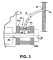
- the fixation of the discharge tube 9 to the cylinder head 8 occurs through the mounting region of one of the screws 8a used for affixing the cylinder head 8 to the cylinder block 10, which affixes, to said cylinder head 8, a discharge connector 40 which receives and secures the inlet end 9a of the discharge tube 9.
- the discharge connector 40 insulates, electrically, the discharge tube 9 from the cylinder head 8 and comprises a tubular body 41, having a first end seated against the cylinder head 8 so as to have its interior maintained in fluid communication with the orifice 8b of the cylinder head 8, and a second end, against which is seated the head of said screw 8a, which is axially loosely disposed through the tubular body 41 and through the orifice 8b of the cylinder head 8.
- the tubular body 41 is provided with a lateral opening 42, in which is affixed the inlet end 9a of the discharge tube 9, with the first and the second end of the tubular body 41 being electrically insulated from the adjacent parts defined by the cylinder head 8 and the head of the screw 8a, respectively.
- the tubular body 41 is cylindrical and metallic and provided with a radial opening 42.
- the electric insulation provided by the discharge connector 40 results in at least one of the parts defined by the tubular body 41 and the first and the second end of the discharge connector 40 being made of an electric insulating material.
- the electric insulation between the discharge connector 40 and particularly between the tubular body 41 and the parts defined by the cylinder head 8 and the head of the screw 8a is obtained by the provision of a washer 43a, made of an electric insulating material and provided between the first end of the tubular body 41 and a washer 43b between the second end of said tubular body 41 and the head of the screw 8a, said washers 43a and 43b being made of an electrically insulating material, such as polyester.
Landscapes
- Engineering & Computer Science (AREA)
- Mechanical Engineering (AREA)
- General Engineering & Computer Science (AREA)
- Compressor (AREA)
- Applications Or Details Of Rotary Compressors (AREA)
Claims (4)
- Compresseur hermétique du type qui comprend une coque hermétique (1) présentant une sortie de gaz (1a) et logeant un bloc cylindre (10) auquel est fixée, par l'intermédiaire de vis (8a), une culasse (8) définissant, intérieurement, une chambre de décharge de gaz, et un tube de décharge (9) présentant une extrémité d'entrée (9a) en communication de fluide avec la chambre de décharge de gaz par l'intermédiaire d'un orifice (8b) dans la culasse (8) et une extrémité opposée (9b) couplée par l'intermédiaire de la sortie de gaz (1a) de la coque hermétique (1), et comprenant en outre un connecteur de décharge (40) recevant et fixant l'extrémité d'entrée (9a) du tube de décharge (9),
caractérisé en ce que :ledit connecteur de décharge (40) est fixé à la culasse (8) par l'une des vis (8a) grâce à laquelle la culasse (8) est fixée au bloc cylindre (10), et est construit pour isoler électriquement le tube de décharge (9) de la culasse (8). - Compresseur selon la revendication 1, caractérisé en ce que le connecteur de décharge (40) comprend un corps tubulaire (41) ayant une première extrémité installée contre la culasse (8), afin d'avoir son intérieur maintenu en communication de fluide avec l'orifice (8b) de la culasse (8), et une seconde extrémité contre laquelle est installée la tête de ladite vis (8a) qui est disposée de manière axiale sans serrage à travers le corps tubulaire (41) et à travers l'orifice (8b) de la culasse (8), ledit corps tubulaire (41) étant doté d'une ouverture latérale (42) dans laquelle est fixée l'extrémité d'entrée (9a) du tube de décharge (9), avec la première et la seconde extrémité du corps tubulaire (41) qui sont électriquement isolées des pièces adjacentes définies par la culasse (8) et la tête de la vis (8a) respectivement.
- Compresseur selon la revendication 2, caractérisé en ce que l'isolation électrique entre le corps tubulaire (41) et les pièces définies par la culasse (8) et la tête de la vis (8a) est obtenue en prévoyant une rondelle (43a, 43b) réalisée avec un matériau électriquement isolant et qui est prévue entre la première extrémité du corps tubulaire (41) et la culasse (8) et entre la seconde extrémité dudit corps tubulaire (41) et la tête de la vis (8a).
- Compresseur selon la revendication 3, caractérisé en ce que les rondelles (43a et 43b) sont réalisées en polyester.
Applications Claiming Priority (3)
| Application Number | Priority Date | Filing Date | Title |
|---|---|---|---|
| BRPI0300607-7A BR0300607B1 (pt) | 2003-02-18 | 2003-02-18 | arranjo de montagem para tubo de descarga de compressor hermético. |
| BR0300607 | 2003-02-18 | ||
| PCT/BR2004/000011 WO2004074684A1 (fr) | 2003-02-18 | 2004-02-16 | Tuyau d'evacuation de compresseur hermetique |
Publications (2)
| Publication Number | Publication Date |
|---|---|
| EP1597479A1 EP1597479A1 (fr) | 2005-11-23 |
| EP1597479B1 true EP1597479B1 (fr) | 2008-09-10 |
Family
ID=36461099
Family Applications (1)
| Application Number | Title | Priority Date | Filing Date |
|---|---|---|---|
| EP04711327A Expired - Lifetime EP1597479B1 (fr) | 2003-02-18 | 2004-02-16 | Tuyau d'evacuation de compresseur hermetique |
Country Status (8)
| Country | Link |
|---|---|
| US (1) | US7396219B2 (fr) |
| EP (1) | EP1597479B1 (fr) |
| JP (1) | JP4564953B2 (fr) |
| KR (1) | KR101014770B1 (fr) |
| CN (1) | CN100447413C (fr) |
| BR (1) | BR0300607B1 (fr) |
| DE (1) | DE602004016466D1 (fr) |
| WO (1) | WO2004074684A1 (fr) |
Families Citing this family (7)
| Publication number | Priority date | Publication date | Assignee | Title |
|---|---|---|---|---|
| WO2007011247A2 (fr) * | 2005-07-22 | 2007-01-25 | Fisher & Paykel Appliances Limited | Compresseur de refrigeration presentant un conduit d'evacuation souple |
| BRPI0903956A2 (pt) * | 2009-01-09 | 2010-11-23 | Aurelio Mayorca | processo e equipamento para melhorar eficiência de compressores e refrigeradores |
| CN101871446B (zh) * | 2010-07-30 | 2012-05-23 | 思科普压缩机(天津)有限公司 | 排气连接头 |
| BR102012020725A2 (pt) * | 2012-08-17 | 2015-10-20 | Whirlpool Sa | arranjo de descarga de gás para um compressor de refrigeração |
| KR101855014B1 (ko) * | 2016-12-28 | 2018-05-04 | 엘지전자 주식회사 | 왕복동식 압축기 |
| KR101856392B1 (ko) | 2016-12-28 | 2018-05-09 | 엘지전자 주식회사 | 왕복동식 압축기 |
| PL4194695T3 (pl) | 2021-12-07 | 2024-10-28 | Arçelik Anonim Sirketi | Sprężarka hermetyczna z ulepszonym zespołem rurki wibracyjnej |
Family Cites Families (15)
| Publication number | Priority date | Publication date | Assignee | Title |
|---|---|---|---|---|
| FR60988E (fr) * | 1950-11-21 | 1955-02-21 | S E P A Soc D Expl Des Procede | Compresseur frigorifique à piston sphérique et applications mécaniques du piston sphérique |
| JPS51116406U (fr) * | 1975-03-18 | 1976-09-21 | ||
| JPS5648944Y2 (fr) * | 1976-11-25 | 1981-11-14 | ||
| DE3242858A1 (de) * | 1982-09-02 | 1984-03-08 | Sanyo Electric Co., Ltd., Moriguchi, Osaka | Hermetisch abgedichteter motorkompressor |
| JPS60222584A (ja) * | 1984-04-18 | 1985-11-07 | Hitachi Ltd | ロ−タリ式圧縮機 |
| JPS6195993U (fr) * | 1984-11-29 | 1986-06-20 | ||
| US5173034A (en) * | 1991-07-18 | 1992-12-22 | White Consolidated Industries, Inc. | Discharge muffler for refrigeration compressor |
| US5328338A (en) * | 1993-03-01 | 1994-07-12 | Sanyo Electric Co., Ltd. | Hermetically sealed electric motor compressor |
| US5431518A (en) * | 1993-10-29 | 1995-07-11 | Young; Donald M. | Polymeric combination washer and nut |
| JP3145012B2 (ja) * | 1995-07-12 | 2001-03-12 | シーケーディ株式会社 | 消音器 |
| JP3301895B2 (ja) * | 1995-09-05 | 2002-07-15 | 三洋電機株式会社 | 密閉型圧縮機 |
| BR9600527A (pt) | 1996-02-01 | 1997-12-30 | Brasil Compressores Sa | Arranjo de descarga para compressor hermético |
| JP2000234588A (ja) * | 1999-02-16 | 2000-08-29 | Matsushita Refrig Co Ltd | 密閉型電動圧縮機 |
| KR100310439B1 (ko) * | 1999-12-08 | 2001-09-28 | 이충전 | 왕복동식 밀폐형 압축기 |
| KR100310441B1 (ko) * | 1999-12-20 | 2001-09-28 | 이충전 | 밀폐형 왕복동식 압축기용 토출머플러의 차단판 |
-
2003
- 2003-02-18 BR BRPI0300607-7A patent/BR0300607B1/pt not_active IP Right Cessation
-
2004
- 2004-02-16 CN CNB200480004463XA patent/CN100447413C/zh not_active Expired - Fee Related
- 2004-02-16 EP EP04711327A patent/EP1597479B1/fr not_active Expired - Lifetime
- 2004-02-16 DE DE602004016466T patent/DE602004016466D1/de not_active Expired - Lifetime
- 2004-02-16 JP JP2006501391A patent/JP4564953B2/ja not_active Expired - Fee Related
- 2004-02-16 WO PCT/BR2004/000011 patent/WO2004074684A1/fr not_active Ceased
- 2004-02-16 US US10/543,798 patent/US7396219B2/en not_active Expired - Fee Related
- 2004-02-16 KR KR1020057014945A patent/KR101014770B1/ko not_active Expired - Fee Related
Also Published As
| Publication number | Publication date |
|---|---|
| EP1597479A1 (fr) | 2005-11-23 |
| KR20050102643A (ko) | 2005-10-26 |
| CN100447413C (zh) | 2008-12-31 |
| KR101014770B1 (ko) | 2011-02-14 |
| CN1751181A (zh) | 2006-03-22 |
| DE602004016466D1 (de) | 2008-10-23 |
| JP4564953B2 (ja) | 2010-10-20 |
| BR0300607A (pt) | 2004-11-16 |
| US20060110269A1 (en) | 2006-05-25 |
| BR0300607B1 (pt) | 2012-02-07 |
| US7396219B2 (en) | 2008-07-08 |
| JP2006518017A (ja) | 2006-08-03 |
| WO2004074684A1 (fr) | 2004-09-02 |
Similar Documents
| Publication | Publication Date | Title |
|---|---|---|
| JP3110455B2 (ja) | 密閉型圧縮機 | |
| US4784581A (en) | Compressor head and suction muffler for hermetic compressor | |
| WO1986002703A1 (fr) | Unite hermetique de moto-compresseur pour circuits refrigerants | |
| US5149254A (en) | Refrigeration compressor having a contoured piston | |
| NZ209575A (en) | Discharge muffler assembly for refrigeration compressor:two mufflers in series | |
| US20110103937A1 (en) | Discharge valve arrangement for a hermetic compressor | |
| US20020157717A1 (en) | Valve assembly of a reciprocal compressor | |
| EP1597479B1 (fr) | Tuyau d'evacuation de compresseur hermetique | |
| EP1301711B1 (fr) | Ensemble de soupapes d'aspiration et de refoulement pour compresseur hermetique de dimension reduite | |
| WO2000070223A1 (fr) | Compresseur a mouvement alternatif entraine par un moteur lineaire | |
| USRE33902E (en) | Compressor head and suction muffler for hermetic compressor | |
| KR100788423B1 (ko) | 흡입머플러 및 이를 갖는 압축기 | |
| US20040228746A1 (en) | Suction valve assembly of reciprocating compressor | |
| US6374943B1 (en) | Baffle plate of discharge muffler for hermetic reciprocating compressor | |
| US20040013550A1 (en) | Reciprocating compressor | |
| KR100314030B1 (ko) | 밀폐형 회전식 압축기의 흡입 장치 | |
| CN221525064U (zh) | 一种无油压缩机的进气阀门限制行程及降噪结构 | |
| WO1997031188A1 (fr) | Compresseur scelle commande par inverseur | |
| KR100202922B1 (ko) | 밀폐형 압축기의 실린더 실링기구 | |
| KR100498372B1 (ko) | 로터리 압축기 | |
| KR101576227B1 (ko) | 밀폐형 압축기용 밸브 조립체 모듈 | |
| JPH10159736A (ja) | 密閉形圧縮機 | |
| KR100311384B1 (ko) | 밀폐형회전식압축기의압축기구부지지장치 | |
| JPH03290073A (ja) | 密閉型電動圧縮機 | |
| KR100653059B1 (ko) | 로터리 압축기 |
Legal Events
| Date | Code | Title | Description |
|---|---|---|---|
| PUAI | Public reference made under article 153(3) epc to a published international application that has entered the european phase |
Free format text: ORIGINAL CODE: 0009012 |
|
| 17P | Request for examination filed |
Effective date: 20050728 |
|
| AK | Designated contracting states |
Kind code of ref document: A1 Designated state(s): AT BE BG CH CY CZ DE DK EE ES FI FR GB GR HU IE IT LI LU MC NL PT RO SE SI SK TR |
|
| AX | Request for extension of the european patent |
Extension state: AL LT LV MK |
|
| DAX | Request for extension of the european patent (deleted) | ||
| RBV | Designated contracting states (corrected) |
Designated state(s): DE IT |
|
| RAP1 | Party data changed (applicant data changed or rights of an application transferred) |
Owner name: WHIRLPOOL S.A. |
|
| 17Q | First examination report despatched |
Effective date: 20060912 |
|
| 17Q | First examination report despatched |
Effective date: 20060912 |
|
| GRAP | Despatch of communication of intention to grant a patent |
Free format text: ORIGINAL CODE: EPIDOSNIGR1 |
|
| GRAS | Grant fee paid |
Free format text: ORIGINAL CODE: EPIDOSNIGR3 |
|
| GRAA | (expected) grant |
Free format text: ORIGINAL CODE: 0009210 |
|
| AK | Designated contracting states |
Kind code of ref document: B1 Designated state(s): DE IT |
|
| REF | Corresponds to: |
Ref document number: 602004016466 Country of ref document: DE Date of ref document: 20081023 Kind code of ref document: P |
|
| PLBE | No opposition filed within time limit |
Free format text: ORIGINAL CODE: 0009261 |
|
| STAA | Information on the status of an ep patent application or granted ep patent |
Free format text: STATUS: NO OPPOSITION FILED WITHIN TIME LIMIT |
|
| 26N | No opposition filed |
Effective date: 20090611 |
|
| PGFP | Annual fee paid to national office [announced via postgrant information from national office to epo] |
Ref country code: DE Payment date: 20150227 Year of fee payment: 12 Ref country code: IT Payment date: 20150220 Year of fee payment: 12 |
|
| REG | Reference to a national code |
Ref country code: DE Ref legal event code: R119 Ref document number: 602004016466 Country of ref document: DE |
|
| PG25 | Lapsed in a contracting state [announced via postgrant information from national office to epo] |
Ref country code: IT Free format text: LAPSE BECAUSE OF NON-PAYMENT OF DUE FEES Effective date: 20160216 |
|
| PG25 | Lapsed in a contracting state [announced via postgrant information from national office to epo] |
Ref country code: DE Free format text: LAPSE BECAUSE OF NON-PAYMENT OF DUE FEES Effective date: 20160901 |