EP1597451B1 - Vorreiberverschluss - Google Patents
Vorreiberverschluss Download PDFInfo
- Publication number
- EP1597451B1 EP1597451B1 EP04710823A EP04710823A EP1597451B1 EP 1597451 B1 EP1597451 B1 EP 1597451B1 EP 04710823 A EP04710823 A EP 04710823A EP 04710823 A EP04710823 A EP 04710823A EP 1597451 B1 EP1597451 B1 EP 1597451B1
- Authority
- EP
- European Patent Office
- Prior art keywords
- housing
- actuating mechanism
- door
- lock according
- inner seal
- Prior art date
- Legal status (The legal status is an assumption and is not a legal conclusion. Google has not performed a legal analysis and makes no representation as to the accuracy of the status listed.)
- Expired - Lifetime
Links
- 238000007789 sealing Methods 0.000 claims description 9
- 238000004519 manufacturing process Methods 0.000 claims description 7
- 239000000463 material Substances 0.000 claims description 3
- HCHKCACWOHOZIP-UHFFFAOYSA-N Zinc Chemical compound [Zn] HCHKCACWOHOZIP-UHFFFAOYSA-N 0.000 claims description 2
- 230000015572 biosynthetic process Effects 0.000 claims description 2
- 239000011701 zinc Substances 0.000 claims description 2
- 229910052725 zinc Inorganic materials 0.000 claims description 2
- 238000007765 extrusion coating Methods 0.000 claims 1
- 238000005507 spraying Methods 0.000 claims 1
- 238000002347 injection Methods 0.000 description 3
- 239000007924 injection Substances 0.000 description 3
- 229910001229 Pot metal Inorganic materials 0.000 description 2
- 238000009434 installation Methods 0.000 description 2
- 238000000034 method Methods 0.000 description 2
- 239000003566 sealing material Substances 0.000 description 2
- 238000000576 coating method Methods 0.000 description 1
- 230000001419 dependent effect Effects 0.000 description 1
- 238000004512 die casting Methods 0.000 description 1
- 238000006073 displacement reaction Methods 0.000 description 1
- 230000000694 effects Effects 0.000 description 1
- 238000005538 encapsulation Methods 0.000 description 1
- 238000001746 injection moulding Methods 0.000 description 1
- 238000003754 machining Methods 0.000 description 1
- 238000012986 modification Methods 0.000 description 1
- 230000004048 modification Effects 0.000 description 1
- 238000000465 moulding Methods 0.000 description 1
- 239000003973 paint Substances 0.000 description 1
- 230000002093 peripheral effect Effects 0.000 description 1
- 239000000565 sealant Substances 0.000 description 1
- 238000007493 shaping process Methods 0.000 description 1
- 239000000243 solution Substances 0.000 description 1
- 238000011179 visual inspection Methods 0.000 description 1
Images


Classifications
-
- E—FIXED CONSTRUCTIONS
- E05—LOCKS; KEYS; WINDOW OR DOOR FITTINGS; SAFES
- E05B—LOCKS; ACCESSORIES THEREFOR; HANDCUFFS
- E05B17/00—Accessories in connection with locks
- E05B17/0004—Lock assembling or manufacturing
-
- E—FIXED CONSTRUCTIONS
- E05—LOCKS; KEYS; WINDOW OR DOOR FITTINGS; SAFES
- E05C—BOLTS OR FASTENING DEVICES FOR WINGS, SPECIALLY FOR DOORS OR WINDOWS
- E05C3/00—Fastening devices with bolts moving pivotally or rotatively
- E05C3/02—Fastening devices with bolts moving pivotally or rotatively without latching action
- E05C3/04—Fastening devices with bolts moving pivotally or rotatively without latching action with operating handle or equivalent member rigid with the bolt
- E05C3/041—Fastening devices with bolts moving pivotally or rotatively without latching action with operating handle or equivalent member rigid with the bolt rotating about an axis perpendicular to the surface on which the fastener is mounted
- E05C3/042—Fastening devices with bolts moving pivotally or rotatively without latching action with operating handle or equivalent member rigid with the bolt rotating about an axis perpendicular to the surface on which the fastener is mounted the handle being at one side, the bolt at the other side or inside the wing
-
- E—FIXED CONSTRUCTIONS
- E05—LOCKS; KEYS; WINDOW OR DOOR FITTINGS; SAFES
- E05B—LOCKS; ACCESSORIES THEREFOR; HANDCUFFS
- E05B17/00—Accessories in connection with locks
- E05B17/002—Weather or dirt protection
-
- Y—GENERAL TAGGING OF NEW TECHNOLOGICAL DEVELOPMENTS; GENERAL TAGGING OF CROSS-SECTIONAL TECHNOLOGIES SPANNING OVER SEVERAL SECTIONS OF THE IPC; TECHNICAL SUBJECTS COVERED BY FORMER USPC CROSS-REFERENCE ART COLLECTIONS [XRACs] AND DIGESTS
- Y10—TECHNICAL SUBJECTS COVERED BY FORMER USPC
- Y10S—TECHNICAL SUBJECTS COVERED BY FORMER USPC CROSS-REFERENCE ART COLLECTIONS [XRACs] AND DIGESTS
- Y10S292/00—Closure fasteners
- Y10S292/53—Mounting and attachment
-
- Y—GENERAL TAGGING OF NEW TECHNOLOGICAL DEVELOPMENTS; GENERAL TAGGING OF CROSS-SECTIONAL TECHNOLOGIES SPANNING OVER SEVERAL SECTIONS OF THE IPC; TECHNICAL SUBJECTS COVERED BY FORMER USPC CROSS-REFERENCE ART COLLECTIONS [XRACs] AND DIGESTS
- Y10—TECHNICAL SUBJECTS COVERED BY FORMER USPC
- Y10S—TECHNICAL SUBJECTS COVERED BY FORMER USPC CROSS-REFERENCE ART COLLECTIONS [XRACs] AND DIGESTS
- Y10S292/00—Closure fasteners
- Y10S292/64—Assembly
-
- Y—GENERAL TAGGING OF NEW TECHNOLOGICAL DEVELOPMENTS; GENERAL TAGGING OF CROSS-SECTIONAL TECHNOLOGIES SPANNING OVER SEVERAL SECTIONS OF THE IPC; TECHNICAL SUBJECTS COVERED BY FORMER USPC CROSS-REFERENCE ART COLLECTIONS [XRACs] AND DIGESTS
- Y10—TECHNICAL SUBJECTS COVERED BY FORMER USPC
- Y10T—TECHNICAL SUBJECTS COVERED BY FORMER US CLASSIFICATION
- Y10T292/00—Closure fasteners
- Y10T292/08—Bolts
- Y10T292/1043—Swinging
- Y10T292/1075—Operating means
- Y10T292/1083—Rigid
-
- Y—GENERAL TAGGING OF NEW TECHNOLOGICAL DEVELOPMENTS; GENERAL TAGGING OF CROSS-SECTIONAL TECHNOLOGIES SPANNING OVER SEVERAL SECTIONS OF THE IPC; TECHNICAL SUBJECTS COVERED BY FORMER USPC CROSS-REFERENCE ART COLLECTIONS [XRACs] AND DIGESTS
- Y10—TECHNICAL SUBJECTS COVERED BY FORMER USPC
- Y10T—TECHNICAL SUBJECTS COVERED BY FORMER US CLASSIFICATION
- Y10T70/00—Locks
- Y10T70/50—Special application
- Y10T70/5093—For closures
- Y10T70/5097—Cabinet
-
- Y—GENERAL TAGGING OF NEW TECHNOLOGICAL DEVELOPMENTS; GENERAL TAGGING OF CROSS-SECTIONAL TECHNOLOGIES SPANNING OVER SEVERAL SECTIONS OF THE IPC; TECHNICAL SUBJECTS COVERED BY FORMER USPC CROSS-REFERENCE ART COLLECTIONS [XRACs] AND DIGESTS
- Y10—TECHNICAL SUBJECTS COVERED BY FORMER USPC
- Y10T—TECHNICAL SUBJECTS COVERED BY FORMER US CLASSIFICATION
- Y10T70/00—Locks
- Y10T70/50—Special application
- Y10T70/5093—For closures
- Y10T70/5155—Door
- Y10T70/5199—Swinging door
- Y10T70/5246—Dead bolts
- Y10T70/5296—Single
- Y10T70/5345—Swinging
- Y10T70/5363—Key operable only
-
- Y—GENERAL TAGGING OF NEW TECHNOLOGICAL DEVELOPMENTS; GENERAL TAGGING OF CROSS-SECTIONAL TECHNOLOGIES SPANNING OVER SEVERAL SECTIONS OF THE IPC; TECHNICAL SUBJECTS COVERED BY FORMER USPC CROSS-REFERENCE ART COLLECTIONS [XRACs] AND DIGESTS
- Y10—TECHNICAL SUBJECTS COVERED BY FORMER USPC
- Y10T—TECHNICAL SUBJECTS COVERED BY FORMER US CLASSIFICATION
- Y10T70/00—Locks
- Y10T70/70—Operating mechanism
- Y10T70/7441—Key
- Y10T70/7486—Single key
- Y10T70/7508—Tumbler type
- Y10T70/7559—Cylinder type
- Y10T70/7667—Operating elements, parts and adjuncts
- Y10T70/7672—Cylinder
-
- Y—GENERAL TAGGING OF NEW TECHNOLOGICAL DEVELOPMENTS; GENERAL TAGGING OF CROSS-SECTIONAL TECHNOLOGIES SPANNING OVER SEVERAL SECTIONS OF THE IPC; TECHNICAL SUBJECTS COVERED BY FORMER USPC CROSS-REFERENCE ART COLLECTIONS [XRACs] AND DIGESTS
- Y10—TECHNICAL SUBJECTS COVERED BY FORMER USPC
- Y10T—TECHNICAL SUBJECTS COVERED BY FORMER US CLASSIFICATION
- Y10T70/00—Locks
- Y10T70/70—Operating mechanism
- Y10T70/7441—Key
- Y10T70/7486—Single key
- Y10T70/7508—Tumbler type
- Y10T70/7559—Cylinder type
- Y10T70/7667—Operating elements, parts and adjuncts
- Y10T70/7684—Plug
-
- Y—GENERAL TAGGING OF NEW TECHNOLOGICAL DEVELOPMENTS; GENERAL TAGGING OF CROSS-SECTIONAL TECHNOLOGIES SPANNING OVER SEVERAL SECTIONS OF THE IPC; TECHNICAL SUBJECTS COVERED BY FORMER USPC CROSS-REFERENCE ART COLLECTIONS [XRACs] AND DIGESTS
- Y10—TECHNICAL SUBJECTS COVERED BY FORMER USPC
- Y10T—TECHNICAL SUBJECTS COVERED BY FORMER US CLASSIFICATION
- Y10T70/00—Locks
- Y10T70/70—Operating mechanism
- Y10T70/7441—Key
- Y10T70/7486—Single key
- Y10T70/7508—Tumbler type
- Y10T70/7559—Cylinder type
- Y10T70/7667—Operating elements, parts and adjuncts
- Y10T70/7706—Operating connections
Definitions
- the invention relates to a cam lock, in particular for use on a thin-walled door, in particular of cabinets, with a door through the associated opening and fixed to the door by means of a housing head supported thereon housing, a rotatably disposed inside the housing actuation and a with the operation associated locking tongue, wherein the sash closure associated with an assembly on the door between the housing head and the door outer seal for radial sealing of the door opening and disposed inside the housing an inner seal for sealing the operation against the housing, wherein the locking tongue and actuation are integrally formed with each other and the actuator and the housing enclosing the actuation are captively connected to each other, wherein the inner seal in at least one formed on the actuator Freirau m comes to rest.
- cam lock is known from WO 91 14 845 A, which corresponds to the preamble of claim 1.
- the rotor housing is first to be mounted on the underside of the housing head during assembly and thus the radial seal of the door breakthrough against the sash closure accepting outer seal required, inside the housing in addition to the sealing of the housing against the rotatable operation inside an inner seal is inserted.
- cam lock has the disadvantage that the individual components of the cam lock such as housing, actuation, locking tongue, fixing screw and inner seal and outer seal must be made in each case independent production steps and kept in stock, and that it is for producing a single cam lock a separate assembly of requires several individual parts with each other.
- the invention is therefore an object of the invention to provide a VorreiberverschluB with the features mentioned above available, which is simple and thus can be produced at low cost.
- the invention provides in its basic idea that the inner seal located between the housing and actuation is formed by injection molding to the housing. Due to the one-piece design of actuation and locking tongue only the housing to be produced in addition to the component thus formed, in particular, the inner seal molded in the so-called two-K method to the housing and thus becomes an integral part of the cam lock.
- inventively provided captive connection of housing and the actuator and locking tongue component is advantageously ensured that the locking tongue is not on the operation can be solved so that the Verschlul3funktion the cam lock is constantly given in cooperation with the housing.
- the sealing of the housing against the operation serving inner seal is formed integrally with the sealing of the housing serving against the door, arranged on the underside of the housing head outer seal and for connecting the outer seal and inner seal to the Housing are formed in the longitudinal direction extending channels for receiving molded connection strands, this results in the particular advantage that in addition to the production of the inner seal and the outer seal is integrated into the cam lock, so that a high degree of protection is ensured when using the inventively designed cam lock ,
- the captive connection of the housing and actuation is made at the same time producing the housing by encapsulation of the actuator. This results in the particular advantage of saving a further manufacturing or assembly step.
- actuation and housing are positively connected to each other and the actuator in its enclosed by the housing portion a radial constriction and the housing have an engaging in the constriction of the operation paragraph and that for the formation of the free space, the longitudinal extension of the constriction of the operation is dimensioned larger than the longitudinal extent of the shoulder of the housing, wherein the inner seal between actuation and housing in each case by the housing head facing edge of constriction and paragraph limited space can be injected.
- the captive connection of housing and actuation can be made by clipping the two components to be connected.
- the set up for the attack of a tool head of the actuator is made of die-cast zinc; by this measure, the resistance of the operation is increased when interacting with an opening tool, wherein the further base body of the actuator is formed integrally with the locking tongue and molded onto the zinc die casting head of the actuator.
- the housing is provided on its adjoining the housing head outside with a split into two threaded sections male thread and the oppositely disposed male thread sections are separated by two respective planar surfaces and one with a corresponding adapted design trained union nut with their flat sections to the plant on the Door back to the housing attachable and then rotatable by an angular amount, wherein the formed on the flat surfaces of the union nut female threaded portions come into engagement with the male threaded portions of the housing.
- the threads of the thread formed on the union nut and / or on the housing are provided with radially projecting and engaging in the opposite thread locking teeth.
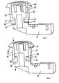
- the actuator 10 and locking tongue 11 are formed as a one-piece component, said component being made of any material can. It may prove expedient if the head 30 of the actuator 10 is made of die-cast zinc, while the rest of the body of the actuator 10 including the locking tongue 11 is made of plastic and molded onto the head 30 of the actuator.
- the actuator 10 is provided with a circumferential constriction 12 which has a smaller axial longitudinal extent above the connected locking tongue 11 than on the remaining circumference of the actuator 10.
- the housing 13 shown in Figure 2 has at its upper end a flange-like housing head 14, with which the housing 13 comes into contact with the door leaf during installation on a door.
- the housing 13 has an inner bore 15 for receiving the actuator, and at the lower end of the housing 13, the housing 13 has a peripheral shoulder 16, which is intended to cooperate with the constriction 12 of the actuator 10 ( Figure 1) and in so far in accordance with the shape of the constriction 12 each having a corresponding axial extent.
- FIG. 5 shows the configuration of the inner seal 18 and the outer seal 20 produced so far in one machining operation.
- the sealing material may be provided with a different color than housing and / or operation, because in this way can be checked by visual inspection, that in particular the outer seal 20 is verwirktlicht in sufficient form.
- FIGs 6 and 7 another embodiment of the cam lock is shown, which includes a quick mounting of the cam lock on a door panel, not shown, and further - in contrast to the described to Figures 1 to 5 embodiment - of a captive clip connection between actuation with locking tongue and housing emanates.
- an external thread is applied on the outside of the housing 13, which thread is divided into two externally threaded sections 21 arranged opposite each other, wherein these external thread sections 21 are separated from one another by two respective planar surfaces 22.
- the union nut 23 which can be pushed onto the housing 13 and serves for fastening, has an internal thread which likewise has two internal thread sections 25, which are now formed on the flat surfaces 24 provided on the union nut 23; the flat surfaces 24 with the internally threaded portions 25 formed thereon are connected to each other by circular arc sections 26.
- the respective planar surfaces are used for axial postponement of the union nut 23 until it rests against the rear surface of the (not shown) door panel.
- a clip connection is provided, on the housing head 14 opposite end side of the housing 13, two axially projecting clip arms 28 are arranged with radially inwardly projecting Klipsvorsprüngen 29, wherein the Klipsvorsprünge 29 in one of the actuator 10th formed rear, the locking tongue 11 adjacent groove 27 engage.
- the clip projections 29 may be formed with a corresponding chamfer. In the assembled state ( Figure 7), the clip arms 29 are held by the screwed union nut 23 in engagement with the actuator 10.
- an external toothing 31 is provided on the outside of the union nut 23, to which a suitable tool for mounting the union nut 23 can be attached.
Landscapes
- Engineering & Computer Science (AREA)
- Mechanical Engineering (AREA)
- Manufacturing & Machinery (AREA)
- Lock And Its Accessories (AREA)
- Mutual Connection Of Rods And Tubes (AREA)
- Endoscopes (AREA)
- Valve Device For Special Equipments (AREA)
Description
- Die Erfindung betrifft einen Vorreiberverschluß, insbesondere zum Einsatz an einer dünnwandigen Tür insbesondere von Schaltschränken, mit einem die Tür in einer zugeordneten Öffnung durchgreifenden und an der Tür mittels eines sich daran abstützenden Gehäusekopfes festlegbaren Gehäuse, einer im Inneren des Gehäuses drehbar angeordneten Betätigung sowie einer mit der Betätigung verbundenen Verriegelungszunge, wobei dem Vorreiberverschluß eine bei der Montage an der Tür zwischen dem Gehäusekopf und der Tür einzulegende Außendichtung zur radialen Abdichtung des Türdurchbruches zugeordnet und im Inneren des Gehäuses eine Innendichtung zur Abdichtung der Betätigung gegen das Gehäuse angeordnet ist, wobei Verriegelungszunge und Betätigung einstückig miteinander ausgebildet sind und die Betätigung und das die Betätigung umschliessende Gehäuse unverlierbar miteinander verbunden sind, wobei die Innendichtung in wenigstens einem an der Betätigung ausgebildeten Freiraum zu liegen kommt.
- Ein derartiger Vorreiberverschluss ist aus WO 91 14 845 A bekannt, der dem Oberbegriff des Anspruchs 1 entspricht.
- Ein alternativer Vorreiberverschluß ist in der DE-C2-33 16 834 beschrieben. Bei dem bekannten Vorreiberverschluß ist die Betätigung in das Gehäuse von dem auf der Türaußenseite anzuordnenden Gehäusekopf des Gehäuses her eingesetzt und stützt sich im Inneren des Gehäuses über eine entsprechend ausgebildete Schulter gegen eine weitere axiale Verschiebung im Gehäuse ab; auf einen über das Gehäuse innenseitig überragenden Ansatz der Betätigung ist in formschlüssiger Verbindung damit eine Verriegelungszunge aufgesetzt und an der Betätigung durch eine axial in die Betätigung eingeschraubte Schraube befestigt. Zusätzlich ist zwischen Gehäuse und Betätigung noch eine Wellscheibe unter anderem zum Toleranzausgleich angeordnet. Zur Abdichtung des Vorreibergehäuses ist zunächst eine an der Unterseite des Gehäusekopfes bei der Montage anzubringende und damit die radiale Abdichtung des Türdurchbruchs gegen den Vorreiberverschluß übernehmende Außendichtung erforderlich, wobei im Inneren des Gehäuses zusätzlich zur Abdichtung des Gehäuses gegen die darin drehbare Betätigung eine Innendichtung eingelegt ist.
- Mit dem bekannten Vorreiberverschluß ist der Nachteil verbunden, daß die einzelnen Bauteile des Vorreiberverschlusses wie Gehäuse, Betätigung, Verriegelungszunge, Befestigungsschraube sowie Innendichtung und Außendichtung in jeweils eigenständigen Produktionsschritten hergestellt und vorrätig gehalten werden müssen, und daß es zur Herstellung eines einzelnen Vorreiberverschlusses einer gesonderten Montage der mehreren Einzelteile miteinander bedarf.
- Der Erfindung liegt daher die Aufgabe zugrunde, einen VorreiberverschluB mit den eingangs genannten Merkmalen zur Verfügung zu stellen, der einfach und damit zu geringen Kosten herstellbar ist.
- Die Lösung dieser Aufgabe ergibt sich aus dem Inhalt des Hauptanspruches. Vorteilhafte Ausgestaltungen und Weiterbildungen der Erfindung ergeben sich aus dem Inhalt der abhängigen Patentansprüche.
- Die Erfindung sieht in ihrem Grundgedanken vor, daß die zwischen Gehäuse und Betätigung befindliche Innendichtung durch Anspritzen an das Gehäuse gebildet ist. Aufgrund der einstückigen Ausbildung von Betätigung und Verriegelungszunge ist neben dem so gebildeten Bauteil nur noch das Gehäuse herzustellen, wobei insbesondere die Innendichtung im sogenannten Zwei-K-Verfahren an das Gehäuse angespritzt und damit integraler Bestandteil des Vorreiberverschlusses wird. Durch die erfindungsgemäß vorgesehene unverlierbare Verbindung von Gehäuse und dem aus Betätigung und Verriegelungszunge bestehenden Bauteil ist in vorteilhafter Weise sichergestellt, daß die Verriegelungszunge nicht von der Betätigung gelöst werden kann, so daß im Zusammenwirken mit dem Gehäuse die Verschlul3funktion des Vorreiberverschlusses ständig gegeben ist.
- Soweit nach einem Ausführungsbeispiel der Erfindung vorgesehen ist, daß die der Abdichtung des Gehäuses gegen die Betätigung dienende Innendichtung einstückig mit der der Abdichtung des Gehäuses gegen die Tür dienenden, an der Unterseite des Gehäusekopfes angeordneten Außendichtung ausgebildet ist und zur Verbindung von Außendichtung und Innendichtung an dem Gehäuse sich in dessen Längsrichtung erstreckende Kanäle zur Aufnahme von angespritzten Verbindungssträngen ausgebildet sind, ergibt sich daraus der besondere Vorteil, daß neben der Herstellung der Innendichtung auch die Außendichtung in den Vorreiberverschluß integriert ist, so daß eine hohe Schutzart beim Einsatz des erfindungsgemäß ausgestalteten Vorreiberverschlusses gewährleistet ist.
- Nach einem zweckmäßigen Ausführungsbeispiel der Erfindung ist vorgesehen, daß die unverlierbare Verbindung von Gehäuse und Betätigung bei gleichzeitiger Herstellung des Gehäuses durch Umspritzen der Betätigung hergestellt ist. Hierbei ergibt sich der besondere Vorteil der Einsparung eines weiteren Fertigungs- bzw. Montageschrittes.
- Nach einem Ausführungsbeispiel der Erfindung ist dabei vorgesehen, daß Betätigung und Gehäuse formschlüssig miteinander verbunden sind und die Betätigung in ihrem von dem Gehäuse umschlossenen Abschnitt eine radiale Einschnürung und das Gehäuse einen in die Einschnürung der Betätigung eingreifenden Absatz aufweisen und daß zur Ausbildung des Freiraumes die Längserstreckung der Einschnürung der Betätigung größer bemessen ist als die Längserstreckung des Absatzes des Gehäuses, wobei die Innendichtung zwischen Betätigung und Gehäuse in den jeweils durch den dem Gehäusekopf zugewandten Rand von Einschnürung und Absatz begrenzten Freiraum eingespritzt sein kann.
- Alternativ kann die unverlierbare Verbindung von Gehäuse und Betätigung durch Klipsen der beiden zu verbindenden Bauteile hergestellt sein.
- Nach einem Ausführungsbeispiel der Erfindung ist vorgesehen, daß der zum Angriff eines Werkzeuges eingerichtete Kopf der Betätigung aus Zinkdruckguß besteht; durch diese Maßnahme wird die Widerstandsfähigkeit der Betätigung beim Zusammenwirken mit einem Öffnungswerkzeug erhöht, wobei der weitere Grundkörper der Betätigung gemeinsam mit der Verriegelungszunge einstückig ausgebildet und an den aus Zinkdruckguß bestehenden Kopf der Betätigung angespritzt ist.
- Zur Ausbildung einer Schnellbefestigung ist nach einem Ausführungsbeispiel der Erfindung vorgesehen, daß das Gehäuse auf seiner an dem Gehäusekopf anschließenden Außenseite mit einem in zwei Gewindeabschnitte aufgeteilten Außengewinde versehen ist und die einander gegenüberliegend angeordneten Außengewindeabschnitte durch zwei jeweils plane Flächen voneinander getrennt sind und daß eine mit einer entsprechenden angepaßten Formgebung ausgebildete Überwurfmutter mit ihren planen Abschnitten bis zur Anlage an der Türrückseite auf das Gehäuse aufsteckbar und danach um einen Winkelbetrag drehbar ist, wobei die an den planen Flächen der Überwurfmutter ausgebildeten Innengewindeabschnitte mit den Außengewindeabschnitten des Gehäuses in Eingriff kommen.
- Soweit die unverlierbare Verbindung von Gehäuse und Betätigung durch Klipsen vorgesehen ist, ist nach einem Ausführungsbeispiel der Erfindung vorgesehen, daß an der dem Gehäusekopf gegenüberliegenden Stirnseite des Gehäuses zwei axial vorstehende Klipsarme mit in einer an der Betätigung ausgebildeten hinteren Nut eingreifenden Klipsvorsprüngen angeordnet sind, wobei die Klipsarme durch die aufgeschraubte Überwurfmutter in Eingriff mit der Betätigung gehalten sein können.
- Schließlich ist nach einem Ausführungsbeispiel der Erfindung vorgesehen, daß die Gewindegänge des an der Überwurfmutter und/oder am Gehäuse ausgebildeten Gewindes mit radial abstehenden und in den gegenüberliegenden Gewindegang eingreifenden Rastzähnen versehen sind. Mit dieser Maßnahme können Temperaturschwankungen, Lackungen, Lackunebenheiten auf dem Türblech oder dynamische Schwingungseinflüsse der Umgebung neutralisiert werden, so daß ein selbsttätiges Lösen der Überwurfmutter von dem Gehäuse ausgeschlossen werden kann.
- In der Zeichnung sind Ausführungsbeispiele der Erfindung wiedergegeben, welche nachstehend beschrieben sind. Es zeigen:
- Fig. 1
- das aus Betätigung und Verriegelungszunge bestehende Bauteil in einer geschnittenen Seitenansicht,
- Fig. 2
- das Gehäuse des Vorreiberverschlusses in einer ersten Ausführungsform in einer geschnittenen Seitenansicht,
- Fig. 3
- den Vorreiberverschluß mit zusammengefügten Einzelteilen gemäß Figuren 1 und 2 in geschnittener Seitenansicht vor Einspritzen der Dichtung,
- Fig. 4
- den Gegenstand der Figur 3 nach Einspritzen der Dichtung,
- Fig. 5
- den aus Innendichtung und Außendichtung bestehenden Dichtungskörper in einer isolierten schaubildlichen Darstellung,
- Fig. 6
- ein anderes Ausführungsbeispiel eines aus Gehäuse, Betätigung mit Verriegelungszunge und Überwurfmutter bestehenden Vorreiberverschlusses in einer auseinandergezogenen Darstellung,
- Fig. 7
- den Gegenstand der Figur 6 in zusammenmontiertem Zustand.
- Wie sich zunächst aus Figur 1 ergibt, sind Betätigung 10 und Verriegelungszunge 11 als ein einstückiges Bauteil ausgebildet, wobei dieses Bauteil aus einem beliebigen Material hergestellt sein kann. Dabei kann es sich als zweckmäßig erweisen, wenn der Kopf 30 der Betätigung 10 aus Zinkdruckguß besteht, während der übrige Körper der Betätigung 10 einschließlich der Verriegelungszunge 11 aus Kunststoff besteht und an den Kopf 30 der Betätigung angespritzt ist. Die Betätigung 10 ist mit einer umlaufenden Einschnürung 12 versehen, die oberhalb der angeschlossenen Verriegelungszunge 11 eine geringere axiale Längserstreckung aufweist als auf dem übrigen Umfang der Betätigung 10.
- Das in Figur 2 dargestellte Gehäuse 13 hat an seinem oberen Ende einen flanschartigen Gehäusekopf 14, mit welchem das Gehäuse 13 bei der Montage an einer Tür in Anlage an dem Türblatt kommt. Das Gehäuse 13 hat eine Innenbohrung 15 zur Aufnahme der Betätigung, und am unteren Ende des Gehäuses 13 weist das Gehäuse 13 einen umlaufenden Absatz 16 auf, der zum Zusammenwirken mit der Einschnürung 12 der Betätigung 10 (Figur 1) bestimmt ist und insoweit in Übereinstimmung mit der Gestalt der Einschnürung 12 jeweils eine entsprechende axiale Erstreckung aufweist.
- Dem in den Figuren 3 und 4 dargestellten Ausführungsbeispiel der unverlierbaren Verbindung des in Figur 1 dargestellten Bauteils mit dem in Figur 2 dargestellten Gehäuse 13 liegt ein Herstellungsverfahren zugrunde, bei welchem die Herstellung des die Betätigung 10 umschließenden Gehäuses 13 durch Umspritzen der Betätigung 10 mit einem geeigneten, spritzfähigen Material, vorzugsweise einem geeigneten Kunststoff, erfolgt. Bei diesem in Figur 3 dargestellten Spritzvorgang wird die axiale Längserstreckung des Absatzes 16 im Verhältnis zur Abmessung der Einschnürung 12 der Betätigung 10 derart bemessen, daß ein Freiraum 17 zwischen dem unteren Ende des Absatzes 16 und der benachbarten Begrenzungskante der Einschnürung 12 verbleibt. Wie aus Figur 4 ersichtlich ist, werden anschließend das Gehäuse 13 und die Betätigung 10 gegeneinander gedrückt, so daß sich das Gehäuse 13 gegenüber der Betätigung 10 axial verschiebt und der Freiraum 17 an das dem Gehäusekopf 14 zugewandte obere Ende der Einschnürung zu liegen kommt. In dieser Stellung wird der so verlagerte Freiraum mit einer Dichtungsmasse ausgespritzt, so daß sich in diesem Bereich die Innendichtung 18 ergibt. Da auf dem äußeren Umfang des Gehäuses 13 Kanäle 19 ausgebildet sind, die sich von der Innendichtung 18 bis an die Unterseite des Gehäusekopfes 14 erstrecken, fließt das in den Freiraum 17 eingespritzte Dichtungsmaterial über die Kanäle 19 in den Bereich des Gehäusekopfes 14 und bildet hier bei entsprechender Formgebung der zugeordneten Form gleichzeitig die Außendichtung 20 aus.
- Aus Figur 5 ist die Konfiguration der insoweit in einem Bearbeitungsgang hergestellten Innendichtung 18 und Außendichtung 20 zu erkennen.
- Im Rahmen eines solchen Herstellungsvorganges kann es zweckmäßig sein, das Dichtungsmaterial mit einer anderen Farbgebung als Gehäuse und/oder Betätigung zu versehen, weil auf diese Weise durch Inaugenscheinnahme geprüft werden kann, daß insbesondere die Außendichtung 20 in ausreichender Form verwirktlicht ist.
- In den Figuren 6 und 7 ist ein anderes Ausführungsbeispiel des Vorreiberverschlusses dargestellt, welches eine Schnellbefestigung des Vorreiberverschlusses an einem nicht dargestellten Türblatt einschließt und weiterhin - im Unterschied zu dem zu Figuren 1 bis 5 beschriebenen Ausführungsbeispiel - von einer unverlierbaren Klipsverbindung zwischen Betätigung mit Verriegelungszunge und Gehäuse ausgeht.
- Wie zunächst aus Figur 6 zu entnehmen ist, ist auf der Außenseite des Gehäuses 13 ein Außengewinde aufgebracht, welches in zwei einander gegenüberliegend angeordnete Außengewindeabschnitte 21 unterteilt ist, wobei diese Außengewindeabschnitte 21 durch zwei jeweils plane Flächen 22 voneinander getrennt sind. In einer entsprechenden Formgebung weist die auf das Gehäuse 13 aufschiebbare und zur Befestigung dienende Überwurfmutter 23 ein Innengewinde auf, welches ebenfalls zwei Innengewindeabschnitte 25 aufweist, die nunmehr an den an der Überwurfmutter 23 vorhandenen planen Flächen 24 ausgebildet sind; die planen Flächen 24 mit den daran ausgebildeten Innengewindeabschnitten 25 sind durch Kreisbogenabschnitte 26 miteinander verbunden. Die jeweils planen Flächen dienen zum axialen Aufschub der Überwurfmutter 23 bis zur Anlage an der rückwärtigen Fläche des (nicht dargestellten) Türbleches. Durch eine Teildrehung der Überwurfmutter 23 gegenüber dem Gehäuse 13 wird aufgrund einer entsprechend eingerichteten Gewindesteigung der Vorreiberverschluß an dem Gehäuse befestigt.
- Soweit zur unverlierbaren Verbindung von Gehäuse 13 und Betätigung 10 eine Klipsverbindung vorgesehen ist, sind an der dem Gehäusekopf 14 gegenüberliegenden Stirnseite des Gehäuses 13 zwei axial vorstehende Klipsarme 28 mit davon radial einwärts vorstehenden Klipsvorsprüngen 29 angeordnet, wobei die Klipsvorsprünge 29 in eine an der Betätigung 10 ausgebildete hintere, der Verriegelungszunge 11 benachbarte Nut 27 eingreifen. Zur besseren Montage können dabei die Klipsvorsprünge 29 mit einer entsprechenden Anschrägung ausgebildet sein. In montiertem Zustand (Figur 7) werden die Klipsarme 29 durch die aufgeschraubte Überwurfmutter 23 in Eingriff mit der Betätigung 10 gehalten.
- Auf der Außenseite der Überwurfmutter 23 ist bei dem dargestellten Ausführungsbeispiel eine Außenverzahnung 31 vorgesehen, an der ein geeignetes Werkzeug zum Montieren der Überwurfmutter 23 angesetzt werden kann.
Claims (11)
- Vorreiberverschluß, insbesondere zum Einsatz an einer dünnwandigen Tür insbesondere von Schaltschränken, mit einem die Tür in einer zugeordneten Öffnung durchgreifenden und an der Tür mittels eines sich daran abstützenden Gehäusekopfes festlegbaren Gehäuse, einer im Inneren des Gehäuses drehbar angeordneten Betätigung (10) sowie einer mit der Betätigung (10) verbundenen Verriegelungszunge (11), wobei dem Vorreiberverschluß eine bei der Montage an der Tür zwischen dem Gehäusekopf und der Tür einzulegende Außendichtung (20) zur radialen Abdichtung des Türdurchbruches zugeordnet und im Inneren des Gehäuses (13) eine Innendichtung (18) zur Abdichtung der Betätigung (10) gegen das Gehäuse (13) angeordnet ist, wobei Verriegelungszunge (11) und Betätigung (10) einstückig miteinander ausgebildet sind und die Betätigung (10) und das die Betätigung (10) umschließende Gehäuse (13) unverlierbar miteinander verbunden sind, wobei die Innendichtung (18) in wenigstens einem an der Betätigung (10) ausgebildeten Freiraum (17) zu liegen kommt dadurch gekennzeichnet, daß die zwischen Gehäuse (13) und Betätigung (10) befindliche Innendichtung (18) durch Anspritzen an das Gehäuse (13) gebildet ist.
- Vorreiberverschluß nach Anspruch 1, dadurch gekennzeichnet, daß die der Abdichtung des Gehäuses (13) gegen die Betätigung (10) dienende Innendichtung (18) einstückig mit der der Abdichtung des Gehäuses (13) gegen die Tür dienenden, an der Unterseite des Gehäusekopfes (14) angeordneten Außendichtung (20) ausgebildet ist und zur Verbindung von Außendichtung (20) und Innendichtung (18) an dem Gehäuse (13) sich in dessen Längsrichtung erstreckende Kanäle (19) zur Aufnahme von angespritzten Verbindungssträngen ausgebildet sind.
- Vorreiberverschluß nach Anspruch 1 oder 2, dadurch gekennzeichnet, daß Betätigung (10) und Gehäuse (13) formschlüssig miteinander verbunden sind und die Betätigung (10) in ihrem von dem Gehäuse (13) umschlossenen Abschnitt eine radiale Einschnürung (12) und das Gehäuse (13) einen in die Einschnürung (12) der Betätigung (10) eingreifenden Absatz (16) aufweisen und daß zur Bildung des der Ausbildung der Innendichtung (18) dienenden Freiraumes (17) die Längserstreckung der Einschnürung (12) der Betätigung (10) größer bemessen ist als die Längserstreckung des Absatzes (16) des Gehäuses (13).
- Vorreiberverschluß nach einem der Ansprüche 1 bis 3, dadurch gekennzeichnet, daß die unverlierbare Verbindung von Gehäuse (13) und Betätigung (10) bei gleichzeitiger Herstellung des Gehäuses (13) durch Umspritzen der Betätigung (10) hergestellt ist.
- Vorreiberverschluß nach Anspruch 4, dadurch gekennzeichnet, daß die Innendichtung (18) zwischen Betätigung (10) und Gehäuse (13) in den jeweils durch den dem Gehäusekopf (14) zugewandten Rand von Einschnürung (12) und Absatz (16) begrenzten Freiraum (17) eingespritzt ist.
- Vorreiberverschluß nach einem der Ansprüche 1 bis 3, dadurch gekennzeichnet, daß die unverlierbare Verbindung von Gehäuse (13) und Betätigung (10) durch Klipsen hergestellt ist.
- Vorreiberverschluß nach einem der Ansprüche 1 bis 6, dadurch gekennzeichnet, daß der zum Angriff eines Werkzeuges eingerichtete Kopf (30) der Betätigung (10) aus Zinkdruckguß besteht.
- Vorreiberverschluß nach einem der Ansprüche 1 bis 7, dadurch gekennzeichnet, daß das Gehäuse (13) auf seiner an dem Gehäusekopf (14) anschließenden Außenseite mit einem in zwei Gewindeabschnitte (21) aufgeteilten Außengewinde versehen ist und die einander gegenüberliegend angeordneten Außengewindeabschnitte (21) durch zwei jeweils plane Flächen (22) voneinander getrennt sind und daß eine mit einer entsprechenden angepaßten Formgebung ausgebildete Überwurfmutter (23) mit ihren planen Abschnitten (24) bis zur Anlage an der Türrückseite auf das Gehäuse (13) aufsteckbar und danach um einen Winkelbetrag drehbar ist, wobei die an den planen Flächen (24) der Überwurfmutter (23) ausgebildeten Innengewindeabschnitte (25) mit den Außengewindeabschnitten (21) des Gehäuses (13) in Eingriff kommen.
- Vorreiberverschluß nach einem der Ansprüche 1 bis 10, dadurch gekennzeichnet, daß an der dem Gehäusekopf (14) gegenüberliegenden Stirnseite des Gehäuses (13) zwei axial vorstehende Klipsarme (28) mit in einer an der Betätigung (10) ausgebildeten hinteren Nut (27) eingreifenden Klipsvorsprüngen (29) angeordnet sind.
- Vorreiberverschluß nach Anspruch 8 und 9, dadurch gekennzeichnet, daß die Klipsarme (28) durch die aufgeschraubte Überwurfmutter (23) in Eingriff mit der Betätigung (10) gehalten sind.
- Vorreiberverschluß nach einem der Ansprüche 8 bis 10, dadurch gekennzeichnet, daß die Gewindegänge des an der Überwurfmutter (23) und/oder am Gehäuse (13) ausgebildeten Gewindes mit radial abstehenden und in den gegenüberliegenden Gewindegang eingreifenden Rastzähnen versehen sind.
Applications Claiming Priority (3)
| Application Number | Priority Date | Filing Date | Title |
|---|---|---|---|
| DE20303200U | 2003-02-26 | ||
| DE20303200U DE20303200U1 (de) | 2003-02-26 | 2003-02-26 | Vorreiberverschluß |
| PCT/EP2004/001394 WO2004076787A1 (de) | 2003-02-26 | 2004-02-13 | Vorreiberverschluss |
Publications (2)
| Publication Number | Publication Date |
|---|---|
| EP1597451A1 EP1597451A1 (de) | 2005-11-23 |
| EP1597451B1 true EP1597451B1 (de) | 2007-05-16 |
Family
ID=7980408
Family Applications (1)
| Application Number | Title | Priority Date | Filing Date |
|---|---|---|---|
| EP04710823A Expired - Lifetime EP1597451B1 (de) | 2003-02-26 | 2004-02-13 | Vorreiberverschluss |
Country Status (6)
| Country | Link |
|---|---|
| US (1) | US7350382B2 (de) |
| EP (1) | EP1597451B1 (de) |
| AT (1) | ATE362573T1 (de) |
| DE (2) | DE20303200U1 (de) |
| ES (1) | ES2286607T3 (de) |
| WO (1) | WO2004076787A1 (de) |
Families Citing this family (6)
| Publication number | Priority date | Publication date | Assignee | Title |
|---|---|---|---|---|
| DE102005061231B4 (de) * | 2005-12-20 | 2020-04-09 | Huf Hülsbeck & Fürst Gmbh & Co. Kg | Zylinderkern |
| ES2343936B1 (es) * | 2008-12-23 | 2011-06-16 | Ojmar, S.A. | Cerradura de pomo bloqueable. |
| US9377037B2 (en) * | 2013-03-15 | 2016-06-28 | Ron R. Daniels | Lock device and method of use |
| WO2018169687A1 (en) * | 2017-03-16 | 2018-09-20 | ASSA ABLOY Residential Group, Inc. | Gasket system for an electromechanical lock |
| DE102018119140A1 (de) * | 2018-08-07 | 2020-02-13 | Otto Ganter Gmbh & Co. Kg Normteilefabrik | Abgedichteter Verriegelungsbeschlag |
| US20220282535A1 (en) * | 2019-08-13 | 2022-09-08 | Ron Zeitler | Quarter turn twist lock door latch |
Family Cites Families (18)
| Publication number | Priority date | Publication date | Assignee | Title |
|---|---|---|---|---|
| US3303678A (en) * | 1964-11-23 | 1967-02-14 | Chrysler Corp | Pin tumbler lock cylinder assembly |
| US3465557A (en) * | 1967-11-15 | 1969-09-09 | Illinois Tool Works | Freezer lock assembly |
| FR2429310A1 (fr) * | 1978-06-21 | 1980-01-18 | Telemecanique Electrique | Dispositif de fermeture pour porte ou analogue |
| GB2042048B (en) * | 1979-01-26 | 1982-11-24 | Unimax Switch Ltd | Keyoperated device |
| IT1127745B (it) * | 1979-12-18 | 1986-05-21 | Itw Fastex Italia Spa | Tappo con serratura inseribile a fondo linea per bocchettoni di serbatoi di carburante di autoveicoli |
| FR2514060A1 (fr) * | 1981-10-06 | 1983-04-08 | Telemecanique Electrique | Serrure a fermeture automatique par clenche pivotante |
| DE3316834C3 (de) | 1983-05-07 | 1997-11-13 | Dieter Ramsauer | Betätigungsdorn zur Lagerung in einem Verschlußgehäuse für einen Türverschluß für einen Schaltschrank |
| US4910982A (en) | 1988-10-14 | 1990-03-27 | Engineered Security Products Corporation | Self-assembling locking device |
| DE9003554U1 (de) | 1990-03-27 | 1991-08-01 | Emka Beschlagteile GmbH & Co. KG, 5620 Velbert | Drehriegelverschluß mit einstellbarem Abstand zwischen Drehriegel und Gehäuse |
| FR2682147B1 (fr) * | 1991-10-04 | 1993-11-26 | Merlin Gerin | Dispositif de retenue d'une cle d'une serrure. |
| US5413392A (en) * | 1993-04-06 | 1995-05-09 | Southco, Inc. | Pawl assembly |
| CA2146307C (en) * | 1994-04-05 | 2005-07-05 | David A. Huebschen | Removable core lock with latch alignment and limited latch rotation |
| DE4440852C5 (de) * | 1994-11-15 | 2006-02-09 | Altmann, Otto, Dipl.-Ing. | Verschlußvorrichtung für Flüssigkeitsbehälter, insbesondere Batteriestopfen sowie Verfahren zu deren Herstellung |
| FR2774821B1 (fr) | 1998-02-12 | 2000-05-05 | Legrand Sa | Verrou pour panneau mobile, en particulier pour plastron d'enveloppe electrique, et panneau mobile correspondant |
| US6209369B1 (en) * | 1998-05-27 | 2001-04-03 | Royal Lock Corporation | Key actuated exterior cam lock |
| DE29820711U1 (de) * | 1998-11-19 | 2000-03-30 | Ramsauer, Dieter, 42555 Velbert | Drehriegelverschluß mit Zugeinrichtung |
| JP3370299B2 (ja) * | 1999-08-02 | 2003-01-27 | タキゲン製造株式会社 | 錠付ロック装置 |
| US6443505B1 (en) * | 2000-02-22 | 2002-09-03 | S.P.E.P. Acquisitions, Inc. | Variable turn latch assembly and method |
-
2003
- 2003-02-26 DE DE20303200U patent/DE20303200U1/de not_active Expired - Lifetime
-
2004
- 2004-02-13 DE DE502004003837T patent/DE502004003837D1/de not_active Expired - Lifetime
- 2004-02-13 AT AT04710823T patent/ATE362573T1/de not_active IP Right Cessation
- 2004-02-13 US US10/547,167 patent/US7350382B2/en not_active Expired - Fee Related
- 2004-02-13 EP EP04710823A patent/EP1597451B1/de not_active Expired - Lifetime
- 2004-02-13 ES ES04710823T patent/ES2286607T3/es not_active Expired - Lifetime
- 2004-02-13 WO PCT/EP2004/001394 patent/WO2004076787A1/de not_active Ceased
Also Published As
| Publication number | Publication date |
|---|---|
| WO2004076787A1 (de) | 2004-09-10 |
| ATE362573T1 (de) | 2007-06-15 |
| US7350382B2 (en) | 2008-04-01 |
| DE502004003837D1 (de) | 2007-06-28 |
| EP1597451A1 (de) | 2005-11-23 |
| DE20303200U1 (de) | 2003-05-08 |
| ES2286607T3 (es) | 2007-12-01 |
| US20060243007A1 (en) | 2006-11-02 |
Similar Documents
| Publication | Publication Date | Title |
|---|---|---|
| EP1979634B1 (de) | Montageeinheit für die befestigungsöse eines gurtschlosses | |
| EP3717786B1 (de) | Toleranzausgleichsanordnung mit klemmsicherung | |
| EP1454071A1 (de) | Verbindungsmutter zum anschrauben von konstruktionselementen an einem plattenartigen bauteil | |
| EP3209888B1 (de) | Schnellbefestiger, verfahren zur verbindung von zwei bauteilen mittels des schnellbefestigers und herstellungsverfahren dafür | |
| DE3843095C2 (de) | Befestigungseinrichtung für Verkleidungen | |
| DE202007008152U1 (de) | Befestigungseinrichtung mit Toleranzausgleich | |
| EP1898105A2 (de) | Schnellverschluss zum Verbinden zweier Bauteile | |
| EP1343974B2 (de) | Verbindereinrichtung für profile | |
| WO2017109099A1 (de) | Verstellbare distanzhülse | |
| DE102017109501A1 (de) | Verstelleinheit und Einstellverfahren für ein Bauteil | |
| DE102014102930A1 (de) | Gehäuse für einen Steckverbinder | |
| DE102018132192A1 (de) | Hohlzylinderförmiges Basiselement einer Verbindungseinheit | |
| EP1597451B1 (de) | Vorreiberverschluss | |
| DE4006707C2 (de) | Vorreiberverschluß | |
| DE102015120525B4 (de) | Befestigungssystem für einen Toilettensitz, Käfig, Käfigmutter, Verwendung, Anordnung und Verfahren | |
| DE102014113126A1 (de) | Toleranzausgleichsvorrichtung | |
| WO2008000319A1 (de) | Vorrichtung zur befestigung von beschlagteilen an hohlkammerprofilen | |
| EP1276996B1 (de) | Montageeinheit aus einem bauteil und mindestens einer gewindeformenden schraube | |
| DE10254999B4 (de) | Montageeinheit | |
| DE202013101021U1 (de) | Vorrichtung zum Einbau eines Trägerelements in die Karosseriestruktur eines Kraftfahrzeugs | |
| WO2004099632A1 (de) | Anordnung aus kunststoffteil und metallischem einsatz mit unverlierbarer schraube | |
| EP3763901B1 (de) | Türschliesssystem | |
| DE102022108600A1 (de) | Selbsteinstellende Abstandhaltervorrichtung | |
| DE19518283C2 (de) | Spreizdübel | |
| DE19932727C1 (de) | Dichtung, insbesondere für Kraftfahrzeuge |
Legal Events
| Date | Code | Title | Description |
|---|---|---|---|
| PUAI | Public reference made under article 153(3) epc to a published international application that has entered the european phase |
Free format text: ORIGINAL CODE: 0009012 |
|
| AK | Designated contracting states |
Kind code of ref document: A1 Designated state(s): AT BE BG CH CY CZ DE DK EE ES FI FR GB GR HU IE IT LI LU MC NL PT RO SE SI SK TR |
|
| AX | Request for extension of the european patent |
Extension state: AL LT LV MK |
|
| 17P | Request for examination filed |
Effective date: 20050802 |
|
| DAX | Request for extension of the european patent (deleted) | ||
| GRAP | Despatch of communication of intention to grant a patent |
Free format text: ORIGINAL CODE: EPIDOSNIGR1 |
|
| GRAS | Grant fee paid |
Free format text: ORIGINAL CODE: EPIDOSNIGR3 |
|
| GRAA | (expected) grant |
Free format text: ORIGINAL CODE: 0009210 |
|
| AK | Designated contracting states |
Kind code of ref document: B1 Designated state(s): AT BE BG CH CY CZ DE DK EE ES FI FR GB GR HU IE IT LI LU MC NL PT RO SE SI SK TR |
|
| PG25 | Lapsed in a contracting state [announced via postgrant information from national office to epo] |
Ref country code: FI Free format text: LAPSE BECAUSE OF FAILURE TO SUBMIT A TRANSLATION OF THE DESCRIPTION OR TO PAY THE FEE WITHIN THE PRESCRIBED TIME-LIMIT Effective date: 20070516 |
|
| REG | Reference to a national code |
Ref country code: GB Ref legal event code: FG4D Free format text: NOT ENGLISH |
|
| REG | Reference to a national code |
Ref country code: CH Ref legal event code: EP |
|
| REG | Reference to a national code |
Ref country code: IE Ref legal event code: FG4D Free format text: LANGUAGE OF EP DOCUMENT: GERMAN |
|
| REF | Corresponds to: |
Ref document number: 502004003837 Country of ref document: DE Date of ref document: 20070628 Kind code of ref document: P |
|
| PG25 | Lapsed in a contracting state [announced via postgrant information from national office to epo] |
Ref country code: SE Free format text: LAPSE BECAUSE OF FAILURE TO SUBMIT A TRANSLATION OF THE DESCRIPTION OR TO PAY THE FEE WITHIN THE PRESCRIBED TIME-LIMIT Effective date: 20070816 |
|
| GBT | Gb: translation of ep patent filed (gb section 77(6)(a)/1977) |
Effective date: 20070820 |
|
| ET | Fr: translation filed | ||
| NLV1 | Nl: lapsed or annulled due to failure to fulfill the requirements of art. 29p and 29m of the patents act | ||
| REG | Reference to a national code |
Ref country code: ES Ref legal event code: FG2A Ref document number: 2286607 Country of ref document: ES Kind code of ref document: T3 |
|
| REG | Reference to a national code |
Ref country code: IE Ref legal event code: FD4D |
|
| PG25 | Lapsed in a contracting state [announced via postgrant information from national office to epo] |
Ref country code: PT Free format text: LAPSE BECAUSE OF FAILURE TO SUBMIT A TRANSLATION OF THE DESCRIPTION OR TO PAY THE FEE WITHIN THE PRESCRIBED TIME-LIMIT Effective date: 20071016 Ref country code: IE Free format text: LAPSE BECAUSE OF FAILURE TO SUBMIT A TRANSLATION OF THE DESCRIPTION OR TO PAY THE FEE WITHIN THE PRESCRIBED TIME-LIMIT Effective date: 20070516 Ref country code: NL Free format text: LAPSE BECAUSE OF FAILURE TO SUBMIT A TRANSLATION OF THE DESCRIPTION OR TO PAY THE FEE WITHIN THE PRESCRIBED TIME-LIMIT Effective date: 20070516 Ref country code: DK Free format text: LAPSE BECAUSE OF FAILURE TO SUBMIT A TRANSLATION OF THE DESCRIPTION OR TO PAY THE FEE WITHIN THE PRESCRIBED TIME-LIMIT Effective date: 20070516 Ref country code: CZ Free format text: LAPSE BECAUSE OF FAILURE TO SUBMIT A TRANSLATION OF THE DESCRIPTION OR TO PAY THE FEE WITHIN THE PRESCRIBED TIME-LIMIT Effective date: 20070516 Ref country code: BG Free format text: LAPSE BECAUSE OF FAILURE TO SUBMIT A TRANSLATION OF THE DESCRIPTION OR TO PAY THE FEE WITHIN THE PRESCRIBED TIME-LIMIT Effective date: 20070816 Ref country code: SI Free format text: LAPSE BECAUSE OF FAILURE TO SUBMIT A TRANSLATION OF THE DESCRIPTION OR TO PAY THE FEE WITHIN THE PRESCRIBED TIME-LIMIT Effective date: 20070516 |
|
| PG25 | Lapsed in a contracting state [announced via postgrant information from national office to epo] |
Ref country code: SK Free format text: LAPSE BECAUSE OF FAILURE TO SUBMIT A TRANSLATION OF THE DESCRIPTION OR TO PAY THE FEE WITHIN THE PRESCRIBED TIME-LIMIT Effective date: 20070516 |
|
| PLBE | No opposition filed within time limit |
Free format text: ORIGINAL CODE: 0009261 |
|
| STAA | Information on the status of an ep patent application or granted ep patent |
Free format text: STATUS: NO OPPOSITION FILED WITHIN TIME LIMIT |
|
| 26N | No opposition filed |
Effective date: 20080219 |
|
| PG25 | Lapsed in a contracting state [announced via postgrant information from national office to epo] |
Ref country code: GR Free format text: LAPSE BECAUSE OF FAILURE TO SUBMIT A TRANSLATION OF THE DESCRIPTION OR TO PAY THE FEE WITHIN THE PRESCRIBED TIME-LIMIT Effective date: 20070817 |
|
| PG25 | Lapsed in a contracting state [announced via postgrant information from national office to epo] |
Ref country code: RO Free format text: LAPSE BECAUSE OF FAILURE TO SUBMIT A TRANSLATION OF THE DESCRIPTION OR TO PAY THE FEE WITHIN THE PRESCRIBED TIME-LIMIT Effective date: 20070516 |
|
| BERE | Be: lapsed |
Owner name: EMKA BESCHLAGTEILE G.M.B.H. & CO. KG Effective date: 20080228 |
|
| REG | Reference to a national code |
Ref country code: CH Ref legal event code: PL |
|
| PG25 | Lapsed in a contracting state [announced via postgrant information from national office to epo] |
Ref country code: MC Free format text: LAPSE BECAUSE OF NON-PAYMENT OF DUE FEES Effective date: 20080228 Ref country code: CH Free format text: LAPSE BECAUSE OF NON-PAYMENT OF DUE FEES Effective date: 20080229 Ref country code: LI Free format text: LAPSE BECAUSE OF NON-PAYMENT OF DUE FEES Effective date: 20080229 |
|
| PG25 | Lapsed in a contracting state [announced via postgrant information from national office to epo] |
Ref country code: EE Free format text: LAPSE BECAUSE OF FAILURE TO SUBMIT A TRANSLATION OF THE DESCRIPTION OR TO PAY THE FEE WITHIN THE PRESCRIBED TIME-LIMIT Effective date: 20070516 |
|
| PG25 | Lapsed in a contracting state [announced via postgrant information from national office to epo] |
Ref country code: BE Free format text: LAPSE BECAUSE OF NON-PAYMENT OF DUE FEES Effective date: 20080228 |
|
| PG25 | Lapsed in a contracting state [announced via postgrant information from national office to epo] |
Ref country code: AT Free format text: LAPSE BECAUSE OF NON-PAYMENT OF DUE FEES Effective date: 20080213 |
|
| PG25 | Lapsed in a contracting state [announced via postgrant information from national office to epo] |
Ref country code: CY Free format text: LAPSE BECAUSE OF FAILURE TO SUBMIT A TRANSLATION OF THE DESCRIPTION OR TO PAY THE FEE WITHIN THE PRESCRIBED TIME-LIMIT Effective date: 20070516 |
|
| PGFP | Annual fee paid to national office [announced via postgrant information from national office to epo] |
Ref country code: ES Payment date: 20100219 Year of fee payment: 7 |
|
| PGFP | Annual fee paid to national office [announced via postgrant information from national office to epo] |
Ref country code: FR Payment date: 20100315 Year of fee payment: 7 Ref country code: IT Payment date: 20100223 Year of fee payment: 7 |
|
| PGFP | Annual fee paid to national office [announced via postgrant information from national office to epo] |
Ref country code: GB Payment date: 20100219 Year of fee payment: 7 |
|
| PG25 | Lapsed in a contracting state [announced via postgrant information from national office to epo] |
Ref country code: HU Free format text: LAPSE BECAUSE OF FAILURE TO SUBMIT A TRANSLATION OF THE DESCRIPTION OR TO PAY THE FEE WITHIN THE PRESCRIBED TIME-LIMIT Effective date: 20071117 Ref country code: LU Free format text: LAPSE BECAUSE OF NON-PAYMENT OF DUE FEES Effective date: 20080213 |
|
| PG25 | Lapsed in a contracting state [announced via postgrant information from national office to epo] |
Ref country code: TR Free format text: LAPSE BECAUSE OF FAILURE TO SUBMIT A TRANSLATION OF THE DESCRIPTION OR TO PAY THE FEE WITHIN THE PRESCRIBED TIME-LIMIT Effective date: 20070516 |
|
| GBPC | Gb: european patent ceased through non-payment of renewal fee |
Effective date: 20110213 |
|
| REG | Reference to a national code |
Ref country code: FR Ref legal event code: ST Effective date: 20111102 |
|
| PG25 | Lapsed in a contracting state [announced via postgrant information from national office to epo] |
Ref country code: IT Free format text: LAPSE BECAUSE OF NON-PAYMENT OF DUE FEES Effective date: 20110213 |
|
| PG25 | Lapsed in a contracting state [announced via postgrant information from national office to epo] |
Ref country code: FR Free format text: LAPSE BECAUSE OF NON-PAYMENT OF DUE FEES Effective date: 20110228 |
|
| PG25 | Lapsed in a contracting state [announced via postgrant information from national office to epo] |
Ref country code: GB Free format text: LAPSE BECAUSE OF NON-PAYMENT OF DUE FEES Effective date: 20110213 |
|
| REG | Reference to a national code |
Ref country code: ES Ref legal event code: FD2A Effective date: 20120411 |
|
| PG25 | Lapsed in a contracting state [announced via postgrant information from national office to epo] |
Ref country code: ES Free format text: LAPSE BECAUSE OF NON-PAYMENT OF DUE FEES Effective date: 20110214 |
|
| REG | Reference to a national code |
Ref country code: DE Ref legal event code: R082 Ref document number: 502004003837 Country of ref document: DE Representative=s name: FEDER WALTER EBERT PARTNERSCHAFT VON PATENTANW, DE |
|
| PGFP | Annual fee paid to national office [announced via postgrant information from national office to epo] |
Ref country code: DE Payment date: 20230228 Year of fee payment: 20 |
|
| REG | Reference to a national code |
Ref country code: DE Ref legal event code: R071 Ref document number: 502004003837 Country of ref document: DE |