EP1597100B1 - Dispositif d'arret, corps et systeme munis d'un tel dispositif - Google Patents
Dispositif d'arret, corps et systeme munis d'un tel dispositif Download PDFInfo
- Publication number
- EP1597100B1 EP1597100B1 EP04709606A EP04709606A EP1597100B1 EP 1597100 B1 EP1597100 B1 EP 1597100B1 EP 04709606 A EP04709606 A EP 04709606A EP 04709606 A EP04709606 A EP 04709606A EP 1597100 B1 EP1597100 B1 EP 1597100B1
- Authority
- EP
- European Patent Office
- Prior art keywords
- lateral surface
- base element
- spindle
- axis
- rotation
- Prior art date
- Legal status (The legal status is an assumption and is not a legal conclusion. Google has not performed a legal analysis and makes no representation as to the accuracy of the status listed.)
- Expired - Lifetime
Links
- 238000005452 bending Methods 0.000 claims description 15
- 239000002184 metal Substances 0.000 claims description 3
- 239000004743 Polypropylene Substances 0.000 claims description 2
- -1 polypropylene Polymers 0.000 claims description 2
- 229920001155 polypropylene Polymers 0.000 claims description 2
- 229910000831 Steel Inorganic materials 0.000 claims 1
- 239000000956 alloy Substances 0.000 claims 1
- 229910045601 alloy Inorganic materials 0.000 claims 1
- 239000010959 steel Substances 0.000 claims 1
- 239000004033 plastic Substances 0.000 description 4
- 230000008901 benefit Effects 0.000 description 3
- 230000008859 change Effects 0.000 description 3
- 238000004519 manufacturing process Methods 0.000 description 3
- 239000000463 material Substances 0.000 description 3
- 230000009471 action Effects 0.000 description 1
- 238000005352 clarification Methods 0.000 description 1
- 239000002537 cosmetic Substances 0.000 description 1
- 230000004069 differentiation Effects 0.000 description 1
- 230000000694 effects Effects 0.000 description 1
- 238000005187 foaming Methods 0.000 description 1
- 238000003780 insertion Methods 0.000 description 1
- 230000037431 insertion Effects 0.000 description 1
- 238000000034 method Methods 0.000 description 1
- 239000006223 plastic coating Substances 0.000 description 1
- 230000008569 process Effects 0.000 description 1
- 230000000475 sunscreen effect Effects 0.000 description 1
- 239000000516 sunscreening agent Substances 0.000 description 1
Images

Classifications
-
- B—PERFORMING OPERATIONS; TRANSPORTING
- B60—VEHICLES IN GENERAL
- B60J—WINDOWS, WINDSCREENS, NON-FIXED ROOFS, DOORS, OR SIMILAR DEVICES FOR VEHICLES; REMOVABLE EXTERNAL PROTECTIVE COVERINGS SPECIALLY ADAPTED FOR VEHICLES
- B60J3/00—Antiglare equipment associated with windows or windscreens; Sun visors for vehicles
- B60J3/02—Antiglare equipment associated with windows or windscreens; Sun visors for vehicles adjustable in position
- B60J3/0204—Sun visors
- B60J3/0213—Sun visors characterised by the mounting means
- B60J3/0234—Mounted slidably
- B60J3/0239—Mounted slidably and pivoting on a support arm
-
- B—PERFORMING OPERATIONS; TRANSPORTING
- B60—VEHICLES IN GENERAL
- B60J—WINDOWS, WINDSCREENS, NON-FIXED ROOFS, DOORS, OR SIMILAR DEVICES FOR VEHICLES; REMOVABLE EXTERNAL PROTECTIVE COVERINGS SPECIALLY ADAPTED FOR VEHICLES
- B60J3/00—Antiglare equipment associated with windows or windscreens; Sun visors for vehicles
- B60J3/02—Antiglare equipment associated with windows or windscreens; Sun visors for vehicles adjustable in position
- B60J3/0204—Sun visors
- B60J3/0213—Sun visors characterised by the mounting means
- B60J3/0265—Attachments of sun visors to mounting means including details of sun visor bearing member regulating the rotational friction on the support arm
Definitions
- the invention relates to a device for locking according to the in the US 5338083 A
- the device is inventively provided in particular for locking a particular provided as a sun visor body.
- sun visors are installed in today's vehicles and therefore well known.
- the sun visor body is rotatably mounted about an axis of rotation.
- the body can be locked in different angular positions around the axis of rotation, is connected to the sun visor body and thus also rotatable about the axis of rotation spring to exert a force on the lateral surface of the axis of rotation, which leads to a resistance to further rotation.
- a particularly good locking of the body is provided by, in particular, a flattening on the rotation axis, which otherwise has a cylindrical or cylindrical lateral surface.
- the invention is therefore based on the object to provide a device for locking a rotatable body, in which - especially in the distance to the vehicle interior trim determining region of the axis of rotation - far from the axis of rotation protruding portions of the mechanical locking provided components are avoided.
- the device lies substantially completely at least in one of the angular positions relative to the axis of rotation on the first and a second partial surface of the lateral surface. This ensures that in the area of the axis of rotation at the "upper end" of the body no far-protruding parts for locking the body are necessary.
- the device according to the invention has a base element, wherein the base element cooperates with the first partial surface of the lateral surface to effect a particularly good locking of the body in the first angular position. This has the advantage that the non-use position of the sunscreen is taken and maintained particularly stable.
- this has the advantage that the base element is provided at the bottom flat, so therefore place below the base member and thus in the immediate vicinity of the axis of rotation, for example, to accommodate a cosmetic or rear-view mirror, is available, which would not be available in the "clamping" or arresting area of the axis of rotation in far-reaching body in the device.
- the at least one spring element starting from the base element in a first bending around the lateral surface of the axis of rotation around this largely encloses and that further a further spring element starting from the other side of the base member in a second Bending around the lateral surface of the axis of rotation around this largely encloses, wherein the first and second bending direction are opposite.
- the device is displaceable relative to the body in relation to the axis of rotation axial direction. This makes it possible to provide a sun visor, which is not only rotatable but also displaceable along the axis of rotation. This is possible particularly cost-effectively with the device according to the invention.
- Another object of the present invention is a body, in particular a sun visor body for use in a vehicle, comprising a device according to the invention.
- a body usually comprises a wire frame and is provided with an enclosure - hereinafter also referred to as foaming - provided, for example, from EPP - Expanded polypropylene - is provided.
- the wire frame is connected to the device according to the invention and placed in a mold for the production of the envelope.
- the wrapping material is introduced into the mold and the casing is brought into the intended shape by the action of pressure and temperature. It is important that the envelope as possible at all points, but especially at particularly stressed areas such as in the region of the axis of rotation, has a sufficient minimum thickness.
- Another object of the present invention is an arrangement for locking a body according to the invention, wherein the arrangement comprises a device according to the invention and the body according to the invention together with the axis of rotation, wherein the first partial surface of the lateral surface of the axis of rotation out of round or flattened is provided.
- the second partial surface is provided substantially cylindrical. This has the advantage that the rotation axis is provided particularly simple and inexpensive to produce.
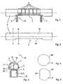
- FIG. 1 a side view of a device according to the invention with a rotation axis inserted therein;
- FIG. 2 shows a side view of a rotation axis with a first section line and a second section line; 3 shows a sectional view of the device according to the invention and the indicated axis of rotation,
- FIG. 4 shows a sectional illustration of the axis of rotation along the first section line from FIG. 2
- FIG. 5 shows a sectional illustration of the axis of rotation along the second section line from FIG. 2
- Figure 6 is a perspective view of the device according to the invention and
- Figure 7 is a schematic representation of the body according to the invention or the inventive arrangement.
- FIG. 1 shows a side view of a device 10 according to the invention with an axis of rotation 8 inserted therein.
- the device 10 has a base element 1, which is provided essentially as an elongated flat component, in particular as a sheet metal, and which has bent portions at its ends, which are designated by the reference numerals 2 and 3. Starting from the base element 1 of the device 10, a total of six spring elements 4 are arranged in FIG.
- the base element 1, its two angled portions 2, 3 and the spring elements 4 are inventively provided in particular in one piece and together form the device 10 according to the invention.
- the simplicity only one of the spring elements 4 is provided with the reference numeral 4 in Figure 6, another for better differentiation by the reference numeral 41.
- Base element 1 corresponds to the first designated by the reference numeral 4 spring element is bent - seen in the direction 9 from the right side of the base member 1 in a bending direction counterclockwise over the base member 1 away on its left side curved according to a special curve and it is bent by the reference numeral 41 further spring element curved starting from the left side of the base member 1 in a bending direction in a clockwise direction over the base member 1 away on its right side according to a special curve.
- the bending of the spring elements 4, 41 is not so complete that the spring elements 4, 41 again touch the base element 1 on their respective opposite sides, but a gap 12 is provided between the base element 1 and each of the spring elements 4, 41 As a result, the ends of the spring elements 4, 41 in Figure 6 are free and thus able to exert a restoring force, if they are deflected from their rest position.
- the gap 12 corresponds in the rest position of the spring elements 4, 41, for example, an opening of 20 °.
- the gap according to the invention therefore exists because the spring elements 4, 41, which are plastically deformed during their production usually starting from stamped sheet metal parts, after the bending process for their production elastically spring back a piece.
- the axis of rotation 8 is shown in side view with a first section line I - I and a second section line II - II.
- the axis of rotation 8 has in the region of the first cutting line in particular a circular cross-section, as shown in Figure 4, which is a sectional view of the rotation axis 8 along the first section line I - I, is shown.
- the lateral surface of the axis of rotation 8 is designated by the reference numeral 80 in the region of the first section line I-I in FIG.
- the lateral surface of the axis of rotation 8 in the region of the second section line II - II, ie in the region of the recess 5, divides into a first partial surface 50 of the lateral surface and in a second partial surface 70 of the lateral surface.
- the axis of rotation 8 along the second section line II-II is shown in FIG. 5 with its first partial region 50 of the lateral surface and its second partial region 70 of the lateral surface of the axis of rotation 8.
- FIG. 3 shows a sectional view of the device 10 according to the invention in the region of a spring element 4 and the axis of rotation 8 indicated by a dashed line.
- the device 10 in turn comprises the partial regions 2, 3 angled away from the base element 1, as well as the spring elements 4.
- two of the spring elements 4 are shown superimposed on one another.
- Each spring element 4 is bent in accordance with a specific curve starting from one side of the base member 1 in each of its bending direction - clockwise or counterclockwise - over the base member 1 out, but in Figure 3, the gap 12 described in Figure 6 between the free end a spring element 4 and its output side opposite to the base element 1 side of clarity is not shown.
- the special curve of the bending or curvature of the spring elements 4 is provided in such a way that the "clear" distance between the base element 1 and the "highest” position designated by the reference numeral 42, ie lying opposite the base element 1, means a "clear" distance
- Spring element 4 is smaller than the diameter 7 of the axis of rotation 8. This results in between the base element 1 and the spring elements 4 befind Anlagen - ie introduced into the device 10 - axis of rotation 8 to a deflection of the spring elements 4 and thus to a not shown in Figure 3 Restoring force of the spring elements 4, which presses the axis of rotation 8 against the base element 1.
- the axis of rotation 8 is introduced into the device 10, for example by means of a not shown in the figures and located at the front end of the axis of rotation 8 cones, which causes the spring elements 4 to expand the insertion of the axis of rotation 8 accordingly.
- FIG. 3 furthermore shows the first and second partial surfaces 50, 70.
- the particular curve of the bending of the spring elements 4 is chosen such that the axis of rotation 8 introduced into the device 10 is rotatable in any angular position relative to the device 10 without jamming. Therefore, in particular, a position of the first partial surface 50 in Berühungstitle for Base element 1 possible. This angular position is also referred to below as the first angular position.
- the device 10 is at least outside the region of the gap 12 with its base element 1 and at least one of the spring elements 4 on both partial surfaces 50, 70 of the lateral surface substantially completely.
- the spring elements 4 are less strongly deflected in this case, because in the range of the distance 42 - ie between the base member 1 and the highest point A of a spring element 4 - not the entire diameter 7 of the axis of rotation 8, but only the diameter 7 minus the Figure 2 known and there designated by the reference numeral 5 recess 8 of the axis of rotation must find room.
- each change in this position leads to a stronger deflection of the spring elements 4, so that a greater force is to be applied for such a change than for a change in the angular position starting from a different angular position.
- angular position - ie in particular those in which the base member 1 is in contact with the second part surface 70 of the lateral surface - it is such that the device 10 according to the invention with its spring elements 4, the axis of rotation 8 and thus the partial regions 50, 70 of the lateral surface essentially completely encloses except for the gap 12.
- Such another angular position is also referred to below generally as a second angular position.
- a second angular position Between the first and second angular position takes place a "up-and-down movement" of the spring elements 4. Of course, the size of the gap 12 changes.
- the number of spring elements 4 is basically indifferent. Surrounding the axis of rotation 8 of both sides of the base member 1 increases the stability of the axis of rotation 8 in the device 10, but also a single spring element 4 according to the invention is possible. Furthermore, it is provided according to the invention to provide the special curve of the bending of a spring element 4 for cooperating with the first partial surface 50. This makes it possible to ensure a particularly good locking of the body in further angular positions than the first angular position. This is realized for example by a flattened portion of the special curve of a spring element 4, not shown.
- FIG. 7 shows a schematic representation of the body 20 according to the invention or the arrangement 40 according to the invention.
- the body 20 includes a wire frame 30 connected to the device 10. According to the invention, this connection is provided, in particular, via the angled or bent regions 2, 3 of the device 10 according to the invention, which guarantee that the device 10 is connected to the body 20 in a mechanically non-rotatable manner.
- the wire frame 30 and the device 10 are surrounded or foamed together with a plastic sheath.
- the plastic wrapper is not specifically shown in Figure 7 with a reference numeral, but the body 20 substantially and in particular with respect to its outer dimensions, the plastic sheath.
- the inventive arrangement 40 comprises, in addition to the body according to the invention, the mounted rotary axis 8, which is also indicated in FIG. Furthermore, the spring elements 4 are indicated in Figure 7.
Landscapes
- Engineering & Computer Science (AREA)
- Mechanical Engineering (AREA)
- Springs (AREA)
- Clamps And Clips (AREA)
- Hooks, Suction Cups, And Attachment By Adhesive Means (AREA)
- Supports Or Holders For Household Use (AREA)
- Toys (AREA)
Claims (16)
- Dispositif (10) pour arrêter un corps (20) tournant autour d'un axe de rotation (8) présentant une surface latérale, dans lequel il est prévu que le corps (20) soit réglable dans une première position angulaire et dans une deuxième position angulaire par rapport à l'axe de rotation (8), dans lequel il est prévu que le corps (20) puisse être arrêté plus fortement dans la première position angulaire au moyen d'au moins une surface partielle (50) de la surface latérale que dans la deuxième position angulaire, par rapport à une rotation autour de l'axe de rotation (8), dans lequel il est prévu que le dispositif (10) et le corps (20) soient mécaniquement solidaires en rotation l'un de l'autre, dans lequel le dispositif (10) comprend au moins un élément de ressort (4), caractérisé en ce que le dispositif comprend au moins un autre élément de ressort (41) en plus de l'au moins un élément de ressort, dans lequel le dispositif (10) entoure de manière essentiellement complète, au moyen de ses éléments de ressort (4, 41) et d'un élément de base (1), la surface latérale (80) chaque fois jusqu'à une fente (12) entre chaque élément de ressort et l'élément de base, et dans lequel l'au moins un élément de ressort (4) et l'au moins un autre élément de ressort (41) sont assemblés à l'élément de base (1) sur des côtés différents de l'élément de base (1) par rapport à l'extension axiale de l'élément de base (1) le long de l'axe de rotation (8).
- Dispositif (10) selon la revendication 1, caractérisé en ce que la surface latérale (80) comprend une deuxième surface partielle (70), dans lequel le dispositif (10) s'applique de manière essentiellement complète sur les deux surfaces partielles (50, 70) de la surface latérale, au moins dans une des positions angulaires par rapport à l'axe de rotation (8), à l'extérieur de la région de la fente (12).
- Dispositif (10) selon l'une quelconque des revendications précédentes, caractérisé en ce que le dispositif (10) comprend un élément de base (1) en plus de l'au moins un élément de ressort (4), dans lequel l'élément de base (1) coopère, dans la première position angulaire du corps (20), avec la première surface partielle (50) de la surface latérale pour arrêter le corps (20) relativement plus fortement que dans la deuxième position angulaire du corps (20).
- Dispositif (10) selon l'une quelconque des revendications précédentes, caractérisé en ce que l'au moins un élément de ressort (4) entoure de manière essentiellement complète la surface latérale jusqu'à la fente (12) dans une première direction de flexion et dans lequel l'au moins un autre élément de ressort (41) entoure de manière essentiellement complète la surface latérale jusqu'à la fente (12) dans une deuxième direction de flexion opposée à la première direction de rotation.
- Dispositif (10) selon la revendication 4, caractérisé en ce que le dispositif (10) comprend une pluralité d'éléments de ressort (4), dans lequel les éléments de ressort (4) entourent la surface latérale en alternant dans la première et la deuxième directions de flexion le long de l'extension axiale de l'élément de base (1) parallèle à l'axe de rotation (8).
- Dispositif (10) selon la revendication 5, caractérisé en ce que la pluralité d'éléments de ressort (4) sont assemblés à l'élément de base (1), en alternance sur des côtés différents de l'élément de base (1), le long de l'extension axiale de l'élément de base (1) parallèle à l'axe de rotation (8).
- Dispositif (10) selon l'une quelconque des revendications précédentes, caractérisé en ce qu'il est prévu que le dispositif (10) et le corps (20) soient reliés mécaniquement l'un à l'autre, de telle manière que le dispositif (10) puisse coulisser par rapport au corps (20) dans une direction axiale par rapport à l'axe de rotation (8).
- Dispositif (10) selon l'une quelconque des revendications précédentes, caractérisé en ce que l'élément de base (1) et l'au moins un autre élément de ressort (4) sont assemblés l'un à l'autre en une seule pièce.
- Dispositif (10) selon l'une quelconque des revendications précédentes, caractérisé en ce que le dispositif (10) est constitué d'un métal ou d'un alliage, en particulier d'acier.
- Corps (20) avec un dispositif (10) selon l'une quelconque des revendications précédentes, caractérisé en ce que le corps (20) comprend un cadre de fils (30), dans lequel le dispositif (10) est relié au cadre de fils (30).
- Corps (20) selon la revendication 10, caractérisé en ce que le corps (20) comprend une partie en mousse, dans lequel la partie en mousse enrobe de manière essentiellement complète le cadre de fils (30) et le dispositif (10).
- Corps (20) selon la revendication 10 ou 11, caractérisé en ce que la partie en mousse est une partie en mousse de PPE (polypropylène expansé).
- Corps (20) selon la revendication 10, 11 ou 12, caractérisé en ce que le corps (20) est un écran pare-soleil, en particulier pour un véhicule.
- Système (40) pour arrêter un corps (20), dans lequel le système (40) comprend un dispositif (10) selon l'une quelconque des revendications 1 à 9, dans lequel le système (40) comprend en outre le corps (20) et l'axe de rotation (8), dans lequel il est prévu que la première surface partielle (50) de la surface latérale de l'axe de rotation (8) ne soit pas ronde ou soit aplatie.
- Système (40) selon la revendication 14, caractérisé en ce que la deuxième surface partielle (70) est essentiellement cylindrique.
- Utilisation d'un dispositif (10) selon l'une quelconque des revendications 1 à 9 pour arrêter un corps (20) selon l'une quelconque des revendications 11 à 13.
Applications Claiming Priority (3)
| Application Number | Priority Date | Filing Date | Title |
|---|---|---|---|
| DE10306733 | 2003-02-17 | ||
| DE10306733A DE10306733B4 (de) | 2003-02-17 | 2003-02-17 | Vorrichtung zur Arretierung, Körper und Anordnung |
| PCT/EP2004/001203 WO2004071796A1 (fr) | 2003-02-17 | 2004-02-10 | Dispositif d'arret, corps et systeme munis d'un tel dispositif |
Publications (2)
| Publication Number | Publication Date |
|---|---|
| EP1597100A1 EP1597100A1 (fr) | 2005-11-23 |
| EP1597100B1 true EP1597100B1 (fr) | 2008-02-06 |
Family
ID=32797485
Family Applications (1)
| Application Number | Title | Priority Date | Filing Date |
|---|---|---|---|
| EP04709606A Expired - Lifetime EP1597100B1 (fr) | 2003-02-17 | 2004-02-10 | Dispositif d'arret, corps et systeme munis d'un tel dispositif |
Country Status (7)
| Country | Link |
|---|---|
| US (1) | US7171112B2 (fr) |
| EP (1) | EP1597100B1 (fr) |
| JP (1) | JP4693764B2 (fr) |
| AT (1) | ATE385472T1 (fr) |
| DE (2) | DE10306733B4 (fr) |
| ES (1) | ES2301967T3 (fr) |
| WO (1) | WO2004071796A1 (fr) |
Families Citing this family (5)
| Publication number | Priority date | Publication date | Assignee | Title |
|---|---|---|---|---|
| DE102008020541A1 (de) | 2008-04-24 | 2009-10-29 | GM Global Technology Operations, Inc., Detroit | Sonnenblendschutzvorrichtung für die Fensterscheibe eines Kraftfahrzeugs und Kraftfahrzeug mit einer solchen Sonnenblendschutzvorrichtung |
| JP5191960B2 (ja) | 2008-07-28 | 2013-05-08 | 共和産業株式会社 | 車両用サンバイザ |
| US8870259B2 (en) * | 2008-11-12 | 2014-10-28 | Irvin Automotive Products, Inc. | Hybrid visor |
| US9963019B2 (en) * | 2016-05-11 | 2018-05-08 | Ford Global Technologies Llc | Sun visor having extended range of motion |
| US10081228B2 (en) * | 2016-11-08 | 2018-09-25 | Mahmoud Razzaghi | Car visor |
Family Cites Families (20)
| Publication number | Priority date | Publication date | Assignee | Title |
|---|---|---|---|---|
| US3378297A (en) * | 1966-05-27 | 1968-04-16 | Ternes Steel Company | Safety visor hinge |
| FR2194585B1 (fr) | 1972-08-02 | 1976-11-12 | Happich Gmbh Gebr | |
| SE437492B (sv) * | 1980-10-29 | 1985-03-04 | Autopart Sweden Ab | Sneppanordning, isynnerhet for solskydd i motorfordon |
| DE3261939D1 (en) * | 1981-06-19 | 1985-02-28 | Nissan Motor | Hinge structure for a sun visor or the like |
| ES2013846A6 (es) * | 1989-03-17 | 1990-06-01 | Gabas Cebollero Carlos | Resorte para bisagras de parasoles de vehiculos automoviles. |
| JPH0435915U (fr) * | 1990-07-23 | 1992-03-25 | ||
| JP3142631B2 (ja) * | 1992-04-13 | 2001-03-07 | 株式会社ネオックスラボ | 車両用サンバイザ |
| US5338083A (en) * | 1993-01-26 | 1994-08-16 | Plasta Fiber Industries Corp. | Visor detent spring clip |
| JP2600471Y2 (ja) * | 1993-08-27 | 1999-10-12 | デルタ工業株式会社 | 自動車用サンバイザの軸受構造 |
| US5564772A (en) * | 1994-09-01 | 1996-10-15 | Automotive Industries Manufacturing, Inc. | Apparatus for releasably holding a vehicle visor in a raised storage position and spring clip for use therein |
| US5967587A (en) * | 1997-03-18 | 1999-10-19 | Prince Corporation | Sliding visor |
| US5967588A (en) * | 1997-04-11 | 1999-10-19 | Prince Corporation | Visor control |
| US6010174A (en) * | 1997-04-14 | 2000-01-04 | Lear Automotive Dearborn, Inc. | Sliding visor |
| US5924748A (en) * | 1997-04-14 | 1999-07-20 | Ut Automotive Dearborh, Inc. | Visor torque control |
| US6120084A (en) * | 1997-10-02 | 2000-09-19 | Irvin Automotive Products, Inc. | Coated pivot pin/detent assembly |
| DE19835963A1 (de) * | 1998-08-08 | 2000-02-17 | Opel Adam Ag | Sonnenblende |
| US6220644B1 (en) * | 1999-03-10 | 2001-04-24 | Lear Automotive Dearborn, Inc. | Visor assembly |
| JP2001130256A (ja) * | 1999-11-08 | 2001-05-15 | Neoex Lab Inc | 車両用サンバイザ |
| DE10020106C1 (de) * | 2000-04-22 | 2001-05-17 | Johnson Contr Interiors Gmbh | Sonnenblende für Fahrzeuge |
| JP4115758B2 (ja) * | 2002-06-26 | 2008-07-09 | 共和産業株式会社 | 車両用サンバイザ |
-
2003
- 2003-02-17 DE DE10306733A patent/DE10306733B4/de not_active Expired - Fee Related
-
2004
- 2004-02-10 ES ES04709606T patent/ES2301967T3/es not_active Expired - Lifetime
- 2004-02-10 DE DE502004006128T patent/DE502004006128D1/de not_active Expired - Lifetime
- 2004-02-10 AT AT04709606T patent/ATE385472T1/de not_active IP Right Cessation
- 2004-02-10 EP EP04709606A patent/EP1597100B1/fr not_active Expired - Lifetime
- 2004-02-10 US US10/544,552 patent/US7171112B2/en not_active Expired - Fee Related
- 2004-02-10 JP JP2006501787A patent/JP4693764B2/ja not_active Expired - Fee Related
- 2004-02-10 WO PCT/EP2004/001203 patent/WO2004071796A1/fr not_active Ceased
Also Published As
| Publication number | Publication date |
|---|---|
| US7171112B2 (en) | 2007-01-30 |
| ES2301967T3 (es) | 2008-07-01 |
| JP4693764B2 (ja) | 2011-06-01 |
| DE502004006128D1 (de) | 2008-03-20 |
| DE10306733A1 (de) | 2004-09-02 |
| WO2004071796A1 (fr) | 2004-08-26 |
| DE10306733B4 (de) | 2005-08-18 |
| JP2006517884A (ja) | 2006-08-03 |
| US20060049655A1 (en) | 2006-03-09 |
| ATE385472T1 (de) | 2008-02-15 |
| EP1597100A1 (fr) | 2005-11-23 |
Similar Documents
| Publication | Publication Date | Title |
|---|---|---|
| EP1615798B1 (fr) | Dispositif de blocage et appuie-tete | |
| EP2611673B1 (fr) | Colonne de direction pour un véhicule automobile | |
| EP1725429B1 (fr) | Dispositif de reglage angulaire d'un composant pouvant tourner autour d'un axe de rotation, en particulier un accoudoir situe dans un vehicule | |
| EP3094212B1 (fr) | Articulation à pivot et meuble équipé d'une telle articulation à pivot | |
| EP0521294A1 (fr) | Tête de rasage, en particulier une unité de lames pour rasoir mécanique | |
| EP1687176B1 (fr) | Mecanisme d'enclenchement pour un siege de vehicule | |
| DE202006021191U1 (de) | Verstellbare Lenksäule für ein Kraftfahrzeug | |
| WO2015169645A1 (fr) | Rondelle-ressort pour commutateur rotatif indexé et commutateur rotatif indexé | |
| DE102012100287A1 (de) | Fahrzeugsitz und Verwendung eines gewellten Gleitstabelements | |
| EP1597100B1 (fr) | Dispositif d'arret, corps et systeme munis d'un tel dispositif | |
| DE3829109C2 (de) | Elektrischer Schalter, insbesondere Lenkstockschalter für Kraftfahrzeuge | |
| EP1924755B1 (fr) | Dispositif de blocage de porte avec boitier de butee | |
| EP1859117B1 (fr) | Charniere | |
| EP3460154A1 (fr) | Élément de retenue pour un couvercle ou un clapet d'un meuble | |
| DE69809321T2 (de) | Scharnier für ein Tür oder schwenkbares Paneel, insbesondere für ein Glaspaneel | |
| DE102013107876A1 (de) | Chirurgischer Clip, insbesondere Aneurysmenclip | |
| DE102012021702A1 (de) | Verriegelungsvorrichtung für eine Fahrzeugkomponente und Fahrzeugsitz | |
| DE202010012472U1 (de) | Gurthöheneinstellvorrichtung sowie Fahrzeugsitz mit einer solchen | |
| DE3900829C2 (de) | Zapfenlager für eine Sonnenblende | |
| EP0655671B1 (fr) | Dispositif de pédale en particulier pour la commande de l'embrayage d'un voiture | |
| DE10351658B4 (de) | Greifwerkzeug zur automatisierten Montage eines Sitzes | |
| EP1533175B1 (fr) | Dispositif pour l'affichage d'une position en hauteur et/ou d'une charge d'un siège de véhicule | |
| EP1471314B1 (fr) | Dispositif pour limiter le jeu axial | |
| EP4559779B1 (fr) | Dispositif de freinage à rouleau pour un conteneur de vente et de transport | |
| EP1495924B1 (fr) | Partie de carosserie d'un véhicule automobile, en particlier le capot |
Legal Events
| Date | Code | Title | Description |
|---|---|---|---|
| PUAI | Public reference made under article 153(3) epc to a published international application that has entered the european phase |
Free format text: ORIGINAL CODE: 0009012 |
|
| 17P | Request for examination filed |
Effective date: 20050919 |
|
| AK | Designated contracting states |
Kind code of ref document: A1 Designated state(s): AT BE BG CH CY CZ DE DK EE ES FI FR GB GR HU IE IT LI LU MC NL PT RO SE SI SK TR |
|
| AX | Request for extension of the european patent |
Extension state: AL LT LV MK |
|
| DAX | Request for extension of the european patent (deleted) | ||
| GRAP | Despatch of communication of intention to grant a patent |
Free format text: ORIGINAL CODE: EPIDOSNIGR1 |
|
| GRAS | Grant fee paid |
Free format text: ORIGINAL CODE: EPIDOSNIGR3 |
|
| GRAA | (expected) grant |
Free format text: ORIGINAL CODE: 0009210 |
|
| AK | Designated contracting states |
Kind code of ref document: B1 Designated state(s): AT BE BG CH CY CZ DE DK EE ES FI FR GB GR HU IE IT LI LU MC NL PT RO SE SI SK TR |
|
| REG | Reference to a national code |
Ref country code: GB Ref legal event code: FG4D Free format text: NOT ENGLISH |
|
| REG | Reference to a national code |
Ref country code: CH Ref legal event code: EP |
|
| REG | Reference to a national code |
Ref country code: IE Ref legal event code: FG4D Free format text: LANGUAGE OF EP DOCUMENT: GERMAN |
|
| REF | Corresponds to: |
Ref document number: 502004006128 Country of ref document: DE Date of ref document: 20080320 Kind code of ref document: P |
|
| GBT | Gb: translation of ep patent filed (gb section 77(6)(a)/1977) |
Effective date: 20080430 |
|
| REG | Reference to a national code |
Ref country code: ES Ref legal event code: FG2A Ref document number: 2301967 Country of ref document: ES Kind code of ref document: T3 |
|
| PG25 | Lapsed in a contracting state [announced via postgrant information from national office to epo] |
Ref country code: FI Free format text: LAPSE BECAUSE OF FAILURE TO SUBMIT A TRANSLATION OF THE DESCRIPTION OR TO PAY THE FEE WITHIN THE PRESCRIBED TIME-LIMIT Effective date: 20080206 |
|
| NLV1 | Nl: lapsed or annulled due to failure to fulfill the requirements of art. 29p and 29m of the patents act | ||
| BERE | Be: lapsed |
Owner name: JOHNSON CONTROLS INTERIORS G.M.B.H. & CO. KG Effective date: 20080228 |
|
| PG25 | Lapsed in a contracting state [announced via postgrant information from national office to epo] |
Ref country code: SI Free format text: LAPSE BECAUSE OF FAILURE TO SUBMIT A TRANSLATION OF THE DESCRIPTION OR TO PAY THE FEE WITHIN THE PRESCRIBED TIME-LIMIT Effective date: 20080206 |
|
| REG | Reference to a national code |
Ref country code: CH Ref legal event code: PL |
|
| REG | Reference to a national code |
Ref country code: IE Ref legal event code: FD4D |
|
| ET | Fr: translation filed | ||
| PG25 | Lapsed in a contracting state [announced via postgrant information from national office to epo] |
Ref country code: DK Free format text: LAPSE BECAUSE OF FAILURE TO SUBMIT A TRANSLATION OF THE DESCRIPTION OR TO PAY THE FEE WITHIN THE PRESCRIBED TIME-LIMIT Effective date: 20080206 Ref country code: IE Free format text: LAPSE BECAUSE OF FAILURE TO SUBMIT A TRANSLATION OF THE DESCRIPTION OR TO PAY THE FEE WITHIN THE PRESCRIBED TIME-LIMIT Effective date: 20080206 Ref country code: PT Free format text: LAPSE BECAUSE OF FAILURE TO SUBMIT A TRANSLATION OF THE DESCRIPTION OR TO PAY THE FEE WITHIN THE PRESCRIBED TIME-LIMIT Effective date: 20080707 Ref country code: SK Free format text: LAPSE BECAUSE OF FAILURE TO SUBMIT A TRANSLATION OF THE DESCRIPTION OR TO PAY THE FEE WITHIN THE PRESCRIBED TIME-LIMIT Effective date: 20080206 Ref country code: SE Free format text: LAPSE BECAUSE OF FAILURE TO SUBMIT A TRANSLATION OF THE DESCRIPTION OR TO PAY THE FEE WITHIN THE PRESCRIBED TIME-LIMIT Effective date: 20080506 Ref country code: CH Free format text: LAPSE BECAUSE OF NON-PAYMENT OF DUE FEES Effective date: 20080229 Ref country code: LI Free format text: LAPSE BECAUSE OF NON-PAYMENT OF DUE FEES Effective date: 20080229 Ref country code: MC Free format text: LAPSE BECAUSE OF NON-PAYMENT OF DUE FEES Effective date: 20080228 Ref country code: NL Free format text: LAPSE BECAUSE OF FAILURE TO SUBMIT A TRANSLATION OF THE DESCRIPTION OR TO PAY THE FEE WITHIN THE PRESCRIBED TIME-LIMIT Effective date: 20080206 Ref country code: CZ Free format text: LAPSE BECAUSE OF FAILURE TO SUBMIT A TRANSLATION OF THE DESCRIPTION OR TO PAY THE FEE WITHIN THE PRESCRIBED TIME-LIMIT Effective date: 20080206 |
|
| PG25 | Lapsed in a contracting state [announced via postgrant information from national office to epo] |
Ref country code: RO Free format text: LAPSE BECAUSE OF FAILURE TO SUBMIT A TRANSLATION OF THE DESCRIPTION OR TO PAY THE FEE WITHIN THE PRESCRIBED TIME-LIMIT Effective date: 20080206 |
|
| PLBE | No opposition filed within time limit |
Free format text: ORIGINAL CODE: 0009261 |
|
| STAA | Information on the status of an ep patent application or granted ep patent |
Free format text: STATUS: NO OPPOSITION FILED WITHIN TIME LIMIT |
|
| 26N | No opposition filed |
Effective date: 20081107 |
|
| PG25 | Lapsed in a contracting state [announced via postgrant information from national office to epo] |
Ref country code: EE Free format text: LAPSE BECAUSE OF FAILURE TO SUBMIT A TRANSLATION OF THE DESCRIPTION OR TO PAY THE FEE WITHIN THE PRESCRIBED TIME-LIMIT Effective date: 20080206 |
|
| PG25 | Lapsed in a contracting state [announced via postgrant information from national office to epo] |
Ref country code: BE Free format text: LAPSE BECAUSE OF NON-PAYMENT OF DUE FEES Effective date: 20080228 |
|
| PG25 | Lapsed in a contracting state [announced via postgrant information from national office to epo] |
Ref country code: AT Free format text: LAPSE BECAUSE OF NON-PAYMENT OF DUE FEES Effective date: 20080210 Ref country code: BG Free format text: LAPSE BECAUSE OF FAILURE TO SUBMIT A TRANSLATION OF THE DESCRIPTION OR TO PAY THE FEE WITHIN THE PRESCRIBED TIME-LIMIT Effective date: 20080506 |
|
| PG25 | Lapsed in a contracting state [announced via postgrant information from national office to epo] |
Ref country code: CY Free format text: LAPSE BECAUSE OF FAILURE TO SUBMIT A TRANSLATION OF THE DESCRIPTION OR TO PAY THE FEE WITHIN THE PRESCRIBED TIME-LIMIT Effective date: 20080206 |
|
| PG25 | Lapsed in a contracting state [announced via postgrant information from national office to epo] |
Ref country code: HU Free format text: LAPSE BECAUSE OF FAILURE TO SUBMIT A TRANSLATION OF THE DESCRIPTION OR TO PAY THE FEE WITHIN THE PRESCRIBED TIME-LIMIT Effective date: 20080807 Ref country code: LU Free format text: LAPSE BECAUSE OF NON-PAYMENT OF DUE FEES Effective date: 20080210 |
|
| PG25 | Lapsed in a contracting state [announced via postgrant information from national office to epo] |
Ref country code: TR Free format text: LAPSE BECAUSE OF FAILURE TO SUBMIT A TRANSLATION OF THE DESCRIPTION OR TO PAY THE FEE WITHIN THE PRESCRIBED TIME-LIMIT Effective date: 20080206 |
|
| PG25 | Lapsed in a contracting state [announced via postgrant information from national office to epo] |
Ref country code: GR Free format text: LAPSE BECAUSE OF FAILURE TO SUBMIT A TRANSLATION OF THE DESCRIPTION OR TO PAY THE FEE WITHIN THE PRESCRIBED TIME-LIMIT Effective date: 20080507 |
|
| PGFP | Annual fee paid to national office [announced via postgrant information from national office to epo] |
Ref country code: IT Payment date: 20140225 Year of fee payment: 11 |
|
| PGFP | Annual fee paid to national office [announced via postgrant information from national office to epo] |
Ref country code: GB Payment date: 20140218 Year of fee payment: 11 |
|
| REG | Reference to a national code |
Ref country code: DE Ref legal event code: R082 Ref document number: 502004006128 Country of ref document: DE Representative=s name: MEISSNER, BOLTE & PARTNER GBR, DE Ref country code: DE Ref legal event code: R082 Ref document number: 502004006128 Country of ref document: DE Ref country code: DE Ref legal event code: R082 Ref document number: 502004006128 Country of ref document: DE Representative=s name: MEISSNER BOLTE PATENTANWAELTE RECHTSANWAELTE P, DE |
|
| REG | Reference to a national code |
Ref country code: DE Ref legal event code: R082 Ref document number: 502004006128 Country of ref document: DE Representative=s name: MEISSNER, BOLTE & PARTNER GBR, DE Ref country code: DE Ref legal event code: R082 Ref document number: 502004006128 Country of ref document: DE Representative=s name: MEISSNER BOLTE PATENTANWAELTE RECHTSANWAELTE P, DE |
|
| GBPC | Gb: european patent ceased through non-payment of renewal fee |
Effective date: 20150210 |
|
| PG25 | Lapsed in a contracting state [announced via postgrant information from national office to epo] |
Ref country code: IT Free format text: LAPSE BECAUSE OF NON-PAYMENT OF DUE FEES Effective date: 20150210 |
|
| PG25 | Lapsed in a contracting state [announced via postgrant information from national office to epo] |
Ref country code: GB Free format text: LAPSE BECAUSE OF NON-PAYMENT OF DUE FEES Effective date: 20150210 |
|
| REG | Reference to a national code |
Ref country code: FR Ref legal event code: PLFP Year of fee payment: 13 |
|
| REG | Reference to a national code |
Ref country code: FR Ref legal event code: PLFP Year of fee payment: 14 |
|
| REG | Reference to a national code |
Ref country code: FR Ref legal event code: PLFP Year of fee payment: 15 |
|
| PGFP | Annual fee paid to national office [announced via postgrant information from national office to epo] |
Ref country code: ES Payment date: 20180315 Year of fee payment: 15 |
|
| PGFP | Annual fee paid to national office [announced via postgrant information from national office to epo] |
Ref country code: FR Payment date: 20180223 Year of fee payment: 15 |
|
| PGFP | Annual fee paid to national office [announced via postgrant information from national office to epo] |
Ref country code: DE Payment date: 20190821 Year of fee payment: 16 |
|
| PG25 | Lapsed in a contracting state [announced via postgrant information from national office to epo] |
Ref country code: FR Free format text: LAPSE BECAUSE OF NON-PAYMENT OF DUE FEES Effective date: 20190228 |
|
| REG | Reference to a national code |
Ref country code: ES Ref legal event code: FD2A Effective date: 20200327 |
|
| PG25 | Lapsed in a contracting state [announced via postgrant information from national office to epo] |
Ref country code: ES Free format text: LAPSE BECAUSE OF NON-PAYMENT OF DUE FEES Effective date: 20190211 |
|
| REG | Reference to a national code |
Ref country code: DE Ref legal event code: R119 Ref document number: 502004006128 Country of ref document: DE |
|
| PG25 | Lapsed in a contracting state [announced via postgrant information from national office to epo] |
Ref country code: DE Free format text: LAPSE BECAUSE OF NON-PAYMENT OF DUE FEES Effective date: 20200901 |