EP1687176B1 - Mecanisme d'enclenchement pour un siege de vehicule - Google Patents
Mecanisme d'enclenchement pour un siege de vehicule Download PDFInfo
- Publication number
- EP1687176B1 EP1687176B1 EP04820588A EP04820588A EP1687176B1 EP 1687176 B1 EP1687176 B1 EP 1687176B1 EP 04820588 A EP04820588 A EP 04820588A EP 04820588 A EP04820588 A EP 04820588A EP 1687176 B1 EP1687176 B1 EP 1687176B1
- Authority
- EP
- European Patent Office
- Prior art keywords
- spring
- eccentric
- fitting
- fitting part
- vehicle seat
- Prior art date
- Legal status (The legal status is an assumption and is not a legal conclusion. Google has not performed a legal analysis and makes no representation as to the accuracy of the status listed.)
- Expired - Fee Related
Links
Images
Classifications
-
- B—PERFORMING OPERATIONS; TRANSPORTING
- B60—VEHICLES IN GENERAL
- B60N—SEATS SPECIALLY ADAPTED FOR VEHICLES; VEHICLE PASSENGER ACCOMMODATION NOT OTHERWISE PROVIDED FOR
- B60N2/00—Seats specially adapted for vehicles; Arrangement or mounting of seats in vehicles
- B60N2/02—Seats specially adapted for vehicles; Arrangement or mounting of seats in vehicles the seat or part thereof being movable, e.g. adjustable
- B60N2/22—Seats specially adapted for vehicles; Arrangement or mounting of seats in vehicles the seat or part thereof being movable, e.g. adjustable the back-rest being adjustable
- B60N2/235—Seats specially adapted for vehicles; Arrangement or mounting of seats in vehicles the seat or part thereof being movable, e.g. adjustable the back-rest being adjustable by gear-pawl type mechanisms
- B60N2/2356—Seats specially adapted for vehicles; Arrangement or mounting of seats in vehicles the seat or part thereof being movable, e.g. adjustable the back-rest being adjustable by gear-pawl type mechanisms with internal pawls
- B60N2/236—Seats specially adapted for vehicles; Arrangement or mounting of seats in vehicles the seat or part thereof being movable, e.g. adjustable the back-rest being adjustable by gear-pawl type mechanisms with internal pawls linearly movable
-
- B—PERFORMING OPERATIONS; TRANSPORTING
- B60—VEHICLES IN GENERAL
- B60N—SEATS SPECIALLY ADAPTED FOR VEHICLES; VEHICLE PASSENGER ACCOMMODATION NOT OTHERWISE PROVIDED FOR
- B60N2/00—Seats specially adapted for vehicles; Arrangement or mounting of seats in vehicles
- B60N2/02—Seats specially adapted for vehicles; Arrangement or mounting of seats in vehicles the seat or part thereof being movable, e.g. adjustable
- B60N2/22—Seats specially adapted for vehicles; Arrangement or mounting of seats in vehicles the seat or part thereof being movable, e.g. adjustable the back-rest being adjustable
-
- Y—GENERAL TAGGING OF NEW TECHNOLOGICAL DEVELOPMENTS; GENERAL TAGGING OF CROSS-SECTIONAL TECHNOLOGIES SPANNING OVER SEVERAL SECTIONS OF THE IPC; TECHNICAL SUBJECTS COVERED BY FORMER USPC CROSS-REFERENCE ART COLLECTIONS [XRACs] AND DIGESTS
- Y10—TECHNICAL SUBJECTS COVERED BY FORMER USPC
- Y10T—TECHNICAL SUBJECTS COVERED BY FORMER US CLASSIFICATION
- Y10T74/00—Machine element or mechanism
- Y10T74/20—Control lever and linkage systems
- Y10T74/20576—Elements
- Y10T74/20636—Detents
Definitions
- the invention relates to a catch fitting for a vehicle seat, in particular for a motor vehicle seat, with the features of the preamble of claim 1.
- a detent fitting is known in which two biased, arranged laterally of the eccentric coil springs act on the eccentric, which in turn acts on two bars, in the direction radially outward.
- the two bars cooperate in their radially outer position with the first fitting part to lock the catch fitting.
- To unlock the detent fitting of the eccentric is rotated by external loading against the bias of the springs, whereupon a seated on the eccentric control disc pulls the two provided with protruding lugs bolt radially inward.
- the WO 00/06414 A1 discloses a locking fitting of the type mentioned, having all the features according to the preamble of claim 1.
- the invention is based on the object to improve a locking fitting of the type mentioned, in particular to reduce the number of components. This object is achieved by a catch fitting with the features of claim 1.
- Advantageous embodiments are the subject of the dependent claims.
- the spring orbits the axis, ie covers almost the entire space, which is defined between the fitting parts and within which are arranged for the locking of the detent fitting components are arranged, for example, the eccentric, the bolt provided and the spring.
- the main task of the spring ie the application of the eccentric, a single spring which can act on the eccentric at least approximately symmetrically. This reduces the number of necessary components.
- the spring is preferably supported on the second bolt part leading the intended bolt.
- the spring can perform a further task, namely pull the bolt inward, which also reduces the number of necessary components, thus reducing the cost and facilitates installation.
- each bolt provided on a nose, a cam, a projection or the like, which is or for example pressed out of the material of the bolt.
- the spring with at least one turn or a switching contour is arranged radially outside the same or the same, so that they can take the bolt with a movement radially inwardly.
- the spring When the eccentric is applied externally, for example by a shaft acting in the region of the shaft or the like, the spring is contracted, for example, by the spring is mounted inside the eccentric and outside the fitting part.
- the contracting spring then pulls the provided latch on its nose, cam, projection or the like radially inward, for example, directly by means of the winding or by means of a switching contour.
- the spring sits inside preferably positive fit on the eccentric to ensure a good entrainment.
- This can be realized by projections and / or receptacles, also at the inner end of the spring.
- an inner ring can be formed on the inside, which sits on the eccentric and surrounds this ring.
- projections and / or receptacles are provided to form the positive connection.
- the spring is preferably spirally punched out of a thin spring steel sheet, so that at the same time formed the projections and / or recordings and can be impressed by a geometry deviation for later installation state, a bias.
- An inventive vehicle seat has at least one, preferably two of the latching fittings according to the invention, which are connected to each other for example by means of a transmission rod.
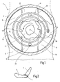
- the first embodiment relates to a locking fitting 1 of a vehicle seat for a motor vehicle, which includes a fitting upper part, hereinafter referred to as the first fitting part 2, and a fitting lower part, hereinafter referred to as a second fitting part 3 comprises.
- a detent fitting 1 On the two sides of the vehicle seat each a detent fitting 1 is arranged.
- the backrest 4 attached to the first fitting part 2 is attached by means of the two locking fittings 1 on the seat part 5 of the vehicle seat.
- the two locking fittings 1 are interconnected by a transmission rod, not shown.
- the first fitting part 2 has on its side facing the second fitting part 3 inside a cylindrical recess which defines a space 8 between the two fitting parts 2 and 3.
- An eccentric 11 in the form of a circular disc with two point-symmetrical pairs of two cams on the outer circumference is seated within the installation space 8 on a driver, not shown, the again rotatably seated on the transmission rod, so that the eccentric 11 is rotatable about a central axis A.
- latch 13 In the same plane as the eccentric 11, but with a greater radial distance from the axis A, two flat tooth segments, hereinafter referred to as latch 13, are arranged within the installation space 8, which is offset by 180 ° (ie point-symmetrical to each other) movable in the radial direction are.
- Each latch 13 carries at its radially outer end on its edge a toothing for cooperation with the ring gear 10 and is provided at its radially inner end at the edge with a saunockigen contour, which with the eccentric acting as a control 11 interacts.
- the extending in the radial direction of the edge surfaces of the bolt 13 are parallel to each other over most of their length.
- the second fitting part 3 has a projecting into the space 8 guide 15 for lying in the same plane latch 13.
- the guide 15 consists of four mirror-symmetrically arranged segments, which form in pairs a channel for each bar 13, which abuts with its parallel edge surfaces on the side walls of the channel.
- the guide 15 also serves to support the first fitting part 2 on the second fitting part 3, i. the first fitting part 2 sits with its ring gear 10 on the cylindrically curved outer side of the four segments.
- the outer spring end 17 'of the single spring 17 is clamped on the second fitting part 3, clipped or otherwise secured.
- the spring 17 is preferably installed with bias so that the spring 17 acts on the eccentric 11 and rotates about the axis A that its cams on the contour of the latch 13 radially outwardly press into the sprocket 10, ie the eccentric with bias 11 is applied in the direction of rotation in the clockwise direction in the drawing.
- the locking fitting 1 is locked so.
- the eccentric 11 is rotated by the transmission rod about the axis A counterclockwise, i. externally applied, which is indicated in the drawing by a curved arrow, he pulls the spring 17 together.
- a non-illustrated, non-rotatably seated on the eccentric 11 control disk is rotated, which has scenes for the lugs 23.
- the lugs 23 are acted upon by the spring 17 - and optionally by the control disk - in the radial direction inwardly, whereby the bolt 13 are pulled radially inward.
- the locking fitting 1 is thus unlocked, so that the backrest 4 is pivotable relative to the seat part 5.
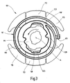
- the second embodiment is similar to the first embodiment, as far as not described below, which is why the same and equivalent components bear 100 higher reference numerals.
- the bolt 113 which are guided in the guide 115, radially outward.
- the eccentric 117 acted upon, spirally formed, single spring 117 is provided, which surrounds the axis A.
- the outer end 117 ' is in turn attached to the second fitting part.
- the spring 117 continues in one piece in an inner ring 118, which on the one hand engages in corresponding receptacles of the eccentric 11 by means of projections 117 and on the other hand has two switching contours 118.
- Each switching contour 118 ' is arranged radially outside a cam 123, which is pronounced from the latch 113.
- the spring 117 is contracted, pulling the latch 113 by means of the switching contour 118 'and the cam 123 radially inwardly to to unlock the catch fitting.
Claims (6)
- - Armature à enclenchement pour un siège de véhicule, en particulier pour un siège de véhicule automobile, comprenant(a) une première partie d'armature (2),(b) une seconde partie d'armature (3) qui est mobile par rapport à la première partie d'armature (2),(c) au moins un verrou (13 ; 113) qui coopère avec la première partie d'armature (2) et est guidé par la seconde partie d'armature (3), chaque verrou prévu (13 ; 113) comprenant un taquet (23) ou une came (123), ou similaires, qui ressort/ressortent dans la direction axiale ;(d) un excentrique (11 ; 111) qui agit sur le verrou (13 ; 113) et est rotatif autour d'un axe (A), l'excentrique (11 ; 111) étant disposé radialement à l'intérieur et les verrous prévus (13 ; 113) étant disposés radialement à l'extérieur ;(e) et au moins un ressort en spirale (17 ; 117) qui entoure l'axe (A) et charge l'excentrique (11 ; 111), l'excentrique (11 ; 111) poussant radialement vers l'extérieur lors de la charge par le ressort (17 ; 117) les verrous prévus (13 ; 113), afin de coopérer avec la première partie d'armature (2), et contractant le ressort (17 ; 117) lors de la charge externe,
caractérisée par le fait que(f) le ressort (17 ; 117) est disposé avec au moins un enroulement ou un contour de manoeuvre (118') radialement à l'extérieur du taquet (23) ou de la came (123) ou similaires ; et(g) le ressort se contractant (17 ; 117) charge vers l'intérieur les verrous prévus (13 ; 113) contre les taquets (23) ou les cames (123) ou similaires en direction radiale vers l'intérieur, et par là tire radialement vers l'intérieur les verrous prévus (13 ; 113). - - Armature à enclenchement selon la revendication 1, caractérisée par le fait que le ressort (17 ; 117) est posé avec son extrémité externe (17', 117') contre la seconde partie d'armature (3).
- - Armature à enclenchement selon l'une des revendications 1 ou 2, caractérisée par le fait que le ressort (17 ; 117) repose à l'intérieur par ajustement géométrique sur l'excentrique (11 ; 111).
- - Armature à enclenchement selon la revendication 3, caractérisée par le fait qu'une bague intérieure (118) est formée à l'intérieur sur le ressort (117), laquelle bague repose sur l'excentrique (111).
- - Armature à enclenchement selon l'une quelconque des revendications précédentes, caractérisée par le fait que le ressort (17 ; 117) est découpé en spirale dans une mince tôle en acier à ressorts.
- - Siège de véhicule avec un dossier (4) qui est inclinable par rapport à une partie de siège (5), au moins une armature à enclenchement telle que définie à l'une quelconque des revendications précédentes servant de réglage d'inclinaison.
Priority Applications (1)
| Application Number | Priority Date | Filing Date | Title |
|---|---|---|---|
| PL04820588T PL1687176T3 (pl) | 2003-11-28 | 2004-11-12 | Zatrzaskowe okucie do siedzenia w pojeździe |
Applications Claiming Priority (2)
| Application Number | Priority Date | Filing Date | Title |
|---|---|---|---|
| DE10355820A DE10355820B3 (de) | 2003-11-28 | 2003-11-28 | Rastbeschlag für einen Fahrzeugsitz |
| PCT/EP2004/012821 WO2005061270A1 (fr) | 2003-11-28 | 2004-11-12 | Mécanisme à enclenchement pour un siège de véhicule |
Publications (2)
| Publication Number | Publication Date |
|---|---|
| EP1687176A1 EP1687176A1 (fr) | 2006-08-09 |
| EP1687176B1 true EP1687176B1 (fr) | 2008-05-07 |
Family
ID=34442347
Family Applications (1)
| Application Number | Title | Priority Date | Filing Date |
|---|---|---|---|
| EP04820588A Expired - Fee Related EP1687176B1 (fr) | 2003-11-28 | 2004-11-12 | Mecanisme d'enclenchement pour un siege de vehicule |
Country Status (8)
| Country | Link |
|---|---|
| US (1) | US7204555B2 (fr) |
| EP (1) | EP1687176B1 (fr) |
| JP (1) | JP4567003B2 (fr) |
| KR (1) | KR101122934B1 (fr) |
| CN (1) | CN100564099C (fr) |
| DE (2) | DE10355820B3 (fr) |
| PL (1) | PL1687176T3 (fr) |
| WO (1) | WO2005061270A1 (fr) |
Families Citing this family (22)
| Publication number | Priority date | Publication date | Assignee | Title |
|---|---|---|---|---|
| JP4883341B2 (ja) * | 2005-08-24 | 2012-02-22 | アイシン精機株式会社 | シートリクライニング装置 |
| US7246598B2 (en) * | 2005-11-02 | 2007-07-24 | Keihin Corporation | Accelerator pedal device |
| CN101378678B (zh) * | 2006-02-16 | 2010-06-02 | 株式会社今仙电机制作所 | 斜靠装置 |
| DE102007007362B4 (de) * | 2007-02-14 | 2009-07-09 | Faurecia Autositze Gmbh | Verstellmechanismus |
| JP4308859B2 (ja) * | 2007-02-20 | 2009-08-05 | 株式会社今仙電機製作所 | リクライニング装置 |
| US7703852B2 (en) * | 2007-12-03 | 2010-04-27 | Lear Corporation | Heavy duty reclining mechanism for vehicle seats |
| WO2009091980A1 (fr) | 2008-01-17 | 2009-07-23 | Fisher Dynamics Corporation | Mécanisme de siège inclinable rond |
| DE102008029438B4 (de) * | 2008-06-16 | 2014-05-22 | Keiper Gmbh & Co. Kg | Beschlag für einen Fahrzeugsitz |
| DE102009022777A1 (de) * | 2009-05-20 | 2010-11-25 | Brose Fahrzeugteile Gmbh & Co. Kommanditgesellschaft, Coburg | Rastbeschlag |
| DE102009041492A1 (de) | 2009-09-10 | 2011-03-24 | Keiper Gmbh & Co. Kg | Beschlag für einen Fahrzeugsitz |
| DE102011106285B4 (de) * | 2011-07-04 | 2013-08-22 | Keiper Gmbh & Co. Kg | Beschlagsystem für einen Fahrzeugsitz und Fahrzeugsitz |
| US9296315B2 (en) | 2013-02-26 | 2016-03-29 | Fisher & Company, Incorporated | Recliner mechanism with backdriving feature |
| CN103241145B (zh) * | 2013-05-23 | 2016-03-30 | 烟台延锋江森座椅有限责任公司 | 一种用于座椅调角器的收缩式弹簧止动配件 |
| US9902297B2 (en) | 2014-06-11 | 2018-02-27 | Fisher & Company, Incorporated | Latch mechanism with locking feature |
| DE102015215367B4 (de) * | 2015-03-13 | 2020-12-17 | Adient Luxembourg Holding S.À R.L. | Beschlagsystem für einen Fahrzeugsitz sowie Fahrzeugsitz |
| JP6682300B2 (ja) * | 2016-03-04 | 2020-04-15 | シロキ工業株式会社 | シートリクライニング装置 |
| DE102016215806B4 (de) * | 2016-08-23 | 2024-01-04 | Volkswagen Aktiengesellschaft | Rückenlehnenanordnung für ein Kraftfahrzeug sowie Kraftfahrzeug |
| DE102016225834B4 (de) * | 2016-10-04 | 2020-01-09 | Adient Luxembourg Holding S.À R.L. | Fahrzeugsitz, insbesondere kraftfahrzeugsitz |
| US10076978B2 (en) * | 2016-10-20 | 2018-09-18 | Ford Global Technologies, Llc | Power lift and recliner release/fold device |
| CN107668995A (zh) * | 2017-10-06 | 2018-02-09 | 中山市东立家具配件有限公司 | 一种办公椅的倾仰控制装置 |
| KR102001508B1 (ko) | 2017-12-26 | 2019-07-18 | 현대트랜시스(주) | 차량의 시트 리클라이너 |
| US11726519B2 (en) | 2021-12-17 | 2023-08-15 | Raytheon Company | Clocking spring for a rotatable shaft |
Family Cites Families (19)
| Publication number | Priority date | Publication date | Assignee | Title |
|---|---|---|---|---|
| DE2641582A1 (de) * | 1976-09-16 | 1978-03-23 | Keiper Automobiltechnik Gmbh | Gelenkbeschlag fuer fahrzeugsitze mit in bezug auf das sitzteil schwenkbarer rueckenlehne |
| US4082352A (en) * | 1977-01-13 | 1978-04-04 | Lear Siegler, Inc. | Seat back recliner |
| JP4265024B2 (ja) * | 1998-06-22 | 2009-05-20 | トヨタ紡織株式会社 | リクライニング装置 |
| EP1100694B1 (fr) * | 1998-07-28 | 2003-05-21 | Magna Interior Systems Inc. | Mécanisme d'inclinaison |
| JP2000192992A (ja) * | 1998-12-25 | 2000-07-11 | Toyota Autom Loom Works Ltd | 動力伝達機構 |
| DE19904300C1 (de) * | 1999-01-28 | 2000-08-03 | Keiper Gmbh & Co | Rastbeschlag für einen Fahrzeugsitz |
| JP4374657B2 (ja) * | 1999-06-08 | 2009-12-02 | アイシン精機株式会社 | シートリクライニング装置 |
| EP1195115B1 (fr) * | 1999-06-16 | 2009-12-23 | NHK Spring Co., Ltd. | Dispositif d'inclinaison |
| US6312053B1 (en) * | 1999-07-20 | 2001-11-06 | Magna Interior Systems, Inc. | Recliner assembly |
| JP4457434B2 (ja) * | 1999-08-02 | 2010-04-28 | トヨタ紡織株式会社 | リクライニング装置 |
| FR2801850B1 (fr) * | 2000-11-10 | 2004-01-16 | Faurecia Sieges Automobile | Mecanisme d'articulation pour siege de vehicule et siege equipe d'un tel mecanisme |
| JP2002327666A (ja) * | 2001-03-01 | 2002-11-15 | Starting Ind Co Ltd | スタータ装置 |
| JP4595256B2 (ja) * | 2001-06-26 | 2010-12-08 | アイシン精機株式会社 | シートリクライニング装置 |
| DE10217873B4 (de) * | 2001-04-23 | 2008-08-14 | Aisin Seiki K.K., Kariya | Gelenkbeschlag |
| WO2003022622A1 (fr) * | 2001-09-06 | 2003-03-20 | Keiper Gmbh & Co. | Ferrure pour un siege de voiture |
| KR100446127B1 (ko) * | 2002-03-14 | 2004-08-30 | 주식회사다스 | 자동차용 시트 리클라이닝 장치 |
| JP4032806B2 (ja) | 2002-04-18 | 2008-01-16 | トヨタ紡織株式会社 | リクライニング装置 |
| JP3991780B2 (ja) * | 2002-06-19 | 2007-10-17 | アイシン精機株式会社 | シートリクライニング装置 |
| US6883869B2 (en) * | 2003-03-10 | 2005-04-26 | Porter Group, Llc | Vehicle seat back recliner |
-
2003
- 2003-11-28 DE DE10355820A patent/DE10355820B3/de not_active Expired - Fee Related
-
2004
- 2004-11-12 CN CNB2004800086384A patent/CN100564099C/zh not_active Expired - Fee Related
- 2004-11-12 DE DE502004007088T patent/DE502004007088D1/de active Active
- 2004-11-12 WO PCT/EP2004/012821 patent/WO2005061270A1/fr active IP Right Grant
- 2004-11-12 KR KR1020057016006A patent/KR101122934B1/ko not_active IP Right Cessation
- 2004-11-12 JP JP2006540262A patent/JP4567003B2/ja not_active Expired - Fee Related
- 2004-11-12 PL PL04820588T patent/PL1687176T3/pl unknown
- 2004-11-12 EP EP04820588A patent/EP1687176B1/fr not_active Expired - Fee Related
-
2006
- 2006-04-26 US US11/411,719 patent/US7204555B2/en not_active Expired - Fee Related
Also Published As
| Publication number | Publication date |
|---|---|
| US20060185466A1 (en) | 2006-08-24 |
| JP2007512173A (ja) | 2007-05-17 |
| CN100564099C (zh) | 2009-12-02 |
| CN1767967A (zh) | 2006-05-03 |
| DE502004007088D1 (de) | 2008-06-19 |
| KR20060112196A (ko) | 2006-10-31 |
| WO2005061270A1 (fr) | 2005-07-07 |
| US7204555B2 (en) | 2007-04-17 |
| PL1687176T3 (pl) | 2008-10-31 |
| EP1687176A1 (fr) | 2006-08-09 |
| DE10355820B3 (de) | 2005-05-19 |
| JP4567003B2 (ja) | 2010-10-20 |
| KR101122934B1 (ko) | 2012-03-20 |
Similar Documents
| Publication | Publication Date | Title |
|---|---|---|
| EP1687176B1 (fr) | Mecanisme d'enclenchement pour un siege de vehicule | |
| DE102005054490B4 (de) | Beschlag für einen Fahrzeugsitz | |
| EP1799499B1 (fr) | Ferrure de siege de vehicule | |
| DE19904299C1 (de) | Rastbeschlag für einen Fahrzeugsitz | |
| EP2566719B1 (fr) | Ferrure pour un siège de véhicule | |
| EP1768870B1 (fr) | Armature pour siege de vehicule | |
| EP1592577B1 (fr) | Mecanisme a engrenage pour siege de vehicule | |
| DE102005026658B3 (de) | Neigungsverstellbeschlag für die Rückenlehne eines Kraftfahrzeugsitzes | |
| EP1720729B1 (fr) | Ferrure pour siege de vehicule automobile | |
| DE102009041492A1 (de) | Beschlag für einen Fahrzeugsitz | |
| DE102011015139B4 (de) | Verstellmechanismus mit einem Befestigungsmerkmal | |
| EP1560729A1 (fr) | Mecanisme pour un siege de vehicule | |
| EP2001706A1 (fr) | Ferrure pour un siege de vehicule | |
| EP2802481B1 (fr) | Ferrure pour un siège de véhicule ainsi que le siège de véhicule | |
| DE10003305C1 (de) | Sitzverstellvorrichtung für Kraftfahrzeuge mit einem Spindelantrieb | |
| WO2010133538A1 (fr) | Armature à cliquet munie d'une bague d'insertion | |
| EP2525995B1 (fr) | Système de ferrures pour un siège automobile | |
| DE102008017019A1 (de) | Gelenkbeschlag für Kraftfahrzeugsitze und mit einer Ronde | |
| DE102010038797B4 (de) | Drehbeschlag mit einem zwei Exzenterelemente vorspannenden Federelement | |
| WO2021083830A1 (fr) | Siège de véhicule doté de ferrures pivotantes de tailles différentes | |
| DE102010039066B4 (de) | Beschlagsanordnung mit einem Anschlag | |
| DE10021403A1 (de) | Neigungsverstellbeschlag für die Rückenlehne eines Kraftfahrzeugsitzes | |
| DE102009002478A1 (de) | Ver- und Feststellvorrichtung eines Verstellbeschlages | |
| EP2580086B1 (fr) | Ferrure pour siège de véhicule | |
| DE19921810B4 (de) | Rastbeschlag für einen Fahrzeugsitz |
Legal Events
| Date | Code | Title | Description |
|---|---|---|---|
| PUAI | Public reference made under article 153(3) epc to a published international application that has entered the european phase |
Free format text: ORIGINAL CODE: 0009012 |
|
| 17P | Request for examination filed |
Effective date: 20050720 |
|
| AK | Designated contracting states |
Kind code of ref document: A1 Designated state(s): DE FR GB PL |
|
| DAX | Request for extension of the european patent (deleted) | ||
| RBV | Designated contracting states (corrected) |
Designated state(s): DE FR GB PL |
|
| 17Q | First examination report despatched |
Effective date: 20071005 |
|
| GRAP | Despatch of communication of intention to grant a patent |
Free format text: ORIGINAL CODE: EPIDOSNIGR1 |
|
| GRAS | Grant fee paid |
Free format text: ORIGINAL CODE: EPIDOSNIGR3 |
|
| GRAA | (expected) grant |
Free format text: ORIGINAL CODE: 0009210 |
|
| AK | Designated contracting states |
Kind code of ref document: B1 Designated state(s): DE FR GB PL |
|
| REG | Reference to a national code |
Ref country code: GB Ref legal event code: FG4D Free format text: NOT ENGLISH |
|
| REF | Corresponds to: |
Ref document number: 502004007088 Country of ref document: DE Date of ref document: 20080619 Kind code of ref document: P |
|
| REG | Reference to a national code |
Ref country code: PL Ref legal event code: T3 |
|
| PLBE | No opposition filed within time limit |
Free format text: ORIGINAL CODE: 0009261 |
|
| STAA | Information on the status of an ep patent application or granted ep patent |
Free format text: STATUS: NO OPPOSITION FILED WITHIN TIME LIMIT |
|
| 26N | No opposition filed |
Effective date: 20090210 |
|
| PGFP | Annual fee paid to national office [announced via postgrant information from national office to epo] |
Ref country code: FR Payment date: 20101109 Year of fee payment: 7 |
|
| PGFP | Annual fee paid to national office [announced via postgrant information from national office to epo] |
Ref country code: PL Payment date: 20101105 Year of fee payment: 7 |
|
| PGFP | Annual fee paid to national office [announced via postgrant information from national office to epo] |
Ref country code: GB Payment date: 20101022 Year of fee payment: 7 |
|
| REG | Reference to a national code |
Ref country code: DE Ref legal event code: R082 Ref document number: 502004007088 Country of ref document: DE |
|
| GBPC | Gb: european patent ceased through non-payment of renewal fee |
Effective date: 20111112 |
|
| REG | Reference to a national code |
Ref country code: FR Ref legal event code: ST Effective date: 20120731 |
|
| PG25 | Lapsed in a contracting state [announced via postgrant information from national office to epo] |
Ref country code: GB Free format text: LAPSE BECAUSE OF NON-PAYMENT OF DUE FEES Effective date: 20111112 |
|
| PG25 | Lapsed in a contracting state [announced via postgrant information from national office to epo] |
Ref country code: FR Free format text: LAPSE BECAUSE OF NON-PAYMENT OF DUE FEES Effective date: 20111130 |
|
| PGFP | Annual fee paid to national office [announced via postgrant information from national office to epo] |
Ref country code: DE Payment date: 20121130 Year of fee payment: 9 |
|
| PG25 | Lapsed in a contracting state [announced via postgrant information from national office to epo] |
Ref country code: PL Free format text: LAPSE BECAUSE OF NON-PAYMENT OF DUE FEES Effective date: 20111112 |
|
| REG | Reference to a national code |
Ref country code: PL Ref legal event code: LAPE |
|
| PG25 | Lapsed in a contracting state [announced via postgrant information from national office to epo] |
Ref country code: DE Free format text: LAPSE BECAUSE OF NON-PAYMENT OF DUE FEES Effective date: 20140603 |
|
| REG | Reference to a national code |
Ref country code: DE Ref legal event code: R119 Ref document number: 502004007088 Country of ref document: DE Effective date: 20140603 |