EP1687176B1 - Detent fitting for a vehicle seat - Google Patents
Detent fitting for a vehicle seat Download PDFInfo
- Publication number
- EP1687176B1 EP1687176B1 EP04820588A EP04820588A EP1687176B1 EP 1687176 B1 EP1687176 B1 EP 1687176B1 EP 04820588 A EP04820588 A EP 04820588A EP 04820588 A EP04820588 A EP 04820588A EP 1687176 B1 EP1687176 B1 EP 1687176B1
- Authority
- EP
- European Patent Office
- Prior art keywords
- spring
- eccentric
- fitting
- fitting part
- vehicle seat
- Prior art date
- Legal status (The legal status is an assumption and is not a legal conclusion. Google has not performed a legal analysis and makes no representation as to the accuracy of the status listed.)
- Expired - Fee Related
Links
Images
Classifications
-
- B—PERFORMING OPERATIONS; TRANSPORTING
- B60—VEHICLES IN GENERAL
- B60N—SEATS SPECIALLY ADAPTED FOR VEHICLES; VEHICLE PASSENGER ACCOMMODATION NOT OTHERWISE PROVIDED FOR
- B60N2/00—Seats specially adapted for vehicles; Arrangement or mounting of seats in vehicles
- B60N2/02—Seats specially adapted for vehicles; Arrangement or mounting of seats in vehicles the seat or part thereof being movable, e.g. adjustable
- B60N2/22—Seats specially adapted for vehicles; Arrangement or mounting of seats in vehicles the seat or part thereof being movable, e.g. adjustable the back-rest being adjustable
- B60N2/235—Seats specially adapted for vehicles; Arrangement or mounting of seats in vehicles the seat or part thereof being movable, e.g. adjustable the back-rest being adjustable by gear-pawl type mechanisms
- B60N2/2356—Seats specially adapted for vehicles; Arrangement or mounting of seats in vehicles the seat or part thereof being movable, e.g. adjustable the back-rest being adjustable by gear-pawl type mechanisms with internal pawls
- B60N2/236—Seats specially adapted for vehicles; Arrangement or mounting of seats in vehicles the seat or part thereof being movable, e.g. adjustable the back-rest being adjustable by gear-pawl type mechanisms with internal pawls linearly movable
-
- B—PERFORMING OPERATIONS; TRANSPORTING
- B60—VEHICLES IN GENERAL
- B60N—SEATS SPECIALLY ADAPTED FOR VEHICLES; VEHICLE PASSENGER ACCOMMODATION NOT OTHERWISE PROVIDED FOR
- B60N2/00—Seats specially adapted for vehicles; Arrangement or mounting of seats in vehicles
- B60N2/02—Seats specially adapted for vehicles; Arrangement or mounting of seats in vehicles the seat or part thereof being movable, e.g. adjustable
- B60N2/22—Seats specially adapted for vehicles; Arrangement or mounting of seats in vehicles the seat or part thereof being movable, e.g. adjustable the back-rest being adjustable
-
- Y—GENERAL TAGGING OF NEW TECHNOLOGICAL DEVELOPMENTS; GENERAL TAGGING OF CROSS-SECTIONAL TECHNOLOGIES SPANNING OVER SEVERAL SECTIONS OF THE IPC; TECHNICAL SUBJECTS COVERED BY FORMER USPC CROSS-REFERENCE ART COLLECTIONS [XRACs] AND DIGESTS
- Y10—TECHNICAL SUBJECTS COVERED BY FORMER USPC
- Y10T—TECHNICAL SUBJECTS COVERED BY FORMER US CLASSIFICATION
- Y10T74/00—Machine element or mechanism
- Y10T74/20—Control lever and linkage systems
- Y10T74/20576—Elements
- Y10T74/20636—Detents
Definitions
- the invention relates to a catch fitting for a vehicle seat, in particular for a motor vehicle seat, with the features of the preamble of claim 1.
- a detent fitting is known in which two biased, arranged laterally of the eccentric coil springs act on the eccentric, which in turn acts on two bars, in the direction radially outward.
- the two bars cooperate in their radially outer position with the first fitting part to lock the catch fitting.
- To unlock the detent fitting of the eccentric is rotated by external loading against the bias of the springs, whereupon a seated on the eccentric control disc pulls the two provided with protruding lugs bolt radially inward.
- the WO 00/06414 A1 discloses a locking fitting of the type mentioned, having all the features according to the preamble of claim 1.
- the invention is based on the object to improve a locking fitting of the type mentioned, in particular to reduce the number of components. This object is achieved by a catch fitting with the features of claim 1.
- Advantageous embodiments are the subject of the dependent claims.
- the spring orbits the axis, ie covers almost the entire space, which is defined between the fitting parts and within which are arranged for the locking of the detent fitting components are arranged, for example, the eccentric, the bolt provided and the spring.
- the main task of the spring ie the application of the eccentric, a single spring which can act on the eccentric at least approximately symmetrically. This reduces the number of necessary components.
- the spring is preferably supported on the second bolt part leading the intended bolt.
- the spring can perform a further task, namely pull the bolt inward, which also reduces the number of necessary components, thus reducing the cost and facilitates installation.
- each bolt provided on a nose, a cam, a projection or the like, which is or for example pressed out of the material of the bolt.
- the spring with at least one turn or a switching contour is arranged radially outside the same or the same, so that they can take the bolt with a movement radially inwardly.
- the spring When the eccentric is applied externally, for example by a shaft acting in the region of the shaft or the like, the spring is contracted, for example, by the spring is mounted inside the eccentric and outside the fitting part.
- the contracting spring then pulls the provided latch on its nose, cam, projection or the like radially inward, for example, directly by means of the winding or by means of a switching contour.
- the spring sits inside preferably positive fit on the eccentric to ensure a good entrainment.
- This can be realized by projections and / or receptacles, also at the inner end of the spring.
- an inner ring can be formed on the inside, which sits on the eccentric and surrounds this ring.
- projections and / or receptacles are provided to form the positive connection.
- the spring is preferably spirally punched out of a thin spring steel sheet, so that at the same time formed the projections and / or recordings and can be impressed by a geometry deviation for later installation state, a bias.
- An inventive vehicle seat has at least one, preferably two of the latching fittings according to the invention, which are connected to each other for example by means of a transmission rod.
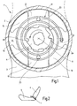
- the first embodiment relates to a locking fitting 1 of a vehicle seat for a motor vehicle, which includes a fitting upper part, hereinafter referred to as the first fitting part 2, and a fitting lower part, hereinafter referred to as a second fitting part 3 comprises.
- a detent fitting 1 On the two sides of the vehicle seat each a detent fitting 1 is arranged.
- the backrest 4 attached to the first fitting part 2 is attached by means of the two locking fittings 1 on the seat part 5 of the vehicle seat.
- the two locking fittings 1 are interconnected by a transmission rod, not shown.
- the first fitting part 2 has on its side facing the second fitting part 3 inside a cylindrical recess which defines a space 8 between the two fitting parts 2 and 3.
- An eccentric 11 in the form of a circular disc with two point-symmetrical pairs of two cams on the outer circumference is seated within the installation space 8 on a driver, not shown, the again rotatably seated on the transmission rod, so that the eccentric 11 is rotatable about a central axis A.
- latch 13 In the same plane as the eccentric 11, but with a greater radial distance from the axis A, two flat tooth segments, hereinafter referred to as latch 13, are arranged within the installation space 8, which is offset by 180 ° (ie point-symmetrical to each other) movable in the radial direction are.
- Each latch 13 carries at its radially outer end on its edge a toothing for cooperation with the ring gear 10 and is provided at its radially inner end at the edge with a saunockigen contour, which with the eccentric acting as a control 11 interacts.
- the extending in the radial direction of the edge surfaces of the bolt 13 are parallel to each other over most of their length.
- the second fitting part 3 has a projecting into the space 8 guide 15 for lying in the same plane latch 13.
- the guide 15 consists of four mirror-symmetrically arranged segments, which form in pairs a channel for each bar 13, which abuts with its parallel edge surfaces on the side walls of the channel.
- the guide 15 also serves to support the first fitting part 2 on the second fitting part 3, i. the first fitting part 2 sits with its ring gear 10 on the cylindrically curved outer side of the four segments.
- the outer spring end 17 'of the single spring 17 is clamped on the second fitting part 3, clipped or otherwise secured.
- the spring 17 is preferably installed with bias so that the spring 17 acts on the eccentric 11 and rotates about the axis A that its cams on the contour of the latch 13 radially outwardly press into the sprocket 10, ie the eccentric with bias 11 is applied in the direction of rotation in the clockwise direction in the drawing.
- the locking fitting 1 is locked so.
- the eccentric 11 is rotated by the transmission rod about the axis A counterclockwise, i. externally applied, which is indicated in the drawing by a curved arrow, he pulls the spring 17 together.
- a non-illustrated, non-rotatably seated on the eccentric 11 control disk is rotated, which has scenes for the lugs 23.
- the lugs 23 are acted upon by the spring 17 - and optionally by the control disk - in the radial direction inwardly, whereby the bolt 13 are pulled radially inward.
- the locking fitting 1 is thus unlocked, so that the backrest 4 is pivotable relative to the seat part 5.
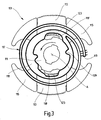
- the second embodiment is similar to the first embodiment, as far as not described below, which is why the same and equivalent components bear 100 higher reference numerals.
- the bolt 113 which are guided in the guide 115, radially outward.
- the eccentric 117 acted upon, spirally formed, single spring 117 is provided, which surrounds the axis A.
- the outer end 117 ' is in turn attached to the second fitting part.
- the spring 117 continues in one piece in an inner ring 118, which on the one hand engages in corresponding receptacles of the eccentric 11 by means of projections 117 and on the other hand has two switching contours 118.
- Each switching contour 118 ' is arranged radially outside a cam 123, which is pronounced from the latch 113.
- the spring 117 is contracted, pulling the latch 113 by means of the switching contour 118 'and the cam 123 radially inwardly to to unlock the catch fitting.
Description
Die Erfindung betrifft einen Rastbeschlag für einen Fahrzeugsitz, insbesondere für einen Kraftfahrzeugsitz, mit den Merkmalen des Oberbegriffs des Anspruches 1.The invention relates to a catch fitting for a vehicle seat, in particular for a motor vehicle seat, with the features of the preamble of claim 1.
Aus der
Der Erfindung liegt die Aufgabe zu Grunde, einen Rastbeschlag der eingangs genannten Art zu verbessern, insbesondere die Anzahl der Bauteile zu reduzieren. Diese Aufgabe wird erfindungsgemäß durch einen Rastbeschlag mit den Merkmalen des Anspruches 1 gelöst. Vorteilhafte Ausgestaltungen sind Gegenstand der Unteransprüche.The invention is based on the object to improve a locking fitting of the type mentioned, in particular to reduce the number of components. This object is achieved by a catch fitting with the features of claim 1. Advantageous embodiments are the subject of the dependent claims.
Die Feder umrundet die Achse, d.h. überstreicht nahezu den gesamten Bauraum, der zwischen den Beschlagteilen definiert ist und innerhalb dessen die für die Verriegelung des Rastbeschlags notwendigen Bauteile angeordnet sind, beispielsweise der Exzenter, die vorgesehenen Riegel und auch die Feder. Dadurch besteht zum einen die Möglichkeit, für die Hauptaufgabe der Feder, d.h. das Beaufschlagen des Exzenters, eine einzige Feder vorzusehen, die den Exzenter wenigstens näherungsweise symmetrisch beaufschlagen kann. Dies reduziert die Anzahl der notwendigen Bauteile. Dabei ist die Feder vorzugsweise an dem die vorgesehenen Riegel führenden zweiten Beschlagteil abgestützt. Zum anderen kann die Feder eine weitere Aufgaben wahrnehmen, nämlich die Riegel nach innen ziehen, was ebenfalls die Anzahl der notwendigen Bauteile reduziert, also die Herstellungskosten verringert und den Einbau erleichtert.The spring orbits the axis, ie covers almost the entire space, which is defined between the fitting parts and within which are arranged for the locking of the detent fitting components are arranged, for example, the eccentric, the bolt provided and the spring. As a result, on the one hand, it is possible to provide for the main task of the spring, ie the application of the eccentric, a single spring which can act on the eccentric at least approximately symmetrically. This reduces the number of necessary components. In this case, the spring is preferably supported on the second bolt part leading the intended bolt. On the other hand, the spring can perform a further task, namely pull the bolt inward, which also reduces the number of necessary components, thus reducing the cost and facilitates installation.
In einer erfindungsgemäßen Anordnung der Bauteile des Rastbeschlags sind der Exzenter radial innen und die vorgesehenen Riegel, in der Regel zwei, radial außen angeordnet. Der von der vorzugsweise vorgespannten Feder beaufschlagte Exzenter drückt die vorgesehenen Riegel zum Zusammenwirken mit dem ersten Beschlagteil radial nach außen, so dass der Rastbeschlag verriegelt. Zum Entriegeln sind die Riegel radial nach innen zu ziehen. Hierfür weist jeder vorgesehene Riegel eine Nase, einen Nocken, einen Vorsprung oder dergleichen auf, die bzw. der beispielsweise aus dem Material des Riegels herausgedrückt ist. Dabei ist die Feder mit wenigstens einer Windung oder einer Schaltkontur radial außerhalb derselben bzw. desselben angeordnet, so dass sie bei einer Bewegung radial nach innen den Riegel mitnehmen kann.In an inventive arrangement of the components of the detent fitting of the eccentric are radially inside and the proposed bolt, usually two, arranged radially outward. The acted upon by the preferably preloaded spring eccentric pushes the bolt provided for cooperation with the first fitting part radially outwards, so that the latching fitting locks. To unlock, the bolts are to be pulled radially inwards. For this purpose, each bolt provided on a nose, a cam, a projection or the like, which is or for example pressed out of the material of the bolt. In this case, the spring with at least one turn or a switching contour is arranged radially outside the same or the same, so that they can take the bolt with a movement radially inwardly.
Wenn der Exzenter extern beaufschlagt wird, beispielsweise durch eine im Bereich der Achse angreifende Welle oder dergleichen, wird die Feder zusammengezogen, beispielsweise indem die Feder innen am Exzenter und außen beschlagteilfest angebracht ist. Die sich zusammenziehende Feder zieht dann die vorgesehenen Riegel an ihrer Nase, Nocken, Vorsprung oder dergleichen radial nach innen, beispielsweise direkt mittels der Windung oder mittels einer Schaltkontur.When the eccentric is applied externally, for example by a shaft acting in the region of the shaft or the like, the spring is contracted, for example, by the spring is mounted inside the eccentric and outside the fitting part. The contracting spring then pulls the provided latch on its nose, cam, projection or the like radially inward, for example, directly by means of the winding or by means of a switching contour.
Die Feder sitzt innen vorzugsweise formschlüssig auf dem Exzenter, um eine gute Mitnahme zu gewährleisten. Dies kann durch Vorsprünge und/oder Aufnahmen verwirklicht sein, auch am inneren Ende der Feder. An die Feder kann auch innen ein Innenring angeformt sein, welcher auf dem Exzenter sitzt und diesen ringförmig umschließt. Auch hier sind vorzugsweise Vorsprünge und/oder Aufnahmen zur Bildung des Formschlusses vorgesehen.The spring sits inside preferably positive fit on the eccentric to ensure a good entrainment. This can be realized by projections and / or receptacles, also at the inner end of the spring. On the spring, an inner ring can be formed on the inside, which sits on the eccentric and surrounds this ring. Again, preferably projections and / or receptacles are provided to form the positive connection.
Die Feder ist vorzugsweise aus einem dünnen Federstahlblech spiralförmig ausgestanzt, so daß zugleich die Vorsprünge und/oder Aufnahmen ausgebildet und durch eine Geometrieabweichung zum späteren Einbauzustand eine Vorspannung aufgeprägt werden kann.The spring is preferably spirally punched out of a thin spring steel sheet, so that at the same time formed the projections and / or recordings and can be impressed by a geometry deviation for later installation state, a bias.
Ein erfindungsgemäßer Fahrzeugsitz weist wenigstens einen, vorzugsweise zwei der erfindungsgemäßen Rastbeschläge auf, die beispielsweise mittels einer Übertragungsstange miteinander verbunden sind.An inventive vehicle seat has at least one, preferably two of the latching fittings according to the invention, which are connected to each other for example by means of a transmission rod.
Im folgenden ist die Erfindung anhand zweier in der Zeichnung dargestellter Ausführungsbeispiele näher erläutert. Es zeigen
- Fig. 1
- einen Schnitt durch das erste Ausführungsbeispiel,
- Fig. 2
- eine schematische Teilansicht eines erfindungsgemäßen Fahrzeugsitzes, und
- Fig. 3
- einen Schnitt durch Teile des zweiten Ausführungsbeispiels.
- Fig. 1
- a section through the first embodiment,
- Fig. 2
- a schematic partial view of a vehicle seat according to the invention, and
- Fig. 3
- a section through parts of the second embodiment.
Das erste Ausführungsbeispiel betrifft einen Rastbeschlag 1 eines Fahrzeugsitzes für ein Kraftfahrzeug, der ein Beschlagoberteil, im folgenden als erstes Beschlagteil 2 bezeichnet, und ein Beschlagunterteil, im folgenden als zweites Beschlagteil 3 bezeichnet, umfaßt. Auf den beiden Seiten des Fahrzeugsitzes ist je ein Rastbeschlag 1 angeordnet. Die am ersten Beschlagteil 2 befestigte Lehne 4 ist mittels der beiden Rastbeschläge 1 am Sitzteil 5 des Fahrzeugsitzes angebracht. Die beiden Rastbeschläge 1 sind durch eine nicht näher dargestellte Übertragungsstange miteinander verbunden. Für diese und alle nachfolgend nicht näher beschriebenen Einzelheiten wird auf die
Das erste Beschlagteil 2 weist auf seiner dem zweiten Beschlagteil 3 zugewandten Innenseite eine zylindrische Vertiefung auf, welche einen Bauraum 8 zwischen beiden Beschlagteilen 2 und 3 definiert. Die im ersten Beschlagteil 2 ausgebildete, in Umfangsrichtung verlaufende Begrenzungsfläche des Bauraumes 8 trägt einen Zahnkranz 10. Ein Exzenter 11 in Form einer kreisförmigen Scheibe mit zwei punktsymmetrischen Paaren von je zwei Nocken am Außenumfang sitzt innerhalb des Bauraumes 8 auf einem nicht näher dargestellten Mitnehmer, der wiederum drehfest auf der Übertragungsstange sitzt, so daß der Exzenter 11 um eine zentrale Achse A drehbar ist.The first fitting
In der gleichen Ebene wie der Exzenter 11, aber mit größerem radialen Abstand zur Achse A, sind zwei flache Zahnsegmente, im folgenden als Riegel 13 bezeichnet, innerhalb des Bauraumes 8 angeordnet, die um 180° versetzt (d.h. punktsymmetrisch zueinander) in radialer Richtung beweglich sind. Jeder Riegel 13 trägt an seinem radial äußeren Ende auf seinem Rand eine Verzahnung zum Zusammenwirken mit dem Zahnkranz 10 und ist an seinem radial inneren Ende am Rand mit einer zweinockigen Kontur versehen, welche mit dem als Steuerelement wirkenden Exzenter 11 zusammenwirkt. Die in radialer Richtung verlaufenden Randflächen der Riegel 13 sind über den größten Teil ihrer Länge hinweg parallel zueinander.In the same plane as the eccentric 11, but with a greater radial distance from the axis A, two flat tooth segments, hereinafter referred to as
Das zweites Beschlagteil 3 weist eine in den Bauraum 8 vorspringende Führung 15 für die in der gleichen Ebene liegenden Riegel 13 auf. Die Führung 15 besteht aus vier spiegelsymmetrisch zueinander angeordneten Segmenten, die paarweise einen Kanal für jeweils einen Riegel 13 bilden, welcher mit seinen parallelen Randflächen an den Seitenwänden des Kanals anliegt. Die Führung 15 dient zugleich der Lagerung des ersten Beschlagteils 2 auf dem zweiten Beschlagteil 3, d.h. das erste Beschlagteil 2 sitzt mit seinem Zahnkranz 10 auf der zylindrisch gekrümmten Außenseite der vier Segmente.The second fitting
Eine Feder 17, welche aus einem dünnen Federstahlblech von etwa 1 mm Stärke spiralförmig ausgestanzt ist, ist innerhalb des Bauraumes 8 in einer Ebene zwischen derjenigen der Riegeln 13 und der Führung 15 einerseits und der am ersten Beschlagteil 2 vorgesehenen, stirnseitigen Begrenzungsfläche des Bauraums 8 angeordnet, wobei sie die Achse A umrundet. Das äußere Federende 17' der einzigen Feder 17 ist am zweiten Beschlagteil 3 eingeklemmt, eingeclipst oder anderweitig befestigt. Mehrere, radial nach innen weisende Vorsprünge 17" einschließlich eines solchen, der am inneren Federende 17"' vorgesehen ist, sitzen formschlüssig in Aufnahmen auf der Umfangsfläche des Exzenters 11 und können zusätzlich gesichert sein, so daß ein drehfester Sitz der Feder 17 auf dem Exzenter 11 gewährleistet ist. Zwischen den Windungen der Feder 17 sind zwei Nasen 23 angeordnet, von denen jede von einem der Riegel 13 in axialer Richtung absteht. Die Feder 17 ist vorzugsweise mit Vorspannung so eingebaut, daß ohne äußeren Einfluß die Feder 17 den Exzenter 11 so beaufschlagt und um die Achse A dreht, daß dessen Nocken über die Kontur die Riegel 13 radial nach außen in den Zahnkranz 10 drücken, d.h. der Exzenter 11 wird in der in der Zeichnung im Uhrzeigersinn liegenden Drehrichtung beaufschlagt. Der Rastbeschlag 1 ist damit verriegelt.A
Wird hingegen der Exzenter 11 mittels der Übertragungsstange um die Achse A gegen den Uhrzeigersinn gedreht, d.h. extern beaufschlagt, was in der Zeichnung durch einen gebogenen Pfeil angedeutet ist, zieht er die Feder 17 zusammen. Optional wird eine nicht näher dargestellte, drehfest auf dem Exzenter 11 sitzende Steuerscheibe gedreht, welche Kulissen für die Nasen 23 aufweist. Die Nasen 23 werden durch die Feder 17 - und optional durch die Steuerscheibe - in radialer Richtung nach innen beaufschlagt, wodurch die Riegel 13 radial nach innen gezogen werden. Der Rastbeschlag 1 ist damit entriegelt, so daß die Lehne 4 relativ zum Sitzteil 5 verschwenkbar ist.If, however, the eccentric 11 is rotated by the transmission rod about the axis A counterclockwise, i. externally applied, which is indicated in the drawing by a curved arrow, he pulls the
Das zweite Ausführungsbeispiel gleicht dem ersten Ausführungsbeispiel, soweit nachfolgend nicht abweichend beschrieben, weshalb gleiche und gleichwirkende Bauteile um 100 höhere Bezugszeichen tragen. Auch bei diesem Ausführungsbeispiel drückt im Falle ohne äußere Belastung der Exzenter 111 die Riegel 113, welche in der Führung 115 geführt sind, radial nach außen. Für diese Drehung des Exzenters 111 im Uhrzeigersinn ist wieder eine den Exzenter 117 beaufschlagende, spiralförmig ausgebildete, einzige Feder 117 vorgesehen, welche die Achse A umrundet. Das äußere Ende 117' ist wiederum am zweiten Beschlagteil angebracht. Am inneren Ende setzt sich die Feder 117 einstückig in einem Innenring 118 fort, welcher einerseits mittels Vorsprüngen 117" formschlüssig in entsprechende Aufnahmen des Exzenters 11 greift, und andererseits zwei Schaltkonturen 118' aufweist. Jede Schaltkontur 118' ist radial außerhalb eines Nockens 123 angeordnet, welcher aus dem Riegel 113 ausgeprägt ist. Wie im ersten Ausführungsbeispiel, wird bei einer extern eingeleiteten Drehung des Exzenters 111 entgegen dem Uhrzeigersinn die Feder 117 zusammengezogen, wobei sie die Riegel 113 mittels der Schaltkontur 118' und der Nocken 123 radial nach innen zieht, um den Rastbeschlag zu entriegeln.The second embodiment is similar to the first embodiment, as far as not described below, which is why the same and equivalent components bear 100 higher reference numerals. Also in this embodiment expresses in the case without external loading of the eccentric 111, the
- 1, 1011, 101
- RastbeschlagLocking device
- 22
- erstes Beschlagteilfirst fitting part
- 33
- zweites Beschlagteilsecond fitting part
- 44
- Lehnerest
- 55
- Sitzteilseat part
- 88th
- Bauraumspace
- 1010
- Zahnkranzsprocket
- 11, 11111, 111
- Exzentereccentric
- 13, 11313, 113
- Riegelbars
- 15, 11515, 115
- Führungguide
- 17, 11717, 117
- Federfeather
- 17', 117'17 ', 117'
- äußeres Federendeouter spring end
- 17", 117"17 ", 117"
- Vorsprunghead Start
- 17"'17 " '
- inneres Federendeinner spring end
- 2323
- Nasenose
- 118118
- Innenringinner ring
- 118'118 '
- Schaltkonturswitching contour
- 123123
- Nockencam
- AA
- Achseaxis
Claims (6)
- A detent fitting for a vehicle seat, in particular for a motor-vehicle seat, witha) a first fitting part (2),b) a second fitting part (3) which is movable relative to the first fitting part (2),c) at least one locking element (13; 113) which interacts with the first fitting part (2) and is guided by the second fitting part (3), wherein each locking element (13; 113) provided has a lug (23) or a cam (123) or the like which projects in an axial direction,d) an eccentric (11; 111) which acts on the locking element (13; 113) and is rotatable about an axis (A), wherein the eccentric (11; 111) is arranged radially inwardly and the locking elements (13; 113) provided are arranged radially outwardly,e) and at least one spiral-shaped spring (17; 117) which encircles the axis (A) and acts upon the eccentric (11; 111), wherein the eccentric (11; 111), when acted upon by the spring (17; 117), pushes the provided locking elements (13; 113) radially outwards so that they interact with the first fitting part (2) and, when acted upon externally, tightens the spring (17; 117), characterised in thatf) the spring (17; 117) has at least one coil or switching contour (118') arranged radially outside the lug (23) or the cam (123) or the like, andg) the tightening spring (17; 117) acts upon the lugs (23) or cams (123) of the provided locking elements (13; 113) in a radially inwards direction and thereby pulls the provided locking elements (13; 113) radially inwards.
- A detent fitting according to claim 1, characterised in that the spring (17; 117) is attached by its outer end (17'; 117') to the second fitting part (3).
- A detent fitting according to claim 1 or 2, characterised in that the inside of the spring (17; 117) sits in a form-fitting manner on the eccentric (11; 111).
- A detent fitting according to claim 3, characterised in that an inner ring (118) is integrally formed on the inside of the spring (117) and sits on the eccentric (111).
- A detent fitting according to any one of the preceding claims, characterised in that the spring (17; 117) is punched in the shape of a spiral out of a thin spring-steel sheet.
- A vehicle seat with a backrest (4) which can be adjusted in its inclination relative to a seat part (5), wherein at least one detent fitting according to any one of the preceding claims is used for adjusting the inclination.
Priority Applications (1)
| Application Number | Priority Date | Filing Date | Title |
|---|---|---|---|
| PL04820588T PL1687176T3 (en) | 2003-11-28 | 2004-11-12 | Detent fitting for a vehicle seat |
Applications Claiming Priority (2)
| Application Number | Priority Date | Filing Date | Title |
|---|---|---|---|
| DE10355820A DE10355820B3 (en) | 2003-11-28 | 2003-11-28 | Ratchet stop for autombile passenger seat has ratchet between relatively rotatable stop components acted on by rotatable spring-loaded eccentric |
| PCT/EP2004/012821 WO2005061270A1 (en) | 2003-11-28 | 2004-11-12 | Detent fitting for a vehicle seat |
Publications (2)
| Publication Number | Publication Date |
|---|---|
| EP1687176A1 EP1687176A1 (en) | 2006-08-09 |
| EP1687176B1 true EP1687176B1 (en) | 2008-05-07 |
Family
ID=34442347
Family Applications (1)
| Application Number | Title | Priority Date | Filing Date |
|---|---|---|---|
| EP04820588A Expired - Fee Related EP1687176B1 (en) | 2003-11-28 | 2004-11-12 | Detent fitting for a vehicle seat |
Country Status (8)
| Country | Link |
|---|---|
| US (1) | US7204555B2 (en) |
| EP (1) | EP1687176B1 (en) |
| JP (1) | JP4567003B2 (en) |
| KR (1) | KR101122934B1 (en) |
| CN (1) | CN100564099C (en) |
| DE (2) | DE10355820B3 (en) |
| PL (1) | PL1687176T3 (en) |
| WO (1) | WO2005061270A1 (en) |
Families Citing this family (22)
| Publication number | Priority date | Publication date | Assignee | Title |
|---|---|---|---|---|
| JP4883341B2 (en) * | 2005-08-24 | 2012-02-22 | アイシン精機株式会社 | Seat reclining device |
| US7246598B2 (en) * | 2005-11-02 | 2007-07-24 | Keihin Corporation | Accelerator pedal device |
| CN101378678B (en) * | 2006-02-16 | 2010-06-02 | 株式会社今仙电机制作所 | Reclining device |
| DE102007007362B4 (en) * | 2007-02-14 | 2009-07-09 | Faurecia Autositze Gmbh | adjustment |
| JP4308859B2 (en) * | 2007-02-20 | 2009-08-05 | 株式会社今仙電機製作所 | Reclining device |
| US7703852B2 (en) * | 2007-12-03 | 2010-04-27 | Lear Corporation | Heavy duty reclining mechanism for vehicle seats |
| WO2009091980A1 (en) | 2008-01-17 | 2009-07-23 | Fisher Dynamics Corporation | Round recliner mechanism |
| DE102008029438B4 (en) * | 2008-06-16 | 2014-05-22 | Keiper Gmbh & Co. Kg | Fitting for a vehicle seat |
| DE102009022777A1 (en) * | 2009-05-20 | 2010-11-25 | Brose Fahrzeugteile Gmbh & Co. Kommanditgesellschaft, Coburg | Locking device |
| DE102009041492A1 (en) * | 2009-09-10 | 2011-03-24 | Keiper Gmbh & Co. Kg | Fitting for vehicle seat, particularly for motor vehicle seat, has two fitting components which are rotatable around axis relative to each other, and spring arrangement |
| DE102011106285B4 (en) * | 2011-07-04 | 2013-08-22 | Keiper Gmbh & Co. Kg | Fitting system for a vehicle seat and vehicle seat |
| US9296315B2 (en) | 2013-02-26 | 2016-03-29 | Fisher & Company, Incorporated | Recliner mechanism with backdriving feature |
| CN103241145B (en) * | 2013-05-23 | 2016-03-30 | 烟台延锋江森座椅有限责任公司 | A kind of contraction type spring Detent fitting for seat angle adjustor |
| US9902297B2 (en) | 2014-06-11 | 2018-02-27 | Fisher & Company, Incorporated | Latch mechanism with locking feature |
| DE102015215367B4 (en) * | 2015-03-13 | 2020-12-17 | Adient Luxembourg Holding S.À R.L. | Hardware system for a vehicle seat and vehicle seat |
| JP6682300B2 (en) * | 2016-03-04 | 2020-04-15 | シロキ工業株式会社 | Seat reclining device |
| DE102016215806B4 (en) * | 2016-08-23 | 2024-01-04 | Volkswagen Aktiengesellschaft | Backrest arrangement for a motor vehicle and motor vehicle |
| DE102016225834B4 (en) * | 2016-10-04 | 2020-01-09 | Adient Luxembourg Holding S.À R.L. | VEHICLE SEAT, IN PARTICULAR MOTOR VEHICLE SEAT |
| US10076978B2 (en) * | 2016-10-20 | 2018-09-18 | Ford Global Technologies, Llc | Power lift and recliner release/fold device |
| CN107668995A (en) * | 2017-10-06 | 2018-02-09 | 中山市东立家具配件有限公司 | A kind of inclination controller of office chair |
| KR102001508B1 (en) | 2017-12-26 | 2019-07-18 | 현대트랜시스(주) | Seat recliner for vehicle |
| US11726519B2 (en) | 2021-12-17 | 2023-08-15 | Raytheon Company | Clocking spring for a rotatable shaft |
Family Cites Families (19)
| Publication number | Priority date | Publication date | Assignee | Title |
|---|---|---|---|---|
| DE2641582A1 (en) * | 1976-09-16 | 1978-03-23 | Keiper Automobiltechnik Gmbh | HINGED FITTING FOR VEHICLE SEATS WITH BACKREST SWIVELING IN RELATION TO THE SEAT PART |
| US4082352A (en) * | 1977-01-13 | 1978-04-04 | Lear Siegler, Inc. | Seat back recliner |
| JP4265024B2 (en) * | 1998-06-22 | 2009-05-20 | トヨタ紡織株式会社 | Reclining device |
| AU4766199A (en) * | 1998-07-28 | 2000-02-21 | Magna Interior Systems Inc. | A recliner assembly |
| JP2000192992A (en) * | 1998-12-25 | 2000-07-11 | Toyota Autom Loom Works Ltd | Motive power transmitting mechanism |
| DE19904300C1 (en) * | 1999-01-28 | 2000-08-03 | Keiper Gmbh & Co | Ratchet fitting for a vehicle seat has a guide for the bolt which also acts as the mounting for the upper and lower sections with a toothed segment at the bolt engaging a rim gear at the limit surface |
| JP4374657B2 (en) * | 1999-06-08 | 2009-12-02 | アイシン精機株式会社 | Seat reclining device |
| DE60043584D1 (en) * | 1999-06-16 | 2010-02-04 | Nhk Spring Co Ltd | reclining |
| US6312053B1 (en) * | 1999-07-20 | 2001-11-06 | Magna Interior Systems, Inc. | Recliner assembly |
| JP4457434B2 (en) * | 1999-08-02 | 2010-04-28 | トヨタ紡織株式会社 | Reclining device |
| FR2801850B1 (en) * | 2000-11-10 | 2004-01-16 | Faurecia Sieges Automobile | ARTICULATION MECHANISM FOR VEHICLE SEAT AND SEAT PROVIDED WITH SUCH A MECHANISM |
| JP2002327666A (en) * | 2001-03-01 | 2002-11-15 | Starting Ind Co Ltd | Starter device |
| DE10217873B4 (en) * | 2001-04-23 | 2008-08-14 | Aisin Seiki K.K., Kariya | joint fitting |
| JP4595256B2 (en) * | 2001-06-26 | 2010-12-08 | アイシン精機株式会社 | Seat reclining device |
| WO2003022622A1 (en) * | 2001-09-06 | 2003-03-20 | Keiper Gmbh & Co. | Fitting for a vehicle seat |
| KR100446127B1 (en) * | 2002-03-14 | 2004-08-30 | 주식회사다스 | Reclining device of seat for vehicle |
| JP4032806B2 (en) | 2002-04-18 | 2008-01-16 | トヨタ紡織株式会社 | Reclining device |
| JP3991780B2 (en) * | 2002-06-19 | 2007-10-17 | アイシン精機株式会社 | Seat reclining device |
| US6883869B2 (en) * | 2003-03-10 | 2005-04-26 | Porter Group, Llc | Vehicle seat back recliner |
-
2003
- 2003-11-28 DE DE10355820A patent/DE10355820B3/en not_active Expired - Fee Related
-
2004
- 2004-11-12 WO PCT/EP2004/012821 patent/WO2005061270A1/en active IP Right Grant
- 2004-11-12 DE DE502004007088T patent/DE502004007088D1/en active Active
- 2004-11-12 EP EP04820588A patent/EP1687176B1/en not_active Expired - Fee Related
- 2004-11-12 JP JP2006540262A patent/JP4567003B2/en not_active Expired - Fee Related
- 2004-11-12 KR KR1020057016006A patent/KR101122934B1/en not_active IP Right Cessation
- 2004-11-12 CN CNB2004800086384A patent/CN100564099C/en not_active Expired - Fee Related
- 2004-11-12 PL PL04820588T patent/PL1687176T3/en unknown
-
2006
- 2006-04-26 US US11/411,719 patent/US7204555B2/en not_active Expired - Fee Related
Also Published As
| Publication number | Publication date |
|---|---|
| US20060185466A1 (en) | 2006-08-24 |
| KR101122934B1 (en) | 2012-03-20 |
| EP1687176A1 (en) | 2006-08-09 |
| CN1767967A (en) | 2006-05-03 |
| CN100564099C (en) | 2009-12-02 |
| WO2005061270A1 (en) | 2005-07-07 |
| PL1687176T3 (en) | 2008-10-31 |
| US7204555B2 (en) | 2007-04-17 |
| KR20060112196A (en) | 2006-10-31 |
| DE10355820B3 (en) | 2005-05-19 |
| JP2007512173A (en) | 2007-05-17 |
| DE502004007088D1 (en) | 2008-06-19 |
| JP4567003B2 (en) | 2010-10-20 |
Similar Documents
| Publication | Publication Date | Title |
|---|---|---|
| EP1687176B1 (en) | Detent fitting for a vehicle seat | |
| DE102005054490B4 (en) | Fitting for a vehicle seat | |
| EP1799499B1 (en) | Fitting for a vehicle seat | |
| DE19904299C1 (en) | Locking fitting for vehicle seat, with transmission element in form of axial lock to hold fitting parts together | |
| EP2566719B1 (en) | Fitting for a vehicle seat | |
| EP1768870B1 (en) | Fitting for a vehicle seat | |
| EP1592577B1 (en) | Geared fitting for a vehicle seat | |
| DE102005026658B3 (en) | Inclination adjustment fitting for vehicle seat, has contact cam serving for load transmission, over larger contact surface of cam, from fitting part connected with backrest onto another fitting part connected with seat part | |
| EP1720729B1 (en) | Fitting for a motor vehicle seat | |
| DE102009041492A1 (en) | Fitting for vehicle seat, particularly for motor vehicle seat, has two fitting components which are rotatable around axis relative to each other, and spring arrangement | |
| DE102011015139B4 (en) | Adjusting mechanism with a fastening feature | |
| EP1560729A1 (en) | Fitting for a vehicle seat | |
| EP2001706A1 (en) | Fitting for a vehicle seat | |
| EP2802481B1 (en) | Fitting for a vehicle seat and vehicle seat | |
| DE10003305C1 (en) | Seat adjustment device for automobile passenger seat has threaded spindle for spindle drive secured between holding element and cooperating cover to prevent its relative rotation | |
| WO2010133538A1 (en) | Detent fitting comprising a spacer ring | |
| EP2525995B1 (en) | Fitting system for a vehicle seat | |
| DE102008017019A1 (en) | Articulated fitting for motor vehicle seats and with a round plate | |
| DE102010038797B4 (en) | Swivel fitting with a spring element prestressing two eccentric elements | |
| WO2021083830A1 (en) | Vehicle seat with differently sized swivel fittings | |
| DE102010039066B4 (en) | Fitting arrangement with a stop | |
| DE10021403A1 (en) | Inclination adjustment fitting for backrest of motor vehicle seats has seat-mounted and backrest-mounted parts with polygonal sections held in similarly shaped recesses | |
| DE102009002478A1 (en) | Locking and locking device of an adjustment fitting | |
| EP2580086B1 (en) | Fitting for a vehicle seat | |
| DE19921810B4 (en) | Locking fitting for a vehicle seat |
Legal Events
| Date | Code | Title | Description |
|---|---|---|---|
| PUAI | Public reference made under article 153(3) epc to a published international application that has entered the european phase |
Free format text: ORIGINAL CODE: 0009012 |
|
| 17P | Request for examination filed |
Effective date: 20050720 |
|
| AK | Designated contracting states |
Kind code of ref document: A1 Designated state(s): DE FR GB PL |
|
| DAX | Request for extension of the european patent (deleted) | ||
| RBV | Designated contracting states (corrected) |
Designated state(s): DE FR GB PL |
|
| 17Q | First examination report despatched |
Effective date: 20071005 |
|
| GRAP | Despatch of communication of intention to grant a patent |
Free format text: ORIGINAL CODE: EPIDOSNIGR1 |
|
| GRAS | Grant fee paid |
Free format text: ORIGINAL CODE: EPIDOSNIGR3 |
|
| GRAA | (expected) grant |
Free format text: ORIGINAL CODE: 0009210 |
|
| AK | Designated contracting states |
Kind code of ref document: B1 Designated state(s): DE FR GB PL |
|
| REG | Reference to a national code |
Ref country code: GB Ref legal event code: FG4D Free format text: NOT ENGLISH |
|
| REF | Corresponds to: |
Ref document number: 502004007088 Country of ref document: DE Date of ref document: 20080619 Kind code of ref document: P |
|
| REG | Reference to a national code |
Ref country code: PL Ref legal event code: T3 |
|
| PLBE | No opposition filed within time limit |
Free format text: ORIGINAL CODE: 0009261 |
|
| STAA | Information on the status of an ep patent application or granted ep patent |
Free format text: STATUS: NO OPPOSITION FILED WITHIN TIME LIMIT |
|
| 26N | No opposition filed |
Effective date: 20090210 |
|
| PGFP | Annual fee paid to national office [announced via postgrant information from national office to epo] |
Ref country code: FR Payment date: 20101109 Year of fee payment: 7 |
|
| PGFP | Annual fee paid to national office [announced via postgrant information from national office to epo] |
Ref country code: PL Payment date: 20101105 Year of fee payment: 7 |
|
| PGFP | Annual fee paid to national office [announced via postgrant information from national office to epo] |
Ref country code: GB Payment date: 20101022 Year of fee payment: 7 |
|
| REG | Reference to a national code |
Ref country code: DE Ref legal event code: R082 Ref document number: 502004007088 Country of ref document: DE |
|
| GBPC | Gb: european patent ceased through non-payment of renewal fee |
Effective date: 20111112 |
|
| REG | Reference to a national code |
Ref country code: FR Ref legal event code: ST Effective date: 20120731 |
|
| PG25 | Lapsed in a contracting state [announced via postgrant information from national office to epo] |
Ref country code: GB Free format text: LAPSE BECAUSE OF NON-PAYMENT OF DUE FEES Effective date: 20111112 |
|
| PG25 | Lapsed in a contracting state [announced via postgrant information from national office to epo] |
Ref country code: FR Free format text: LAPSE BECAUSE OF NON-PAYMENT OF DUE FEES Effective date: 20111130 |
|
| PGFP | Annual fee paid to national office [announced via postgrant information from national office to epo] |
Ref country code: DE Payment date: 20121130 Year of fee payment: 9 |
|
| PG25 | Lapsed in a contracting state [announced via postgrant information from national office to epo] |
Ref country code: PL Free format text: LAPSE BECAUSE OF NON-PAYMENT OF DUE FEES Effective date: 20111112 |
|
| REG | Reference to a national code |
Ref country code: PL Ref legal event code: LAPE |
|
| PG25 | Lapsed in a contracting state [announced via postgrant information from national office to epo] |
Ref country code: DE Free format text: LAPSE BECAUSE OF NON-PAYMENT OF DUE FEES Effective date: 20140603 |
|
| REG | Reference to a national code |
Ref country code: DE Ref legal event code: R119 Ref document number: 502004007088 Country of ref document: DE Effective date: 20140603 |