EP1596395A2 - Vorrichtung und Verfahren zur Signalpegelanpassung - Google Patents
Vorrichtung und Verfahren zur Signalpegelanpassung Download PDFInfo
- Publication number
- EP1596395A2 EP1596395A2 EP05103750A EP05103750A EP1596395A2 EP 1596395 A2 EP1596395 A2 EP 1596395A2 EP 05103750 A EP05103750 A EP 05103750A EP 05103750 A EP05103750 A EP 05103750A EP 1596395 A2 EP1596395 A2 EP 1596395A2
- Authority
- EP
- European Patent Office
- Prior art keywords
- fade
- crossfade
- channel
- channels
- mode
- Prior art date
- Legal status (The legal status is an assumption and is not a legal conclusion. Google has not performed a legal analysis and makes no representation as to the accuracy of the status listed.)
- Ceased
Links
Images




Classifications
-
- G—PHYSICS
- G11—INFORMATION STORAGE
- G11B—INFORMATION STORAGE BASED ON RELATIVE MOVEMENT BETWEEN RECORD CARRIER AND TRANSDUCER
- G11B27/00—Editing; Indexing; Addressing; Timing or synchronising; Monitoring; Measuring tape travel
- G11B27/02—Editing, e.g. varying the order of information signals recorded on, or reproduced from, record carriers
- G11B27/031—Electronic editing of digitised analogue information signals, e.g. audio or video signals
- G11B27/038—Cross-faders therefor
Definitions
- the present invention relates to signal level adjustment apparatus and control methods therefor which are suitable for use in production of video/audio content, as well as computer programs related to such signal level adjustment.
- the present invention concerns a mixer, video switcher or the like for processing audio signals and/or video signals.
- a crossfade process is generally performed for fading-in the audio signal of one of the channels while fading-out the audio signal of the other channel.
- the above-mentioned control apparatus can also instruct a digital mixer to perform the crossfade process. Namely, once the human operator performs predetermined operation on the control apparatus, a command instructing a cross-face process (i.e., crossfade execution instruction) is transmitted from the control apparatus to the digital mixer. Upon receipt of the crossfade-instructing command, the digital mixer carries out the instructed crossfade process on the basis of prestored crossfade setting information.
- audio signals of a group of input channels are faded out while audio signals of another group of input channels are faded in.
- faders corresponding to the various channels are automatically driven in an upward/downward direction on an operation panel of the digital mixer.
- Such a digital mixer that can be remote-controlled from outside is disclosed, for example, in "DM2000 Instruction Manual", published by Hyundai Corporation in February, 2002.
- the above-discussed technique can not cease the crossfade only for a certain one or ones of the channels via the operation panel of the digital mixer.
- the human operator desires to cease the crossfade for only a certain one or ones of the channels, he or she may, in some cases, want the corresponding faders to be restored to their respective states or positions before execution of the crossfade, or, in other cases, want the corresponding faders to be stopped at desired positions after the start of the crossfade execution.
- an improved signal level adjustment apparatus which comprises: at least two level adjusting operators each operable manually or automatically to adjust a signal level of any one of at least two channels; a setting section that, for each of the channels, sets a fade operation mode of the channel to either a first mode where a fade is enabled or a second mode where the fade is disabled; a crossfade execution section that, upon receipt of a crossfade execution instruction, automatically operates a corresponding one of the operators in such a manner that the signal level is faded in or faded out for each channel set in the first mode from among the at least two channels; and a change section that, when the fade operation mode for any one of the channels has been changed to the second mode while a fade-in or fade-out process is being executed for the one channel by the crossfade execution section, ceases the fade-in or fade-out process for the one channel and changes an operating position or state of the operator for the one channel to a predetermined state.
- the fade operation mode of each of the channels can be set, via the setting section, to either the first mode where the fade is enabled or the second mode where the fade is disabled.
- the setting section changing the fade operation mode from the first mode (i.e., fader-ON mode) to the second mode (i.e., fader-OFF mode) while the fade-in or fade-out process is being executed for a desired one of the channels, the crossfade process being executed for the desired channel can be ceased along its way.
- the fade operation mode for a given channel has been set to the second mode (i.e., fader-OFF mode)
- no fade operation is executed for the given channel even when a new crossfade execution instruction is received later.
- the fade operation mode for the given channel has been changed from the second mode to the first mode (i.e., fader-ON mode)
- the fade-in or fade-on process will be carried out in response to reception of a subsequent, new crossfade execution instruction.
- the above-mentioned "predetermined state” is an operating position or state of the operator immediately before the start of the fade-in or fade-out process.
- the change section restores the operating state of the operator for the channel in question to the operating state of the operator immediately before the start of the fade-in or fade-out process.
- the signal level adjustment apparatus of the present invention may further comprise an information presentation section that, for each of the channels, presents crossfade mode information indicating which one of the fade-in and fade-out is to be executed; and an informing device that informs or indicates the fade operation mode and crossfade mode information of each of the channels.
- an information presentation section that, for each of the channels, presents crossfade mode information indicating which one of the fade-in and fade-out is to be executed
- an informing device that informs or indicates the fade operation mode and crossfade mode information of each of the channels.
- an improved signal level adjustment apparatus which comprises: a plurality of level adjusting operators each operable manually or automatically to adjust a signal level of any one of a plurality of channels; a crossfade execution section that, upon receipt of a crossfade execution instruction, automatically operates a corresponding one of the operators in such a manner that the signal level of one of at least two channels among the plurality of channels is faded in and the signal level of other of the at least two channels is faded out; a detection section that detects whether a predetermined crossfade cease instruction has been given for any one of the channels while a fade-in or fade-out process is being executed for the one channel by the crossfade execution section; and a cease control section that, when the crossfade cease instruction for the one channel has been detected by the detection section, ceases the fade-in or fade-out process for the one channel while keeping the operator for the one channel in a current operating state.
- the channel in question can resume the fade-in or fade-out process upon receipt of a new crossfade execution instruction.
- the detection section detects that the predetermined crossfade cease instruction has been given, on the basis of a detection of manual operation of the operator for the one channel while the fade-in or fade-out process is being executed for the one channel by the crossfade execution section, and the operator for the one channel is shifted from the current operating state, where the operator has been kept by the cease control section, to an operating state corresponding to the manual operation of the operator.
- the crossfade execution section may be arranged as follows. Namely, concerning any one of the channels for which the predetermined crossfade cease instruction has been given, the crossfade execution section executes the fade-in or fade-out process when a new crossfade execution instruction is given later.
- the crossfade execution section does not execute the fade-in or fade-out process even when a crossfade execution instruction is given, until the crossfade inhibition is canceled later.
- an operating amount of a corresponding tone volume operator should be set to a predetermined reference operating amount can be selected by the user selecting any one of the crossfade cease operation and crossfade inhibition operation, with the result that the present invention can cease the crossfade process in any of a variety of different manners.
- the present invention may be constructed and implemented not only as the apparatus invention as discussed above but also as a method invention. Also, the present invention may be arranged and implemented as a software program for execution by a processor such as a computer or DSP, as well as a storage medium storing such a software program. Further, the processor used in the present invention may comprise a dedicated processor with dedicated logic built in hardware, not to mention a computer or other general-purpose type processor capable of running a desired software program.
- reference numerals 106, 108 and 110 represent video tape recorders, of which the video tape recorders 106 and 108 reproduce video/audio signals that are materials for producing content.
- the video tape recorder 110 records video/audio signals of completed content.
- Each of the video tape recorders 106, 108 and 110 is capable of recording and reproducing audio signals of a multiplicity of tracks.
- 104 represents a video device that comprises a video switcher, video effector, etc., and the video device 104 performs effect impartment, mixing, switching and other processes on video signals reproduced via the video tape recorders 106 and 108.
- the thus-processed video signals are supplied from the video device 104 to the video tape recorder 110.
- the digital mixer 112 of the present invention performs effect processing, level adjustment processing, etc. on audio signals supplied from the video tape recorders 106 and 108, and it supplies the thus-processed audio signals to the video tape recorder 110.
- Control apparatus 102 remote-controls a plurality of devices, such as the video tape recorders 106, 108 and 110 and digital mixer 112, to operate in appropriately timed relation to one another, and the control apparatus 102 transmits, to each of the to-be-controlled devices, an instruction (i.e., control command), indicative of specific control (i.e., process to be performed by the device), in accordance with predetermined control timing specific to the device (i.e., at timing when the device should perform the instructed process).
- an instruction i.e., control command
- indicative of specific control i.e., process to be performed by the device
- predetermined control timing specific to the device i.e., at timing when the device should perform the instructed process.
- each of the to-be-controlled devices Upon receipt of such a control command from the control apparatus 102, each of the to-be-controlled devices (such as the video tape recorders 106, 108 and 110 and digital mixer 112) carries out the process indicated by the control command.
- Sound system 114 audibly generates or sounds each CUE signal (monitoring signal) output from the digital mixer 112.
- reference numeral 2 represents a control signal interface (I/F), via which control signals, such as the above-mentioned commands, are input and output from and to (i.e., communicated with) the control apparatus 102.
- Audio signal interface (I/F) 4 communicates audio signals with input/output devices, such as the video tape recorders 106, 108 and 110.
- Signal processing circuit 6, which comprises a group of DSPs (Digital Signal Processors), performs mixing processing and effect processing on digital audio signals supplied via the audio signal interface 4 and outputs the processed results to the audio signal interface 4.
- DSPs Digital Signal Processors
- reference numeral 10 represents a group of operators, which includes faders, volume control operators, switches, character-entering keyboard, mouse, etc.
- Group of display devices and display members 12 includes a flat panel display (e.g., LCD), LEDs provided around the volume control operators, LEDs embedded or built in the switches and the like, level meters, etc.
- Reference numeral 18 represents a CPU, which controls various components, via a bus 8, on the basis of control programs stored in a ROM 14.
- RAM 16 is used as a working memory for the CPU 18 and for various other purposes.
- the RAM 16 includes a current area 16a, which is provided for storing currently-set values of individual parameters to be used for signal processing by the signal processing circuit 6.
- a current area 16a which is provided for storing currently-set values of individual parameters to be used for signal processing by the signal processing circuit 6.
- fader gains i.e., values for controlling tone volumes
- Signal processing to be performed by the signal processing circuit 6 on audio signals is controlled on the basis of the values stored in the current area 16a.
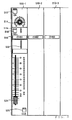
- reference numerals 510-1, 510-2, ... represent channel strips that are provided in corresponding relation to the input channels.
- the channel strips 510-1, 510-2, ... are constructed in the same manner, and thus the following paragraphs representatively describe a detailed construction of one of the channel strips 510-1.
- an ON key 512 switches between ON and OFF states of the corresponding input channel, and the ON key 512 has an LED built therein that is illuminated (i.e., turned on) or deilluminated (i.e., turned off) in response to an ON/OFF state of the key 512.
- Rotary encoder 514 is used for panning adjustment and gain adjustment of the corresponding input channel, and a plurality of LEDs are disposed around the rotary encoder 514 in a substantial annual configuration. Operating amount of the rotary encoder 514 is displayed by an illumination state of the LEDs.
- SEL key 516 switches between ON and OFF states of a later-described FADER mode.
- the SEL key 516 has built therein a plurality of LEDs of different illumination colors, and illumination/deillumination states of these LEDs 516a can be set independently of each other.
- Display 518 displays the name of the corresponding input channel.
- Electric fader 524 includes a detector for detecting manual operation thereof by the human operator. When human operator's manual operation of the fader 524 has been detected by the detector, the fader 524 detects an operating amount (level) of the fader 524 having been achieved by the manual operation and then adjusts the fader gain of the corresponding input channel in accordance with the detected level. Operating amounts of the rotary encoder 514 and electric fader 524 can be automatically set on the basis of instructions by the CPU 18.
- CUE key 526 switches between ON and OFF states of the CUE function of the corresponding input channel. Audio signal of each input channel, for which the CUE function is ON, is mixed with a CUE signal. Namely, a result of mixing between audio signals of one or more input channels becomes a CUE signal that is audibly generated via the sound system 114.
- Setting information table 30 of Fig. 4 is stored in advance in the RAM 16 of the digital mixer 112.
- reference numeral 32 represents a "channel number section” in which are indicated the unique numbers of the input channels in the digital mixer 112, and 34 represents an "input device allocation section".
- the input device allocation section 34 defines which input channels input audio signals of a plurality of input devices A. B, C, ... are allocated to. Those input channels, to which the input devices are allocated, are indicated by marks "X"..
- the input devices A. B, C, ... may be any desired devices
- the illustrated example of Fig. 4 assumes that the input device A is the video tape recorder 106 and the input device B is the video tape recorder 108. More specifically, in the illustrated example of Fig.
- "FADER mode designation section” 35 designates, for each of the input channels, "FADER MODE ON” or “FADER MODE OFF' as an FADER mode setting.
- the "FADER mode” designates, for each of the input channels, whether or not the internal elements in the channel strip 510-1, 510-2, ... of the input channel can be remote-controlled on the basis of a control command from the control apparatus 102. Namely, if the FADER mode is "ON" (i.e., FADER MODE ON), the fader etc.
- the FADER mode of the input channel are placed in a state where they are remote-controllable on the basis of a control command from the control apparatus 102, while, if the FADER mode is "OFF" (i.e., FADER MODE OFF), the fader etc. of the input channel are placed in a state where they are not remote-controllable on the basis of a control command from the control apparatus 102.
- the setting of the FADER mode can be set by the human operator using the SEL key 516 of the digital mixer 112.
- CROSSFADE mode designation section 36 stores, for each of the input channels, "FROM", “TO” or “NONE” as a CROSSFADE mode setting.
- FROM means that the audio signal of the channel is to be faded out in a crossfade process
- TO means that the audio signal of the channel is to be faded in a crossfade process
- NONE means that the audio signal of the channel is to be neither faded in nor faded out.
- the CROSSFADER mode is "NONE”
- the other components than the fader in the channel strip are remote-controlled as along as the FADER mode is "ON”, and thus, the ON/OFF state of the CUE key 526 etc. can be remote-controlled from the control apparatus 102.
- the setting of the CROSSFADE mode can be made only in accordance with the control command received from the control apparatus 102; it can never be set using any operator of the digital mixer 112.
- "AUTO mode designation section” 37 designates, for each of the input channels, "AUTO MODE ON” or "AUTO MODE OFF' as an AUTO mode setting.
- the "AUTO mode” is a mode for defining, for each of the input channels, whether the fader of the input channel is to be actually automatically driven during a currently-performed crossfade process. Namely, if the AUTO mode is "ON” (i.e., "AUTO MODE ON'), the fader of the input channel is automatically driven, while, if the AUTO mode is "OFF' (i.e., AUTO MODE OFF), the fader of the input channel is not automatically driven.
- the AUTO mode of every input channel of which the CROSSFADE mode is "FROM” or “TO” is set to "ON” (i.e., "AUTO MODE ON”).
- the input channel corresponding to the human operator's operation is set to "AUTO MODE OFF".
- the "reference level" is used as a fader gain at the start of the crossfade in the case of the input channel whose CROSSFADE mode is "FROM”, but used as a fader gain at the end of the crossfade in the case of the input channel whose CROSSFADE mode is "TO".
- any one of the operators 10 is operated by the human operator, the operation is detected by the CPU 18, and a corresponding parameter stored in the current area 16a is updated in accordance with the detected operation. Even when none of the operators 10 has been operated by the human operator, the stored contents of the current area 16a are, in some cases, updated through processes to be later described. Interrupt process is carried out in the CPU 18 on a periodical basis. In the interrupt process, respective operating amounts of the operators 10 and corresponding parameters in the current area 16a are compared, and, if the operating amount of any of the operators 10 is different from the value of the corresponding parameter in the current area 16a, it is updated to confirm to the parameter value. Namely, the operating amounts of the individual operators are updated to keep up coincidence with the corresponding parameter values.
- the operating amount of the rotary encoder 514 which is represented by the illumination state of the LEDs disposed therearound, can be updated instantaneously in accordance with the parameter value stored in the current area 16a.
- the operating amount of the electric fader 524 is represented by a physical position of the fader 524, the fader 524 is driven compulsorily so as to agree with the parameter value (fader gain).
- Such general behavior of the embodiment is similar to the general behavior of the conventionally-known digital mixers.
- the respective settings of the channel number section 32, input device allocation section 34 and FADER mode designation section 35 are displayed on the flat panel display of the group of display devices and members 12, and a screen for editing any of the settings is also displayed on the flat panel display.
- a desired FADER mode i.e., "FADER MODE ON” or "FADER MODE NO" for the input channel.
- the human operator can set the fader gains of the individual input channels to optimal levels by operating the faders of the input channels while audio signals are being actually reproduced via the video tape recorders 106, 108 etc. Then, once the human operator performs predetermined operation after having set the fader gains to the optimal levels, the current fader gains of the corresponding faders are stored into the reference level designation section 38 as reference levels to be used in a crossfade process.
- the human operator can not edit the contents of the "CROSSFADE mode designation section" 36 and "AUTO mode designation section” 37, because the contents of the "CROSSFADE mode designation section" 36 are set in response to a control command subsequently supplied from the control apparatus 102 and the contents of the "AUTO mode designation section” 37 are set when the crossfade is to be actually carried out.
- CROSSFADE mode i.e., "FROM”, “TO” or "NONE"
- control commands to be supplied from the control apparatus 102 to the digital mixer 112.
- the CPU 18 starts up a FROM machine command reception routine as shown in section of Fig. 5A.
- the input device allocation section 34 of the setting information table 30 is referenced to detect all of the input channels allocated to the input device designated by the FROM machine command.
- relevant portions of the CROSSFADE mode designation section 36 are updated so that the CROSSFADE mode of each of the thus-detected input channels is set to "FROM".
- the CPU 18 starts up a FROM channel command reception routine as shown in section of Fig. 5B.
- the FROM channel command includes channel designating data 40 as illustrated in Fig. 5C.
- the channel designating data 40 is intended to assign a one-bit mode designating flag to each of the input channels; that is, the mode designating flag at a value "1" instructs that the CROSSFADE mode of the corresponding input channel should be set to "FROM", while the mode designating flag at a value "0" instructs that the CROSSFADE mode of the corresponding input channel should not be set to "FROM”.
- relevant portions of the CROSSFADE mode designation section 36 are updated so that the CROSSFADE mode of each of the input channels of which the mode designating flag is at "1" is set to "FROM".
- step SP14 of Fig. 5B those channels of which the current CROSSFADE mode is "FROM" are detected from among all of the input channels of which the mode designating flag is at "0".
- step SP16 a determination is made as to whether at least one channel has been detected at step SP14 above. If a NO determination is made as step SP16, the instant routine is immediately brought to an end.
- step SP16 If, on the other hand, a YES determination is made at step SP16, the routine moves on to step SP18, where relevant portions of the CROSSFADE mode designation section 36 are updated so that the CROSSFADE mode of each of the detected channels (i.e., each of the input channels of which the mode designating flag is "0" and the CROSSFADE mode is "FROM”) is set to "NONE".
- the CPU 18 starts up a TO machine command reception routine as shown in section of Fig. 6A.
- the input device allocation section 34 of the setting information table 30 is referenced to detect all of the input channels allocated to the input device designated by the TO machine command.
- relevant portions of the CROSSFADE mode designation section 36 are updated so that the CROSSFADE mode of all of the thus-detected input channels is set to "TO".
- the CPU 18 starts up a TO channel command reception routine as shown in section of Fig. 6B.
- the TO channel command includes a channel designating data 42 as illustrated in Fig. 6C.
- the channel designating data 42 is intended to assign a one-bit mode designating flag to each of the input channels.
- relevant portions of the CROSSFADE mode designation section 36 are updated so that the CROSSFADE mode of each of the input channels of which the mode designating flag is at "1" is set to "TO".
- step SP34 of Fig. 6B those channels of which the current CROSSFADE mode is "TO" are detected from among all of the input channels of which the mode designating flag is at "0".
- step SP36 a determination is made as to whether at least one channel has been detected at step SP34 above. If a NO determination is made as step SP36, the instant routine is immediately brought to an end.
- step SP36 If, on the other hand, a YES determination is made as step SP36, the routine moves on to step SP38, where relevant portions of the CROSSFADE mode designation section 36 are updated so that the CROSSFADE mode of each of the detected channels (i.e., each of the input channels of which the mode designating flag is at "0" and the CROSSFADE mode is "TO") is set to "NONE".
- a crossfade start command instructing the digital mixer 112 to execute a crossfade process
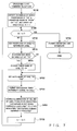
- the CPU 18 determines whether a crossfade is being currently carried out. If so, the crossfade start command is ignored. If, on the other hand, no crossfade is being currently carried out, then a crossfade start command reception routine of Fig. 7 is started up.
- the setting information table 30 is referenced to detect all of the input channels of which the FADER mode is "ON” and the CROSSFADE mode is "FROM” or "TO", and the number of the thus-detected input channels is assigned to a variable n. Also, the individual detected input channels are assigned to an array CH; namely, the constituent elements of the array CH are channels CH[1] - CH[n]. Further, a count variable k for counting the input channels is set at "1".
- step SP44 of Fig. 7 a determination is made as to whether the count variable k has exceeded the number n of the channels. With a NO determination at step SP44, the routine goes to step SP46.
- step SP46 the reference level of the channel CH[k] is read out from the reference level designation section 38, and the current area 16a is updated so that the fader gain of the channel CH[k] equals the reference level.
- step SP48 a determination is made as to whether the CROSSFADE mode of the channel CH[k] is currently set at "TO”. If a YES determination is made at step S48, the routine moves on to step SP50, where the current area 16a is updated so that the fader gain of the channel CH[k] takes a lowest level "- ⁇ ".
- the fader gain is set at the reference level when the CROSSFADE mode is "FROM”, but set at the lowest level “- ⁇ " when the CROSSFADE mode is "TO".
- the corresponding electric fader 524 is driven to automatically move to a position corresponding to the fader gain.
- the AUTO mode of the channel CH[k] is set at "ON”.
- a crossfade timer interrupt corresponding to the channel CH[k] is permitted.
- the "crossfade timer interrupt” is an interrupt which is generated every predetermined time (i.e., every crossfade timer interrupt period) during execution of the crossfade and per input channel for which the interrupt is permitted and which is intended to gradually vary the fader gain of the input channel. Whether or not the crossfade timer interrupt should be permitted is set per channel; in this instance, the crossfade timer interrupt is permitted only for the channel CH[k].
- the crossfade start command received from the control apparatus 102, also designates a crossfade execution time (length) from the start to end of the crossfade. Therefore, by dividing the crossfade execution time by the crossfade timer interrupt period, it is possible to obtain the number of interrupts generated within the crossfade execution time.
- the fader gain at the start of the crossfade is at the reference level, while the fader gain at the end of the crossfade is at the lowest level "- ⁇ ".
- the fader gain at the start of the crossfade is at the lowest level "- ⁇ "
- the fader gain at the end of the crossfade is at the reference level.
- step SP56 the LED 516a built in the SEL key 516 of the channel CH[k] is changed from a state indicating "crossfade is not being currently executed” over to a state indicating "crossfade is being currently executed”. Details of the illumination state of the LED are explained with reference to Fig. 10.
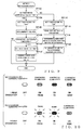
- the SEL key of each channel of which the FADER mode is "OFF' is deilluminated, but the SEL key of each channel of which the FADER mode is "ON” is illuminated continuously in a particular color corresponding to the CROSSFADE mode; for example, if the CROSSFADE mode is "FROM”, the SEL key is continuously illuminated in red, if the CROSSFADE mode is "TO”, the SEL key is continuously illuminated in orange, or if the CROSSFADE mode is "NONE", the SEL key is continuously illuminated in green.
- the SEL key of each channel of which the FADER mode is "OFF' and the SEL key for each channel which the FADER mode is "ON” and the CROSSFADE mode is "NONE" are placed in the same illumination state as when “crossfade is not being currently executed".
- the SEL key 516 is set in a blinking state. More specifically, if the CROSSFADE mode is "FROM”, the SEL key is blinked in red, if the CROSSFADE mode is "TO”, the SEL key is blinked in orange. In this way, each fader that is being actually driven can be informed to the human operator or user by the blinking of the built-in LED of the SEL key 516.
- step SP44 the count variable k is incremented by one at step SP58 and then the routine reverts to step SP44, so that the operations at and after step S44 are repeated for all of the channels CH[1] - CH[n].
- a YES determination is made at step SP44 so that the routine goes to step SP59, where a crossfade end interrupt is permitted.
- the "crossfade end interrupt" is an interrupt which is generated every predetermined time (i.e., every crossfade end interrupt period) during execution of the crossfade and which is intended to determine whether the crossfade execution time has passed.
- a crossfade timer interrupt routine of Fig. 8A is started up.
- a determination is made as to whether or not the AUTO mode of the input channel to be subjected to the current interrupt process is currently "ON". With a NO determination at step SP62, the instant routine is brought to an end without any substantial operation being carried out.
- step SP62 If, on the other hand, a YES determination is made at step SP62, the routine moves on to step SP64, where the fader gain (i.e., fader gain value stored in the current area 16a and position of the fader corresponding to the channel) is varied by the variation amount calculated earlier for the input channel at step SP54.
- the fader gain i.e., fader gain value stored in the current area 16a and position of the fader corresponding to the channel
- the routine moves on to step SP64, where the fader gain (i.e., fader gain value stored in the current area 16a and position of the fader corresponding to the channel) is varied by the variation amount calculated earlier for the input channel at step SP54.
- the fader gain of each channel of which the AUTO mode is "ON" is updated progressively, by the calculated variation amount at a time, from the fader gain at the start of the crossfade toward the fader gain at the end of the crossfade, in accordance with which the fader is automatically driven in
- a fader operation event process routine of Fig. 8B is started up. This routine is started up in response to manual operation of the fader of any one of the input channels, irrespective of whether crossfade is being currently executed or not.
- a determination is made as to whether crossfade is being currently executed. That "crossfade is being currently executed” means a state after reception of the crossfade start command from the control apparatus 102 but before inhibition of the crossfade end interrupt. If a YES determination is made at step SP72, the routine moves on to step SP74, where it is further determined whether the FADER mode of the input channel corresponding to the operated fader is currently "ON".
- step SP74 the routine proceeds to step SP76, where a further determination is made as to whether the AUTO mode of the input channel is currently "ON". If a YES determination is made at step SP76, the routine moves on to step SP77, where the AUTO mode is set to "OFF". Then, at step SP78, a corresponding portion of the current area 16a is updated in such a manner that the fader gain of the channel equals the actual operating amount (current position) of the fader.
- the human operator has manually operated any of the crossfade-related faders during the execution of crossfade, the operated fader is to be excluded from the crossfade until the current crossfade execution is completed.
- the operation at step SP52 above is again carried out, and thus, the AUTO mode of that input channel is again set to "ON" so that the fader of the input channel will be automatically driven.
- step S77 the routine jumps over step S77 to step SP78. Namely, when no crossfade is being executed and if the FADER mode is "OFF' or the AUTO mode is "OFF', it is only necessary that the corresponding portion of the current area 16a be updated, because the input channel corresponding to the operated fader is not an object of crossfade.
- a crossfade end interrupt routine of Fig. 8C is started up every crossfade end interrupt period.
- a determination is made as to whether the crossfade execution time has passed after the start of the crossfade (i.e., after execution of step SP59). With a NO determination at step SP59, the instant routine is immediately brought to an end.
- step SP82 If, on the other hand, the crossfade execution time has passed as determined at step SP82 (YES determination at step SP82), the routine moves on to step SP84, where the crossfade timer interrupt of Fig. 8A and crossfade end interrupt (Fig. 8C) are inhibited.
- step SP86 the illumination of the SEL key of each of the input channels is changed from the state indicating "crossfade is being currently executed" (section (b) of Fig. 10) over to the state indicating "crossfade is not being currently executed” (section (a) of Fig. 10).
- a SEL Key depression event process routine of Fig. 9 is started up, irrespective of whether crossfade is being currently executed or not.
- step SP102 it is determined whether the FADER mode of the input channel is "ON”. If the FADER mode is "OFF' (NO determination at step SP102), the routine branches to step SP114, where the FADER mode is set to "ON”.
- step SP116 the setting of the CROSSFADE mode of the input channel is read out from the setting information mode 30.
- the illumination state of the SEL key is determined in accordance with the read-out setting of the CROSSFADE mode.
- the illumination state of the SEL key determined here is any one of several examples illustrated in section (a) of Fig. 10.
- step SP102 If, on the other hand, the FADER mode has already been set at "ON" at the time of the depression of the SEL key 516, a YES determination is made at step SP102 and the routine moves on to step SP104, where the FADER mode is set to "OFF'.
- step SP106 the SEL key is deilluminated in accordance with the new FADER mode (i.e., "FADER MODE OFF').
- step SP108 a determination is made whether or not a crossfade is being executed. With a YES determination at step SP108, the routine goes to step SP110, where the AUTO mode of the input channel is set to "OFF'.
- the fader gain of the input channel will not be varied by the crossfade timer interrupt routine.
- the fader gain of the input channel is updated to equal a fader gain before the execution of the crossfade.
- the "fader gain before the execution of the crossfade” is the reference level in the case where the CROSSFADE mode of the channel is "FROM”, but the lowest level “- ⁇ ” in the case where the CROSSFADE mode of the channel is "TO". In this way, the corresponding electric fader is automatically driven to a position corresponding to the new fader gain.
- the first-mentioned approach i.e., item (1) approach
- the second-mentioned approach is useful if used when the input channel in question should be excluded from the current crossfade process but also a subsequent crossfade process.
Landscapes
- Engineering & Computer Science (AREA)
- Multimedia (AREA)
- Circuit For Audible Band Transducer (AREA)
- Amplifiers (AREA)
Applications Claiming Priority (4)
| Application Number | Priority Date | Filing Date | Title |
|---|---|---|---|
| JP2004139254 | 2004-05-07 | ||
| JP2004139253A JP4232685B2 (ja) | 2004-05-07 | 2004-05-07 | ミキサ装置の制御方法、ミキサ装置およびプログラム |
| JP2004139253 | 2004-05-07 | ||
| JP2004139254A JP4232686B2 (ja) | 2004-05-07 | 2004-05-07 | ミキサ装置の制御方法、ミキサ装置およびプログラム |
Publications (2)
| Publication Number | Publication Date |
|---|---|
| EP1596395A2 true EP1596395A2 (de) | 2005-11-16 |
| EP1596395A3 EP1596395A3 (de) | 2007-02-07 |
Family
ID=34939702
Family Applications (1)
| Application Number | Title | Priority Date | Filing Date |
|---|---|---|---|
| EP05103750A Ceased EP1596395A3 (de) | 2004-05-07 | 2005-05-04 | Vorrichtung und Verfahren zur Signalpegelanpassung |
Country Status (2)
| Country | Link |
|---|---|
| US (1) | US7684573B2 (de) |
| EP (1) | EP1596395A3 (de) |
Families Citing this family (10)
| Publication number | Priority date | Publication date | Assignee | Title |
|---|---|---|---|---|
| WO2006022076A1 (ja) * | 2004-08-27 | 2006-03-02 | Matsushita Electric Industrial Co., Ltd. | 情報端末 |
| JP4645347B2 (ja) * | 2005-07-29 | 2011-03-09 | ヤマハ株式会社 | ミキシング装置及びプログラム |
| US8698752B2 (en) * | 2005-11-10 | 2014-04-15 | Id8 Group R2 Studios, Inc. | Multi-functional control interface |
| JP2009521017A (ja) | 2005-11-10 | 2009-05-28 | オープンピーク インコーポレイテッド | 多機能制御インターフェース |
| CN101502089B (zh) | 2006-07-28 | 2013-07-03 | 西门子企业通讯有限责任两合公司 | 进行音频会议的方法、音频会议装置和编码器之间的切换方法 |
| JP5201016B2 (ja) * | 2009-03-10 | 2013-06-05 | ヤマハ株式会社 | オーディオ信号処理装置 |
| EP2424271A4 (de) * | 2009-04-24 | 2012-10-31 | Pioneer Corp | Mischereinrichtung, player, wiedergabesystem, mischereinrichtungssteuerverfahren, player-steuerverfahren und programm |
| JP2011199684A (ja) * | 2010-03-19 | 2011-10-06 | Yamaha Corp | デジタルオーディオミキサ |
| JP5754367B2 (ja) | 2011-12-20 | 2015-07-29 | ヤマハ株式会社 | 音響処理装置および音響システム |
| CA3163435C (en) * | 2020-01-04 | 2024-04-02 | Vaughan RISHER | Fade device |
Citations (5)
| Publication number | Priority date | Publication date | Assignee | Title |
|---|---|---|---|---|
| US5054077A (en) | 1989-07-26 | 1991-10-01 | Yamaha Corporation | Fader device |
| US5177801A (en) | 1990-03-28 | 1993-01-05 | Sony Corporation | Cross fader for editing audio signals |
| US5239458A (en) | 1989-07-26 | 1993-08-24 | Yamaha Corporation | Fader device having a fine adjustment of the signal level |
| US5317641A (en) | 1991-04-11 | 1994-05-31 | Sony Electronics Inc. | Fader depth control apparatus |
| US20020159375A1 (en) * | 2001-04-27 | 2002-10-31 | Pioneer Corporation | Audio signal processor |
Family Cites Families (4)
| Publication number | Priority date | Publication date | Assignee | Title |
|---|---|---|---|---|
| US4947440A (en) * | 1988-10-27 | 1990-08-07 | The Grass Valley Group, Inc. | Shaping of automatic audio crossfade |
| JPH07312022A (ja) | 1994-05-17 | 1995-11-28 | Sony Corp | オーディオミキサ |
| JPH08195068A (ja) * | 1995-01-20 | 1996-07-30 | Pioneer Electron Corp | オーディオ信号混合装置 |
| JP2004112525A (ja) | 2002-09-19 | 2004-04-08 | Yamaha Corp | 音響信号処理装置 |
-
2005
- 2005-05-04 EP EP05103750A patent/EP1596395A3/de not_active Ceased
- 2005-05-06 US US11/123,730 patent/US7684573B2/en not_active Expired - Fee Related
Patent Citations (5)
| Publication number | Priority date | Publication date | Assignee | Title |
|---|---|---|---|---|
| US5054077A (en) | 1989-07-26 | 1991-10-01 | Yamaha Corporation | Fader device |
| US5239458A (en) | 1989-07-26 | 1993-08-24 | Yamaha Corporation | Fader device having a fine adjustment of the signal level |
| US5177801A (en) | 1990-03-28 | 1993-01-05 | Sony Corporation | Cross fader for editing audio signals |
| US5317641A (en) | 1991-04-11 | 1994-05-31 | Sony Electronics Inc. | Fader depth control apparatus |
| US20020159375A1 (en) * | 2001-04-27 | 2002-10-31 | Pioneer Corporation | Audio signal processor |
Non-Patent Citations (1)
| Title |
|---|
| "DM2000 Instruction Manual", February 2002, YAMAHA CORPORATION |
Also Published As
| Publication number | Publication date |
|---|---|
| US7684573B2 (en) | 2010-03-23 |
| US20050249364A1 (en) | 2005-11-10 |
| EP1596395A3 (de) | 2007-02-07 |
Similar Documents
| Publication | Publication Date | Title |
|---|---|---|
| US10425054B2 (en) | Operation panel structure and control method and control apparatus for mixing system | |
| EP1551119A2 (de) | Audio-Mischvorrichtung und Verfahren zur Einstellung von Parameter für die Vorrichtung | |
| US7684573B2 (en) | Signal level adjustment apparatus and control method for the adjustment apparatus | |
| US8744096B2 (en) | Digital audio mixer | |
| EP1530197B1 (de) | Verfahren und Programm zur Steuerung eines Parameters und Vorrichtung zum Einstellen eines Parameters | |
| JP2013110585A (ja) | 音響機器 | |
| US7945060B2 (en) | Parameter display method and program therefor, and parameter setting apparatus | |
| CN100578649C (zh) | 信号电平的调节设备和该调节设备的控制方法 | |
| JP2007074625A (ja) | デジタルミキサおよびプログラム | |
| JP4232686B2 (ja) | ミキサ装置の制御方法、ミキサ装置およびプログラム | |
| EP1571767B1 (de) | Vorrichtung, Verfahren und Programm zur Wiedergabe von Ereignisdaten | |
| JP4259153B2 (ja) | 画像処理装置および画像処理方法を実現するためのプログラム | |
| JP2011172180A (ja) | 音響信号処理装置およびプログラム | |
| JP2005244309A (ja) | イベントデータ再生方法、イベントデータ再生装置、電子機器およびプログラム | |
| JP5464093B2 (ja) | 音響信号処理装置およびプログラム | |
| JP4001121B2 (ja) | イベントデータ再生方法、イベントデータ再生装置、電子機器およびプログラム | |
| JP5061508B2 (ja) | オーディオミキサおよびプログラム | |
| JP5560760B2 (ja) | 音響信号処理装置およびプログラム | |
| JP5510206B2 (ja) | オーディオミキシング装置およびプログラム | |
| JP2007074623A (ja) | デジタルミキサおよびプログラム | |
| JPH03173985A (ja) | マルチトラックレコーダ付ミキサ |
Legal Events
| Date | Code | Title | Description |
|---|---|---|---|
| PUAI | Public reference made under article 153(3) epc to a published international application that has entered the european phase |
Free format text: ORIGINAL CODE: 0009012 |
|
| 17P | Request for examination filed |
Effective date: 20050504 |
|
| AK | Designated contracting states |
Kind code of ref document: A2 Designated state(s): AT BE BG CH CY CZ DE DK EE ES FI FR GB GR HU IE IS IT LI LT LU MC NL PL PT RO SE SI SK TR |
|
| AX | Request for extension of the european patent |
Extension state: AL BA HR LV MK YU |
|
| PUAL | Search report despatched |
Free format text: ORIGINAL CODE: 0009013 |
|
| AK | Designated contracting states |
Kind code of ref document: A3 Designated state(s): AT BE BG CH CY CZ DE DK EE ES FI FR GB GR HU IE IS IT LI LT LU MC NL PL PT RO SE SI SK TR |
|
| AX | Request for extension of the european patent |
Extension state: AL BA HR LV MK YU |
|
| RIC1 | Information provided on ipc code assigned before grant |
Ipc: G11B 27/038 20060101AFI20061229BHEP Ipc: G11B 27/00 20060101ALI20061229BHEP |
|
| RAP1 | Party data changed (applicant data changed or rights of an application transferred) |
Owner name: YAMAHA CORPORATION |
|
| AKX | Designation fees paid |
Designated state(s): AT BE BG CH CY CZ DE DK EE ES FI FR GB GR HU IE IS IT LI LT LU MC NL PL PT RO SE SI SK TR |
|
| 17Q | First examination report despatched |
Effective date: 20110121 |
|
| STAA | Information on the status of an ep patent application or granted ep patent |
Free format text: STATUS: THE APPLICATION HAS BEEN REFUSED |
|
| 18R | Application refused |
Effective date: 20170522 |