EP1596049A1 - Verbindungsvorrichtung - Google Patents
Verbindungsvorrichtung Download PDFInfo
- Publication number
- EP1596049A1 EP1596049A1 EP05004529A EP05004529A EP1596049A1 EP 1596049 A1 EP1596049 A1 EP 1596049A1 EP 05004529 A EP05004529 A EP 05004529A EP 05004529 A EP05004529 A EP 05004529A EP 1596049 A1 EP1596049 A1 EP 1596049A1
- Authority
- EP
- European Patent Office
- Prior art keywords
- receiving tube
- pipe
- connecting device
- gas inlet
- exhaust gas
- Prior art date
- Legal status (The legal status is an assumption and is not a legal conclusion. Google has not performed a legal analysis and makes no representation as to the accuracy of the status listed.)
- Granted
Links
Images

Classifications
-
- F—MECHANICAL ENGINEERING; LIGHTING; HEATING; WEAPONS; BLASTING
- F01—MACHINES OR ENGINES IN GENERAL; ENGINE PLANTS IN GENERAL; STEAM ENGINES
- F01N—GAS-FLOW SILENCERS OR EXHAUST APPARATUS FOR MACHINES OR ENGINES IN GENERAL; GAS-FLOW SILENCERS OR EXHAUST APPARATUS FOR INTERNAL-COMBUSTION ENGINES
- F01N13/00—Exhaust or silencing apparatus characterised by constructional features
- F01N13/18—Construction facilitating manufacture, assembly, or disassembly
- F01N13/1838—Construction facilitating manufacture, assembly, or disassembly characterised by the type of connection between parts of exhaust or silencing apparatus, e.g. between housing and tubes, between tubes and baffles
- F01N13/1844—Mechanical joints
-
- F—MECHANICAL ENGINEERING; LIGHTING; HEATING; WEAPONS; BLASTING
- F01—MACHINES OR ENGINES IN GENERAL; ENGINE PLANTS IN GENERAL; STEAM ENGINES
- F01N—GAS-FLOW SILENCERS OR EXHAUST APPARATUS FOR MACHINES OR ENGINES IN GENERAL; GAS-FLOW SILENCERS OR EXHAUST APPARATUS FOR INTERNAL-COMBUSTION ENGINES
- F01N13/00—Exhaust or silencing apparatus characterised by constructional features
- F01N13/18—Construction facilitating manufacture, assembly, or disassembly
- F01N13/1805—Fixing exhaust manifolds, exhaust pipes or pipe sections to each other, to engine or to vehicle body
- F01N13/1827—Sealings specially adapted for exhaust systems
Definitions
- the invention relates to a connecting device according to the preamble of Patent claim 1.
- a connecting device for exhaust pipes is known, the End-shaped and formed in cross-section V-shaped connecting elements exhibit.
- WO 02/066801 A1 discloses a connecting device for Exhaust pipes are known in which the one exhaust pipe an outwardly directed Connecting flange and the other subsequent exhaust pipe with a cross section is provided approximately V-shaped connecting element.
- the object of the invention is to provide an improved connection device for exhaust pipes create, so that a replacement of a catalyst from one of the exhaust pipes is simplified and beyond a decrease in gas temperature before the Catalyst is avoided.
- the advantages achieved by the invention are that on the one hand a quick and easy replaceability of a catalyst from the receiving tube is ensured by means of the connecting device and on the other is the Gas flow guide before the catalyst should not be restricted.
- This will be in Substantially achieved by having a front flange of the Exhaust inlet pipe is connected in a cross-sectionally V-shaped ring element, with one of its inclined surfaces on an opposite inclined surface of an im Cross-section angular ring member is supported.
- This ring element is with the Receiving tube connected, wherein the V-shaped ring member and the angular Ring element together by a V-shaped clamp of a connecting device cohesively overlapping.
- This configuration and arrangement of the connecting device is the Flow path in the exhaust gas inlet tube unhindered by the device and the Connecting device can be closed in a simple manner and to remove the Catalyst are opened.
- the end flange of the Exhaust inlet pipe extends radially outward and in a plane with a opposite connecting flange of the V-shaped ring element is arranged, which engages the receiving tube from the outside.
- the angular ring element with a Leg arranged in the region of the insulation of the catalyst and with the Pick-up tube connected in this area, with the subsequent subsequent Leg, the oblique surface of the V-shaped ring member engages from the outside and is arranged corresponding thereto.
- the Exhaust gas inlet tube and the receiving tube each with a cross section angular ring member is connected, both in a radial plane have projecting mounting flange, which opposite one another and each other are connectable. Also in this embodiment is connected to the receiving tube angular ring element with its one leg in the field of insulation of the Catalyst and is connected to the receiving tube.
- This version becomes a simple fast to be solved and closed connecting device of exhaust pipes which also includes all the advantages of the aforementioned embodiment, such as in particular the flow guidance and the gas temperature before the catalyst.
- the angular ring element is the end of the Gas inlet tube formed and the V-shaped further ring element is with a Leg attached to the pick-up tube in the insulation area.
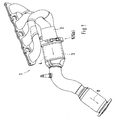
- An exhaust system 1 includes i.a. an exhaust gas inlet pipe 2, which with a Receiving tube 3 for a catalyst 4 via a connecting device 5; 5a; 5b connected is.
- the catalyst 4 is surrounded by an insulation 6 and in the receiving tube 3, wherein an exhaust stream 8 coming from the engine in the direction of arrow the Exhaust gas inlet pipe 2 and subsequently flows through the catalyst 4 and the insulation. 6 to prevent heat dissipation.
- the connecting device 5; 5a; 5b provided.
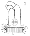
- This consists in a first embodiment. of Fig. 1 and 2 and 4, respectively an end flange 9 on an end face of the exhaust gas inlet pipe 2, which is in a plane X-X extends radially outward.
- this flange 9 is a cross-section V-shaped ring member 10 is connected, which for this purpose a the front flange. 9 has opposing mounting surface 11 and the flange 9 and this Attachment surface 11 via a weld or soldering 12 connected together are.
- the V-shaped ring element 10 comprises two roof-shaped inclined surfaces 14, 15, wherein the one inclined surface 15 of the ring member 10 a further angular Ring element 16 is trimmed, fixed with the receiving tube 3 for the catalyst 4 connected via a weld or soldering 17.
- the angular ring element 16a is mitangeformt end of the gas inlet tube 2 and the V-shaped ring member 10a is attached to the receiving tube 3 for the catalyst 4, as shown in Fig. 4 in more detail.
- the ring member 16 acc. Fig. 2 is angled in cross-section with legs executed, the inclined surfaces 18, 19 form, wherein the one inclined surface 18 with the Pick-up tube 3 and the other, at an obtuse angle employed inclined surface corresponding to the inclined surface 15 of the ring member 10 for connection is arranged.
- the end flange 9 of the exhaust gas inlet pipe 2 is provided with an opening cross-section provided to the catalyst 4, which is approximately the diameter of the catalyst. 4 equivalent.
- the insulation 6 in the receiving tube 3 for the catalyst 4 extends almost to the end face of the catalyst 4 and in the region of the insulation 6 is the arranged angular element 16 and connected to the receiving tube 3.
Landscapes
- Engineering & Computer Science (AREA)
- Chemical & Material Sciences (AREA)
- Combustion & Propulsion (AREA)
- Mechanical Engineering (AREA)
- General Engineering & Computer Science (AREA)
- Exhaust Gas After Treatment (AREA)
Abstract
Description
- Fig. 1
- einen Schnitt durch eine Verbindungsvorrichtung zwischen einem Gaseintrittsrohr und einem Aufnahmerohr für einen Katalysator,
- Fig. 2
- eine schaubildliche Darstellung eines Teiles der Abgasanlage mit der Verbindungsvorrichtung,
- Fig. 3
- eine weitere Ausführung einer Verbindungsvorrichtung zwischen dem Abgaseintrittsrohr und dem Aufnahmerohr für einen Katalysator und
- Fig. 4
- eine weitere Ausführung einer Verbindungsvorrichtung zwischen dem Abgaseintrittsrohr und dem Aufnahmerohr für einen Katalysator.
Claims (7)
- Verbindungsvorrichtung für Rohre einer Abgasanlage, wobei das eine Rohr als Abgaseintrittsrohr und das weitere anschließende Rohr als Aufnahmerohr für einen mit einer Isolierung versehenen Katalysator ausgeführt ist und das Abgaseintrittsrohr mit dem Aufnahmerohr über eine Klemmverbindung lösbar miteinander verbunden sind, dadurch gekennzeichnet, dass mit einem stirnseitigen Flansch (9) des Abgaseintrittsrohres (2) ein im Querschnitt V-förmiges Ringelement (10) verbunden ist, das mit einer seiner Schrägflächen (15) an einer gegenüberstehenden Schrägfläche (19) eines im Querschnitt winkelförmigen Ringelements (16) abgestützt ist und welches mit dem Aufnahmerohr (3) verbunden ist und das V-förmige Ringelement (10) und das winkelförmige Ringelement (16) gemeinsam von einer V-förmigen Spannschelle (S) einer Verbindungsvorrichtung (5) zusammenhaltend übergriffen sind.
- Verbindungsvorrichtung nach Anspruch 1, dadurch gekennzeichnet, dass der stirnseitige Flansch (9) des Abgaseintrittsrohres (2) sich radial nach außen erstreckt und in einer Ebene (X-X) mit einem gegenüberstehenden Verbindungsflansch (11) des V-förmigen Ringelements (10) angeordnet ist, welches das Aufnahmerohr (3) von außen übergreift.
- Verbindungsvorrichtung nach den Ansprüchen 1 oder 2, dadurch gekennzeichnet, dass das winkelförmige Ringelement (10) mit einem Schenkel (18) im Bereich der Isolierung (6) des Katalysators (4) angeordnet und mit dem Aufnahmerohr (3) verbunden ist, wobei der weitere anschließende Schenkel mit der Schrägfläche (19) die Schrägfläche (15) des V-förmigen Ringelements (10) von außen übergreift und korrespondierend mit dieser angeordnet ist.
- Verbindungsvorrichtung nach den Ansprüchen 1, 2 oder 3, dadurch gekennzeichnet, dass die Spannschelle (S) das V-förmige Ringelement (10) und das weitere winkelförmige Ringelement (16) unter einer Klemmwirkung von außen übergreift.
- Verbindungsvorrichtung für Rohre einer Abgasanlage, wobei das eine Rohr als Abgaseintrittsrohr und das weitere anschließende Rohr als Aufnahmerohr für einen von einer Isolierung umgebenden Katalysator ausgeführt ist und das Abgaseintrittsrohr mit dem Aufnahmerohr über eine Klemmverbindung miteinander lösbar verbunden sind, dadurch gekennzeichnet, dass das winkelförmige Ringelement (16a) endseitig des Abgaseintrittsrohres (2) angeformt ist und das weitere V-förmige Ringelement (10a) mit einem Schenkel (10b) am Aufnahmerohr (3) im Bereich der Isolierung (6) für den Katalysator (4) befestigt und die Ringelemente (10a und 16a) über eine Verbindungsvorrichtung (5b) miteinander verbindbar sind.
- Verbindungsvorrichtung für Rohre einer Abgasanlage, wobei das eine Rohr als Abgaseintrittsrohr und das weitere anschließende Rohr als Aufnahmerohr für einen von einer Isolierung umgebenden Katalysators ausgeführt ist und das Abgaseintrittsrohr mit dem Aufnahmerohr über eine Klemmverbindung miteinander lösbar verbunden sind, dadurch gekennzeichnet, dass das Abgaseintrittsrohr (2) sowie das Aufnahmerohr (3) jeweils mit einem im Querschnitt winkelförmigen Ringelement (22, 23) verbunden ist, die jeweils einen in einer Ebene (X-X) radial vorragenden Befestigungsflansch (26, 27) aufweisen, welche gegenüberstehend und über eine Verbindungsvorrichtung (5a) miteinander verbindbar sind.
- Verbindungsvorrichtung nach Anspruch 6, dadurch gekennzeichnet, dass das mit dem Aufnahmerohr (3) verbundene winkelförmige Ringelement (22) mit seinem einem Schenkel (24) im Bereich der Isolierung (6) des Katalysators (4) liegt und mit dem Aufnahmerohr (3) verbunden ist.
Applications Claiming Priority (2)
| Application Number | Priority Date | Filing Date | Title |
|---|---|---|---|
| DE102004023995A DE102004023995A1 (de) | 2004-05-14 | 2004-05-14 | Verbindungsvorrichtung |
| DE102004023995 | 2004-05-14 |
Publications (2)
| Publication Number | Publication Date |
|---|---|
| EP1596049A1 true EP1596049A1 (de) | 2005-11-16 |
| EP1596049B1 EP1596049B1 (de) | 2009-09-09 |
Family
ID=34934014
Family Applications (1)
| Application Number | Title | Priority Date | Filing Date |
|---|---|---|---|
| EP05004529A Expired - Lifetime EP1596049B1 (de) | 2004-05-14 | 2005-03-02 | Verbindungsvorrichtung |
Country Status (3)
| Country | Link |
|---|---|
| US (1) | US20050253387A1 (de) |
| EP (1) | EP1596049B1 (de) |
| DE (2) | DE102004023995A1 (de) |
Cited By (3)
| Publication number | Priority date | Publication date | Assignee | Title |
|---|---|---|---|---|
| EP1788214A1 (de) * | 2005-11-21 | 2007-05-23 | Delphi Technologies, Inc. | Abgasbehandlungseinrichtung mit einer Falzung und Montageverfahren dafür |
| EP2239434A1 (de) * | 2009-04-02 | 2010-10-13 | J. Eberspächer GmbH & Co. KG | Abgasbehandlungseinrichtung und zugehöriges Herstellungsverfahren |
| DE102009057623A1 (de) * | 2009-12-09 | 2011-06-16 | Volkswagen Ag | Anordnung einer Abgasbehandlungseinrichtung an einem Abgasturbolader |
Families Citing this family (5)
| Publication number | Priority date | Publication date | Assignee | Title |
|---|---|---|---|---|
| US8327539B2 (en) | 2006-01-11 | 2012-12-11 | Cummins Filtration Ip, Inc | System and method for facilitating proper assembly of an exhaust system |
| DE102009024534A1 (de) * | 2009-06-10 | 2010-12-16 | J. Eberspächer GmbH & Co. KG | Abgasreinigungseinrichtung |
| DE102010045871A1 (de) * | 2010-09-17 | 2012-03-22 | Emitec Gesellschaft Für Emissionstechnologie Mbh | Abgasbehandlungseinheit für eine AGR-Leitung |
| JP6651564B2 (ja) * | 2018-03-15 | 2020-02-19 | 本田技研工業株式会社 | フランジの締結構造 |
| US12546244B1 (en) * | 2024-12-09 | 2026-02-10 | Cummins Emission Solutions Inc. | Exhaust treatment devices for exhaust aftertreatment system |
Citations (6)
| Publication number | Priority date | Publication date | Assignee | Title |
|---|---|---|---|---|
| US5257834A (en) * | 1990-09-07 | 1993-11-02 | Rasmussen Gmbh | Pipe coupling |
| DE29503550U1 (de) * | 1995-03-02 | 1995-05-11 | Zeuna-Stärker GmbH & Co KG, 86154 Augsburg | Abgasanlage |
| US5454604A (en) * | 1992-05-18 | 1995-10-03 | Toyoda Jidosha Kabushiki Kaisha | Vortex gasket for automotive exhaust system |
| DE19959955A1 (de) | 1998-12-14 | 2000-06-21 | Ecia Equip Composants Ind Auto | Vorrichtung zur Reinigung der Abgase eines Verbrennungsmotors |
| FR2810716A1 (fr) * | 2000-06-23 | 2001-12-28 | Peugeot Citroen Automobiles Sa | Dispositif d'accouplement de deux elements tubulaires formant notamment des elements d'une ligne d'echappement de vehicule automobile |
| FR2821117A1 (fr) * | 2001-02-21 | 2002-08-23 | Faurecia Ind | Dispositif nettoyable de depollution des gaz d'echappement d'un moteur |
Family Cites Families (6)
| Publication number | Priority date | Publication date | Assignee | Title |
|---|---|---|---|---|
| CH555022A (de) * | 1972-08-10 | 1974-10-15 | Oetiker Hans | Rohrverbindung. |
| EP1026376A3 (de) * | 1999-02-05 | 2003-07-23 | Witzenmann GmbH | Abkoppelelement zur Abkopplung von Schwingungen |
| JP2001166162A (ja) * | 1999-12-09 | 2001-06-22 | Hitachi Cable Ltd | アレイ導波路型グレーティング |
| AT4835U1 (de) * | 2000-11-13 | 2001-12-27 | Tesma Motoren Getriebetechnik | Treibstoffbehälter mit einem rohr |
| FR2817012B1 (fr) * | 2000-11-21 | 2004-07-09 | Peugeot Citroen Automobiles Sa | Systeme de fixation de deux organes de depollution dans une ligne d'echappement de moteur de vehicule automobile |
| US7047731B2 (en) * | 2002-02-27 | 2006-05-23 | Delphi Technologies, Inc. | Diesel particulate filter ash removal |
-
2004
- 2004-05-14 DE DE102004023995A patent/DE102004023995A1/de not_active Ceased
-
2005
- 2005-03-02 EP EP05004529A patent/EP1596049B1/de not_active Expired - Lifetime
- 2005-03-02 DE DE502005008087T patent/DE502005008087D1/de not_active Expired - Lifetime
- 2005-05-13 US US11/128,186 patent/US20050253387A1/en not_active Abandoned
Patent Citations (7)
| Publication number | Priority date | Publication date | Assignee | Title |
|---|---|---|---|---|
| US5257834A (en) * | 1990-09-07 | 1993-11-02 | Rasmussen Gmbh | Pipe coupling |
| US5454604A (en) * | 1992-05-18 | 1995-10-03 | Toyoda Jidosha Kabushiki Kaisha | Vortex gasket for automotive exhaust system |
| DE29503550U1 (de) * | 1995-03-02 | 1995-05-11 | Zeuna-Stärker GmbH & Co KG, 86154 Augsburg | Abgasanlage |
| DE19959955A1 (de) | 1998-12-14 | 2000-06-21 | Ecia Equip Composants Ind Auto | Vorrichtung zur Reinigung der Abgase eines Verbrennungsmotors |
| FR2810716A1 (fr) * | 2000-06-23 | 2001-12-28 | Peugeot Citroen Automobiles Sa | Dispositif d'accouplement de deux elements tubulaires formant notamment des elements d'une ligne d'echappement de vehicule automobile |
| FR2821117A1 (fr) * | 2001-02-21 | 2002-08-23 | Faurecia Ind | Dispositif nettoyable de depollution des gaz d'echappement d'un moteur |
| WO2002066801A1 (fr) | 2001-02-21 | 2002-08-29 | Faurecia Systemes D'echappement | Dispositif nettoyable de depollution des gaz d'echappement d'un moteur |
Cited By (4)
| Publication number | Priority date | Publication date | Assignee | Title |
|---|---|---|---|---|
| EP1788214A1 (de) * | 2005-11-21 | 2007-05-23 | Delphi Technologies, Inc. | Abgasbehandlungseinrichtung mit einer Falzung und Montageverfahren dafür |
| EP2239434A1 (de) * | 2009-04-02 | 2010-10-13 | J. Eberspächer GmbH & Co. KG | Abgasbehandlungseinrichtung und zugehöriges Herstellungsverfahren |
| DE102009057623A1 (de) * | 2009-12-09 | 2011-06-16 | Volkswagen Ag | Anordnung einer Abgasbehandlungseinrichtung an einem Abgasturbolader |
| DE102009057623B4 (de) | 2009-12-09 | 2024-12-12 | Volkswagen Ag | Anordnung einer Abgasbehandlungseinrichtung an einem Abgasturbolader sowie Brennkraftmaschine mit solcher Anordnung |
Also Published As
| Publication number | Publication date |
|---|---|
| DE502005008087D1 (de) | 2009-10-22 |
| EP1596049B1 (de) | 2009-09-09 |
| US20050253387A1 (en) | 2005-11-17 |
| DE102004023995A1 (de) | 2005-12-08 |
Similar Documents
| Publication | Publication Date | Title |
|---|---|---|
| EP2420656B1 (de) | Abgasreinigungsvorrichtung, Abgasanlage, Ausbauverfahren | |
| DE3817413A1 (de) | Verbindungsanordnung fuer abzweigrohre in einem hochdruckkraftstoff-rohrverteiler | |
| DE102004050300A1 (de) | Profilschelle | |
| EP0093328B1 (de) | Anschluss-Formstück | |
| DE19712608A1 (de) | Abgasbehandlungsvorrichtung für Kraftfahrzeuge | |
| EP1596049B1 (de) | Verbindungsvorrichtung | |
| EP2915973B1 (de) | Trichter-Rohr-Anordnung | |
| DE1935602A1 (de) | Schalldaempfer fuer Verbrennungsmotoren | |
| DE3916872C1 (de) | ||
| DE19964223A1 (de) | Spannvorrichtung für eine schwingungsentkoppelnde Flanschverbindung | |
| DE19728815C2 (de) | Rohrverbindung zweier sich überlappender Rohre | |
| EP1603776B1 (de) | Insassenschutzeinrichtung | |
| DE3804559C2 (de) | ||
| DE10044336A1 (de) | Flanschverbindung für Hochdruck-Doppelmantelrohre | |
| EP0654599B1 (de) | Einrichtung zur Abgasrückführung | |
| EP1445526A1 (de) | Fixierteil für eine Schlauchschelle | |
| DE3914992C2 (de) | Vorrichtung zum Verbinden der Enden von mit einer Drahtumflechtung versehenen Ringwellenschläuchen | |
| DE10105390C1 (de) | Plattenschieber | |
| EP0256394B1 (de) | Verfahren zum Herstellen einer für flüssige oder gasförmige Medien bestimmten Leitung | |
| DE102008017894B4 (de) | Zweiflutiger Schalldämpferaustritt | |
| EP3401584A1 (de) | Rohr, insbesondere abgasführungsrohr | |
| DE10354696B4 (de) | Heftvorrichtung | |
| DE102005031944B4 (de) | Modularer Schalldämpfer für die Abgasanlage eines Kraftfahrzeugs | |
| DE10228485A1 (de) | Rohranordnung | |
| DE10303691A1 (de) | Verfahren und Vorrichtung zum Laserschweissen von Schläuchen in einem Lufteinlasssystem |
Legal Events
| Date | Code | Title | Description |
|---|---|---|---|
| PUAI | Public reference made under article 153(3) epc to a published international application that has entered the european phase |
Free format text: ORIGINAL CODE: 0009012 |
|
| AK | Designated contracting states |
Kind code of ref document: A1 Designated state(s): AT BE BG CH CY CZ DE DK EE ES FI FR GB GR HU IE IS IT LI LT LU MC NL PL PT RO SE SI SK TR |
|
| AX | Request for extension of the european patent |
Extension state: AL BA HR LV MK YU |
|
| 17P | Request for examination filed |
Effective date: 20060516 |
|
| AKX | Designation fees paid |
Designated state(s): DE ES FR GB IT |
|
| 17Q | First examination report despatched |
Effective date: 20071008 |
|
| RAP1 | Party data changed (applicant data changed or rights of an application transferred) |
Owner name: DR. ING. H.C. F. PORSCHE AKTIENGESELLSCHAFT |
|
| RAP1 | Party data changed (applicant data changed or rights of an application transferred) |
Owner name: DR. ING. H.C. F. PORSCHE AKTIENGESELLSCHAFT |
|
| GRAC | Information related to communication of intention to grant a patent modified |
Free format text: ORIGINAL CODE: EPIDOSCIGR1 |
|
| GRAP | Despatch of communication of intention to grant a patent |
Free format text: ORIGINAL CODE: EPIDOSNIGR1 |
|
| GRAS | Grant fee paid |
Free format text: ORIGINAL CODE: EPIDOSNIGR3 |
|
| GRAA | (expected) grant |
Free format text: ORIGINAL CODE: 0009210 |
|
| AK | Designated contracting states |
Kind code of ref document: B1 Designated state(s): DE ES FR GB IT |
|
| REG | Reference to a national code |
Ref country code: GB Ref legal event code: FG4D Free format text: NOT ENGLISH |
|
| REF | Corresponds to: |
Ref document number: 502005008087 Country of ref document: DE Date of ref document: 20091022 Kind code of ref document: P |
|
| PG25 | Lapsed in a contracting state [announced via postgrant information from national office to epo] |
Ref country code: ES Free format text: LAPSE BECAUSE OF FAILURE TO SUBMIT A TRANSLATION OF THE DESCRIPTION OR TO PAY THE FEE WITHIN THE PRESCRIBED TIME-LIMIT Effective date: 20091220 |
|
| PLBE | No opposition filed within time limit |
Free format text: ORIGINAL CODE: 0009261 |
|
| STAA | Information on the status of an ep patent application or granted ep patent |
Free format text: STATUS: NO OPPOSITION FILED WITHIN TIME LIMIT |
|
| 26N | No opposition filed |
Effective date: 20100610 |
|
| GBPC | Gb: european patent ceased through non-payment of renewal fee |
Effective date: 20100302 |
|
| REG | Reference to a national code |
Ref country code: FR Ref legal event code: TP |
|
| PG25 | Lapsed in a contracting state [announced via postgrant information from national office to epo] |
Ref country code: GB Free format text: LAPSE BECAUSE OF NON-PAYMENT OF DUE FEES Effective date: 20100302 |
|
| PGFP | Annual fee paid to national office [announced via postgrant information from national office to epo] |
Ref country code: FR Payment date: 20110404 Year of fee payment: 7 Ref country code: IT Payment date: 20110324 Year of fee payment: 7 |
|
| REG | Reference to a national code |
Ref country code: FR Ref legal event code: ST Effective date: 20121130 |
|
| PG25 | Lapsed in a contracting state [announced via postgrant information from national office to epo] |
Ref country code: FR Free format text: LAPSE BECAUSE OF NON-PAYMENT OF DUE FEES Effective date: 20120402 |
|
| PG25 | Lapsed in a contracting state [announced via postgrant information from national office to epo] |
Ref country code: IT Free format text: LAPSE BECAUSE OF NON-PAYMENT OF DUE FEES Effective date: 20120302 |
|
| PGFP | Annual fee paid to national office [announced via postgrant information from national office to epo] |
Ref country code: DE Payment date: 20140304 Year of fee payment: 10 |
|
| REG | Reference to a national code |
Ref country code: DE Ref legal event code: R119 Ref document number: 502005008087 Country of ref document: DE |
|
| PG25 | Lapsed in a contracting state [announced via postgrant information from national office to epo] |
Ref country code: DE Free format text: LAPSE BECAUSE OF NON-PAYMENT OF DUE FEES Effective date: 20151001 |