EP1595746A1 - Flächengebilde für eine Laderaumabdeckung eines Kraftfahrzeuges - Google Patents
Flächengebilde für eine Laderaumabdeckung eines Kraftfahrzeuges Download PDFInfo
- Publication number
- EP1595746A1 EP1595746A1 EP05010117A EP05010117A EP1595746A1 EP 1595746 A1 EP1595746 A1 EP 1595746A1 EP 05010117 A EP05010117 A EP 05010117A EP 05010117 A EP05010117 A EP 05010117A EP 1595746 A1 EP1595746 A1 EP 1595746A1
- Authority
- EP
- European Patent Office
- Prior art keywords
- frame
- cover
- cover element
- sheet material
- material according
- Prior art date
- Legal status (The legal status is an assumption and is not a legal conclusion. Google has not performed a legal analysis and makes no representation as to the accuracy of the status listed.)
- Granted
Links
Images
Classifications
-
- B—PERFORMING OPERATIONS; TRANSPORTING
- B60—VEHICLES IN GENERAL
- B60R—VEHICLES, VEHICLE FITTINGS, OR VEHICLE PARTS, NOT OTHERWISE PROVIDED FOR
- B60R5/00—Compartments within vehicle body primarily intended or sufficiently spacious for trunks, suit-cases, or the like
- B60R5/04—Compartments within vehicle body primarily intended or sufficiently spacious for trunks, suit-cases, or the like arranged at rear of vehicle
- B60R5/044—Compartments within vehicle body primarily intended or sufficiently spacious for trunks, suit-cases, or the like arranged at rear of vehicle luggage covering means, e.g. parcel shelves
- B60R5/045—Compartments within vehicle body primarily intended or sufficiently spacious for trunks, suit-cases, or the like arranged at rear of vehicle luggage covering means, e.g. parcel shelves collapsible or transformable
- B60R5/047—Compartments within vehicle body primarily intended or sufficiently spacious for trunks, suit-cases, or the like arranged at rear of vehicle luggage covering means, e.g. parcel shelves collapsible or transformable collapsible by rolling-up
Definitions
- the invention relates to a fabric for a load compartment cover a motor vehicle with a passage opening through a cover is at least partially closable, which between a at least the passage opening releasing deflection position and a closing position covering the passage opening is movable.
- the pull-out luggage compartment cover has its Auszieh technologyen forehead area a sheet in the form of a Kontmatis on, in which a passage opening is provided.
- the passage opening is with a pivoting cover provided to the insight through the passage opening into the below the load compartment cover allow loading space. This cover is by spring force against a bottom of an edge of the passage opening held. The edge of the passage opening forms a stop for the cover element.
- the passage opening is at the appropriate Intervention by finger of a hand of an operator from above inevitably pushed down, causing the controversy in the field the passage opening can be taken.
- an independent closing of the passage opening through the cover is pivotally articulated by a bearing axis and is held by a spring element in a closed position. The number of components and the installation is complex.
- From DE 102 18 838 C1 is a sheet with a through-opening known, which by a movable cover at least partially closable.
- the cover member has a smaller one Base on as a free access opening.
- the cover is as freely pivotable through the access opening, to both Side of the access opening designed deflectable cover flap.
- return means required, which by spring elements are formed.
- These spring means are called torsion springs formed on a separately attacking on the cover Axle stub for pivotal mounting of the cover provided are.
- the invention is based on the object, a sheet of the above to create said type, which has a simple design for closing the penetration opening allows.
- At least one Covering element has a flexurally elastic region, the mechanical Parts replaced at least partially.
- the bending elastic area allows easy and comfortable manual intervention and removal the hand from the access opening.
- the cover is due to the engagement with the hand a closed position transferred to a deflection position. After this Transfer the load compartment cover to a rest position or the load compartment Covering position is an independent return of the Covering element in the closed position by the restoring forces, which be constructed during deflection in the bending elastic range.
- the at least one cover member a the passage opening at least partially surrounding frame of thermoplastic or thermosetting material is assigned.
- This frame engages in the Passage opening on the fabric and positioned at least a cover in the passage opening.
- de frame to the opening this is made of thermoplastic or thermosetting material.
- the at least one cover element is according to a first embodiment
- the invention at least partially in the field of free Penetration surface formed elastic bending.
- the cover is thus formed deformable, so that when engaging a hand in the passage opening is deflected only the area through the fingers of one hand will inevitably be displaced. At the same time it is a safe removal of the hand possible without one Risk of injury due to the cover element pushing back into the closed position could exist.
- the at least one bending elastic in the area of the access opening Covering element is according to a preferred embodiment of the invention in the at least partially surrounding the passage opening frame provided by a detachable or non-detachable connection.
- the detachable Connection can for example by a clamping or screw connection respectively.
- a gluing, pressing or Welded connection may be provided.
- the at least one cover element and the passage opening at least partially surrounding frame by a flexurally elastic Area are interconnected.
- This can be a simplification be given the structure.
- a frame part as well as on a frame part arranged cover member is required, which consist of a part to to close the passage opening. A cost-effective design and quick assembly is given by this.
- the flexurally elastic region between the cover member and the frame as a hinge connection, in particular as a film hinge, is formed. This can be easier Make the one-piece between the cover and the frame and be given a stable connection.
- the invention provides that the at least one cover connected to an upper or lower part of a frame is.
- the bending elastic range between the at least one cover element and the passage opening at least partially surrounding frames at the top or bottom be provided.
- the at least one cover element is preferred by at least one Return means held in a closed position.
- the return means Advantageously engages the frame, the flexurally elastic region and / or the cover.
- the return means By the return means, the Taking the closed position after releasing the deflection position supported by removing the hand from the access opening become.
- the frame Return means attached by a detachable or permanent connection is, which acts on an underside of the cover.
- a thickening or reinforcement is provided, causing the Cover is automatically transferred to the closed position.
- a return means may be attached to the cover element, which cooperates with deflection with the frame and a reset effected in the closed position. It is understood that any Combinations thereof may be provided.
- the return means is preferably made of a flexurally elastic or rubber-elastic Material produced, which depends on the size the at least one cover element is selected in hardness.
- the at least one cover element and the at least one frame part are preferred according to the first or further alternative embodiment of the invention designed as an injection molded part. Through this One-piece is an optimization of assembly and production costs given the parts.
- the frame parts by a detachable or non-detachable connection to the fabric are fixed.
- detachable or non-releasable latching or Snap-in connections by injection molding integrated into the frame so that the assembly without additional connecting means allows is.
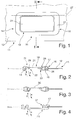
- FIG. 1 shows a sheetlike structure in the form of a load compartment cover 11 partially made of a flexible, in particular textile, material.
- the luggage compartment cover 11 is to cover a loading space provided, extending from a back of a backrest assembly a rear bench seat extends to the tailgate of a vehicle.
- the Load compartment cover 11 is moved from a rest position in which a flexible Fabric is wound on a roller shaft, in a functional position transferred to cover the cargo space, the cargo space cover 11 is hung on brackets.
- a dimensionally stable contour part 12 which has a passage opening 14.
- the access opening 14 is surrounded by a frame 16, which consists of an upper Frame part 17 and a lower frame member 18 ( Figure 2).
- a through the frame 16 limited passage area 19 is through a cover 21, which is arranged in a closed position 22 is.
- FIG. 2 is a sectional view along the line I-I according to FIG. 1 shown.
- the upper and lower frame parts 17, 18 are preferred connected by a plug-in and locking connection 24 and engage in the edge region of the passage opening 14 on the contour part 12th at.
- the cover 21 is connected via a flexurally elastic region 26 with connected to the upper frame part 17 and along a pivot axis 27 (Figure 1) pivotally mounted according to arrow a downwards.
- the bending elastic Region 26 is formed for example as a film hinge.
- This area 26 opposite is on the cover 21 a Stop surface 29 is provided, which preferably over the entire Length of the frame portion 31 extends.
- the abutment surface 29 also along the side frame portions is formed to the pivot axis 27. This is the ingestion given a defined closed position 22.
- the penetration area 19 can be completely closed.
- the stop surface 29 engages the upper frame part 17 at.
- the bending elastic Area 26 associated return means 33 are provided.
- the cover 21 is made a deflection not shown by the return means 33 supported in the closed position 22 according to arrow b transferred and in this held.
- the return means 33 may, for example, to the lower frame member 18 to be molded, so that in one step the return means 33 and the frame part 18 are made.
- the return means 33 can be provided by a detachable or non-detachable connection to the frame part 18, the cover 21 and / or the bending elastic Be arranged area 26.
- the return means 33 extends continuous or in sections along the pivot axis.
- the Return means 33 tapers advantageously in cross section to free deflectable edge of the cover 21st
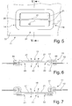
- FIG 3 an alternative embodiment of the invention to the figures 1 and 2 shown.
- the flexurally elastic region 26 is at the bottom Frame part 18 is provided.
- This flexurally elastic region 26 comprises at the same time the return means 33, so that when engaged in the passage area 19 and the transfer of the cover 21 in the deflection position according to arrow a, at the same time restoring forces are built up, the cover 21 automatically in a closed position 22 according to Reset arrow b.
- a surface 36 is in contour to the upper frame part adapted so that in a closed position 22 of the cover 21st a closed surface with the upper frame part 17 is formed is.
- the flexurally elastic region 26 can also be attached to the upper frame part 17 attack.
- FIG. 4 shows a further alternative embodiment of a device according to the invention Sheet formed along the section line I-I shown in Figure 1.
- the cover 21 is itself at least partially designed as flexurally elastic range and goes directly into a portion of the lower frame member 18 via. Consequently may be an area facing the stop surface 26 and / or a transition region be designed elastically bending to the frame part 18. about a stop surface 26 engages the cover 21 on the frame part 18 at.
- the Restoring means 33 which by the formation of the contour in the transition region between the frame part 18 and the cover 21st are integrated, have a bias, so that after the deflection the cover 21 ensures an independent reset is.
- the return means 33 can be integrated as shown be. Also can strip or rib-shaped stiffeners an underside of the cover 21 may be provided.
- the upper Frame 17 advantageously has a circumferential collar 37, which closes the frame 16 to the passage area 19.
- FIG. 5 is a schematic plan view of an alternative invention Design of a fabric given.
- the penetration area 14 is closed by two cover members 21, which According to a first embodiment, the same length legs, whose End faces 41, 42 formed by two parallel edges are.
- the cover 21th are formed differently long.
- the end edges 41, 42 a wave-shaped or zigzagged course.
- these end edges 41, 42 at least partially and / or overlap in sections.
- FIG. 6 is a schematic sectional view taken along the line V-V shown in FIG.
- the cover elements 21 have an edge region 44, which by a detachable or permanent connection with a bottom is provided on the frame part 17.
- the border area 44 also provided on the outside or inside of the lower frame part be.
- the edge regions 41 may alternatively also via the Locking connections 21 to the frame part 17 or 18 to be attached.
- Prefers are the cover 21 in the front near the front Edges 41, 42 formed more flexible than in the area close the frame part 17, 18. In this embodiment, a Jerusalemgriffsdorfkeit both from a top and a bottom given.
- the return means 33 are preferably in the transition region between the frame 16 and a free leg length of the cover 21 integrated or can be separated by the bottom the cover 21 or the frame part 18 arranged elastic Return means 33 may be formed.
- a rubber-elastic Restoring means 33 engage the frame member 18 to at a deflection of the front edge 41 down the cover 21 to transfer into a closed position 22.
- the end edges 41, 42 two to each other have complementary trained stop surfaces to a defined Closed position 22 to take.
- FIG 7 is a schematic sectional view taken along the line V-V shown in Figure 5 a further embodiment of the invention.
- the cover elements 21 may be in a single or multi-component injection molding process be sprayed on the frame 18.
- alternative can be provided that the cover 21 separately to the frame part 17, 18 are produced and by a plug connection to Frame part 17 or 18 are fixed.
- the connector can through Snap or locking elements may be formed or in the form of depressions and Wülsten, which makes it difficult to peel off the cover 21 of the frame member 17 or 18 cause.
- an adhesive or Welded connection may be provided.
- the return means 33 can, for example as wedge-shaped supports on the underside of the cover Attack 21.
- the frame 16 For the production of the frame 16 are preferably injection-moldable materials used, such as PA, PP or the like.
- injection-moldable materials used such as PA, PP or the like.
- flexurally elastic areas are, for example, materials such as TEE, TPE or the like used having a Shore hardness of, for example 50 to 80 shore.
Abstract
Description
- Figur 1
- eine teilweise Draufsicht auf eine Oberseite eines erfindungsgemäßen Flächengebildes in Form einer Laderaumabdeckung für Kraftfahrzeuge,
- Figur 2
- eine schematische Schnittdarstellung entlang der Linie I-I in Figur 1,
- Figur 3
- eine schematische Schnittdarstellung einer alternativen Ausführungsform der Erfindung entlang der Linie I-I in Figur 1,
- Figur 4
- eine schematische Schnittdarstellung einer weiteren alternativen Ausführungsform der Erfindung entlang der Linie I-I in Figur 1,
- Figur 5
- eine schematische Draufsicht auf eine Oberseite eines weiteren erfindungsgemäßen Flächengebildes in Form einer Laderaumabdeckung für Kraftfahrzeuge,
- Figur 6
- eine schematische Schnittdarstellung der Ausführungsform gemäß Figur 5 entlang der Linie V-V und
- Figur 7
- eine schematische Schnittdarstellung einer alternativen Ausführungsform der Erfindung entlang der Linie V-V in Figur 5.
Claims (15)
- Flächengebilde, insbesondere Laderaumabdeckung für eine Kraftfahrzeug, mit einer Durchgriffsöffnung (14), die durch ein Abdeckelement (21) zumindest teilweise verschließbar ist, welches zwischen wenigstens einer die Durchgriffsöffnung (14) freigebenden Auslenkposition und einer die Durchgriffsöffnung (14) abdeckenden Schließposition bewegbar ist, dadurch gekennzeichnet, dass das zumindest eine Abdeckelement (21) einen biegeelastischen Bereich (26) aufweist.
- Flächengebilde nach Anspruch 1 dadurch gekennzeichnet, dass das zumindest eine Abdeckelement (21) einem die Durchgriffsöffnung (14) zumindest teilweise umgebenden Rahmen (16) aus thermoplastischem oder duroplastischem Material zugeordnet ist.
- Flächengebilde nach Anspruch 1 oder 2 dadurch gekennzeichnet, dass das zumindest eine Abdeckelement (21) im Bereich einer freien Durchgriffsfläche (19) zumindest teilweise biegeelastisch ausgebildet ist.
- Flächengebilde nach einem der vorhergehenden Ansprüche, dadurch gekennzeichnet, dass das zumindest eine Abdeckelement (21) einen die Durchgriffsöffnung (14) zumindest teilweise umgebenden Rahmen (16) aufweist und durch eine lösbare oder unlösbare Verbindung an dem Rahmen (16) vorgesehen ist.
- Flächengebilde nach Anspruch 1, dadurch gekennzeichnet, dass das zumindest eine Abdeckelement (21) und ein die Durchgriffsöffnung (14) zumindest teilweise umgebender Rahmen (16) durch einen biegeelastischen Bereich (26) miteinander verbunden sind.
- Flächengebilde nach Anspruch 5, dadurch gekennzeichnet, dass der biegeelastische Bereich (26) als Gelenkverbindung, insbesondere als Filmscharnier, ausgebildet ist.
- Flächengebilde nach einem der vorhergehenden Ansprüche, dadurch gekennzeichnet, dass das zumindest eine Abdeckelement (21) mit einem oberen oder unteren Rahmenteil (17, 18) des Rahmens (16) verbunden ist.
- Flächengebilde nach einem der vorhergehenden Ansprüche, dadurch gekennzeichnet, dass das zumindest eine Abdeckelement (21) mit zumindest einem Rückstellmittel (33) in einer Schließposition (22) gehalten ist, welches zumindest an dem Rahmen (16), dem biegeelastischen Bereich (26) oder dem Abdeckelement (21) vorgesehen ist.
- Flächengebilde nach Anspruch 8, dadurch gekennzeichnet, dass das Rückstellmittel (33) aus einem biegeelastischen Material hergestellt ist, welches zumindest an dem Abdeckelement (21), dem Rahmen (16) oder dem biegeelastischen Bereich (26) angespritzt, durch eine Klebe-, Schweiß-, Klemm- oder Steckverbindung angeordnet ist.
- Flächengebilde nach Anspruch 8 oder 9, dadurch gekennzeichnet, dass die Rückstellmittel (33) eine Härte von 50 bis 80 Schore aufweist.
- Flächengebilde nach einem der vorhergehenden Ansprüche, dadurch gekennzeichnet, dass das zumindest eine Abdeckelement (21) und der zumindest teilweise die Durchgriffsöffnung (14) umgebende Rahmen (16) als ein Spritzgussteil ausgebildet ist.
- Flächengebilde nach einem der vorhergehenden Ansprüche, dadurch gekennzeichnet, dass das zumindest eine Abdeckelement (21) und der zumindest teilweise die Durchgriffsöffnung (14) umgebende Rahmen (16) durch ein Ein- oder Mehrkomponenten-Spritzgussverfahren herstellbar ist.
- Flächengebilde nach einem der vorhergehenden Ansprüche, dadurch gekennzeichnet, dass zumindest eine Oberseite des Abdeckelementes (21) oder des Rahmens (16) eine Beschichtung aufweist, welche der entspricht die an die Durchgriffsöffnung (14) angrenzt.
- Flächengebilde nach Anspruch 13, dadurch gekennzeichnet, dass die Oberfläche des zumindest einen Abdeckelementes (21) oder des Rahmens (16) lackiert ist oder eine dem Flächengebilde entsprechende Folie oder Planware aufweist.
- Flächengebilde nach einem der vorhergehenden Ansprüche, dadurch gekennzeichnet, dass ein mit einem Rahmenteil (17, 18) verbundenes Abdeckelement (21) mit einem weiteren Rahmenteil (18, 17) durch eine lösbare oder unlösbare Verbindung zur Durchtrittsöffnung (14) befestigt ist.
Applications Claiming Priority (2)
| Application Number | Priority Date | Filing Date | Title |
|---|---|---|---|
| DE200420007744 DE202004007744U1 (de) | 2004-05-11 | 2004-05-11 | Flächengebilde für eine Laderaumabdeckung eines Kraftfahrzeugs |
| DE202004007744U | 2004-05-11 |
Publications (2)
| Publication Number | Publication Date |
|---|---|
| EP1595746A1 true EP1595746A1 (de) | 2005-11-16 |
| EP1595746B1 EP1595746B1 (de) | 2007-06-06 |
Family
ID=34936331
Family Applications (1)
| Application Number | Title | Priority Date | Filing Date |
|---|---|---|---|
| EP20050010117 Expired - Fee Related EP1595746B1 (de) | 2004-05-11 | 2005-05-10 | Flächengebilde für eine Laderaumabdeckung eines Kraftfahrzeuges |
Country Status (2)
| Country | Link |
|---|---|
| EP (1) | EP1595746B1 (de) |
| DE (2) | DE202004007744U1 (de) |
Cited By (5)
| Publication number | Priority date | Publication date | Assignee | Title |
|---|---|---|---|---|
| DE102007041147A1 (de) * | 2007-08-30 | 2009-04-23 | Audi Ag | Abdeckung für einen Laderaumboden |
| GB2465463A (en) * | 2008-11-20 | 2010-05-26 | Gm Global Tech Operations Inc | A pivotable handle for the floor of a cargo space |
| US20150020981A1 (en) * | 2013-07-22 | 2015-01-22 | Macauto Industrial Co., Ltd. | Covering curtain |
| FR3011786A1 (fr) * | 2013-10-15 | 2015-04-17 | Cera | Systeme de recouvrement d’un compartiment a bagages de vehicule automobile |
| EP3944989A1 (de) * | 2020-07-29 | 2022-02-02 | Seat, S.A. | Ladebodenplatte für den kofferraum eines fahrzeugs |
Families Citing this family (2)
| Publication number | Priority date | Publication date | Assignee | Title |
|---|---|---|---|---|
| FR2933052B1 (fr) * | 2008-06-27 | 2010-06-04 | Renault Sas | Dispositif cache-bagages comportant une poignee de tirage perfectionnee |
| DE102009055836A1 (de) * | 2009-11-26 | 2011-06-01 | GM Global Technology Operations LLC, ( n. d. Ges. d. Staates Delaware ), Detroit | Verschwenkbare Platte für ein Kraftfahrzeug und Kraftfahrzeug mit einer solchen verschwenkbaren Platte |
Citations (3)
| Publication number | Priority date | Publication date | Assignee | Title |
|---|---|---|---|---|
| DE19707676C1 (de) | 1997-02-26 | 1998-02-26 | Butz Peter Verwaltung | Laderaumabdeckung für Kraftwagen, insbesondere für Kombinations-Personenkraftwagen |
| DE20217717U1 (de) * | 2002-11-08 | 2003-01-16 | Bos Gmbh | Flächengebilde für eine Laderaumabdeckung eines Kraftfahrzeugs |
| DE10218838C1 (de) | 2002-04-23 | 2003-09-25 | Bos Gmbh | Flächengebilde mit einer Durchgriffsöffnung |
-
2004
- 2004-05-11 DE DE200420007744 patent/DE202004007744U1/de not_active Expired - Lifetime
-
2005
- 2005-05-10 DE DE200550000801 patent/DE502005000801D1/de active Active
- 2005-05-10 EP EP20050010117 patent/EP1595746B1/de not_active Expired - Fee Related
Patent Citations (3)
| Publication number | Priority date | Publication date | Assignee | Title |
|---|---|---|---|---|
| DE19707676C1 (de) | 1997-02-26 | 1998-02-26 | Butz Peter Verwaltung | Laderaumabdeckung für Kraftwagen, insbesondere für Kombinations-Personenkraftwagen |
| DE10218838C1 (de) | 2002-04-23 | 2003-09-25 | Bos Gmbh | Flächengebilde mit einer Durchgriffsöffnung |
| DE20217717U1 (de) * | 2002-11-08 | 2003-01-16 | Bos Gmbh | Flächengebilde für eine Laderaumabdeckung eines Kraftfahrzeugs |
Cited By (6)
| Publication number | Priority date | Publication date | Assignee | Title |
|---|---|---|---|---|
| DE102007041147A1 (de) * | 2007-08-30 | 2009-04-23 | Audi Ag | Abdeckung für einen Laderaumboden |
| DE102007041147B4 (de) * | 2007-08-30 | 2016-02-18 | Audi Ag | Abdeckung für einen Laderaumboden |
| GB2465463A (en) * | 2008-11-20 | 2010-05-26 | Gm Global Tech Operations Inc | A pivotable handle for the floor of a cargo space |
| US20150020981A1 (en) * | 2013-07-22 | 2015-01-22 | Macauto Industrial Co., Ltd. | Covering curtain |
| FR3011786A1 (fr) * | 2013-10-15 | 2015-04-17 | Cera | Systeme de recouvrement d’un compartiment a bagages de vehicule automobile |
| EP3944989A1 (de) * | 2020-07-29 | 2022-02-02 | Seat, S.A. | Ladebodenplatte für den kofferraum eines fahrzeugs |
Also Published As
| Publication number | Publication date |
|---|---|
| DE202004007744U1 (de) | 2005-09-29 |
| DE502005000801D1 (de) | 2007-07-19 |
| EP1595746B1 (de) | 2007-06-06 |
Similar Documents
| Publication | Publication Date | Title |
|---|---|---|
| EP1717105B1 (de) | Rollo eben zur Umgebungsfläche | |
| DE19948347B4 (de) | Fahrzeug-Heckkonstruktion | |
| EP1595746A1 (de) | Flächengebilde für eine Laderaumabdeckung eines Kraftfahrzeuges | |
| DE102005056662B4 (de) | Einrichtung zum Befestigen eines Dachgepäckträgers | |
| EP2011723B1 (de) | Luftleiteinrichtung eines Kraftfahrzeuges | |
| DE3009943A1 (de) | Sonnendachaufbau fuer ein fahrzeug | |
| EP2773527A1 (de) | Mittelkonsole | |
| EP0610838B1 (de) | Fussbodenwischer | |
| DE19707676C1 (de) | Laderaumabdeckung für Kraftwagen, insbesondere für Kombinations-Personenkraftwagen | |
| EP1591317B1 (de) | Staufachabdeckung | |
| DE10163150A1 (de) | Gerätetür, vorzugsweise für einen Backofen | |
| EP1612078A1 (de) | Windstopeinrichtung | |
| DE2517077C3 (de) | Halterung für eine Abdeckplatte zwischen der Rücklehne einer hinteren Sitzbank und einer Heckklappe eines Fahrzeugs | |
| DE2132656A1 (de) | Windabweiser fuer das schiebedach eines fahrzeuges | |
| WO2000012373A2 (de) | Seitenplanenaufhängung | |
| DE4106493C1 (en) | Folding roof on vehicle - uses leading and rear transverse slides releasably connectable to roof | |
| DE102005005218A1 (de) | Vorrichtung zum Abdecken eines Spalts zwischen einer Rückenlehne und einem Sitzteil eines Kraftfahrzeugsitzes | |
| WO2017046324A1 (de) | Vorrichtung zur halterung von wenigstens einem behältnis in einem fahrzeuginnenraum | |
| DE10312286B4 (de) | Modularer Windabweiser für ein Schiebedach | |
| EP1530667B1 (de) | Verschlusseinrichtung für fenster, türen od.dgl. öffnungen | |
| WO2018184910A1 (de) | Schiebedach windabweiserelement eines kraftfahrzeugs und windabweiser | |
| DE19524190C1 (de) | Sitzkissen für einen Fahrzeugsitz | |
| DE102005053881B3 (de) | Kraftfahrzeugsitz | |
| DE102004014789B4 (de) | Stoffverdeck für ein Fahrzeug | |
| DE19935651C2 (de) | Fahrzeugdach mit mehreren starren Deckelelementen |
Legal Events
| Date | Code | Title | Description |
|---|---|---|---|
| PUAI | Public reference made under article 153(3) epc to a published international application that has entered the european phase |
Free format text: ORIGINAL CODE: 0009012 |
|
| AK | Designated contracting states |
Kind code of ref document: A1 Designated state(s): AT BE BG CH CY CZ DE DK EE ES FI FR GB GR HU IE IS IT LI LT LU MC NL PL PT RO SE SI SK TR |
|
| AX | Request for extension of the european patent |
Extension state: AL BA HR LV MK YU |
|
| RAP1 | Party data changed (applicant data changed or rights of an application transferred) |
Owner name: REUM GMBH & CO. BETRIEBS KG |
|
| 17P | Request for examination filed |
Effective date: 20060516 |
|
| AKX | Designation fees paid |
Designated state(s): DE FR IT SE |
|
| GRAP | Despatch of communication of intention to grant a patent |
Free format text: ORIGINAL CODE: EPIDOSNIGR1 |
|
| GRAS | Grant fee paid |
Free format text: ORIGINAL CODE: EPIDOSNIGR3 |
|
| GRAA | (expected) grant |
Free format text: ORIGINAL CODE: 0009210 |
|
| AK | Designated contracting states |
Kind code of ref document: B1 Designated state(s): DE FR IT SE |
|
| RTI1 | Title (correction) |
Free format text: VEHICLE LUGGAGE COMPARTMENT COVER |
|
| REF | Corresponds to: |
Ref document number: 502005000801 Country of ref document: DE Date of ref document: 20070719 Kind code of ref document: P |
|
| REG | Reference to a national code |
Ref country code: SE Ref legal event code: TRGR |
|
| ET | Fr: translation filed | ||
| PLBE | No opposition filed within time limit |
Free format text: ORIGINAL CODE: 0009261 |
|
| STAA | Information on the status of an ep patent application or granted ep patent |
Free format text: STATUS: NO OPPOSITION FILED WITHIN TIME LIMIT |
|
| 26N | No opposition filed |
Effective date: 20080307 |
|
| REG | Reference to a national code |
Ref country code: FR Ref legal event code: PLFP Year of fee payment: 11 |
|
| REG | Reference to a national code |
Ref country code: DE Ref legal event code: R081 Ref document number: 502005000801 Country of ref document: DE Owner name: BOS GMBH & CO. KG, DE Free format text: FORMER OWNER: REUM GMBH & CO. BETRIEBS KG, 74736 HARDHEIM, DE Ref country code: DE Ref legal event code: R082 Ref document number: 502005000801 Country of ref document: DE Representative=s name: PATENTANWAELTE RUFF, WILHELM, BEIER, DAUSTER &, DE Ref country code: DE Ref legal event code: R082 Ref document number: 502005000801 Country of ref document: DE Representative=s name: PATENTANWAELTE OSTRIGA, SONNET, WIRTHS & VORWE, DE Ref country code: DE Ref legal event code: R081 Ref document number: 502005000801 Country of ref document: DE Owner name: GRAMMER INTERIOR COMPONENTS GMBH, DE Free format text: FORMER OWNER: REUM GMBH & CO. BETRIEBS KG, 74736 HARDHEIM, DE Ref country code: DE Ref legal event code: R082 Ref document number: 502005000801 Country of ref document: DE Representative=s name: MAMMEL & MASER, DE Ref country code: DE Ref legal event code: R081 Ref document number: 502005000801 Country of ref document: DE Owner name: REUM KUNSTSTOFF- UND METALLTECHNIK GMBH, DE Free format text: FORMER OWNER: REUM GMBH & CO. BETRIEBS KG, 74736 HARDHEIM, DE |
|
| REG | Reference to a national code |
Ref country code: FR Ref legal event code: CD Owner name: REUM KUNSTSTOFF- UND METALLTECHNIK GMBH, DE Effective date: 20160215 Ref country code: FR Ref legal event code: TP Owner name: REUM KUNSTSTOFF- UND METALLTECHNIK GMBH, DE Effective date: 20160215 |
|
| REG | Reference to a national code |
Ref country code: FR Ref legal event code: PLFP Year of fee payment: 12 |
|
| REG | Reference to a national code |
Ref country code: DE Ref legal event code: R082 Ref document number: 502005000801 Country of ref document: DE Representative=s name: PATENTANWAELTE RUFF, WILHELM, BEIER, DAUSTER &, DE Ref country code: DE Ref legal event code: R082 Ref document number: 502005000801 Country of ref document: DE Representative=s name: PATENTANWAELTE OSTRIGA, SONNET, WIRTHS & VORWE, DE |
|
| REG | Reference to a national code |
Ref country code: DE Ref legal event code: R081 Ref document number: 502005000801 Country of ref document: DE Owner name: BOS GMBH & CO. KG, DE Free format text: FORMER OWNER: REUM KUNSTSTOFF- UND METALLTECHNIK GMBH, 74736 HARDHEIM, DE Ref country code: DE Ref legal event code: R082 Ref document number: 502005000801 Country of ref document: DE Representative=s name: PATENTANWAELTE RUFF, WILHELM, BEIER, DAUSTER &, DE Ref country code: DE Ref legal event code: R082 Ref document number: 502005000801 Country of ref document: DE Representative=s name: PATENTANWAELTE OSTRIGA, SONNET, WIRTHS & VORWE, DE Ref country code: DE Ref legal event code: R081 Ref document number: 502005000801 Country of ref document: DE Owner name: GRAMMER INTERIOR COMPONENTS GMBH, DE Free format text: FORMER OWNER: REUM KUNSTSTOFF- UND METALLTECHNIK GMBH, 74736 HARDHEIM, DE |
|
| REG | Reference to a national code |
Ref country code: FR Ref legal event code: PLFP Year of fee payment: 13 |
|
| REG | Reference to a national code |
Ref country code: DE Ref legal event code: R082 Ref document number: 502005000801 Country of ref document: DE Representative=s name: PATENTANWAELTE RUFF, WILHELM, BEIER, DAUSTER &, DE Ref country code: DE Ref legal event code: R081 Ref document number: 502005000801 Country of ref document: DE Owner name: BOS GMBH & CO. KG, DE Free format text: FORMER OWNER: GRAMMER INTERIOR COMPONENTS GMBH, 74736 HARDHEIM, DE |
|
| PGFP | Annual fee paid to national office [announced via postgrant information from national office to epo] |
Ref country code: FR Payment date: 20170522 Year of fee payment: 13 |
|
| REG | Reference to a national code |
Ref country code: FR Ref legal event code: CD Owner name: GRAMMER INTERIOR COMPONENTS GMBH, DE Effective date: 20170725 |
|
| PGFP | Annual fee paid to national office [announced via postgrant information from national office to epo] |
Ref country code: IT Payment date: 20170524 Year of fee payment: 13 Ref country code: SE Payment date: 20170523 Year of fee payment: 13 |
|
| REG | Reference to a national code |
Ref country code: FR Ref legal event code: TP Owner name: BOS GMBH & CO, KG, DE Effective date: 20180619 |
|
| PGFP | Annual fee paid to national office [announced via postgrant information from national office to epo] |
Ref country code: DE Payment date: 20180529 Year of fee payment: 14 |
|
| REG | Reference to a national code |
Ref country code: SE Ref legal event code: EUG |
|
| PG25 | Lapsed in a contracting state [announced via postgrant information from national office to epo] |
Ref country code: SE Free format text: LAPSE BECAUSE OF NON-PAYMENT OF DUE FEES Effective date: 20180511 |
|
| PG25 | Lapsed in a contracting state [announced via postgrant information from national office to epo] |
Ref country code: FR Free format text: LAPSE BECAUSE OF NON-PAYMENT OF DUE FEES Effective date: 20180531 Ref country code: IT Free format text: LAPSE BECAUSE OF NON-PAYMENT OF DUE FEES Effective date: 20180510 |
|
| REG | Reference to a national code |
Ref country code: DE Ref legal event code: R119 Ref document number: 502005000801 Country of ref document: DE |
|
| PG25 | Lapsed in a contracting state [announced via postgrant information from national office to epo] |
Ref country code: DE Free format text: LAPSE BECAUSE OF NON-PAYMENT OF DUE FEES Effective date: 20191203 |