EP1595613A1 - Flanschring, Vorrichtung zu seiner Herstellung und Verfahren - Google Patents
Flanschring, Vorrichtung zu seiner Herstellung und Verfahren Download PDFInfo
- Publication number
- EP1595613A1 EP1595613A1 EP05076125A EP05076125A EP1595613A1 EP 1595613 A1 EP1595613 A1 EP 1595613A1 EP 05076125 A EP05076125 A EP 05076125A EP 05076125 A EP05076125 A EP 05076125A EP 1595613 A1 EP1595613 A1 EP 1595613A1
- Authority
- EP
- European Patent Office
- Prior art keywords
- elongated
- pair
- peripheral surface
- opposed surfaces
- base
- Prior art date
- Legal status (The legal status is an assumption and is not a legal conclusion. Google has not performed a legal analysis and makes no representation as to the accuracy of the status listed.)
- Withdrawn
Links
- 238000000034 method Methods 0.000 title claims abstract description 18
- 238000004519 manufacturing process Methods 0.000 claims abstract description 7
- 230000002093 peripheral effect Effects 0.000 claims description 36
- 230000006835 compression Effects 0.000 description 3
- 238000007906 compression Methods 0.000 description 3
- 230000008878 coupling Effects 0.000 description 3
- 238000010168 coupling process Methods 0.000 description 3
- 238000005859 coupling reaction Methods 0.000 description 3
- 239000011324 bead Substances 0.000 description 2
- 238000005452 bending Methods 0.000 description 2
- 230000000284 resting effect Effects 0.000 description 1
- 238000007493 shaping process Methods 0.000 description 1
- 230000007704 transition Effects 0.000 description 1
Images







Classifications
-
- B—PERFORMING OPERATIONS; TRANSPORTING
- B21—MECHANICAL METAL-WORKING WITHOUT ESSENTIALLY REMOVING MATERIAL; PUNCHING METAL
- B21D—WORKING OR PROCESSING OF SHEET METAL OR METAL TUBES, RODS OR PROFILES WITHOUT ESSENTIALLY REMOVING MATERIAL; PUNCHING METAL
- B21D7/00—Bending rods, profiles, or tubes
- B21D7/08—Bending rods, profiles, or tubes by passing between rollers or through a curved die
-
- B—PERFORMING OPERATIONS; TRANSPORTING
- B21—MECHANICAL METAL-WORKING WITHOUT ESSENTIALLY REMOVING MATERIAL; PUNCHING METAL
- B21D—WORKING OR PROCESSING OF SHEET METAL OR METAL TUBES, RODS OR PROFILES WITHOUT ESSENTIALLY REMOVING MATERIAL; PUNCHING METAL
- B21D11/00—Bending not restricted to forms of material mentioned in only one of groups B21D5/00, B21D7/00, B21D9/00; Bending not provided for in groups B21D5/00 - B21D9/00; Twisting
- B21D11/08—Bending by altering the thickness of part of the cross-section of the work
- B21D11/085—Bending by altering the thickness of part of the cross-section of the work by locally stretching or upsetting
-
- B—PERFORMING OPERATIONS; TRANSPORTING
- B21—MECHANICAL METAL-WORKING WITHOUT ESSENTIALLY REMOVING MATERIAL; PUNCHING METAL
- B21D—WORKING OR PROCESSING OF SHEET METAL OR METAL TUBES, RODS OR PROFILES WITHOUT ESSENTIALLY REMOVING MATERIAL; PUNCHING METAL
- B21D53/00—Making other particular articles
- B21D53/16—Making other particular articles rings, e.g. barrel hoops
Definitions
- the present invention is directed to flanged rings and devices adapted to form flanged rings and methods. More particularly, flanged rings of the present invention are adapted for use as a connection element between ducts and duct couplings in air handling systems.
- Such handing systems typically include a network of duct components, such as duct elements and duct couplings that are fastened together to provide appropriate air flow to the desired locations.
- flanged rings are often used to facilitate connection between rectangular, circular and oval shaped duct elements and/or duct couplings.
- U.S. Patent No. 5,983,496 to Hermanson discloses known circular and oval flanged rings.
- flanged rings might include an elongated base and an elongated protrusion extended from the elongated base.
- Hermanson discloses a method of spin forming the rings. While spin forming flanged rings might be desirable in certain situations, the process of spin forming can be time consuming and therefore might involve excessive manufacturing costs.
- FIGS. 1-3 demonstrate a known process of forming a flanged ring from an L-shaped flange.
- the flanged ring is formed from an elongated straight flange with an elongated base 44 and an inner flange 42 forming an L-shaped flange profile.
- FIG. 1 illustrates a conventional device 20 for forming the L-shaped flanged ring.
- the device 20 includes an upper roller 22 and a lower roller 24.
- the rollers 22, 24 are adapted to provide a higher compressive force at an outer portion 44a of the elongated base 44 than an inner portion 44b of the elongated base.
- the elongated straight flange is fed with respect to the device 20, the elongated base is compressed to increase the length of the outer portion 44a relative to the inner portion 44b, therefore forming an elongated curved extension 46.
- forming the flanged ring involves resting a substantially straight L-shaped flange on top of a support surface 26.
- a rotatable stop 30 can be adjusted along a slot to limit the extent of the curved bending of the elongated curved extension, thereby providing the curved extension with a predetermined radius of curvature.
- the flange is then fed with respect to the device 20 to form the elongated curved extension 46.
- a guide block guide block 28 is also provided to facilitate appropriate alignment of the flange with respect to the device.
- the method of forming flanged rings with an L-shaped cross section described with respect to FIGS. 1-3 has the advantage of reducing production time and therefore reducing manufacturing costs. It is also desirable to provide further methods of forming flanged rings with various cross sectional profiles. For example, it is desirable to provide further methods of forming flanged rings from an elongated straight flange with an elongated base and an elongated protrusion. Forming flanged rings in such a manner might not be possible with the device depicted in FIGS. 1-3 if the protrusion has sufficient resistance to bending.
- a device is provided that is adapted to form a flanged ring including an elongated curved extension from an elongated straight flange with an elongated base and an elongated protrusion extending from the elongated base.
- the device comprises a first pair of opposed surfaces adapted to compress an elongated protrusion of a flange to increase a length of the elongated protrusion.
- the device further includes a second pair of opposed surfaces adapted to compress an elongated base of a flange to increase the length of one portion of the elongated base relative to another portion of the elongated base.
- a flanged ring is provided with an elongated base and an elongated protrusion extending from the elongated base.
- the flanged ring is formed by the process comprising the steps of providing a device including a first pair of opposed surfaces and a second pair of opposed surfaces. The process further comprises the steps of providing an elongated straight flange with an elongated base and an elongated protrusion extending from the elongated base.
- the process further comprises the step of forming an elongated curved extension by feeding the elongated straight flange with respect to the device such that the first pair of opposed surfaces compress the elongated protrusion to increase the length of the elongated protrusion and the second pair of opposed surfaces compress the elongated base to increase the length of one portion of the elongated base relative to another portion of the elongated base.
- a method of making a flanged ring from a device including a first pair of opposed surfaces and a second pair of opposed surfaces includes the steps of providing an elongated straight flange with an elongated base and an elongated protrusion extending from the elongated base.
- the method further comprises the step of feeding the elongated straight flange with respect to the device such that the first pair of opposed surfaces compress the elongated protrusion to increase the length of the elongated protrusion and the second pair of opposed surfaces compress the elongated base to increase the length of one portion of the elongated base relative to another portion of the elongated base.
- FIG. 4 depicts a conventional elongated straight flange 50 including an elongated inner flange 54 extending from an elongated base 52.
- the elongated straight flange 50 includes an elongated protrusion 56 also extending from the base 52.
- the protrusion 56 might comprise a wide variety of shapes.
- the protrusion 56 might comprise a single flange extending upward from the base.
- the elongated protrusion 56 might include an outer protrusion portion 58 and an inner protrusion portion 60 folded inward with respect to the outer protrusion.
- the inner protrusion might be attached to the base and the outer protrusion might be folded outward with respect to the inner protrusion.
- an elongated straight flange might have a profile similar to the flanged ring illustrated in U.S. Patent No. 5,983,496, such profile herein being incorporated by reference.
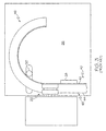
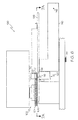
- FIG. 6 illustrates a device 100 for forming a flanged ring.
- the device 100 includes a first pair of opposed surfaces adapted to compress the elongated protrusion 56.
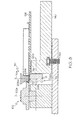
- the device 100 might include a first wheel 102 rotatable about a first rotation axis 102a and a second wheel 110 rotatable about a second rotation axis 110a that is parallel to the first rotational axis.
- the first pair of opposed surfaces comprises an outer peripheral surface of the first wheel 102 and an outer peripheral surface of the second wheel 110.
- the first wheel includes a first peripheral surface 104 including a first diameter and a second peripheral surface 106 including a second diameter that is less than the first diameter.
- the peripheral surface of the second wheel 110 might also include a first peripheral surface 112 including a first diameter and a second peripheral surfaces 114 including a second diamter that is greater than the first diameter of the first peripheral surface. Therefore, the first and second peripheral surface portions 104, 106 of the first wheel 102 are adapted to cooperate with the corresponding first and second surface portions 112, 114 of the second wheel 110 to form an offset in the elongated protrusion. Forming such an offset in the elongated protrusion facilitates shaping of the elongated protrusion as it is formed as part of the curved extension.
- portions of the peripheral surface of the first wheel 102 and/or the peripheral surface of the second wheel 110 might be knurled to facilitate gripping and elongation of the elongated protrusion as it is fed with respect to the device 100.
- the first peripheral surface 104 and the second peripheral surface 106 of the first wheel 102 might be knurled and the second peripheral surface 114 of the second wheel 110 might be knurled.
- the device 100 further includes a second pair of opposed surfaces adapted to compress the elongated base 52 of the flange 50 to increase the length of one portion of the elongated base relative to another portion of the elongated base.
- the device 100 can include a roller 120 including an outer peripheral surface, wherein one of the second pair of opposed surfaces comprises the outer peripheral surface 122 of the roller 120. Shown exaggerated in the figures for clarity, outer peripheral surface 122 the roller 120 might comprise a conical portion to provide increase compression force at an outer portion 206a than an inner portion 206b of the elongated base 206.
- the difference in compression force facilitates an increase in length of the outer portion 206a of the elongated base 206 relative to the inner portion 206b of the base 206 to form an elongated curved extension from the elongated straight flange as the elongated straight flange is fed with respect to the device 100.
- the second wheel 110 can include a bearing surface 116 that acts together with the outer peripheral surface 122 of the roller 120 to provide the second pair of opposed surfaces adapted to compress the elongated base 206.
- the bearing surface 116 comprises a substantially flat surface that is perpendicular to the rotational axis 110a of the second wheel 110.
- the rotational axis 120a of the roller 120 can also be perpendicular to the rotational axes 102a, 110a of the first and second wheel 102, 110.
- the exemplary roller 120 illustrated and described herein might be mounted for relative movement with respect to the support surface 126.
- the roller 120 is rotatably mounted on a lever arm 140.
- the lever arm 140 has a pivot axis 142 (see FIG. 6) and a jack screw 144 adapted to provide the appropriate angular adjustment between the lever arm 140 and the support surface 126.
- the conical shape of the outer peripheral surface 122 of the roller 120 might provide the appropriate structure.
- the rotational axis of the roller 120 might be adjustable to provide a desirable distribution of compressive forces.
- a method of making a flanged ring with the device 100 includes first providing an elongated straight flange with an elongated base and an elongated protrusion extending from the elongated base.
- the elongated straight flange might further comprise an elongated inner flange.
- the elongated straight flange 50 illustrated in FIGS. 4 and 5 might be provided.
- the elongated straight flange is fed with respect to the device 100 such that the first pair of opposed surfaces compress the elongated protrusion 56 to increase the length of the elongated protrusion and the second pair of opposed surfaces compress the elongated base 52 to increase the length of the outer portion of the base relative to the inner portion of the elongated base.
- a rotatable stop 130 might also be provided and initially adjusted prior to feeding the elongated straight flange with respect to the device to provide a predetermined radius to the elongated curved extension.
- An optional secondary guide 132 might also be provided to fine-tune the radius of the curved extension.
- the secondary guide 132 might include a set of three guide wheels rotatably mounted with respect to a lever arm.
- a squaring roll 160 might also be included to discourage helical twisting of the flange as it is fed through the first and second pair of opposed surfaces.
- the device 100 might also include an infeed guide roller 150 and guide blocks 148, 149.
- the guide roller 150 may be an idler roller or might also be driven to provide a controlled the feed rate of the elongated straight flange with respect to the device.
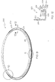
- FIGS. 9-12 An exemplary circular flanged ring 200 formed with the device 100 is illustrated in FIGS. 9-12.
- an elongated straight flange is fed with respect to the device 100 until the elongated curved extension follows an arc of at least about 360°. The ends of the curved extension may then be welded at a weld seam 204 to form the circular ring.
- the profile of the circular flanged ring 200 includes an elongated inner flange 218 extending from an elongated base 206 and an elongated protrusion 208 also extending from the elongated base 206.
- the elongated inner flange 218 might include an optional bead 220 that is conventionally provided with such profiles. In alternative embodiments, the optional bead 220 might not be provided.
- the elongated protrusion 208 includes an outer protrusion portion 210 and an inner protrusion portion 212 that, as described above, might optionally be folded inward with respect to the outer protrusion portion 210 as shown.
- the elongated protrusion 208 might also include a first portion 214 and a second portion 216 offset from the first portion 214 with a transition 215 section attaching the first portion 214 to the second portion 216 to permit the first and second portion to be concentric with respect to one another.
- the first portion 214 includes an outer surface portion 214a and the second portion 216 includes an outer surface portion 216a, wherein the outer surface portions 214a and 216a might be knurled as illustrated in FIGS. 9 and 11.
- the inner surface portion 214b of the first portion 214 might also include a knurled surfaces.
- FIGS. 13-16 An exemplary oval flanged ring 300 formed with the device 100 is illustrated in FIGS. 13-16.
- an elongated straight flange is fed with respect to the device 100 until the elongated curved extension follows an arc of at least about 180°.
- the elongated straight flange might be fed with respect to the device 100 until a substantial J-shaped flange portion 302 is formed as shown in FIG. 7A.
- the J-shaped portion 302 includes an elongated curved extension 304 and an elongated straight extension 306. Two such J-shaped portions might be fastened with respect to one another to form an exemplary oval-shaped flanged ring. For example, as shown in FIG.
- a first J-shaped flanged portion 302a is inverted with respect to a second J-shaped flanged portion 302b and welded at weld seams 310a, 310b to form the oval shaped flanged ring.
- the elongated curved extension 304 might include knurled surfaces.
- an outer surface 314a of the first portion and an outer surface 316a of the second portion might have a knurled surface as shown in FIG. 15.
- the inner surface 314b of the first portion might be knurled while the inner surface 316b of the second portion might not include a knurled surface.
- an outer surface 322a of the second portion of the elongated straight extension 306 might be knurled while the outer surface 320a and inner surface 320b of the first portion and the inner surface 322b of the second portion might not include knurled surfaces.
- the outer surface 322a might be knurled during the process of continuing to feed the J-shaped flange portion 302 with respect to the device 100 after sufficient compression has been removed to prevent further curving of the extension as it is being fed.
- oval-shaped includes a shape with end portions extending through 180° with straight segments attaching the end portions together.
- oval-shaped flanged rings might include rings that have an elliptical shape or egg shape.
- knurled surfaces might include any textured surface wherein one surface forms or cuts, such as stamps, an imprint on another surface.
Landscapes
- Engineering & Computer Science (AREA)
- Mechanical Engineering (AREA)
- Rolling Contact Bearings (AREA)
- Rolls And Other Rotary Bodies (AREA)
- Braking Arrangements (AREA)
Applications Claiming Priority (2)
| Application Number | Priority Date | Filing Date | Title |
|---|---|---|---|
| US57129404P | 2004-05-15 | 2004-05-15 | |
| US571294P | 2004-05-15 |
Publications (1)
| Publication Number | Publication Date |
|---|---|
| EP1595613A1 true EP1595613A1 (de) | 2005-11-16 |
Family
ID=34938271
Family Applications (1)
| Application Number | Title | Priority Date | Filing Date |
|---|---|---|---|
| EP05076125A Withdrawn EP1595613A1 (de) | 2004-05-15 | 2005-05-12 | Flanschring, Vorrichtung zu seiner Herstellung und Verfahren |
Country Status (4)
| Country | Link |
|---|---|
| US (1) | US7287407B2 (de) |
| EP (1) | EP1595613A1 (de) |
| JP (1) | JP2005349473A (de) |
| CA (1) | CA2507382C (de) |
Families Citing this family (3)
| Publication number | Priority date | Publication date | Assignee | Title |
|---|---|---|---|---|
| JP5393580B2 (ja) * | 2010-04-21 | 2014-01-22 | 本田技研工業株式会社 | 円弧状レールの製造方法 |
| ES2948109T3 (es) | 2015-06-30 | 2023-08-31 | Saint Gobain Performance Plastics Corp | Cojinete plano |
| CN118557876B (zh) * | 2024-07-31 | 2024-12-27 | 上海术之道医疗器械有限公司 | 微导管及微导管的控弯方法 |
Citations (5)
| Publication number | Priority date | Publication date | Assignee | Title |
|---|---|---|---|---|
| GB624169A (en) * | 1944-11-21 | 1949-05-30 | Sncase | Improvements in machines for bending angle and other metal rods, bars or the like |
| JPS5973125A (ja) * | 1982-10-21 | 1984-04-25 | Hitachi Ltd | 形材の圧延曲げ加工法 |
| JPS60115331A (ja) * | 1983-11-25 | 1985-06-21 | Hitachi Ltd | チャンネル材の圧延曲げ方法および装置 |
| EP0296317A2 (de) * | 1987-04-01 | 1988-12-28 | Späth GmbH & Co. KG Stahlbau-Biegetechnik | Verfahren und Vorrichtung zum Biegen eines Bleches |
| US20030025332A1 (en) * | 2001-08-02 | 2003-02-06 | Robert Issagholian-Havai | Method and apparatus for producing end flange member for cylindrical duct |
Family Cites Families (21)
| Publication number | Priority date | Publication date | Assignee | Title |
|---|---|---|---|---|
| US2826804A (en) * | 1958-03-18 | Spun metal manufacture | ||
| US2047084A (en) * | 1935-04-22 | 1936-07-07 | Kelsey Hayes Wheel Co | Method of forming brake shoes |
| US2093933A (en) * | 1935-05-13 | 1937-09-21 | Kelsey Hayes Wheel Co | Rolling machine |
| GB871733A (en) | 1959-04-16 | 1961-06-28 | John Oliver Creek | Mounting ring for blading in a gas turbine engine and method of making same |
| US3749425A (en) * | 1971-11-04 | 1973-07-31 | W Howland | Take-off duct coupler |
| US4041746A (en) * | 1975-07-07 | 1977-08-16 | Aspro, Inc. | Method of making V-grooved sheet metal pulleys |
| US4023250A (en) * | 1975-08-04 | 1977-05-17 | Aspro, Incorporated | Method and apparatus for making hubless V-grooved pulley and product |
| DE2626398C2 (de) * | 1976-06-12 | 1986-09-18 | Ina Waelzlager Schaeffler Kg, 8522 Herzogenaurach | Verfahren und Vorrichtung zum Herstellen eines Flachkäfigs für ein Axial-Wälzlager aus einem Flachkäfigband |
| GB1581386A (en) | 1977-05-11 | 1980-12-10 | Coil Protection Service | Method and apparatus for producing bent angel pieces |
| US4117704A (en) * | 1977-05-13 | 1978-10-03 | Societe Coil Protection Service | Method and apparatus for producing a bent angle piece from a sheet-metal |
| US4144732A (en) * | 1977-11-09 | 1979-03-20 | Master Craft Engineering, Inc. | Method and apparatus for forming one-piece pulleys |
| US4170888A (en) * | 1978-06-30 | 1979-10-16 | Motor Wheel Corporation | Apparatus for spin-forming wheel rims |
| US4361021A (en) * | 1980-05-05 | 1982-11-30 | United Mcgill Corporation | Method and apparatus for forming angle ring flanges |
| DE3143893C1 (de) * | 1981-11-05 | 1983-04-21 | Karl Meinig KG, 7201 Rietheim-Weilheim | Flanschring fuer Rohre |
| US4524595A (en) * | 1983-09-19 | 1985-06-25 | Kabushiki Kaisha Kanemitsu | Method of manufacturing sheet metal made poly-V pulleys |
| US4765167A (en) * | 1986-12-04 | 1988-08-23 | Koppy Corporation | Method of roll forming piston |
| US5456099A (en) * | 1992-03-19 | 1995-10-10 | Laser Products, Inc. | Method and apparatus for forming a side panel assembly |
| US5393106A (en) * | 1993-09-15 | 1995-02-28 | Casco Manufacturing | Sealed knock-down duct collar |
| US5983496A (en) * | 1996-03-15 | 1999-11-16 | J.A. Hermanson | Circular and oval flanged rings for connecting ducting and method of making |
| US6289706B1 (en) * | 1996-03-15 | 2001-09-18 | J. A. Hermanson | Circular and oval flanged rings for connecting ducting and method of making |
| US6644083B2 (en) * | 2000-06-19 | 2003-11-11 | Macdonald-Miller Incorporated | Spin forming a tubular workpiece to form a radial flange on a tubular flange and a bead or thick rim on the radial flange |
-
2005
- 2005-05-11 US US11/126,753 patent/US7287407B2/en not_active Expired - Lifetime
- 2005-05-12 EP EP05076125A patent/EP1595613A1/de not_active Withdrawn
- 2005-05-13 CA CA2507382A patent/CA2507382C/en not_active Expired - Fee Related
- 2005-05-16 JP JP2005142814A patent/JP2005349473A/ja active Pending
Patent Citations (5)
| Publication number | Priority date | Publication date | Assignee | Title |
|---|---|---|---|---|
| GB624169A (en) * | 1944-11-21 | 1949-05-30 | Sncase | Improvements in machines for bending angle and other metal rods, bars or the like |
| JPS5973125A (ja) * | 1982-10-21 | 1984-04-25 | Hitachi Ltd | 形材の圧延曲げ加工法 |
| JPS60115331A (ja) * | 1983-11-25 | 1985-06-21 | Hitachi Ltd | チャンネル材の圧延曲げ方法および装置 |
| EP0296317A2 (de) * | 1987-04-01 | 1988-12-28 | Späth GmbH & Co. KG Stahlbau-Biegetechnik | Verfahren und Vorrichtung zum Biegen eines Bleches |
| US20030025332A1 (en) * | 2001-08-02 | 2003-02-06 | Robert Issagholian-Havai | Method and apparatus for producing end flange member for cylindrical duct |
Non-Patent Citations (2)
| Title |
|---|
| PATENT ABSTRACTS OF JAPAN vol. 008, no. 180 (M - 318) 18 August 1984 (1984-08-18) * |
| PATENT ABSTRACTS OF JAPAN vol. 009, no. 268 (M - 424) 25 October 1985 (1985-10-25) * |
Also Published As
| Publication number | Publication date |
|---|---|
| JP2005349473A (ja) | 2005-12-22 |
| CA2507382A1 (en) | 2005-11-15 |
| US7287407B2 (en) | 2007-10-30 |
| US20050268686A1 (en) | 2005-12-08 |
| CA2507382C (en) | 2011-09-13 |
Similar Documents
| Publication | Publication Date | Title |
|---|---|---|
| CA2967914C (en) | Method of producing steel pipe and press die used for same | |
| CN110182108A (zh) | 斜倚器保持环及其制造方法 | |
| EP1797972A1 (de) | Rohrelement, Verfahren zur dessen Herstellung, sowie eine daraus hergestellte Rolle | |
| EP3597322B1 (de) | Presswerkzeug und verfahren zur herstellung von stahlrohren | |
| CA2507382C (en) | Flanged ring and device adapted to form a flanged ring and methods | |
| EP1645403A1 (de) | Verfahren und Vorrichtung zur Herstellung eines Reifenwulstes | |
| US7107682B2 (en) | Method for manufacturing tubes and profiles | |
| CN1286589C (zh) | 弯管机工件截面形状的矫正方法 | |
| JPH09234511A (ja) | 金属製巻きパイプの製造方法及びその装置 | |
| EP1108526B1 (de) | Verfahren und Vorrichtung zur Herstellung einer schlauchförmigen Verstärkungslage für einen Reifen | |
| JP2005504674A (ja) | ランフラット用ホイールのためのランフラット用支持体を製造する方法 | |
| US4603807A (en) | Mill for roll forming a fluted tube | |
| CN110520311A (zh) | 带有球颈和联结球的挂车联结器以及用于其制造的方法 | |
| CN102615843B (zh) | 充气轮胎的制造方法 | |
| JPS59185532A (ja) | 車輪リムの製造方法 | |
| JPH0647472A (ja) | コイル材の金属パイプを用いたステアリングホイール芯金用のリング成型方法及びその装置 | |
| CN214290224U (zh) | 冷风机的蒸发器所用铜管的弯管机 | |
| CN1517239A (zh) | 具有空心凸缘部的轮辋的制造方法 | |
| US7775076B2 (en) | Pinch-point lock-seam tubing, pinch point seaming devices, and methods for manufacturing stabilized lock-seam tubing | |
| TWI574752B (zh) | A method of manufacturing a steel sheet having a cross-sectional shape in the direction of the long side and a roll forming apparatus | |
| JPS59125214A (ja) | 管成形法 | |
| CN112638558B (zh) | 钢管的制造方法及冲压模具 | |
| JPH021564B2 (de) | ||
| JPH10508538A (ja) | 螺旋状の製品を製造するための方法と装置 | |
| CN222115425U (zh) | 台球杆调直器 |
Legal Events
| Date | Code | Title | Description |
|---|---|---|---|
| PUAI | Public reference made under article 153(3) epc to a published international application that has entered the european phase |
Free format text: ORIGINAL CODE: 0009012 |
|
| AK | Designated contracting states |
Kind code of ref document: A1 Designated state(s): AT BE BG CH CY CZ DE DK EE ES FI FR GB GR HU IE IS IT LI LT LU MC NL PL PT RO SE SI SK TR |
|
| AX | Request for extension of the european patent |
Extension state: AL BA HR LV MK YU |
|
| 17P | Request for examination filed |
Effective date: 20060116 |
|
| AKX | Designation fees paid |
Designated state(s): AT BE BG CH CY CZ DE DK EE ES FI FR GB GR HU IE IS IT LI LT LU MC NL PL PT RO SE SI SK TR |
|
| 17Q | First examination report despatched |
Effective date: 20060724 |
|
| 17Q | First examination report despatched |
Effective date: 20060724 |
|
| GRAP | Despatch of communication of intention to grant a patent |
Free format text: ORIGINAL CODE: EPIDOSNIGR1 |
|
| RTI1 | Title (correction) |
Free format text: DEVICE ADAPTED TO FORM A FLANGED RING AND METHOD |
|
| STAA | Information on the status of an ep patent application or granted ep patent |
Free format text: STATUS: THE APPLICATION IS DEEMED TO BE WITHDRAWN |
|
| 18D | Application deemed to be withdrawn |
Effective date: 20071005 |