EP1594201A1 - Gleitfunkenzündkerze mit mehreren Funken - Google Patents
Gleitfunkenzündkerze mit mehreren Funken Download PDFInfo
- Publication number
- EP1594201A1 EP1594201A1 EP05300358A EP05300358A EP1594201A1 EP 1594201 A1 EP1594201 A1 EP 1594201A1 EP 05300358 A EP05300358 A EP 05300358A EP 05300358 A EP05300358 A EP 05300358A EP 1594201 A1 EP1594201 A1 EP 1594201A1
- Authority
- EP
- European Patent Office
- Prior art keywords
- electrode
- insulating body
- counter
- electrodes
- high voltage
- Prior art date
- Legal status (The legal status is an assumption and is not a legal conclusion. Google has not performed a legal analysis and makes no representation as to the accuracy of the status listed.)
- Granted
Links
- 230000003321 amplification Effects 0.000 claims abstract description 5
- 238000003199 nucleic acid amplification method Methods 0.000 claims abstract description 5
- 230000005684 electric field Effects 0.000 claims abstract description 3
- 238000002485 combustion reaction Methods 0.000 claims description 12
- 239000002184 metal Substances 0.000 claims description 8
- 239000008188 pellet Substances 0.000 claims description 3
- 230000002093 peripheral effect Effects 0.000 description 10
- 230000000694 effects Effects 0.000 description 9
- 238000004519 manufacturing process Methods 0.000 description 5
- 239000000446 fuel Substances 0.000 description 4
- 230000037431 insertion Effects 0.000 description 4
- 238000003780 insertion Methods 0.000 description 4
- 238000009413 insulation Methods 0.000 description 4
- 239000000203 mixture Substances 0.000 description 4
- 230000015556 catabolic process Effects 0.000 description 3
- 239000000463 material Substances 0.000 description 3
- 230000005686 electrostatic field Effects 0.000 description 2
- 239000012212 insulator Substances 0.000 description 2
- 208000031968 Cadaver Diseases 0.000 description 1
- 230000015572 biosynthetic process Effects 0.000 description 1
- 230000009172 bursting Effects 0.000 description 1
- 239000000919 ceramic Substances 0.000 description 1
- 230000006866 deterioration Effects 0.000 description 1
- 230000002349 favourable effect Effects 0.000 description 1
- 230000000977 initiatory effect Effects 0.000 description 1
- 230000010354 integration Effects 0.000 description 1
- 238000003754 machining Methods 0.000 description 1
- 230000000873 masking effect Effects 0.000 description 1
- 210000002445 nipple Anatomy 0.000 description 1
- 238000007789 sealing Methods 0.000 description 1
- 238000005728 strengthening Methods 0.000 description 1
- 230000003313 weakening effect Effects 0.000 description 1
Images
Classifications
-
- H—ELECTRICITY
- H01—ELECTRIC ELEMENTS
- H01T—SPARK GAPS; OVERVOLTAGE ARRESTERS USING SPARK GAPS; SPARKING PLUGS; CORONA DEVICES; GENERATING IONS TO BE INTRODUCED INTO NON-ENCLOSED GASES
- H01T13/00—Sparking plugs
- H01T13/52—Sparking plugs characterised by a discharge along a surface
-
- H—ELECTRICITY
- H01—ELECTRIC ELEMENTS
- H01T—SPARK GAPS; OVERVOLTAGE ARRESTERS USING SPARK GAPS; SPARKING PLUGS; CORONA DEVICES; GENERATING IONS TO BE INTRODUCED INTO NON-ENCLOSED GASES
- H01T13/00—Sparking plugs
- H01T13/46—Sparking plugs having two or more spark gaps
- H01T13/467—Sparking plugs having two or more spark gaps in parallel connection
Definitions
- the invention relates to a spark plug having a surface effect with sparks, intended in particular to equip a breech of internal combustion engine of a motor vehicle. It relates to also a cylinder head provided with such a candle.
- the invention more particularly relates to a candle effect of surface, that is to say using the effects of amplification of the field in the vicinity of an insulating surface.
- Document FR 2 816 119 describes a surface effect candle to direct the spark radially relative to the axis of the candle which prevents the candle from obscuring part of the room with spark.
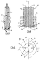
- FIG. 1 A model of surface candle described in this document is shown in Figure 1.
- the candle is shaped to present a symmetry of revolution around its longitudinal axis. She understands a cylindrical electrode 1 electrically connected to ground, which serves as metal base. This base surrounds a high voltage electrode 2 of cylindrical shape arranged in central position.
- the central electrode 2 is isolated from the base 1 via an insulating sleeve 3 of substantially cylindrical shape.
- the lower end of the sleeve 3 has a circular flange shape 4 of greater diameter than rest of the sleeve.
- the flange 4 cooperates on one of its sides with a counter-electrode 5 in the form of a dish, which can be embedded in the sleeve, its opposite side having a surface 6 facing the combustion chamber.
- the extreme part of the electrode controls 2 has a radially flared shape 7 which crowns the sleeve 3.
- the electrostatic field in the vicinity of surface 6 is then amplified by the counter electrode 5 connected to the ground electrode.
- This candle is called radial spark surface candle in the measure or spark is created on the surface 6 of the insulation, according to a direction substantially perpendicular to the axis of the candle.
- the flange-shaped portion 4 of such a candle must have a small thickness to allow good amplification of the electrostatic field at the surface of the insulator and a voltage of weak breakdown. This small thickness weakens it, which requires a precise mounting and low tolerance of machining parts for avoid the application of mechanical stresses on the flange.
- a mounting of the candle directly into the base or breech, during the foundry of these pieces leads to a frequent rupture of the collar during manufacture or weakening that can lead to the deterioration of the candle later.
- the life of these candles once integrated into the cylinder head is therefore clearly insufficient. It is indeed not conceivable to change the breech because of a faulty candle.
- Such a candle also has the disadvantage of not being able to direct the spark in a predetermined direction, which may originate anywhere on the edge of the candle, and especially in a opposite direction to the air / fuel mixture, moreover, the generation a single spark is not always sufficient to obtain a good ignition efficiency.
- the aim of the invention is to overcome these disadvantages by proposing a surface effect candle capable of generating multiple spark simultaneously in predetermined directions and whose insulation has a better mechanical resistance.
- the candle according to the invention can further be manufactured at low cost with tolerances higher. It is particularly well suited for use integrated into the cylinder head, but not limited to
- a first object of the invention relates to a candle surface-effect ignition device formed of an insulating body and provided with a earth electrode, in which the insulating body extends into a preferred direction D and ends with an end face substantially flat which extends in a plane P crossed by the direction D, characterized in that, in the direction D, the insulating body is crossed on its periphery by at least two electrodes fed with high voltage with a spur-shaped end protruding from the face end of the insulating body, each lug extending in a predetermined direction E substantially parallel to the plane P, and in that for each high-voltage electrode, a counter-electrode connected to the mass is inserted into the insulating body, its end being localized substantially perpendicular to the pin of the high-voltage electrode corresponding to generate sufficient amplification of the electric field at the end of the pin to make a spring spark to the ground electrode when applying a high voltage at the high voltage electrode.
- sparks are produced simultaneously with a high voltage electrode spark, these sparks being generated along privileged directions along the surface end of the insulating body, while strengthening the mechanical strength of the insulating body.
- the constraints are indeed localized around counter-electrodes in a small part of the insulating body whose mechanical strength is thus increased and whose service life can reach that of the vehicle, allowing its definitive integration into the cylinder head.
- the generation of several sparks makes it possible to obtain a initial volume ignited much larger than with a single spark, thus improving the efficiency of the candle.
- sparks are generated in privileged directions allows in in addition to getting an ignited volume in substantially the same place at each ignition, for example near the arrival of the mixture air / fuel from an engine.
- the pins of the electrodes high voltage are directed to the outside of the insulator body, the electrode of mass surrounds the insulating body, and the ends of the counter-electrodes distant from the pins are in contact with the electrode of mass.
- the sparks are then generated towards the outside of the candle, from the high voltage electrodes to the ground electrode along the end surface of the insulating body.
- the pins of the electrodes high voltage are directed towards the inside of the insulating body, the mass passes through the insulating body in the direction (D) near the center of the insulating body and protrudes from the end face of the body, and the ends of the counter-electrodes distant pins are connected to the ground electrode. Sparks are generated from the electrodes high voltage to the ground electrode in the center of the candle.
- the central position of the ground electrode allows to distribute the high voltage electrodes regularly on the entire periphery of the body insulating. The central electrode is then connected to the ground by a wiring externally at the upper end of the candle.
- the lugs of the electrodes high voltage are directed towards the inside of the insulating body, the mass has one end connected to the radially projecting mass of insulating body and another projecting end of the end face in the direction D, and the ends of the remote counter-electrodes pins are connected to the ground electrode.
- the sparks are then generated towards the center of the candle in the same way as in the previous embodiment.
- said at least one counter-electrode is substantially bar-shaped or wire-shaped and / or substantially parallel to a lug. This configuration makes it easier to insertion into the insulating body of the candle while reducing stresses exerted by the counter-electrode on the insulating body surrounding.
- said at least one lug has a shape elongated tapered towards its end. Such a form allows create a peak effect that promotes spark formation at the end ergot and limiting the wear of the latter.
- the ground electrode is formed by the cylinder head of an internal combustion engine, and each counter-electrode, or the ground electrode, is in contact with, or partially embedded in said cylinder head.
- a metallic base surrounding the insulating body forms the ground electrode, or is connected to ground, and each counter electrode, or the ground electrode, is in contact with, or partially drowned in the pellet.
- the candle comprises between two and six electrodes high tension.
- the number of high voltage electrodes is however chosen according to the space available in the room of combustion of an internal combustion engine and the cost of production given that a high voltage coil is needed for each high voltage electrode.
- Another object of the invention relates to a cylinder head for combustion of a motor vehicle, comprising at least one candle according to the invention.
- a candle 10 comprises at least two peripheral electrodes 11, at each of which will be applied a high voltage, surrounded by an insulating body 12 made of a material whose dielectric coefficient is greater to one, for example ceramics.
- the electrodes 11 and the insulating body 12 extend in the same privileged direction D.
- the insulating body is cylindrical and the electrodes 11 are distributed near the periphery of the insulating body.
- the insulating body 12 presents a symmetry of revolution whose axis is parallel to the direction D.
- the insulating body has an end face 13 substantially flat, along which sparks can spread.
- This end face 13 extends in a plane P traversed by direction D.
- This plane P is perpendicular to the plane of the sheet of FIGS. 2, 4 and 6.
- the direction D may be slightly inclined relative to the normal to plane P-
- the angle of inclination between plane P and direction D will then be determined according to the inclination of the candle by ratio below the breech in which it is to be inserted.
- the little space available above the cylinder head requires the inclined insertion of the candle with respect to the axis of the yoke, the end face 13 being placed substantially in the extension of the bottom surface of the cylinder head.
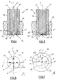
- Each peripheral electrode 11 has a rod shape cylindrical whose lower end has a lug 14 which makes protruding from the end face 13 of the insulating body ( Figures 2, 4, 6). This lug 14 extends in a direction E secant direction D. It has a tapered shape towards its free end so to limit its wear.
- Each peripheral electrode 11 is inserted into the insulating body, for example during its manufacture, so that the ergot 14 is pressed against the end face 13 of the insulating body and extends thus substantially in the same plane as this one. This position of each lug in contact with the end face of the insulating body allows to reduce the bursting voltage of the candle.
- the electrodes 11 can be inserted into holes drilled in the insulating body 12. These holes are for example regularly distributed near the periphery of the insulating body, following a regular polygon.
- the number of electrodes 11 may be of the order of two to six, depending on the desired size of the candle 10.
- each counter-electrode 15 associated with each peripheral electrode 11 is inserted into the body 12.
- the end of each counter-electrode is located substantially vertically above the end of the corresponding lug 14, and its other end is connected to a ground electrode, so the position of the end of this counter-electrode in line with the ergot allows the generation of a spark at the end of the pin.
- the counter-electrode 15 it suffices that it occupies only one low volume of the insulating body, provided that its end is substantially in line with the end of the lug.
- the counter-electrode 15 has an elongated shape of small dimensions relative to the section of the insulating body. It is, for example, symmetrical, in the form of a cylindrical bar or a wire of small diameter extending substantially parallel to the lug 14 at a distance d from the latter in the direction D.
- the dimensions of each counter-electrode are chosen according to congestion and to reduce mechanical stress and improve the stability of the spark. Their diameter can vary from a few microns to a few millimeters.
- the distance d is not too high in order to limit the breakdown voltage, for example of the order of 1.5 to 2 mm for a breakdown voltage of the order of 18 kV under pressure.
- Each counter-electrode 15 can be inserted into the insulating body 12 during the manufacture thereof, for example by overmolding in the material forming the insulating body, either after manufacture in piercing an orifice in the wall of the insulating body adapted to receive it. The mechanical stresses are then localized around each counter-electrode small dimensions.
- a first embodiment of the candle is described in reference to FIGS. 2 and 3.
- the present candle four peripheral electrodes 11 regularly distributed nearby from the periphery of the candle.
- the lugs 14 of these electrodes are radially outwardly of the insulating body, in the direction of the ground electrode 16 which is formed by the engine cylinder head surrounding the candle.
- each counterelectrode 15 and the yoke 16 In order to ensure a close contact between each counterelectrode 15 and the yoke 16, the end of each counter-electrode 15 distant from a pin 14 protrudes from the insulating body 12 ct is embedded in the metal forming the cylinder head 16 ( Figures 2, 3). This configuration is for example obtained by overmolding the candle in the metal.
- the electrode of mass 16 may be formed by a metal base overmolded on the candle, each counter-electrode 15 flush with the surface of the body insulation coming into contact with the base connected to the ground, or a protruding part of each counter-electrode being embedded in the metal of the pellet.
- a second embodiment of the candle is described in reference to Figures 4 and 5. This example differs from the previous one by the orientation of the lugs of the peripheral electrodes 11, which are directed towards the center of the candle, as well as by the position of the counter-electrodes and the structure of the ground electrode.
- the ground electrode 17 is formed of a central electrode in rod shape passing through the insulating body 12 substantially according to the direction D, in the center of the candle.
- the lower end 18 of this electrode protrudes from the end face of the candle 13. This lower end, in the form of nipple 18, opens out of the face end tightly.
- the other end of the electrode ground is connected to the ground by a wiring not shown.
- Counter electrodes 15 are embedded in the material of the insulating body and placed radially along the direction E of each pin, so as to form a star. The ends of the counter-electrodes distant from the lugs are connected to the ground electrode 17.
- a metal cap surrounding the insulating body 12 can be expected.
- the peripheral electrodes 11 are always directed towards the center of the candle, but the ground electrode 19 is formed of a conductive rod L-shape. Part of this rod extends radially and its end is in contact with the cylinder head 16 surrounding the candle, connected to the mass. The other part of this rod extends substantially in the center of the latter in the direction D and its end 18 protrudes so sealing of the end surface 13 of the insulating body.
- the extremities counter-electrodes 15 distant from the lugs then meet at the center of the candle and are connected to this conductive rod 19.
- the candle may comprise a metal cap connected to the mass, surrounding the insulating body of the candle, with which the rod conductive 19 is in contact.
- the field electrostatic peak is in the space between the extremities each lug 14 ct of the earth electrode 16, 17 or 19 so that a spark can be formed at the end of the pin 14.
- the presence a spark changes the architecture of field lines electrostatic so that every spark will move parallel to a counter electrode 15 away from the lug 14, the along the surface of the end face 13. If the counter-electrode 15 has a sufficiently small section, the spark is stabilized in direction and position in space, which allows him to occupy the same position in the combustion chamber at each ignition.
- the generation of several sparks promotes good stability of cycle-to-cycle combustion and increased favorable combustion rate the reduction of rattling, always very embarrassing especially in supercharged engines.
- the candle according to the invention can be advantageously used for a classic arrangement of central candle in the cylinder head, for a combustion chamber with four valves per cylinder, but without limit yourself.
- the insulating body of the candle may not be cylindrical and have a smaller surface area given that the electrodes and counter electrodes do not extend over the entire periphery of the insulating body. Such a reduction of the body section insulation has the advantage of reducing the bulk of the candle and facilitate insertion into a breech.
Landscapes
- Spark Plugs (AREA)
Applications Claiming Priority (2)
| Application Number | Priority Date | Filing Date | Title |
|---|---|---|---|
| FR0404940A FR2870052B1 (fr) | 2004-05-07 | 2004-05-07 | Bougie d'allumage a effet de surface a etincelles multiples |
| FR0404940 | 2004-05-07 |
Publications (2)
| Publication Number | Publication Date |
|---|---|
| EP1594201A1 true EP1594201A1 (de) | 2005-11-09 |
| EP1594201B1 EP1594201B1 (de) | 2007-07-11 |
Family
ID=34942597
Family Applications (1)
| Application Number | Title | Priority Date | Filing Date |
|---|---|---|---|
| EP20050300358 Expired - Lifetime EP1594201B1 (de) | 2004-05-07 | 2005-05-04 | Gleitfunkenzündkerze mit mehreren Funken |
Country Status (3)
| Country | Link |
|---|---|
| EP (1) | EP1594201B1 (de) |
| DE (1) | DE602005001573T2 (de) |
| FR (1) | FR2870052B1 (de) |
Cited By (1)
| Publication number | Priority date | Publication date | Assignee | Title |
|---|---|---|---|---|
| WO2008017601A1 (de) * | 2006-08-08 | 2008-02-14 | Siemens Aktiengesellschaft | Zündkerze für hochfrequenzplasmazündung |
Families Citing this family (4)
| Publication number | Priority date | Publication date | Assignee | Title |
|---|---|---|---|---|
| JP4760780B2 (ja) * | 2007-06-13 | 2011-08-31 | 株式会社デンソー | プラズマ式点火装置 |
| DE102009036732A1 (de) | 2009-08-08 | 2011-02-10 | Daimler Ag | Zündkerze |
| US9441604B2 (en) | 2012-09-18 | 2016-09-13 | Ming Zheng | Multi-coil spark ignition system |
| RO135550A2 (ro) | 2020-08-10 | 2022-02-28 | Universitatea Tehnică "Gheorghe Asachi" Din Iaşi | Bujie cu descărcare dublă |
Citations (2)
| Publication number | Priority date | Publication date | Assignee | Title |
|---|---|---|---|---|
| FR2792374A1 (fr) * | 1999-04-15 | 2000-10-20 | Renault | Dispositif d'allumage pour moteur a combustion interne et bougie d'allumage pour sa mise en oeuvre |
| FR2816119A1 (fr) * | 2000-10-27 | 2002-05-03 | Renault | Bougie a effet de surface a etincelle radiale |
-
2004
- 2004-05-07 FR FR0404940A patent/FR2870052B1/fr not_active Expired - Fee Related
-
2005
- 2005-05-04 DE DE602005001573T patent/DE602005001573T2/de not_active Expired - Lifetime
- 2005-05-04 EP EP20050300358 patent/EP1594201B1/de not_active Expired - Lifetime
Patent Citations (2)
| Publication number | Priority date | Publication date | Assignee | Title |
|---|---|---|---|---|
| FR2792374A1 (fr) * | 1999-04-15 | 2000-10-20 | Renault | Dispositif d'allumage pour moteur a combustion interne et bougie d'allumage pour sa mise en oeuvre |
| FR2816119A1 (fr) * | 2000-10-27 | 2002-05-03 | Renault | Bougie a effet de surface a etincelle radiale |
Cited By (1)
| Publication number | Priority date | Publication date | Assignee | Title |
|---|---|---|---|---|
| WO2008017601A1 (de) * | 2006-08-08 | 2008-02-14 | Siemens Aktiengesellschaft | Zündkerze für hochfrequenzplasmazündung |
Also Published As
| Publication number | Publication date |
|---|---|
| DE602005001573D1 (de) | 2007-08-23 |
| DE602005001573T2 (de) | 2008-03-13 |
| FR2870052B1 (fr) | 2006-06-23 |
| EP1594201B1 (de) | 2007-07-11 |
| FR2870052A1 (fr) | 2005-11-11 |
Similar Documents
| Publication | Publication Date | Title |
|---|---|---|
| EP2628220B1 (de) | Kurzschlussschutz bei einer hf-zündkerze | |
| FR2919965B1 (fr) | Bougie d'allumage a profileur d'ecoulements pour donner a un tourbillon transversal la forme d'ecoulements voulue dans une chambre de combustion | |
| FR2459563A1 (fr) | Bougie d'allumage a jet de plasma | |
| FR2831243A1 (fr) | Bougie de prechauffage pour un moteur diesel et procede de fabrication associe | |
| FR2847731A1 (fr) | Bougie d'allumage et procede pour sa fabrication | |
| EP1594201B1 (de) | Gleitfunkenzündkerze mit mehreren Funken | |
| EP2210079B1 (de) | Vergaservorrichtung mit eingebautem verbrennungssensor | |
| FR2865264A1 (fr) | Bougie de prechauffage et procede de fabrication d'une telle bougie | |
| WO2005040681A1 (fr) | Bougie de prechauffage comprenant un capteur de pression et moteur ainsi equipe | |
| FR2862347A1 (fr) | Culasse de moteur a combustion interne et bougie d'allumage | |
| FR2893455A1 (fr) | Bougie d'allumage pour moteur a combustion interne | |
| EP1202411B1 (de) | Gleitentladungszündkerze mit radialem Funken | |
| FR2862445A1 (fr) | Bougie d'allumage possedant une pluralite d'electrodes centrales | |
| FR2853461A1 (fr) | Bougie d'allumage a pointes multiples | |
| FR2890247A1 (fr) | Bougie d'allumage plasma pour un moteur a combustion interne | |
| EP1747403A1 (de) | Glühkerzenkopf und entsprechender piezoelektrischer drucksensor | |
| EP1526618A1 (de) | Gleitfunkenzündkerze mit gerichtetem Funken | |
| FR2894724A1 (fr) | Dispositif pour l'indexation angulaire d'une bougie de moteur a combustion | |
| FR2949539A1 (fr) | Bougie de prechauffage integrant un capteur de temperature et son procede de fabrication | |
| EP2559119B1 (de) | Zündkerze mit vorrichtung zur vermeidung von kurzschlüssen | |
| FR2860351A1 (fr) | Bougie d'allumage a bout de metal precieux | |
| FR3021096A1 (fr) | Bougie de prechauffage et son procede de fabrication | |
| WO2014086798A1 (fr) | Bougie de préchauffage de moteur diesel | |
| FR2949538A1 (fr) | Bougie de prechauffage et procede de fabrication d'une telle bougie | |
| WO2006136742A1 (fr) | Bougie d'allumage pour moteur a combustion interne |
Legal Events
| Date | Code | Title | Description |
|---|---|---|---|
| PUAI | Public reference made under article 153(3) epc to a published international application that has entered the european phase |
Free format text: ORIGINAL CODE: 0009012 |
|
| AK | Designated contracting states |
Kind code of ref document: A1 Designated state(s): AT BE BG CH CY CZ DE DK EE ES FI FR GB GR HU IE IS IT LI LT LU MC NL PL PT RO SE SI SK TR |
|
| AX | Request for extension of the european patent |
Extension state: AL BA HR LV MK YU |
|
| 17P | Request for examination filed |
Effective date: 20060501 |
|
| GRAP | Despatch of communication of intention to grant a patent |
Free format text: ORIGINAL CODE: EPIDOSNIGR1 |
|
| AKX | Designation fees paid |
Designated state(s): DE ES GB IT |
|
| GRAS | Grant fee paid |
Free format text: ORIGINAL CODE: EPIDOSNIGR3 |
|
| GRAA | (expected) grant |
Free format text: ORIGINAL CODE: 0009210 |
|
| AK | Designated contracting states |
Kind code of ref document: B1 Designated state(s): DE ES GB IT |
|
| REG | Reference to a national code |
Ref country code: GB Ref legal event code: FG4D Free format text: NOT ENGLISH |
|
| REF | Corresponds to: |
Ref document number: 602005001573 Country of ref document: DE Date of ref document: 20070823 Kind code of ref document: P |
|
| GBT | Gb: translation of ep patent filed (gb section 77(6)(a)/1977) |
Effective date: 20070814 |
|
| PG25 | Lapsed in a contracting state [announced via postgrant information from national office to epo] |
Ref country code: ES Free format text: LAPSE BECAUSE OF FAILURE TO SUBMIT A TRANSLATION OF THE DESCRIPTION OR TO PAY THE FEE WITHIN THE PRESCRIBED TIME-LIMIT Effective date: 20071022 |
|
| PLBE | No opposition filed within time limit |
Free format text: ORIGINAL CODE: 0009261 |
|
| STAA | Information on the status of an ep patent application or granted ep patent |
Free format text: STATUS: NO OPPOSITION FILED WITHIN TIME LIMIT |
|
| 26N | No opposition filed |
Effective date: 20080414 |
|
| PGFP | Annual fee paid to national office [announced via postgrant information from national office to epo] |
Ref country code: GB Payment date: 20110520 Year of fee payment: 7 |
|
| PGFP | Annual fee paid to national office [announced via postgrant information from national office to epo] |
Ref country code: IT Payment date: 20110523 Year of fee payment: 7 Ref country code: DE Payment date: 20110520 Year of fee payment: 7 |
|
| GBPC | Gb: european patent ceased through non-payment of renewal fee |
Effective date: 20120504 |
|
| PG25 | Lapsed in a contracting state [announced via postgrant information from national office to epo] |
Ref country code: IT Free format text: LAPSE BECAUSE OF NON-PAYMENT OF DUE FEES Effective date: 20120504 |
|
| REG | Reference to a national code |
Ref country code: DE Ref legal event code: R119 Ref document number: 602005001573 Country of ref document: DE Effective date: 20121201 |
|
| PG25 | Lapsed in a contracting state [announced via postgrant information from national office to epo] |
Ref country code: GB Free format text: LAPSE BECAUSE OF NON-PAYMENT OF DUE FEES Effective date: 20120504 |
|
| PG25 | Lapsed in a contracting state [announced via postgrant information from national office to epo] |
Ref country code: DE Free format text: LAPSE BECAUSE OF NON-PAYMENT OF DUE FEES Effective date: 20121201 |