EP1594145A1 - Wärmebehandlungssystem - Google Patents
Wärmebehandlungssystem Download PDFInfo
- Publication number
- EP1594145A1 EP1594145A1 EP04708855A EP04708855A EP1594145A1 EP 1594145 A1 EP1594145 A1 EP 1594145A1 EP 04708855 A EP04708855 A EP 04708855A EP 04708855 A EP04708855 A EP 04708855A EP 1594145 A1 EP1594145 A1 EP 1594145A1
- Authority
- EP
- European Patent Office
- Prior art keywords
- heat treatment
- magnetic field
- field generating
- treatment
- generating device
- Prior art date
- Legal status (The legal status is an assumption and is not a legal conclusion. Google has not performed a legal analysis and makes no representation as to the accuracy of the status listed.)
- Granted
Links
- 238000010438 heat treatment Methods 0.000 title claims abstract description 143
- 239000012298 atmosphere Substances 0.000 claims description 16
- 230000001590 oxidative effect Effects 0.000 claims description 11
- 238000001816 cooling Methods 0.000 claims description 10
- 239000012300 argon atmosphere Substances 0.000 claims description 2
- 239000012299 nitrogen atmosphere Substances 0.000 claims description 2
- 238000009434 installation Methods 0.000 abstract description 5
- 230000002093 peripheral effect Effects 0.000 description 12
- 239000010408 film Substances 0.000 description 10
- 239000000696 magnetic material Substances 0.000 description 8
- 235000012431 wafers Nutrition 0.000 description 8
- PNEYBMLMFCGWSK-UHFFFAOYSA-N aluminium oxide Inorganic materials [O-2].[O-2].[O-2].[Al+3].[Al+3] PNEYBMLMFCGWSK-UHFFFAOYSA-N 0.000 description 7
- IJGRMHOSHXDMSA-UHFFFAOYSA-N Atomic nitrogen Chemical compound N#N IJGRMHOSHXDMSA-UHFFFAOYSA-N 0.000 description 6
- 239000000428 dust Substances 0.000 description 6
- VYPSYNLAJGMNEJ-UHFFFAOYSA-N Silicium dioxide Chemical compound O=[Si]=O VYPSYNLAJGMNEJ-UHFFFAOYSA-N 0.000 description 5
- 239000007789 gas Substances 0.000 description 5
- 230000001965 increasing effect Effects 0.000 description 5
- 238000000034 method Methods 0.000 description 5
- XKRFYHLGVUSROY-UHFFFAOYSA-N Argon Chemical compound [Ar] XKRFYHLGVUSROY-UHFFFAOYSA-N 0.000 description 4
- 229910001873 dinitrogen Inorganic materials 0.000 description 4
- 239000000463 material Substances 0.000 description 3
- 229910052751 metal Inorganic materials 0.000 description 3
- 239000002184 metal Substances 0.000 description 3
- 229910001120 nichrome Inorganic materials 0.000 description 3
- 238000007789 sealing Methods 0.000 description 3
- 239000010935 stainless steel Substances 0.000 description 3
- 229910001220 stainless steel Inorganic materials 0.000 description 3
- 239000010409 thin film Substances 0.000 description 3
- XLYOFNOQVPJJNP-UHFFFAOYSA-N water Substances O XLYOFNOQVPJJNP-UHFFFAOYSA-N 0.000 description 3
- 238000004804 winding Methods 0.000 description 3
- 229910001030 Iron–nickel alloy Inorganic materials 0.000 description 2
- 229910045601 alloy Inorganic materials 0.000 description 2
- 239000000956 alloy Substances 0.000 description 2
- 229910052786 argon Inorganic materials 0.000 description 2
- 239000011449 brick Substances 0.000 description 2
- 239000000919 ceramic Substances 0.000 description 2
- 239000012809 cooling fluid Substances 0.000 description 2
- 239000003989 dielectric material Substances 0.000 description 2
- 239000000835 fiber Substances 0.000 description 2
- 230000006698 induction Effects 0.000 description 2
- 230000003993 interaction Effects 0.000 description 2
- 238000009940 knitting Methods 0.000 description 2
- BASFCYQUMIYNBI-UHFFFAOYSA-N platinum Chemical compound [Pt] BASFCYQUMIYNBI-UHFFFAOYSA-N 0.000 description 2
- 238000004544 sputter deposition Methods 0.000 description 2
- 239000000758 substrate Substances 0.000 description 2
- 229910020598 Co Fe Inorganic materials 0.000 description 1
- 229910002519 Co-Fe Inorganic materials 0.000 description 1
- 238000010276 construction Methods 0.000 description 1
- 238000000151 deposition Methods 0.000 description 1
- 230000008021 deposition Effects 0.000 description 1
- 230000006866 deterioration Effects 0.000 description 1
- 238000007599 discharging Methods 0.000 description 1
- 230000000694 effects Effects 0.000 description 1
- 238000002474 experimental method Methods 0.000 description 1
- 230000001939 inductive effect Effects 0.000 description 1
- 239000011810 insulating material Substances 0.000 description 1
- 239000012212 insulator Substances 0.000 description 1
- 230000015654 memory Effects 0.000 description 1
- 229910052757 nitrogen Inorganic materials 0.000 description 1
- 229910000510 noble metal Inorganic materials 0.000 description 1
- 230000003647 oxidation Effects 0.000 description 1
- 238000007254 oxidation reaction Methods 0.000 description 1
- 229910052697 platinum Inorganic materials 0.000 description 1
- 239000010453 quartz Substances 0.000 description 1
- 230000005855 radiation Effects 0.000 description 1
- 239000002356 single layer Substances 0.000 description 1
Images


Classifications
-
- H—ELECTRICITY
- H01—ELECTRIC ELEMENTS
- H01F—MAGNETS; INDUCTANCES; TRANSFORMERS; SELECTION OF MATERIALS FOR THEIR MAGNETIC PROPERTIES
- H01F41/00—Apparatus or processes specially adapted for manufacturing or assembling magnets, inductances or transformers; Apparatus or processes specially adapted for manufacturing materials characterised by their magnetic properties
- H01F41/14—Apparatus or processes specially adapted for manufacturing or assembling magnets, inductances or transformers; Apparatus or processes specially adapted for manufacturing materials characterised by their magnetic properties for applying magnetic films to substrates
- H01F41/22—Heat treatment; Thermal decomposition; Chemical vapour deposition
-
- C—CHEMISTRY; METALLURGY
- C21—METALLURGY OF IRON
- C21D—MODIFYING THE PHYSICAL STRUCTURE OF FERROUS METALS; GENERAL DEVICES FOR HEAT TREATMENT OF FERROUS OR NON-FERROUS METALS OR ALLOYS; MAKING METAL MALLEABLE, e.g. BY DECARBURISATION OR TEMPERING
- C21D1/00—General methods or devices for heat treatment, e.g. annealing, hardening, quenching or tempering
- C21D1/04—General methods or devices for heat treatment, e.g. annealing, hardening, quenching or tempering with simultaneous application of supersonic waves, magnetic or electric fields
-
- F—MECHANICAL ENGINEERING; LIGHTING; HEATING; WEAPONS; BLASTING
- F27—FURNACES; KILNS; OVENS; RETORTS
- F27B—FURNACES, KILNS, OVENS, OR RETORTS IN GENERAL; OPEN SINTERING OR LIKE APPARATUS
- F27B14/00—Crucible or pot furnaces
- F27B14/08—Details peculiar to crucible or pot furnaces
-
- F—MECHANICAL ENGINEERING; LIGHTING; HEATING; WEAPONS; BLASTING
- F27—FURNACES; KILNS; OVENS; RETORTS
- F27B—FURNACES, KILNS, OVENS, OR RETORTS IN GENERAL; OPEN SINTERING OR LIKE APPARATUS
- F27B14/00—Crucible or pot furnaces
- F27B14/08—Details peculiar to crucible or pot furnaces
- F27B14/14—Arrangements of heating devices
-
- F—MECHANICAL ENGINEERING; LIGHTING; HEATING; WEAPONS; BLASTING
- F27—FURNACES; KILNS; OVENS; RETORTS
- F27D—DETAILS OR ACCESSORIES OF FURNACES, KILNS, OVENS, OR RETORTS, IN SO FAR AS THEY ARE OF KINDS OCCURRING IN MORE THAN ONE KIND OF FURNACE
- F27D3/00—Charging; Discharging; Manipulation of charge
- F27D3/12—Travelling or movable supports or containers for the charge
-
- G—PHYSICS
- G11—INFORMATION STORAGE
- G11B—INFORMATION STORAGE BASED ON RELATIVE MOVEMENT BETWEEN RECORD CARRIER AND TRANSDUCER
- G11B5/00—Recording by magnetisation or demagnetisation of a record carrier; Reproducing by magnetic means; Record carriers therefor
- G11B5/127—Structure or manufacture of heads, e.g. inductive
- G11B5/31—Structure or manufacture of heads, e.g. inductive using thin films
- G11B5/3163—Fabrication methods or processes specially adapted for a particular head structure, e.g. using base layers for electroplating, using functional layers for masking, using energy or particle beams for shaping the structure or modifying the properties of the basic layers
-
- G—PHYSICS
- G11—INFORMATION STORAGE
- G11B—INFORMATION STORAGE BASED ON RELATIVE MOVEMENT BETWEEN RECORD CARRIER AND TRANSDUCER
- G11B5/00—Recording by magnetisation or demagnetisation of a record carrier; Reproducing by magnetic means; Record carriers therefor
- G11B5/127—Structure or manufacture of heads, e.g. inductive
- G11B5/33—Structure or manufacture of flux-sensitive heads, i.e. for reproduction only; Combination of such heads with means for recording or erasing only
- G11B5/39—Structure or manufacture of flux-sensitive heads, i.e. for reproduction only; Combination of such heads with means for recording or erasing only using magneto-resistive devices or effects
- G11B5/3903—Structure or manufacture of flux-sensitive heads, i.e. for reproduction only; Combination of such heads with means for recording or erasing only using magneto-resistive devices or effects using magnetic thin film layers or their effects, the films being part of integrated structures
-
- H—ELECTRICITY
- H01—ELECTRIC ELEMENTS
- H01L—SEMICONDUCTOR DEVICES NOT COVERED BY CLASS H10
- H01L21/00—Processes or apparatus adapted for the manufacture or treatment of semiconductor or solid state devices or of parts thereof
Definitions
- the present invention relates to a heat treatment apparatus and a heat treatment method for carrying out a heat treatment in a magnetic field. More specifically, the invention relates to a heat treatment apparatus for applying a heat treatment in a high magnetic field to a finely patterned material or magnetic material, particularly a magnetic material such as an MR film, a GMR film or a TMR film.
- a magnetic film such as a thin film of an Fe-Ni, Pt-Mn or Co-Fe alloy or the like, formed on a substrate by sputtering or the like, which is a magnetic material used for a magnetic head, an MRAM (Magnetic Random Access Memory) which is one of non-volatile memories or the like, can exhibit its magnetic properties by subjecting it to a heat treatment in a high magnetic field.
- MRAM Magnetic Random Access Memory
- FIG. 10 A schematic configuration of a typical conventional heat treatment apparatus is illustrated in FIG. 10.
- a heat treatment apparatus 1A has a cylindrical vacuum vessel 2 serving as a heat treatment vessel, a holding device 3 which holds an object to be heat-treated such as a magnetic material (hereinafter referred to as the "object of treatment") in the vacuum vessel 2, and a magnetic field generating device 20 arranged outside the vacuum vessel 2.
- the holding device 3 has a holder 3A which holds the object of treatment and a holder supporting unit 3B which supports the holder 3A and has a lid member 4 for opening/closing an upper opening of the vacuum vessel 2. Namely, the holder supporting unit 3B is arranged above the vacuum vessel 2, and the holder 3A holding the object of treatment is charged into the vessel by this supporting unit 3B.
- the magnetic field generating device 20 is provided with a pair of electromagnets 21 arranged oppositely outside the vacuum vessel 2, and the electromagnet 21 has a magnetic core 22 and a coil 23.
- a heating device 100 is provided between the outer surface of the vacuum vessel 2 and the end face of the magnetic core 22 of the electromagnet 21.
- the heating device 100 is spaced apart from the outer surface of the vacuum vessel 2 by a prescribed distance, and comprises an electric heater 101 arranged so as to surround the outer peripheral surface of the vacuum vessel 2.
- the electric heater 101 is configured as shown in the drawing, for example. That is, a spiral groove 103, for example, is provided on the inner peripheral surface of a heater support 102 facing the outer peripheral surface of the vacuum vessel.
- the heater support 102 is made of bricks or ceramics, and arranged so as to surround the vacuum vessel 2.
- a heating wire such as a nichrome wire 104 is positioned in the groove 103.
- a heat insulator 105 such as alumina felt or bricks is arranged on the outer peripheral surface of the heater support 102, so that the heat of the heating device 100 is not transferred to the electromagnets 21.
- the heat-treated object is taken up from the vacuum vessel 2. Then, a new object of treatment is held by the holder 3A, charged by the supporting unit 3B into the vacuum vessel 2 from above, and subjected to the above-mentioned heat treatment. Subsequently, the heat treatment of the object of treatment is continued by batch treatment with the same procedure.
- the upper end of the vacuum vessel 2 has an opening, and the object of treatment is charged into, and discharged from, the vacuum vessel 2 through this opening.
- the heat treatment apparatus 1A having the above-mentioned configuration is configured so as to carry out a heat treatment in a dust-free environment, deposition of dust onto the object of treatment was observed.
- the conventional heat treatment apparatus 1A has the supporting unit 3B, and in addition, although not shown in FIG. 10, a moving device, such as a lift mechanism having a driving motor for vertically moving the supporting unit 3B, arranged above the object of treatment held by the holder 3A and the vacuum vessel 2. Upon operation, therefore, dust produced from the supporting unit 3B and the moving device adheres directly to the object of treatment or further intrudes into the vacuum vessel 2 to deposit onto the object of treatment during the heat treatment.
- a moving device such as a lift mechanism having a driving motor for vertically moving the supporting unit 3B
- the present inventor therefore proposed, in Japanese Patent Application No. 2002-48634, a heat treatment apparatus in which it is hard for dust to adhere to the object of treatment, and a heat treatment method therefor.
- a treatment chamber 50 for charging and discharging the object of treatment into and from the vacuum vessel 2 is arranged under the vacuum vessel 2.
- the object of treatment is moved up and down by the moving device 10 via the holder supporting unit 3B and the holder 3A, thereby the object of treatment displaces between the heat treatment vessel 2 and the treatment chamber 50.
- the above-mentioned configuration in which the moving device 10 for moving the object of treatment and the like are arranged below the vacuum vessel 2, provides advantages in making it difficult for dust to adhere to the object of treatment.
- magnetic material wafers for example, 8-inch-sized (having a diameter of about 200 mm) wafers are commonly used at present, as the wafers to be charged into the heat treatment apparatuses.
- 8-inch-sized (having a diameter of about 200 mm) wafers are commonly used at present, as the wafers to be charged into the heat treatment apparatuses.
- 12-inch-sized (diameter of about 300 mm) wafers are commonly used at present, as the wafers to be charged into the heat treatment apparatuses.
- the magnetic field generating device 20 for generating the magnetic field having the field direction perpendicular to the longitudinal direction of the furnace core tube, i.e., a pair of electromagnets becomes larger in size.
- the magnet should further be increased in size.
- the base supporting the magnet must also necessarily have a larger and stronger structure.
- the installation area and the volume of the heat treatment apparatus are therefore increased. As a result, it is very difficult or even impossible to install and use the apparatus in a conventional clean room, thus requiring construction of a new clean room of special specifications.
- An object of the present invention is therefore to provide a heat treatment apparatus which permits simplifying the configuration of the magnetic field generating device by using a compact solenoid type magnet (air-core coil), thereby permitting saving of the weight and height of the apparatus, reducing the installation area to the same order as the conventional one, achieving an apparatus installable in a usual clean room, and treating a large quantity of large-sized objects of treatment as compared with conventional art.
- the present invention provides a heat treatment apparatus comprising a holding device which holds an object of treatment, a heat treatment vessel which houses the object of treatment held by the holding device, a conveying device which conveys the holding device together with the object of treatment into the heat treatment vessel, a heating device which heats the object of treatment, and a magnetic field generating device which impresses a magnetic field onto the object of treatment; wherein the direction of the magnetic field generated by the magnetic field generating device in a region in which the object of treatment is heat-treated and the conveying direction of the conveying device in which the object of treatment is conveyed into the heat treatment vessel are in parallel with each other, and are in parallel with the horizontal direction of the entire heat treatment apparatus; and wherein the heat treatment is carried out so that the main surface of the object of treatment is in parallel with the direction of the magnetic field generated by the magnetic field generating device in the heat treatment region.
- the object of treatment is one which deteriorates in an open-air atmosphere at a heat treatment temperature
- the heat treatment vessel can be set to contain a non-oxidizing atmosphere
- the non-oxidizing atmosphere in the heat treatment vessel is a vacuum, a nitrogen atmosphere, or an argon atmosphere.
- the heating device and the magnetic field generating device are arranged so as to surround the heat treatment vessel.
- the heating device is an electric heater having a dual-wire structure, so that the magnetic field generated from the electric heater does not inhibit the magnetic field generated by the magnetic field generating device.
- the magnetic field generating device is a DC normal conducting type electromagnet, DC superconducting type electromagnet, or a permanent magnet.
- the magnetic field generating device is a solenoid type magnet.
- a cooling device is provided between the magnetic field generating device and the heating device, so that the surface temperature of the magnetic field generating device in the region in which the magnetic field generating device and the heating device are close to each other does not exceed 50°C.
- a solenoid type magnet i.e., an air-core coil 20A is used as a magnetic field generating device 20, and an object of treatment S which is a magnetic material is located at the center thereof.
- the air-core coil 20A is arranged so that the longitudinal center axis line direction thereof is substantially horizontal, and connected to the power source 20B. Relative to the object of treatment S located within the coil, the air-core coil 20A can impress a uniform magnetic field H in parallel with the main surface Sa of the object of treatment S.
- the object of treatment S is conveyed in the longitudinal axis line direction of the air-core coil 20A, and charged into the interior of the coil.
- a heating device 30 is arranged along the inner periphery of the air-core coil 20A, and can heat the object of treatment S to a prescribed temperature.
- the object of treatment S is heat-treated under the uniform magnetic field H.
- FIGS. 2 to 4 illustrate a schematic whole configuration of an embodiment of the heat treatment apparatus 1 of the present invention.
- the heat treatment apparatus 1 comprises a vacuum vessel 2 serving as a heat treatment vessel arranged so that the longitudinal axial line thereof is horizontal, a holding device 3 which holds the object of treatment S, and a conveying device 10 which conveys the holding device 3 and the object of treatment S into and from the vacuum vessel 2.
- the vacuum vessel 2 has a vessel main body 2A which is substantially cylindrical. At the end portion positioned at the left-hand side in FIG. 2 which is an end of the vessel main body 2A, there is arranged a closed end member 2B which is a cylindrical member arranged coaxially with the vessel main body 2A.
- the closed end member 2B may be integral with the vessel main body 2A, but is separated from the vessel main body 2A in this embodiment.
- An end of the closed end member 2B is integrally connected to the vessel main body 2A by means of a sealing connector 2a, and a closed cover 2b is attached to the other end of the closed end member 2B.
- a conduit 2c for introducing a non-oxidizing gas is connected via a valve (not shown) to a vacuum pump P (see FIG. 4).
- an open end member 2C which is a cylindrical member arranged coaxially with the vessel main body 2A.
- the open end member 2C may be integral with the vessel main body 2A, but is separated from the vessel main body 2A in this embodiment.
- An end of the open end member 2C is integrally connected to the vessel main body 2A by means of a sealing connector 2d.
- a fixture 2e is provided for sealing the vacuum vessel 2 by its engagement with a cover member 14 provided on the conveying device 10.
- the above-mentioned closed end member 2B and open end member 2C are secured to the apparatus rack, i.e., the lower structure 5 by means of attachments 51 and 52, respectively.
- the vacuum vessel 2 is thus horizontally installed relative to the entire apparatus.
- the holding device 3 comprises a plurality of boats 3A arranged at prescribed intervals, so as to hold the objects of treatment S horizontally and to permit stacking a prescribed number of the objects of treatment S in the vertical direction, and an arm-shaped boat supporting unit 3B which supports the boats 3A.
- the other end side of the boat supporting unit 3B opposite to the side supporting the boats 3A extends horizontally and is connected to the conveying device 10.
- the conveying device 10 has a base 11 to which the above-mentioned boat supporting unit 3B is integrally secured.
- the base 11 has a sliding member 12 thereunder. This sliding member 12 slides in and engages with a guide rail 13 provided on the lower structure 5, whereby the base 11 is movable along the longitudinal axis line of the vacuum vessel 2, i.e., in the horizontal direction as viewed from the apparatus as a whole.
- the base 11 of the conveying device 10 has the cover member 14.
- the cover member 14 Upon charging the boats 3A into the vacuum vessel 2, the cover member 14 is secured to the fixture 2e of the vacuum vessel 2, and hermetically seals the vacuum vessel opening.
- the main body portion 2A of the vacuum vessel 2 should preferably be made of ceramics such as quartz glass for its stability during rapid cooling.
- the closed end member 2B and the open end member 2C are also made of quartz glass like the main body portion 2A.
- heating in vacuum by the heating device 30 is accomplished mainly by radiation heat.
- the quartz glass should therefore preferably be an optically transparent one.
- the holding device 3 comprises about 30 boats 3A each for mounting a substrate (wafer) having a diameter of from about 100 to 300 mm and having an Fe-Ni alloy film formed by sputtering, for example.
- the boats 3A are supported by a supporting shaft (not shown). The lower end of the supporting shaft is connected to and supported by the boat supporting unit 3B.
- Each boat 3A is constructed, as described above, so as to be able to load the object of treatment S horizontally and to stack the same in the vertical direction.
- the conveying device 10 conveys the holding device 3 into the vacuum vessel 2.
- the cover member 14 of the conveying device 10 is attached to the vacuum vessel opening fixture 2e, and the vacuum vessel 2 is sealed. Thereafter, the interior of the vacuum vessel 2 can be maintained in a prescribed vacuum state by evacuating the vacuum vessel 2 by means of a vacuum pump P communicating with the vacuum vessel closed end member 2B.
- a vacuum pump P communicating with the vacuum vessel closed end member 2B.
- the object of treatment is a magnetic metal thin film
- the object of treatment should preferably be heat-treated in vacuum, or more specifically, in a vacuum of less than or equal to 1 Pa to avoid oxidation of the metal thin film.
- the heat treatment may also be carried out in a prescribed atmosphere.
- the interior of the vacuum vessel 2 may be filled with a non-oxidizing gas such as nitrogen gas or argon gas via the above-mentioned conduit 2c to achieve a non-oxidizing gas atmosphere in the vacuum vessel 2.
- the magnetic field generating device 20 is arranged so as to surround the outer periphery of the cylindrical vacuum vessel 2, or more particularly, to surround the outer periphery of the vacuum vessel main body 2A.
- the magnetic field generating device 20 is the air-core coil, i.e., the solenoid type magnet 20A which is configured so as to be wound around the vacuum vessel 2.
- This magnetic field generating device 20 is secured to the lower structure 5 with attachments 53 and 54 as shown in FIG. 2.
- the magnet 20A is connected to the power source 20B. When the power source 20B is turned on, the uniform magnetic field H in parallel with the longitudinal axial line direction of the vacuum vessel 2 is generated in the vacuum vessel 2.
- the heating device 30 is arranged between the outer peripheral surface of the vacuum vessel 2 and the inner peripheral surface of the magnet 20A. Also, according to this embodiment, the thickness of the heating device 30 can be reduced. As a result, in this embodiment, the density of the magnetic field generated by the magnetic field generating device 20 can be 0.05 tesla or more, or more particularly, within a range from 0.1 to 5 tesla.
- the heating device will now be described.
- the thin cylindrical heating device 30 is provided between the outer peripheral surface of the vacuum vessel main body 2A and the inner peripheral surface of the coil 20A. There is provided an electric heater 31 based on electric-resistance heating as the heating device 30.
- the heating device 30 is not limited to this type. However, such a heating device 30 is preferable because of the low cost as compared with an induction heating device requiring an expensive power source.
- the heating device 30 has an electrically insulating inner cylinder 32 arranged so as to surround the outer peripheral surface of the vacuum vessel main body 2A, and a water-cooled jacket 33 forming a cooling device spaced apart from the inner cylinder 32 by a prescribed distance.
- the inner cylinder 32 can be manufactured from a quartz glass tube having a thickness of from 2 to 6 mm.
- a gap (G1) of from 2 to 4 mm is provided between the inner cylinder 32 and the outer peripheral surface of the vacuum vessel main body 2A.
- the inner cylinder 32 has an inside diameter (D2) of 245 mm.
- the inner cylinder 32 has an axial direction length (L1) of 450 mm.
- the water-cooled jacket 33 is a cylinder having a dual-tube structure with an inner wall 34 and an outer wall 35, with both ends closed by walls 36 and 37, respectively.
- the outer wall 35 is extended beyond the inner wall 34 in the axial direction, and an annular supporting plate 38 is integrally secured to a extension on a side, in this embodiment, on the open end side of the vacuum vessel 2 (i.e., upper right of the drawings) to support the inner cylinder 32.
- a water supply port and a water discharge port are formed in the water-cooled jacket 33, through which a cooling fluid R which is usually water is supplied.
- the cooling fluid R may be circulated.
- the water-cooled jacket 33 may be formed so as to have a slit 39 extending in the axial direction, not in a continuous cylindrical form in the circumferential direction. In this case, it is possible to take out a terminal of the heater 31 installed in the water-cooled jacket 33 by using the slit 39.
- the water-cooled jacket 33 is made of a material having a high thermal conductivity such as a metal.
- the inner wall 34, the outer wall 35, and the both end walls 36 and 37 and the like are manufactured with stainless steel plates having a thickness of 3 mm.
- a gap (G2) of from 8 to 13 mm for arranging the heater 31 is provided between the inner surface of the inner wall 34 of the water-cooled jacket 33 surrounding the inner cylinder 32 and the inner cylinder 32.
- the water-cooled jacket 33 has an inside diameter (D4) of 272 mm.
- the inner wall 34 of the water-cooled jacket 33 has an axial direction length sufficient to completely cover the heating device 30.
- the heating device 30 will be described further.
- the heating device 30 has the electric heater 31, as described above, and is spirally wound around the outer periphery of the inner cylinder 32.
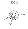
- the electric heater 31 is formed by covering a resistance-heating wire 31 A with an electrically insulating tube 31B.
- the resistance-heating wire 31A may suitably be made of a nichrome wire or a noble metal non-magnetic heating element such as platinum.
- the electrically insulating tube 31B may be a tube made by knitting fibrous alumina fibers, or connecting a plurality of quartz or alumina tubes.
- the resistance-heating wire 31 A is prepared by covering a nichrome wire having a diameter of from 2.0 to 2.6 mm with the tube 31B made by knitting alumina fibers, into an outside diameter of 3.5 mm.
- the resistance-heating wire 31 A being placed in the magnetic field produced by the magnetic field generating device 20 as described above, is subjected to application of a force resulting from the interaction with the magnetic field caused by the current for heating, leading to contact between resistance wires, for example. Therefore, the resistance-heating wire 31 A should preferably be electrically insulated with the insulating tube 31B.
- the heater 31 is wound on the inner cylinder 32 into a single-layer winding, in a dual-wire structure in which the wire is connected at an end, i.e., in a U shape. Therefore, the directions of the current flowing through the upper and lower resistance-heating wires 31A adjacent to each other in the axial direction are counter to each other. As a result, the magnetic field generated by the current flowing through the resistance-heating wires 31 A set off each other and are cancelled.
- the heater 31 is made by merely winding a single wire, the magnetic field from the magnetic field generating device 20, when current flows through the resistance-heating wire 31 A, applies a force onto the resistance-heating wire 31 A, resulting in a shift or vibration of the heater 31, as stated above.
- the heating current should preferably be a direct current (DC).
- a control device for controlling the temperature is usually provided for the heating device 30 to control the energizing of the heater 31.
- the heat treatment temperature is within a range of from about 150 °C. to 500 °C.
- the temperature should be specifically within a range of from about 500 °C. to 800 °C.
- the cooling rate should preferably be greater than or equal to 5 °C./minute, or particularly, within a range of from 15 °C./minute to 200 °C./minute.
- the inner peripheral surface temperature of the air-core coil 20A does not exceed 50°C., even in the region in which the air-core coil 20A and the heating device 30 are close to each other.
- No heat insulating material should preferably be provided around the heater 31.
- an alumina sheet 40 (FIG. 6) serving as a sheet-shaped electric insulator should preferably be arranged between the water-cooled jacket 33 and the heater 31.
- the alumina sheet 40 may have a thickness within a range of from about 1 to 3 mm.
- the electric insulator in the gap between the heater 31 and the water-cooled jacket 33 should preferably have a thickness of less than or equal to 4 mm.
- the heater 31 may be wound and positioned on the inner peripheral surface of the alumina sheet 40 without providing the inner cylinder 2.
- a heat reflection plate HR in the vacuum vessel 2, near the heating position where the objects of treatment held by the boats 3A are positioned, for collecting the heat from the heating device 30 onto the objects of treatment.
- a plurality of heat reflecting plates HRa are fixedly arranged on the closed end member 2B side of the vacuum vessel 2, and a plurality of heat reflecting plates HRb are arranged adjacent to the boats 3A which compose the holding device 3.
- the heat reflecting plates HRb are secured to the boat supporting unit 3B.
- the heat reflecting plates HRa and HRb are disks having generally the same diameter as the inside diameter of the vacuum vessel 2. About 0 to 10 such heat reflecting plates can be provided perpendicularly to the longitudinal axis line of the vacuum vessel at intervals of 10 to 50 mm along the longitudinal axis line direction. Stainless steel sheet having a thickness of 1.0 to 20 mm is applicable as a material of the plate.
- the aforementioned heat treatment apparatus 1 further comprises a magnetic field measuring controller, a control unit for the vacuum pump for evacuating the vacuum vessel 2, and a mechanism for controlling the operating sequence of the overall apparatus.
- a magnetic field measuring controller for the control unit for the vacuum pump for evacuating the vacuum vessel 2
- a mechanism for controlling the operating sequence of the overall apparatus may be ones well known by those skilled in the art. Detailed description thereof is therefore omitted here.
- the solenoid type magnet serving as the magnetic field generating device 20 may be a direct current (DC) normal conducting type electromagnet, but a direct current (DC) superconducting magnet is preferably applicable. In some cases, it is possible to use a permanent magnet.
- DC direct current
- DC direct current
- the solenoid type magnet i.e., the air-core coil 20A which composes the magnetic field generating device 20 has been described as being one in number, in the above-mentioned embodiment, it can be divided into a plurality of sections which are connected in series.
- the magnetic field generating device 20 comprises a DC superconducting electromagnet
- Such cooling controls of the two cooling devices require a very highly accuracy, and this is not practical. Therefore, the magnetic field generating device 20 should preferably be made of a single air-core coil 20A particularly when using a DC superconducting electromagnet.
- the heating device 30 has been explained in the above mentioned embodiment as being arranged outside the vacuum vessel 2, but as required, it may be installed in the vacuum vessel 2.
- the vacuum vessel 2 is attached to the lower structure 5 by using the attachments 51 and 52 as described above.
- At least the treatment chamber 50 in which the vacuum vessel opening and the conveying device 10 are arranged should preferably be a clean (dust-free) chamber.
- the treatment chamber i.e., the clean chamber 50 has generally a box shape, and is installed on a side of the vacuum vessel 2, the heating device 30, the magnetic field generating device 20 and the like. Therefore, the vessel attachment section 2B of the vacuum vessel 2 projects sideways into the clean chamber 50, and the vacuum vessel opening opens into the clean chamber 50.
- an open end member 2C of the vacuum vessel 2, the holder supporting unit 3B, and the conveying device 10 serving as a moving device are arranged in the clean chamber 50.
- handling means i.e., a handling robot 60 is installed.
- the handling robot 60 takes out the objects of treatment one by one in cooperation with a cassette elevator 61, and transfers the same to the boats 3A supported by the boat supporting unit 3B. Since the handling robot 60 and the cassette elevator 61 operating as described above are well known by those skilled in the art, a detailed description thereof is omitted here.
- handling robot 60 and the cassette elevator 61 can be installed in the clean chamber 50, they may also be installed in an intermediate chamber arranged adjacent to the clean chamber 50 via a opening capable of being sealed.
- the conveying device 10 is driven to horizontally move the boat supporting unit 3B and the boats 3A to charge the same into the vacuum vessel 2 from a side.
- the opening of the vacuum vessel 2 is closed by the closed cover 14 disposed on the conveying device 10.
- the interior of the vacuum vessel 2 is evacuated to reduce the pressure therein, and the interior of the vacuum vessel 2 is filled with a non-oxidizing atmosphere.
- the power source 20B of the magnetic field generating device 20 is turned on, and the power source of the heating device 30 is also turned on. A heat treatment is thus applied to the objects of treatment S supported by the boats 3A.
- the clean chamber 50 is in a hermetically closed state and in vacuum, while the opening of the vacuum vessel 2 is closed. As required, a prescribed atmosphere in the chamber is set.
- the interior of the clean chamber 50 is set to contain a non-oxidizing atmosphere of such as nitrogen or argon. Therefore, the interior of the clean chamber 50, after evacuation to below 1 Pa, is filled with nitrogen gas, in this embodiment, to achieve a nitrogen gas atmosphere at room temperature with a pressure of 1 atm (0.1 MPa). Alternatively, the interior of the clean chamber 50 may be left in vacuum state.
- a desired gas, a desired chamber temperature, a desired pressure and the like may be selected as required.
- the vacuum state in the vacuum vessel 2 is released by introducing nitrogen gas into the vacuum vessel 2 via a valve (not shown), and the boat supporting unit 3B and the boats 3A are moved sideways from the side opening of the vacuum vessel by driving the conveying device 10.
- the interior of the clean chamber 50 is kept in a non-oxidizing atmosphere state at the room temperature, thus allowing the heat-treated objects of treatment to be rapidly cooled without suffering from deterioration.
- the treated objects S supported by the boats 3A are transferred to a prescribed position by means of the handling robot 60, and the objects of treatment to be treated next which are housed in the cassette are transferred to the boats 3A.
- a heat treatment apparatus comprising a holding device which holds an object of treatment, a heat treatment vessel which houses the object of treatment held by the holding device, a conveying device which conveys the holding device together with the object of treatment into the heat treatment vessel, a heating device which heats the object of treatment, and a magnetic field generating device which impresses a magnetic field onto the object of treatment; wherein the direction of the magnetic field generated by the magnetic field generating device in a region in which the object of treatment is heat-treated and the conveying direction of the conveying device in which the object of treatment is conveyed into the heat treatment vessel are in parallel with each other, and are in parallel with the horizontal direction of the entire heat treatment apparatus; and wherein the object of treatment is heat-treated with the main surface thereof arranged in parallel with the direction of the magnetic field generated by the magnetic field generating device in the heat treatment region.
- the apparatus Since the apparatus has such a configuration, it is possible to simplify the configuration of the magnetic field generating device by using a compact solenoid type magnet (air-core coil) as the magnetic field generating device, thereby permitting saving of the weight and height of the apparatus, reducing the installation area to the same order as the conventional one, achieving an apparatus installable in a usual clean room, and treating a large quantity of large-sized objects of treatment as compared with the conventional art.
- a compact solenoid type magnet air-core coil
Landscapes
- Engineering & Computer Science (AREA)
- Mechanical Engineering (AREA)
- Manufacturing & Machinery (AREA)
- General Engineering & Computer Science (AREA)
- Power Engineering (AREA)
- Physics & Mathematics (AREA)
- Microelectronics & Electronic Packaging (AREA)
- Computer Hardware Design (AREA)
- General Physics & Mathematics (AREA)
- Chemical & Material Sciences (AREA)
- Condensed Matter Physics & Semiconductors (AREA)
- Thermal Sciences (AREA)
- Organic Chemistry (AREA)
- Metallurgy (AREA)
- Crystallography & Structural Chemistry (AREA)
- Materials Engineering (AREA)
- Furnace Details (AREA)
- Heat Treatment Of Articles (AREA)
- Muffle Furnaces And Rotary Kilns (AREA)
- Hall/Mr Elements (AREA)
Applications Claiming Priority (3)
| Application Number | Priority Date | Filing Date | Title |
|---|---|---|---|
| JP2003032933 | 2003-02-10 | ||
| JP2003032933A JP2004263206A (ja) | 2003-02-10 | 2003-02-10 | 熱処理装置 |
| PCT/JP2004/001241 WO2004070747A1 (ja) | 2003-02-10 | 2004-02-06 | 熱処理装置 |
Publications (3)
| Publication Number | Publication Date |
|---|---|
| EP1594145A1 true EP1594145A1 (de) | 2005-11-09 |
| EP1594145A4 EP1594145A4 (de) | 2010-09-01 |
| EP1594145B1 EP1594145B1 (de) | 2016-07-27 |
Family
ID=32844357
Family Applications (1)
| Application Number | Title | Priority Date | Filing Date |
|---|---|---|---|
| EP04708855.4A Expired - Lifetime EP1594145B1 (de) | 2003-02-10 | 2004-02-06 | Wärmebehandlungssystem |
Country Status (6)
| Country | Link |
|---|---|
| US (1) | US7179416B2 (de) |
| EP (1) | EP1594145B1 (de) |
| JP (1) | JP2004263206A (de) |
| KR (1) | KR101092025B1 (de) |
| CN (1) | CN100375208C (de) |
| WO (1) | WO2004070747A1 (de) |
Cited By (3)
| Publication number | Priority date | Publication date | Assignee | Title |
|---|---|---|---|---|
| DE102006058952A1 (de) * | 2006-12-14 | 2008-06-19 | Ecb Automation Gmbh | Reinraum-Manipulationssystem für Halbleiterscheiben |
| EP1975950A1 (de) * | 2006-01-13 | 2008-10-01 | International Superconductivity Technology Center | Wärmebehandlungsvorrichtung für supraleitenden oxiddraht |
| EP3276644A4 (de) * | 2015-03-23 | 2018-08-15 | Kabushiki Kaisha Toshiba | Dauermagnet, motor und generator |
Families Citing this family (30)
| Publication number | Priority date | Publication date | Assignee | Title |
|---|---|---|---|---|
| NO317391B1 (no) * | 2003-01-24 | 2004-10-18 | Sintef Energiforskning As | Anordning og fremgangsmate for induksjonsoppvarming av emner av elektrisk ledende og umagnetisk materiale |
| US20060226940A1 (en) * | 2005-04-07 | 2006-10-12 | Hitachi Global Storage Technologies | Method and apparatus for setting a sensor AFM with a superconducting magnet |
| JP2006296819A (ja) * | 2005-04-22 | 2006-11-02 | Etou Denki Kk | 注射針装置の針管分離方法、及び注射針装置の針管分離装置 |
| EP2605613A3 (de) * | 2008-04-11 | 2014-07-23 | The Timken Company | Induktionsheizung mit Magneten zur Härtung von Zahnradzähnen und ähnlichen Komponenten |
| EP2307581A1 (de) * | 2008-06-30 | 2011-04-13 | Eaton Corporation | Kontinuierliches produktionssystem zur magnetischen verarbeitung von metallen und legierungen zur massschneiderung von werkstoffen der nächsten generation |
| JP5324863B2 (ja) * | 2008-08-22 | 2013-10-23 | 株式会社神戸製鋼所 | 真空炉及びこの真空炉を用いた磁場中加熱処理装置 |
| US8993942B2 (en) | 2010-10-11 | 2015-03-31 | The Timken Company | Apparatus for induction hardening |
| JP4776044B1 (ja) * | 2010-11-16 | 2011-09-21 | ジャパン・フィールド株式会社 | 被洗浄物の洗浄装置 |
| JP5868619B2 (ja) * | 2011-06-21 | 2016-02-24 | ニチアス株式会社 | 熱処理炉及び熱処理装置 |
| CN102254675B (zh) * | 2011-07-14 | 2013-09-11 | 江西大有科技有限公司 | 软磁合金铁芯热处理工艺 |
| CN102392108A (zh) * | 2011-11-10 | 2012-03-28 | 朱巧明 | 一种导磁铁芯的加磁退火炉 |
| EP2827347A4 (de) * | 2012-03-12 | 2016-01-20 | Nitto Denko Corp | Seltenerd-permanentmagnet und verfahren zur herstellung des seltenerd-permanentmagneten |
| JP6134173B2 (ja) * | 2013-03-21 | 2017-05-24 | 東京エレクトロン株式会社 | 磁気アニール装置 |
| JP6134174B2 (ja) * | 2013-03-21 | 2017-05-24 | 東京エレクトロン株式会社 | 磁気アニール装置 |
| JP6134172B2 (ja) * | 2013-03-21 | 2017-05-24 | 東京エレクトロン株式会社 | 磁気アニール装置 |
| US10297481B2 (en) * | 2013-03-21 | 2019-05-21 | Tokyo Electron Limited | Magnetic annealing apparatus |
| US9508914B2 (en) * | 2013-03-21 | 2016-11-29 | Tokyo Electron Limited | Magnetic annealing apparatus |
| JP6333126B2 (ja) | 2014-08-29 | 2018-05-30 | 東京エレクトロン株式会社 | 磁気アニール装置及び磁気アニール方法 |
| JP6333128B2 (ja) | 2014-09-03 | 2018-05-30 | 東京エレクトロン株式会社 | 磁気アニール装置 |
| US10100409B2 (en) * | 2015-02-11 | 2018-10-16 | United Technologies Corporation | Isothermal warm wall CVD reactor |
| CN104900802B (zh) | 2015-04-27 | 2018-02-13 | 江苏多维科技有限公司 | 用于自旋电子器件钉扎层的快速热处理方法和装置 |
| CN105161290B (zh) * | 2015-07-10 | 2017-05-03 | 中国船舶重工集团公司第七一〇研究所 | 一种用于巨磁阻抗磁传感器磁芯的退火装置 |
| JP6412839B2 (ja) * | 2015-08-28 | 2018-10-24 | 東京エレクトロン株式会社 | 磁化処理装置及び磁化処理方法 |
| JP6532360B2 (ja) | 2015-09-16 | 2019-06-19 | 東京エレクトロン株式会社 | 半導体装置の製造方法 |
| CN105371650A (zh) * | 2015-12-17 | 2016-03-02 | 吉首大学 | 一种连续生产的真空炉 |
| JP7154986B2 (ja) * | 2018-12-11 | 2022-10-18 | 平田機工株式会社 | 基板搬送装置及び基板搬送システム |
| CN111739722A (zh) * | 2020-05-11 | 2020-10-02 | 湖北华磁电子科技有限公司 | 一种软磁铁氧体磁芯烧结支撑装置 |
| KR102489719B1 (ko) * | 2020-10-05 | 2023-01-17 | 국방과학연구소 | 진공 열처리 장치 및 이의 제조방법 |
| CN112921167A (zh) * | 2021-01-25 | 2021-06-08 | 西安聚能超导磁体科技有限公司 | 一种强磁场热处理装备 |
| CN115927824B (zh) * | 2022-12-28 | 2024-07-09 | 二重(德阳)重型装备有限公司 | 控制u形件热处理变形的方法 |
Citations (3)
| Publication number | Priority date | Publication date | Assignee | Title |
|---|---|---|---|---|
| US4147432A (en) * | 1975-11-26 | 1979-04-03 | Nippondenso Co., Ltd. | Apparatus for thermal diffusion by high frequency induction heating of semiconductor substrates |
| US6181535B1 (en) * | 1998-03-06 | 2001-01-30 | Tdk Corporation | Magnetoresistance effect head obtained using a pulse magnetic field process |
| US20020151154A1 (en) * | 2001-03-16 | 2002-10-17 | Semiconductor Energy Laboratory Co. Ltd. | Heat treatment apparatus and heat treatment method |
Family Cites Families (9)
| Publication number | Priority date | Publication date | Assignee | Title |
|---|---|---|---|---|
| CN2105276U (zh) | 1991-11-15 | 1992-05-27 | 张奕忠 | 多用途按摩套装置 |
| JP2000182956A (ja) * | 1998-12-15 | 2000-06-30 | Sony Corp | 半導体薄膜の結晶化方法及びレーザ結晶化装置 |
| JP2001135543A (ja) * | 1999-08-26 | 2001-05-18 | Nikko Consulting & Engineering Co Ltd | 熱処理装置 |
| US6303908B1 (en) * | 1999-08-26 | 2001-10-16 | Nichiyo Engineering Corporation | Heat treatment apparatus |
| JP4357786B2 (ja) * | 2001-03-16 | 2009-11-04 | 株式会社半導体エネルギー研究所 | 熱処理装置及び熱処理方法 |
| JP4423586B2 (ja) * | 2001-04-17 | 2010-03-03 | 日立金属株式会社 | 磁場中熱処理炉 |
| DE10216865A1 (de) | 2001-04-17 | 2002-12-12 | Hitachi Metals Ltd | Wärmebehandlungsofen mit Magnetfeld sowie Wärmebehandlungsverfahren unter Verwendung desselben |
| JP4181761B2 (ja) * | 2001-06-21 | 2008-11-19 | ジュン キム ヒョン | 熱感受性非導電性基板上の半導体フィルムを熱処理するための方法および装置 |
| AU2003211416A1 (en) * | 2002-02-25 | 2003-09-09 | Futek Furnace Inc. | Device and method for heat treatment |
-
2003
- 2003-02-10 JP JP2003032933A patent/JP2004263206A/ja active Pending
-
2004
- 2004-02-06 KR KR1020057014661A patent/KR101092025B1/ko active IP Right Grant
- 2004-02-06 CN CNB2004800038569A patent/CN100375208C/zh not_active Expired - Lifetime
- 2004-02-06 EP EP04708855.4A patent/EP1594145B1/de not_active Expired - Lifetime
- 2004-02-06 WO PCT/JP2004/001241 patent/WO2004070747A1/ja active Application Filing
-
2005
- 2005-08-05 US US11/198,463 patent/US7179416B2/en not_active Expired - Lifetime
Patent Citations (3)
| Publication number | Priority date | Publication date | Assignee | Title |
|---|---|---|---|---|
| US4147432A (en) * | 1975-11-26 | 1979-04-03 | Nippondenso Co., Ltd. | Apparatus for thermal diffusion by high frequency induction heating of semiconductor substrates |
| US6181535B1 (en) * | 1998-03-06 | 2001-01-30 | Tdk Corporation | Magnetoresistance effect head obtained using a pulse magnetic field process |
| US20020151154A1 (en) * | 2001-03-16 | 2002-10-17 | Semiconductor Energy Laboratory Co. Ltd. | Heat treatment apparatus and heat treatment method |
Non-Patent Citations (1)
| Title |
|---|
| See also references of WO2004070747A1 * |
Cited By (5)
| Publication number | Priority date | Publication date | Assignee | Title |
|---|---|---|---|---|
| EP1975950A1 (de) * | 2006-01-13 | 2008-10-01 | International Superconductivity Technology Center | Wärmebehandlungsvorrichtung für supraleitenden oxiddraht |
| EP1975950A4 (de) * | 2006-01-13 | 2012-04-11 | Int Superconductivity Tech | Wärmebehandlungsvorrichtung für supraleitenden oxiddraht |
| DE102006058952A1 (de) * | 2006-12-14 | 2008-06-19 | Ecb Automation Gmbh | Reinraum-Manipulationssystem für Halbleiterscheiben |
| EP3276644A4 (de) * | 2015-03-23 | 2018-08-15 | Kabushiki Kaisha Toshiba | Dauermagnet, motor und generator |
| US10892091B2 (en) | 2015-03-23 | 2021-01-12 | Kabushiki Kaisha Toshiba | Permanent magnet, motor, and generator |
Also Published As
| Publication number | Publication date |
|---|---|
| KR20050095784A (ko) | 2005-09-30 |
| US7179416B2 (en) | 2007-02-20 |
| WO2004070747A1 (ja) | 2004-08-19 |
| KR101092025B1 (ko) | 2011-12-12 |
| EP1594145B1 (de) | 2016-07-27 |
| CN100375208C (zh) | 2008-03-12 |
| JP2004263206A (ja) | 2004-09-24 |
| EP1594145A4 (de) | 2010-09-01 |
| US20060022387A1 (en) | 2006-02-02 |
| CN1748268A (zh) | 2006-03-15 |
Similar Documents
| Publication | Publication Date | Title |
|---|---|---|
| EP1594145B1 (de) | Wärmebehandlungssystem | |
| EP1487006A1 (de) | Einrichtung und verfahren zur wärmebehandlung | |
| US8837924B2 (en) | Vacuum heating/cooling apparatus and manufacturing method of magnetoresistance element | |
| KR101102678B1 (ko) | 열 처리 장치 | |
| KR101005384B1 (ko) | 열처리 장치 | |
| TW526672B (en) | Heater for heating a substrate in a processing gas within a processing reactor, multi-zone heater for heating a substrate in a processing gas within a processing reactor, and method of measuring clamping of a substrate to an electrostatic chuck | |
| TW399396B (en) | Inductively coupled RF plasma reactor having an overhead solenoidal antenna and modular confinement magnet liners | |
| EP0386447B1 (de) | Einrichtung und Verfahren zur Behandlung von Halbleiterscheiben | |
| JP5029382B2 (ja) | 処理装置及び処理方法 | |
| JP4924395B2 (ja) | 処理装置及び処理方法 | |
| US6496648B1 (en) | Apparatus and method for rapid thermal processing | |
| US6303908B1 (en) | Heat treatment apparatus | |
| JP2001210631A (ja) | 熱処理装置 | |
| KR20040010620A (ko) | 처리 장치 및 처리 방법 | |
| JP2009518617A (ja) | 磁気焼鈍装置の熱交換システム及び方法 | |
| JP2015067878A (ja) | 熱処理装置及び熱処理方法 | |
| JP2000277521A (ja) | 半導体ウェーハの高温高圧処理方法及び装置 | |
| JP2005032933A (ja) | 基板処理装置 | |
| JP2001135543A (ja) | 熱処理装置 | |
| JP2003133319A (ja) | 高圧アニール装置 | |
| KR20110075661A (ko) | 토카막의 진공용기 코팅 유로 가열구조 | |
| JP2005116752A (ja) | 基板処理装置 | |
| JP2006045635A (ja) | 基板処理装置 |
Legal Events
| Date | Code | Title | Description |
|---|---|---|---|
| PUAI | Public reference made under article 153(3) epc to a published international application that has entered the european phase |
Free format text: ORIGINAL CODE: 0009012 |
|
| 17P | Request for examination filed |
Effective date: 20050810 |
|
| AK | Designated contracting states |
Kind code of ref document: A1 Designated state(s): AT BE BG CH CY CZ DE DK EE ES FI FR GB GR HU IE IT LI LU MC NL PT RO SE SI SK TR |
|
| AX | Request for extension of the european patent |
Extension state: AL LT LV MK |
|
| DAX | Request for extension of the european patent (deleted) | ||
| RBV | Designated contracting states (corrected) |
Designated state(s): DE FR GB IE |
|
| RAP1 | Party data changed (applicant data changed or rights of an application transferred) |
Owner name: FFK, INC. |
|
| RAP1 | Party data changed (applicant data changed or rights of an application transferred) |
Owner name: FUTEK FURNACE INC. |
|
| A4 | Supplementary search report drawn up and despatched |
Effective date: 20100729 |
|
| RIC1 | Information provided on ipc code assigned before grant |
Ipc: F27B 14/16 20060101ALI20100723BHEP Ipc: H01F 41/18 20060101AFI20040826BHEP Ipc: H01F 41/22 20060101ALI20100723BHEP Ipc: C21D 1/04 20060101ALI20100723BHEP Ipc: F27D 3/12 20060101ALI20100723BHEP Ipc: H01L 43/08 20060101ALI20100723BHEP Ipc: H01L 43/12 20060101ALI20100723BHEP Ipc: G11B 5/39 20060101ALI20100723BHEP Ipc: H01L 21/00 20060101ALI20100723BHEP |
|
| 17Q | First examination report despatched |
Effective date: 20101217 |
|
| RAP1 | Party data changed (applicant data changed or rights of an application transferred) |
Owner name: FUTEK HOLDINGS, LLC |
|
| RAP1 | Party data changed (applicant data changed or rights of an application transferred) |
Owner name: TOKYO ELECTRON LIMITED |
|
| GRAP | Despatch of communication of intention to grant a patent |
Free format text: ORIGINAL CODE: EPIDOSNIGR1 |
|
| INTG | Intention to grant announced |
Effective date: 20160218 |
|
| GRAS | Grant fee paid |
Free format text: ORIGINAL CODE: EPIDOSNIGR3 |
|
| GRAA | (expected) grant |
Free format text: ORIGINAL CODE: 0009210 |
|
| AK | Designated contracting states |
Kind code of ref document: B1 Designated state(s): DE FR GB IE |
|
| REG | Reference to a national code |
Ref country code: GB Ref legal event code: FG4D |
|
| REG | Reference to a national code |
Ref country code: IE Ref legal event code: FG4D |
|
| REG | Reference to a national code |
Ref country code: DE Ref legal event code: R096 Ref document number: 602004049656 Country of ref document: DE |
|
| REG | Reference to a national code |
Ref country code: FR Ref legal event code: PLFP Year of fee payment: 14 |
|
| REG | Reference to a national code |
Ref country code: DE Ref legal event code: R097 Ref document number: 602004049656 Country of ref document: DE |
|
| PLBE | No opposition filed within time limit |
Free format text: ORIGINAL CODE: 0009261 |
|
| STAA | Information on the status of an ep patent application or granted ep patent |
Free format text: STATUS: NO OPPOSITION FILED WITHIN TIME LIMIT |
|
| 26N | No opposition filed |
Effective date: 20170502 |
|
| GBPC | Gb: european patent ceased through non-payment of renewal fee |
Effective date: 20170206 |
|
| REG | Reference to a national code |
Ref country code: FR Ref legal event code: PLFP Year of fee payment: 15 |
|
| PG25 | Lapsed in a contracting state [announced via postgrant information from national office to epo] |
Ref country code: GB Free format text: LAPSE BECAUSE OF NON-PAYMENT OF DUE FEES Effective date: 20170206 |
|
| PGFP | Annual fee paid to national office [announced via postgrant information from national office to epo] |
Ref country code: IE Payment date: 20230110 Year of fee payment: 20 Ref country code: FR Payment date: 20230110 Year of fee payment: 20 |
|
| PGFP | Annual fee paid to national office [announced via postgrant information from national office to epo] |
Ref country code: DE Payment date: 20221229 Year of fee payment: 20 |
|
| REG | Reference to a national code |
Ref country code: DE Ref legal event code: R071 Ref document number: 602004049656 Country of ref document: DE |
|
| REG | Reference to a national code |
Ref country code: IE Ref legal event code: MK9A |
|
| PG25 | Lapsed in a contracting state [announced via postgrant information from national office to epo] |
Ref country code: IE Free format text: LAPSE BECAUSE OF EXPIRATION OF PROTECTION Effective date: 20240206 |
|
| PG25 | Lapsed in a contracting state [announced via postgrant information from national office to epo] |
Ref country code: IE Free format text: LAPSE BECAUSE OF EXPIRATION OF PROTECTION Effective date: 20240206 |