EP1593852B1 - Umwälzpumpe und Verfahren zur Flüssigkeitsschmierung eines sphärischen Lagers in einem Elektromotor - Google Patents
Umwälzpumpe und Verfahren zur Flüssigkeitsschmierung eines sphärischen Lagers in einem Elektromotor Download PDFInfo
- Publication number
- EP1593852B1 EP1593852B1 EP05008872.3A EP05008872A EP1593852B1 EP 1593852 B1 EP1593852 B1 EP 1593852B1 EP 05008872 A EP05008872 A EP 05008872A EP 1593852 B1 EP1593852 B1 EP 1593852B1
- Authority
- EP
- European Patent Office
- Prior art keywords
- circulating pump
- pump according
- rotor
- lubrication
- region
- Prior art date
- Legal status (The legal status is an assumption and is not a legal conclusion. Google has not performed a legal analysis and makes no representation as to the accuracy of the status listed.)
- Expired - Lifetime
Links
Images


Classifications
-
- F—MECHANICAL ENGINEERING; LIGHTING; HEATING; WEAPONS; BLASTING
- F04—POSITIVE - DISPLACEMENT MACHINES FOR LIQUIDS; PUMPS FOR LIQUIDS OR ELASTIC FLUIDS
- F04D—NON-POSITIVE-DISPLACEMENT PUMPS
- F04D29/00—Details, component parts, or accessories
- F04D29/04—Shafts or bearings, or assemblies thereof
- F04D29/046—Bearings
- F04D29/0467—Spherical bearings
-
- F—MECHANICAL ENGINEERING; LIGHTING; HEATING; WEAPONS; BLASTING
- F04—POSITIVE - DISPLACEMENT MACHINES FOR LIQUIDS; PUMPS FOR LIQUIDS OR ELASTIC FLUIDS
- F04D—NON-POSITIVE-DISPLACEMENT PUMPS
- F04D13/00—Pumping installations or systems
- F04D13/02—Units comprising pumps and their driving means
- F04D13/06—Units comprising pumps and their driving means the pump being electrically driven
- F04D13/0606—Canned motor pumps
- F04D13/0633—Details of the bearings
-
- F—MECHANICAL ENGINEERING; LIGHTING; HEATING; WEAPONS; BLASTING
- F04—POSITIVE - DISPLACEMENT MACHINES FOR LIQUIDS; PUMPS FOR LIQUIDS OR ELASTIC FLUIDS
- F04D—NON-POSITIVE-DISPLACEMENT PUMPS
- F04D29/00—Details, component parts, or accessories
- F04D29/06—Lubrication
- F04D29/061—Lubrication especially adapted for liquid pumps
-
- F—MECHANICAL ENGINEERING; LIGHTING; HEATING; WEAPONS; BLASTING
- F16—ENGINEERING ELEMENTS AND UNITS; GENERAL MEASURES FOR PRODUCING AND MAINTAINING EFFECTIVE FUNCTIONING OF MACHINES OR INSTALLATIONS; THERMAL INSULATION IN GENERAL
- F16C—SHAFTS; FLEXIBLE SHAFTS; ELEMENTS OR CRANKSHAFT MECHANISMS; ROTARY BODIES OTHER THAN GEARING ELEMENTS; BEARINGS
- F16C17/00—Sliding-contact bearings for exclusively rotary movement
- F16C17/04—Sliding-contact bearings for exclusively rotary movement for axial load only
- F16C17/08—Sliding-contact bearings for exclusively rotary movement for axial load only for supporting the end face of a shaft or other member, e.g. footstep bearings
-
- F—MECHANICAL ENGINEERING; LIGHTING; HEATING; WEAPONS; BLASTING
- F16—ENGINEERING ELEMENTS AND UNITS; GENERAL MEASURES FOR PRODUCING AND MAINTAINING EFFECTIVE FUNCTIONING OF MACHINES OR INSTALLATIONS; THERMAL INSULATION IN GENERAL
- F16C—SHAFTS; FLEXIBLE SHAFTS; ELEMENTS OR CRANKSHAFT MECHANISMS; ROTARY BODIES OTHER THAN GEARING ELEMENTS; BEARINGS
- F16C23/00—Bearings for exclusively rotary movement adjustable for aligning or positioning
- F16C23/02—Sliding-contact bearings
- F16C23/04—Sliding-contact bearings self-adjusting
- F16C23/043—Sliding-contact bearings self-adjusting with spherical surfaces, e.g. spherical plain bearings
-
- F—MECHANICAL ENGINEERING; LIGHTING; HEATING; WEAPONS; BLASTING
- F16—ENGINEERING ELEMENTS AND UNITS; GENERAL MEASURES FOR PRODUCING AND MAINTAINING EFFECTIVE FUNCTIONING OF MACHINES OR INSTALLATIONS; THERMAL INSULATION IN GENERAL
- F16C—SHAFTS; FLEXIBLE SHAFTS; ELEMENTS OR CRANKSHAFT MECHANISMS; ROTARY BODIES OTHER THAN GEARING ELEMENTS; BEARINGS
- F16C33/00—Parts of bearings; Special methods for making bearings or parts thereof
- F16C33/02—Parts of sliding-contact bearings
- F16C33/04—Brasses; Bushes; Linings
- F16C33/06—Sliding surface mainly made of metal
- F16C33/10—Construction relative to lubrication
- F16C33/1025—Construction relative to lubrication with liquid, e.g. oil, as lubricant
- F16C33/106—Details of distribution or circulation inside the bearings, e.g. details of the bearing surfaces to affect flow or pressure of the liquid
-
- F—MECHANICAL ENGINEERING; LIGHTING; HEATING; WEAPONS; BLASTING
- F16—ENGINEERING ELEMENTS AND UNITS; GENERAL MEASURES FOR PRODUCING AND MAINTAINING EFFECTIVE FUNCTIONING OF MACHINES OR INSTALLATIONS; THERMAL INSULATION IN GENERAL
- F16C—SHAFTS; FLEXIBLE SHAFTS; ELEMENTS OR CRANKSHAFT MECHANISMS; ROTARY BODIES OTHER THAN GEARING ELEMENTS; BEARINGS
- F16C2360/00—Engines or pumps
- F16C2360/44—Centrifugal pumps
-
- F—MECHANICAL ENGINEERING; LIGHTING; HEATING; WEAPONS; BLASTING
- F16—ENGINEERING ELEMENTS AND UNITS; GENERAL MEASURES FOR PRODUCING AND MAINTAINING EFFECTIVE FUNCTIONING OF MACHINES OR INSTALLATIONS; THERMAL INSULATION IN GENERAL
- F16C—SHAFTS; FLEXIBLE SHAFTS; ELEMENTS OR CRANKSHAFT MECHANISMS; ROTARY BODIES OTHER THAN GEARING ELEMENTS; BEARINGS
- F16C2380/00—Electrical apparatus
- F16C2380/26—Dynamo-electric machines or combinations therewith, e.g. electro-motors and generators
-
- F—MECHANICAL ENGINEERING; LIGHTING; HEATING; WEAPONS; BLASTING
- F16—ENGINEERING ELEMENTS AND UNITS; GENERAL MEASURES FOR PRODUCING AND MAINTAINING EFFECTIVE FUNCTIONING OF MACHINES OR INSTALLATIONS; THERMAL INSULATION IN GENERAL
- F16C—SHAFTS; FLEXIBLE SHAFTS; ELEMENTS OR CRANKSHAFT MECHANISMS; ROTARY BODIES OTHER THAN GEARING ELEMENTS; BEARINGS
- F16C25/00—Bearings for exclusively rotary movement adjustable for wear or play
- F16C25/02—Sliding-contact bearings
- F16C25/04—Sliding-contact bearings self-adjusting
- F16C25/045—Sliding-contact bearings self-adjusting with magnetic means to preload the bearing
Definitions
- the invention relates to a circulating pump with an electric motor, which comprises a rotor and a stator, wherein the rotor is mounted on a spherical bearing, which comprises a sliding body with a convex spherical surface and a bearing cup with concave spherical surface and which is liquid lubricated, and wherein Gap between the rotor and stator is formed.
- the invention further relates to a method for fluid lubrication of a spherical bearing with a sliding body and a bearing cup in an electric motor.
- centrifugal pump which has a suction side arranged spray nozzle, which directs a beam on a bearing shell of a paddle wheel, so that the bearing lubrication is maintained even with occasional inclusion of bubbles.
- Spherical bearings have the advantage that they are self-adjusting especially in connection with fluid lubrication, so that wear does not lead to increased bearing clearance.
- the invention has for its object to provide a circulating pump of the type mentioned with optimized bearing lubrication.
- a flow guide for performing lubrication fluid is separated by a lubrication between the slider and the bearing cup of the gap that connects to the lubrication region of the bearing cup away a room, said the lubrication region is sealed by a seal against the space and that the seal bears against the sliding body.
- the gap between the stator and the rotor is also referred to as the air gap, since the stator and rotor are electromagnetically coupled to one another via it. This electromagnetic coupling drives the rotational movement of the rotor. It is known from the prior art to guide lubrication fluid through this air gap. (The term air gap is retained, although lubrication fluid and especially water is in this gap.)
- the flow guide for the lubricating fluid avoids this gap.
- the bearing lubrication is independent of the air gap flow.
- lubrication fluid As lubrication fluid, a part of the liquid is used, which is transported by the circulation pump.
- This liquid can contain impurities.
- the impurities are not problematic per se.
- magnetic particles such as magnetic iron particles can settle there. An accumulation of such particles can lead to a blockage of the circulation pump.
- the inventive solution the passage of liquid through this critical gap region is avoided or at least greatly reduced. This avoids the problem of accumulation of magnetic particles.
- a flow guide is selected which just avoids the gap. Then no filter for (magnetic) particles must be provided.
- a flow guide, bypassing the gap between the stator and the rotor can be realized in a simple manner.
- the seal does not necessarily have to be perfect, i. H. It may be permissible for lubrication fluid to enter the room.
- this space which is in particular in connection with the gap between the stator and the rotor, can gradually fill with liquid or liquid can pass from this space into the lubrication area.
- the volume flow is negligible relative to the volume flow through the flow guide according to the invention, which bypasses the gap between the stator and the rotor.
- the proportion of liquid which flows through the air gap is therefore negligible with respect to the liquid fraction which flows through the lubrication region on account of the flow guidance according to the invention.
- the problem of accumulation of magnetic particles in the air gap is largely avoided.
- a seal is provided for sealing the lubrication area to the room.
- the volume flow rate of liquid and in particular lubrication fluid through the gap between the stator and rotor can be minimized thereby.
- the seal abuts against the slider. This provides a proper sealing effect and the volume flow rate of lubrication fluid through the seal can be minimized.
- the flow guide bypasses the gap between the stator and the rotor. It is preferably guided past the gap between the stator and the rotor.
- the flow guide is designed so that lubrication fluid can be supplied to the lubrication region via the rotor and can be discharged via the rotor. Lubricating fluid can then be coupled directly into the lubrication region and decoupled therefrom, without the air gap between stator and rotor having to be flowed through.
- the flow guide is formed on the rotor so as to be able to easily bypass the air gap.
- the flow guide comprises one or more flow channels, which are arranged in the rotor.
- lubrication fluid can be supplied directly to the lubrication area without the need for passage through the gap between the stator and the rotor.
- the flow guide comprises one or more supply channels for lubricating fluid in the lubrication region, which are formed in the rotor.
- the lubrication region is formed between the rotor designed in particular as a rotor shell and the sliding body. Through feed channels in the rotor lubrication fluid can be coupled directly into the lubrication area.
- the lubrication region is closed at the end between the sliding body and the bearing cup, ie at the end of a region between
- the lubrication region is closed to a holder for the slider out.
- the holder for the slider (and the slider) is non-rotatably relative to the stator. It can therefore be in fluid-effective connection with the gap between the stator and the rotor.
- the slider sits partially in the room. About this space rotation of the rotor relative to the stator is possible.
- a holder for the slider is at least partially disposed in the space. This ensures that the rotor, which is mounted in the spherical bearing, can rotate freely relative to the stator.
- the space is in fluid communication with the gap between the stator and the rotor. If the sealing of the lubrication area from the room is not perfect, lubrication liquid may enter the gap and gradually accumulate there. The water entering the room then does not have to be removed. At the same time, however, it is possible to ensure that the volume throughput of liquid through the gap between the stator and the rotor is minimal.
- the seal facing the slider on a peripheral edge. Over this peripheral edge, a seal can be achieved to the slider.
- the seal is integrally formed with the bearing cup.
- the bearing cup is then formed so that it bears in a sealing region on the slider with a peripheral edge, so that the passage of lubricating fluid between the bearing cup and the slider is minimized.
- At least one sealing element may be provided for sealing the lubrication space, wherein the sealing element is a separate sealing element from the bearing cup.
- a Teflon ring can be used.
- the sealing element is connected to the rotor outside the bearing cup. It is advantageous if the sealing element is seated on the bearing cup. It can be fixed there in a simple way. In principle, it would also be possible to fix the sealing element rotationally fixed to the slider. The rotor then rotates relative to the sealing element. However, it is advantageous if the sealing element is fixed to the rotor and rotates with this relative to the sliding body.
- sealing element in the form of a sealing ring (O-ring) is formed.
- the seal is arranged on this side of an equatorial plane of the slider, d. H. the cup does not extend beyond the equatorial plane and also does not extend beyond the seal.
- This has the advantage that the seal can adjust itself when the slider further "digs" in the bearing cup.
- Spherical bearings have the advantage that with appropriate design, the wear is also spherical, that is, that the spherical relationship between sliding body and bearing cup is maintained despite wear.This means for the overall system bearing cup sliding body an optimal seal and optimum bearing lubrication.
- the seal is disposed beyond an equatorial plane of the sliding body. This arrangement is made, for example, if a separate sealing element is provided.
- At least one flow channel can point laterally into the lubrication area.
- Lubricating fluid can then be coupled in, the lubrication area being lockable with respect to a free space (which is in connection with the gap between stator and rotor).
- a mouth opening of the at least one flow channel with which this in opens the lubrication region, aligned transversely to a rotational axis of the rotor. It can then achieve a flow through the lubrication area and thus an optimized fluid lubrication.
- the at least one flow channel is arranged in the bearing cup and / or on the bearing cup. Lubricating fluid can then be coupled through the rotor and in particular through the bearing cup into the lubrication region. If a separate sealing element is provided, then it is in principle sufficient if the at least one flow channel is produced via a corresponding surface formation of the bearing socket on a surface facing the sealing element.
- an orifice opening of the at least one flow channel, via which lubrication fluid can flow into the flow channel is in fluid-effective connection with a pressure region of the circulation pump. It is then ensured that lubrication fluid (as part of the liquid conveyed by the circulation pump) is transported through the flow channel and thus through the lubrication region.
- a lubrication opening is formed in the bearing cup.
- the lubrication opening is aligned with a rotational axis of the rotor. It is made of a central material-free area. If this central material-free area corresponding Having dimensions, then it can also ensure that the bearing wear is spherical.
- the lubrication opening is in fluid-effective connection with a suction region of the circulating pump.
- an automatic transport of lubrication fluid can be achieved by the flow guide, so as to ensure a transport of lubrication fluid through the lubrication area.
- a cover for the gap between the stator and the rotor is provided.
- the volume flow of liquid through the gap between the stator and rotor can be minimized.
- the cover can also be a direct remplisstechniksvorbelickung to avoid magnetic fields of the rotor outside of the air gap.
- the volume flow through the gap between the stator and the rotor can be kept low if a cover between an impeller and the electric motor is provided.
- the cover prevents fluid flow through the gap or at least reduces the volume fraction of liquid that can flow through the gap.
- a cover can be formed in a simple manner, for example in the form of a separating plate.
- the separating plate covers the gap at its end facing the pressure region towards an impeller space.
- the cover can be formed so that the mobility of the rotor relative to the stator is not hindered.
- a separation space is formed between the cover and the electric motor.
- the liquid flow through the (air) gap can be kept low while ensuring the rotatability of the rotor in a simple manner.
- the flow guide is expediently in fluid-effective connection with a pressure region of the circulation pump and in a fluid-effective connection with a suction region, wherein lubrication fluid can flow through the lubrication region via at least one flow channel.
- the connection to the pressure area and the suction area ensures fluid lubrication of the spherical bearing, regardless of the operating parameters of the electric motor.
- a bearing area of the spherical bearing between the electric motor and an impeller is preferably arranged. This arrangement refers to the direction of the axis of rotation.
- the bearing area is that spherical area in which the bearing cup slides on the slider.
- an opening may be provided between a space in which a holder for the slider is at least partially disposed and a separation space, the separation space being below an impeller space.
- the separation space is limited to the impeller space, for example by a cover.
- liquid can penetrate into this space in a friction pump to the cooling of Stator and / or rotor to improve.
- a cover In cooperation with a cover then a kind of closed circuit through the space, the air gap and a space between a cover and the rotor can be formed.
- the invention is further based on the object to provide a method for fluid lubrication of a spherical bearing with a slider and a bearing cup in an electric motor, which works in all operating parameters of the electric motor or all system pressures.
- the method according to the invention has the advantages already explained in connection with the circulating pump according to the invention.
- a flow path is or is released by a rotor of the electric motor and a flow path between the rotor and a stator is blocked.
- a bearing lubrication can be achieved bypassing the air gap.
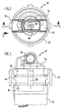
- FIGS. 1 to 3 An embodiment of a circulating pump according to the invention, which in the FIGS. 1 to 3 shown there and designated as a whole by 10, comprises a first housing 12 (motor housing), in which a designated as a whole by 14 electric motor is arranged.
- This electric motor 14 has a stator 16 which includes a plurality of coils (not shown in the drawing). Via a drive circuit 18, these coils can be controlled. For example, they are commutated electronically.
- the stator 16 is protected against the action of liquid by a separating calotte 20. This separation cap 20 surrounds the stator 16 and seals it in the housing 12.
- the separating calotte 20 has a region 22 with a spherical concave surface.
- a ball portion 24 is defined, in which a rotor 26 is arranged rotatably about a rotation axis 28.
- the axis of rotation 28 passes through a ball center of the (imaginary) ball, which defines the ball portion 24.
- the rotor 26 has, for example, a plurality of permanent magnets 30. It is the sphere 22 of the separation cap 20 facing the stator 16 spherically convex. The permanent magnets 30 are protected by a jacket 32 against the influence of liquid. The separation cap 20 facing the sheath 32 is spherically convex. Between the rotor 26 and the stator 16, an air gap 33 is formed, which is bounded by the sheath 32 and the separation cap 20. This air gap 33 has a spherical shell-shaped formation in the region of the spherical surfaces of the separating cap 20 and the casing 32.
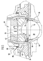
- a spherical bearing 34 For supporting the rotor 26 in the housing 12, a spherical bearing 34 is provided.
- This spherical bearing 34 comprises a holder 36 which is designed as a bearing column and which is stationary with respect to the housing 12.
- the holder 36 is formed as a metal column, wherein the corresponding metal parts are connected to the separation cap 20.
- the holder 36 may also be formed integrally with the separation cap 20.
- the holder 36 is made of a plastic material.
- the holder 36 holds a slider 38, which is formed in particular as a ball.
- This slider 38 is made of a hard material such as a ceramic material. It has a spherically convex surface 40 on which a bearing cup 42 of the rotor 26 slides.
- the bearing cup 42 of the rotor 26 has for this purpose a spherical concave surface 44, which is adapted to the spherical convex surface 40 of the slider 38. It is then formed a spherical storage area.
- the bearing cup 42 is made of coal, for example.
- the axis of rotation 28 of the rotor 26 passes through the ball center of the slider 38th
- a free space 46 is formed so that the rotor 26 is cup-shaped ("rotor shell") and on the slider 38, which in turn sits on the holder 36, can be placed.
- rotor 26 of the holder 36 is at least partially in this space 46.
- the slider 38 is then also partially in this space 46th
- the permanent magnets 30 are sealed by partitions 47.
- the walls 48 which form the holder 36 are in particular connected to the casing 32 and may be formed integrally therewith.
- the spherical bearing region of the spherical bearing 34 is seated relative to the axis of rotation 28 between the impeller 50 and the electric motor 14.
- the impeller 50 is disposed in an impeller space 52 of a second housing 54 (pump housing).
- the second housing 54 is seated on the first housing 12.
- About the second housing 54 can be the impeller chamber 52 supply liquid and remove it from this liquid.
- the second housing 54 has a first connection 56, via which liquid can be discharged from the impeller space 52.
- This first connection 56 stands in fluid-effective connection with a pressure region 58 of the second housing 54. Liquid present in the pressure region 58 is under overpressure with respect to a suction region 60.
- the housing 54 also has a second port 62, via which liquid can be supplied.
- the second port 62 is in fluid communication with the suction region 60 of the circulation pump 10.
- the suction region 60 and the pressure region 58 are defined by the arrangement and design of the impeller 50 in the impeller space 52. In the exemplary embodiment shown, the pressure region 58 surrounds the sides of the impeller 50 in an annular manner. The suction region 60 lies above the impeller 50.
- the second housing 54 is placed on the first housing 12.
- a seal 66 is provided, for example in the form of an O-ring. Via a flange 67, the two housings 12 and 54 can be connected to each other.
- the spherical bearing 34 is liquid-lubricated with the liquid to be circulated (conveying liquid).
- lubrication fluid is introduced into a lubrication area 68 (FIG. FIG. 4 ) is coupled into the region between the slider 38 and the bearing cup 42.
- the lubrication region 68 is sealed off from the free space 46.
- the free space 46 is in fluid-effective connection with the air gap 33.
- the bearing cup 42 has a plurality of lubrication grooves on the lubrication region 68, which improve lubricant lubrication.
- a sealing element 70 is provided for sealing.
- a sealing element which is designed in particular as a sealing ring, may for example be made of Teflon.
- the sealing element 70 faces the sliding body 38 facing a peripheral edge 74, with which it rests against the slider 38, so just to provide for the seal to the free space 46 out.
- the sealing element 70 sits on this side of an equatorial plane 76 of the slider 38, d. H. does not protrude beyond this equatorial plane 76. This has the advantage that the sealing element 70 can adjust itself when changing the relative position between the bearing cup 42 and the slider 38.
- the sealing element 70 prefferably be at a distance from the bearing socket 42, thereby defining the boundary between the clearance 46 and the lubrication region 68.
- a flow guide 80 provided in order to be able to supply the lubrication region 68 with lubricating fluid and to be able to carry out lubricating fluid.
- An exemplary embodiment of such a flow guide is based on the FIG. 5 explained.
- the flow guide 80 is formed on the rotor 26 so that the lubrication region 68 can bypass the air gap 33 to carry out lubrication fluid.
- the flow guide 80 has a plurality of flow channels 82. These include at least one feed channel 84, via which lubrication fluid is coupled into the lubrication region 68, and at least one discharge channel 86, via which lubrication fluid can be discharged from the lubrication region 68. This in turn allows lubrication fluid to pass through the lubrication area 68 to provide fluid lubrication to the spherical bearing 34.
- the at least one supply channel 84 has a (injection) orifice 88 which is in fluid communication with the pressure region 58 of the circulation pump 10. Liquid is then coupled into such a feed channel 84. This liquid forms lubrication fluid for the spherical bearing 34.
- the at least one supply channel 84 is formed in the bearing cup 42 and has a (decoupling) orifice 90 in the lubrication region 68.
- the orifice 90 is arranged laterally (with respect to the axis of rotation 28), ie, the at least one feed channel 84 opens laterally into the lubrication region 68.
- the feed channel 84 may comprise a transverse bore in the bearing socket 42 (relative to the axis of rotation 28) and / or it can be a Qu LucassEnglishung 92 at one Sealing element 70 facing surface of the bearing cup 42 may be provided.
- the transverse recess 92 may for example also be designed annular, so that the lubrication region 68 can be supplied with lubricating fluid over its entire circumference.
- a feed channel 84 may also have a plurality of such transverse bores or transverse recesses or be connected to a plurality of such transverse recesses.
- the bearing cup 42 has a central (with respect to the axis of rotation 28) lubrication opening 94. Lubrication fluid can be removed via this lubrication opening (which forms the discharge channel 86 or is part of this discharge channel 86).
- the lubrication opening 94 is in fluid-effective connection with the suction region 60 of the circulating pump 10.
- a cover 98 ( FIGS. 1 and 4 ) is provided between the impeller 50 and the rotor 26. This cover 98 is seated, for example, in the first housing 12. This cover 98 is designed in particular in the form of a separating plate. The cover 98 covers the air gap 33 up to the impeller space 52 and in particular to the pressure area 58 from. As a result, the flow rate of liquid through the air gap 33 is blocked or at least greatly reduced.
- the cover 98 is arranged so that the rotation of the rotor 26 and the impeller 50 is not hindered.
- the cover 98 is connected to the separation cap 20 of the stator 16 and partially engages over the rotor 26 so as to cover the gap 33.
- the lubrication region 68 is supplied with lubricating fluid by the rotor 26 so as to prevent the flow of the air gap 33 largely. It is allowed that liquid can accumulate in the air gap 33. However, the seal (via the sealing element 70) must be so tight that the volumetric flow of lubrication fluid through the lubrication region 68 is predominantly bypassing the air gap 33.
- the sealing element 70 is a separate with respect to the bearing cup 42 seal.
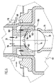
- seals of the lubrication region 68 with respect to the clearance 46 are integrally formed on a corresponding bearing cup 100 (FIG. FIG. 6 ) are formed.
- the bearing cup has for this purpose a spherical concave surface 102, which faces the slider 38.
- the slider 38 and the holder 36 are basically the same design as described above, so that the same reference numerals are used.
- the bearing cup At its end facing the free space 46, the bearing cup has a peripheral edge 103, with which it bears against the slider 38, just to ensure a seal of a lubrication 104 against the space 46 and thus against the air gap 33.
- the peripheral edge 103 is - in contrast to known from the prior art storage pans - not interrupted, just to provide a closure of the lubrication region 104 relative to the free space 46.
- a plurality of flow channels 106 are preferably provided, which are arranged distributed around an inner circumference of the bearing cup 100 about the axis of rotation 28.
- the flow channels 106 have respective respective mouth openings 108, with which they open directly into the lubrication area 104.
- the orifices 108 are preferably arranged in the vicinity of the seal 103 (the peripheral edge) of the flow region 104, so that the flow region 104 can be flowed through over a large area.
- the flow channels 106 are in turn connected to the pressure region 58 of the circulation pump 10, so that lubrication fluid from the pressure region 58 in the lubrication region 104 can be coupled.
- the flow channels 106 extend parallel to the axis of rotation 28 through the bearing cup 100 and then open via the mouth openings 108 in the lubrication region 104.
- an opening 110 is formed, which in turn with the one or more flow channels 106th connected is. The opening 110 opens into the pressure region 58 of the circulation pump.
- a central lubrication opening 114 is formed in the bearing cup 100, which opens via a channel 116 in the suction region 60 of the circulation pump.
- lubrication fluid can be transported through the lubrication region 104, bypassing the air gap 33.
- At least one opening 120 between the free space 46 and a separation space 122 is formed.
- the separation space 122 is disposed below the impeller space 52 facing the electric motor 14.
- the separation space 122 and the impeller space 52 are separated by the cover 98 (which is in particular a separating plate).
- the opening 120 opens into the separation chamber 122.
- Liquid can flow from the region 122 into the free space 46 through the opening 120. It can thereby form an approximately closed fluid circuit through the space 46, the gap 33 and the space 122. By means of the friction pump, liquid can be transported through the air gap 33 via this circuit so as to cool the rotor 26 and / or the stator 16. Since this cycle is approximately closed, the problem of accumulation of magnetic particles does not occur.
- the free space 46 and the area 122 is filled up with liquid, so that it is possible to form the closed circuit with cooling effect in the case of the friction pump.
Landscapes
- Engineering & Computer Science (AREA)
- General Engineering & Computer Science (AREA)
- Mechanical Engineering (AREA)
- Chemical & Material Sciences (AREA)
- Oil, Petroleum & Natural Gas (AREA)
- Structures Of Non-Positive Displacement Pumps (AREA)
Applications Claiming Priority (2)
| Application Number | Priority Date | Filing Date | Title |
|---|---|---|---|
| DE102004023790.5A DE102004023790B4 (de) | 2004-05-07 | 2004-05-07 | Umwälzpumpe und Verfahren zur Flüssigkeitsschmierung eines sphärischen Lagers in einem Elektromotor |
| DE102004023790 | 2004-05-07 |
Publications (3)
| Publication Number | Publication Date |
|---|---|
| EP1593852A2 EP1593852A2 (de) | 2005-11-09 |
| EP1593852A3 EP1593852A3 (de) | 2012-10-31 |
| EP1593852B1 true EP1593852B1 (de) | 2016-11-16 |
Family
ID=34935604
Family Applications (1)
| Application Number | Title | Priority Date | Filing Date |
|---|---|---|---|
| EP05008872.3A Expired - Lifetime EP1593852B1 (de) | 2004-05-07 | 2005-04-22 | Umwälzpumpe und Verfahren zur Flüssigkeitsschmierung eines sphärischen Lagers in einem Elektromotor |
Country Status (4)
| Country | Link |
|---|---|
| US (1) | US7854599B2 (enExample) |
| EP (1) | EP1593852B1 (enExample) |
| JP (1) | JP4813086B2 (enExample) |
| DE (1) | DE102004023790B4 (enExample) |
Families Citing this family (6)
| Publication number | Priority date | Publication date | Assignee | Title |
|---|---|---|---|---|
| DE102008023574A1 (de) | 2008-05-05 | 2009-11-12 | Laing, Oliver | Umwälzpumpe |
| DE102015111788A1 (de) | 2015-07-21 | 2017-01-26 | Deutsches Zentrum für Luft- und Raumfahrt e.V. | Gleitlagervorrichtung |
| EP3176438B1 (de) * | 2015-12-03 | 2020-04-08 | Grundfos Holding A/S | Pumpenaggregat |
| AU2020232209A1 (en) | 2019-03-01 | 2021-09-23 | Vapotherm, Inc. | Rotor having an encapsulated magnetic ring for use in caustic environments |
| CN111156175B (zh) * | 2020-01-16 | 2024-05-10 | 广东骏驰科技股份有限公司 | 一种电动水泵内部冷却系统 |
| CN119532189B (zh) * | 2024-12-23 | 2025-11-04 | 合肥新沪屏蔽泵有限公司 | 一种屏蔽式球形转子泵 |
Family Cites Families (12)
| Publication number | Priority date | Publication date | Assignee | Title |
|---|---|---|---|---|
| JPS51147302U (enExample) * | 1975-05-21 | 1976-11-26 | ||
| US4730989A (en) * | 1984-10-11 | 1988-03-15 | Karsten Laing | Rotodynamic pump with spherical bearing |
| DE3701562C2 (de) | 1986-03-12 | 1996-02-08 | Wilo Gmbh | Kreiselpumpe mit Spaltrohrmotor |
| FR2611232B1 (fr) * | 1987-02-20 | 1991-08-30 | Melchior Jean | Piston pour moteurs a combustion interne et machines analogues |
| JPH0412084A (ja) * | 1990-04-27 | 1992-01-16 | Nkk Corp | シリコン単結晶の製造装置 |
| JPH0996298A (ja) * | 1995-10-03 | 1997-04-08 | Kubota Corp | 球体モータポンプ |
| DE19548471C1 (de) | 1995-12-22 | 1997-06-05 | Grundfos As | Umwälzpumpenaggregat |
| JP3076235B2 (ja) * | 1995-12-27 | 2000-08-14 | 株式会社クボタ | 球体モータポンプ |
| DE19629843B4 (de) * | 1996-07-24 | 2005-06-02 | Laing, Oliver | Notschmiervorrichtung für Kreiselpumpen |
| JPH1082370A (ja) * | 1996-09-09 | 1998-03-31 | Kubota Corp | ポンプおよびポンプシステム |
| DE10059458A1 (de) | 2000-11-30 | 2002-06-13 | Grundfos As | Elektrischer Antriebsmotor für eine Kreiselpumpe für insbesondere Heizungsanlagen |
| JP2002369474A (ja) * | 2001-06-06 | 2002-12-20 | Nsk Ltd | インペラ軸支持用転がり軸受装置 |
-
2004
- 2004-05-07 DE DE102004023790.5A patent/DE102004023790B4/de not_active Expired - Fee Related
-
2005
- 2005-04-22 EP EP05008872.3A patent/EP1593852B1/de not_active Expired - Lifetime
- 2005-04-28 JP JP2005131756A patent/JP4813086B2/ja not_active Expired - Fee Related
- 2005-05-05 US US11/123,334 patent/US7854599B2/en active Active
Non-Patent Citations (1)
| Title |
|---|
| None * |
Also Published As
| Publication number | Publication date |
|---|---|
| DE102004023790A1 (de) | 2005-12-01 |
| EP1593852A2 (de) | 2005-11-09 |
| JP2005320969A (ja) | 2005-11-17 |
| US7854599B2 (en) | 2010-12-21 |
| US20060285985A1 (en) | 2006-12-21 |
| JP4813086B2 (ja) | 2011-11-09 |
| EP1593852A3 (de) | 2012-10-31 |
| DE102004023790B4 (de) | 2016-02-18 |
Similar Documents
| Publication | Publication Date | Title |
|---|---|---|
| AT517163A1 (de) | Kreiselpumpe | |
| CH634130A5 (de) | Selbstansaugende kreiselpumpe. | |
| EP2276934B1 (de) | Umwälzpumpe | |
| EP1593852B1 (de) | Umwälzpumpe und Verfahren zur Flüssigkeitsschmierung eines sphärischen Lagers in einem Elektromotor | |
| DE19827932B4 (de) | Hydraulikpumpe | |
| EP1936200A2 (de) | Schmiermittelgedichtete Drehschiebervakuumpumpe | |
| EP2322803B1 (de) | Pumpe mit einer magnetkupplung | |
| EP1292774B1 (de) | Seitenkanalpumpe | |
| EP4108931B1 (de) | Verfahren zum betreiben einer molekularvakuumpumpe zur erzielung eines verbesserten saugvermögens | |
| EP2766608B1 (de) | Kreiselpumpe für feststoffe enthaltende flüssigkeiten mit spaltabdichtung | |
| DE102021208481A1 (de) | Förderpumpe und Kraftfahrzeug mit einer derartigen Förderpumpe | |
| EP1211422B1 (de) | Rotor eines Spaltmotors für eine Spaltrohrmotorpumpe | |
| DE102005034341A1 (de) | Tauchmotorpumpe mit Kühlmantel | |
| EP3299627B1 (de) | Förderpumpe | |
| EP4217610B1 (de) | Motor-pumpe-einheit | |
| DE102016118627A1 (de) | Pumpe für flüssige Fördermedien mit schwimmender Rotorlagerung | |
| WO2009043619A1 (de) | Pumpe, insbesondere für ein hydraulikaggregat einer elektronisch regelbaren fahrzeugbremsanlage | |
| EP3728859A1 (de) | Seitenkanalgebläse, insbesondere sekundärluftgebläse für eine verbrennungskraftmaschine | |
| EP1886026B1 (de) | Wasserpumpe | |
| DE2010403C3 (de) | Einrichtung zur Zu- und Abfuhrung einer Kühlflüssigkeit fur mindestens einen in dem Rotor einer elektrischen Maschine angeordneten Kuhlkanal | |
| DE10017780B4 (de) | Kolbenmaschine | |
| DE102021200121A1 (de) | Elektrische Maschine und Getriebe | |
| DE102021200120A1 (de) | Elektrische Maschine und Getriebe | |
| DE1041364B (de) | Kreiselpumpe stehender Anordnung | |
| EP1071512B1 (de) | Freistrahlzentrifuge |
Legal Events
| Date | Code | Title | Description |
|---|---|---|---|
| PUAI | Public reference made under article 153(3) epc to a published international application that has entered the european phase |
Free format text: ORIGINAL CODE: 0009012 |
|
| AK | Designated contracting states |
Kind code of ref document: A2 Designated state(s): AT BE BG CH CY CZ DE DK EE ES FI FR GB GR HU IE IS IT LI LT LU MC NL PL PT RO SE SI SK TR |
|
| AX | Request for extension of the european patent |
Extension state: AL BA HR LV MK YU |
|
| RAP1 | Party data changed (applicant data changed or rights of an application transferred) |
Owner name: VAILLANT GMBH |
|
| RAP1 | Party data changed (applicant data changed or rights of an application transferred) |
Owner name: ITT MANUFACTURING ENTERPRISES, INC. |
|
| PUAL | Search report despatched |
Free format text: ORIGINAL CODE: 0009013 |
|
| AK | Designated contracting states |
Kind code of ref document: A3 Designated state(s): AT BE BG CH CY CZ DE DK EE ES FI FR GB GR HU IE IS IT LI LT LU MC NL PL PT RO SE SI SK TR |
|
| AX | Request for extension of the european patent |
Extension state: AL BA HR LV MK YU |
|
| RIC1 | Information provided on ipc code assigned before grant |
Ipc: F04D 29/06 20060101ALI20120926BHEP Ipc: F04D 29/04 20060101AFI20120926BHEP |
|
| 17P | Request for examination filed |
Effective date: 20121218 |
|
| RAP1 | Party data changed (applicant data changed or rights of an application transferred) |
Owner name: XYLEM IP HOLDINGS LLC |
|
| 17Q | First examination report despatched |
Effective date: 20130311 |
|
| AKX | Designation fees paid |
Designated state(s): AT BE BG CH CY CZ DE DK EE ES FI FR GB GR HU IE IS IT LI LT LU MC NL PL PT RO SE SI SK TR |
|
| GRAP | Despatch of communication of intention to grant a patent |
Free format text: ORIGINAL CODE: EPIDOSNIGR1 |
|
| INTG | Intention to grant announced |
Effective date: 20160616 |
|
| GRAS | Grant fee paid |
Free format text: ORIGINAL CODE: EPIDOSNIGR3 |
|
| GRAA | (expected) grant |
Free format text: ORIGINAL CODE: 0009210 |
|
| AK | Designated contracting states |
Kind code of ref document: B1 Designated state(s): AT BE BG CH CY CZ DE DK EE ES FI FR GB GR HU IE IS IT LI LT LU MC NL PL PT RO SE SI SK TR |
|
| REG | Reference to a national code |
Ref country code: GB Ref legal event code: FG4D Free format text: NOT ENGLISH |
|
| REG | Reference to a national code |
Ref country code: CH Ref legal event code: EP |
|
| REG | Reference to a national code |
Ref country code: IE Ref legal event code: FG4D Free format text: LANGUAGE OF EP DOCUMENT: GERMAN |
|
| REG | Reference to a national code |
Ref country code: AT Ref legal event code: REF Ref document number: 846232 Country of ref document: AT Kind code of ref document: T Effective date: 20161215 |
|
| REG | Reference to a national code |
Ref country code: DE Ref legal event code: R096 Ref document number: 502005015423 Country of ref document: DE |
|
| REG | Reference to a national code |
Ref country code: NL Ref legal event code: MP Effective date: 20161116 |
|
| REG | Reference to a national code |
Ref country code: LT Ref legal event code: MG4D |
|
| REG | Reference to a national code |
Ref country code: FR Ref legal event code: PLFP Year of fee payment: 13 |
|
| PG25 | Lapsed in a contracting state [announced via postgrant information from national office to epo] |
Ref country code: NL Free format text: LAPSE BECAUSE OF FAILURE TO SUBMIT A TRANSLATION OF THE DESCRIPTION OR TO PAY THE FEE WITHIN THE PRESCRIBED TIME-LIMIT Effective date: 20161116 Ref country code: LT Free format text: LAPSE BECAUSE OF FAILURE TO SUBMIT A TRANSLATION OF THE DESCRIPTION OR TO PAY THE FEE WITHIN THE PRESCRIBED TIME-LIMIT Effective date: 20161116 Ref country code: GR Free format text: LAPSE BECAUSE OF FAILURE TO SUBMIT A TRANSLATION OF THE DESCRIPTION OR TO PAY THE FEE WITHIN THE PRESCRIBED TIME-LIMIT Effective date: 20170217 Ref country code: SE Free format text: LAPSE BECAUSE OF FAILURE TO SUBMIT A TRANSLATION OF THE DESCRIPTION OR TO PAY THE FEE WITHIN THE PRESCRIBED TIME-LIMIT Effective date: 20161116 |
|
| PG25 | Lapsed in a contracting state [announced via postgrant information from national office to epo] |
Ref country code: PL Free format text: LAPSE BECAUSE OF FAILURE TO SUBMIT A TRANSLATION OF THE DESCRIPTION OR TO PAY THE FEE WITHIN THE PRESCRIBED TIME-LIMIT Effective date: 20161116 Ref country code: PT Free format text: LAPSE BECAUSE OF FAILURE TO SUBMIT A TRANSLATION OF THE DESCRIPTION OR TO PAY THE FEE WITHIN THE PRESCRIBED TIME-LIMIT Effective date: 20170316 Ref country code: ES Free format text: LAPSE BECAUSE OF FAILURE TO SUBMIT A TRANSLATION OF THE DESCRIPTION OR TO PAY THE FEE WITHIN THE PRESCRIBED TIME-LIMIT Effective date: 20161116 Ref country code: FI Free format text: LAPSE BECAUSE OF FAILURE TO SUBMIT A TRANSLATION OF THE DESCRIPTION OR TO PAY THE FEE WITHIN THE PRESCRIBED TIME-LIMIT Effective date: 20161116 |
|
| PG25 | Lapsed in a contracting state [announced via postgrant information from national office to epo] |
Ref country code: RO Free format text: LAPSE BECAUSE OF FAILURE TO SUBMIT A TRANSLATION OF THE DESCRIPTION OR TO PAY THE FEE WITHIN THE PRESCRIBED TIME-LIMIT Effective date: 20161116 Ref country code: SK Free format text: LAPSE BECAUSE OF FAILURE TO SUBMIT A TRANSLATION OF THE DESCRIPTION OR TO PAY THE FEE WITHIN THE PRESCRIBED TIME-LIMIT Effective date: 20161116 Ref country code: CZ Free format text: LAPSE BECAUSE OF FAILURE TO SUBMIT A TRANSLATION OF THE DESCRIPTION OR TO PAY THE FEE WITHIN THE PRESCRIBED TIME-LIMIT Effective date: 20161116 Ref country code: EE Free format text: LAPSE BECAUSE OF FAILURE TO SUBMIT A TRANSLATION OF THE DESCRIPTION OR TO PAY THE FEE WITHIN THE PRESCRIBED TIME-LIMIT Effective date: 20161116 Ref country code: DK Free format text: LAPSE BECAUSE OF FAILURE TO SUBMIT A TRANSLATION OF THE DESCRIPTION OR TO PAY THE FEE WITHIN THE PRESCRIBED TIME-LIMIT Effective date: 20161116 |
|
| REG | Reference to a national code |
Ref country code: DE Ref legal event code: R097 Ref document number: 502005015423 Country of ref document: DE |
|
| PG25 | Lapsed in a contracting state [announced via postgrant information from national office to epo] |
Ref country code: BG Free format text: LAPSE BECAUSE OF FAILURE TO SUBMIT A TRANSLATION OF THE DESCRIPTION OR TO PAY THE FEE WITHIN THE PRESCRIBED TIME-LIMIT Effective date: 20170216 |
|
| PLBE | No opposition filed within time limit |
Free format text: ORIGINAL CODE: 0009261 |
|
| STAA | Information on the status of an ep patent application or granted ep patent |
Free format text: STATUS: NO OPPOSITION FILED WITHIN TIME LIMIT |
|
| 26N | No opposition filed |
Effective date: 20170817 |
|
| PG25 | Lapsed in a contracting state [announced via postgrant information from national office to epo] |
Ref country code: SI Free format text: LAPSE BECAUSE OF FAILURE TO SUBMIT A TRANSLATION OF THE DESCRIPTION OR TO PAY THE FEE WITHIN THE PRESCRIBED TIME-LIMIT Effective date: 20161116 |
|
| REG | Reference to a national code |
Ref country code: CH Ref legal event code: PL |
|
| REG | Reference to a national code |
Ref country code: IE Ref legal event code: MM4A |
|
| PG25 | Lapsed in a contracting state [announced via postgrant information from national office to epo] |
Ref country code: MC Free format text: LAPSE BECAUSE OF FAILURE TO SUBMIT A TRANSLATION OF THE DESCRIPTION OR TO PAY THE FEE WITHIN THE PRESCRIBED TIME-LIMIT Effective date: 20161116 |
|
| PG25 | Lapsed in a contracting state [announced via postgrant information from national office to epo] |
Ref country code: CH Free format text: LAPSE BECAUSE OF NON-PAYMENT OF DUE FEES Effective date: 20170430 Ref country code: LI Free format text: LAPSE BECAUSE OF NON-PAYMENT OF DUE FEES Effective date: 20170430 Ref country code: LU Free format text: LAPSE BECAUSE OF NON-PAYMENT OF DUE FEES Effective date: 20170422 |
|
| REG | Reference to a national code |
Ref country code: BE Ref legal event code: MM Effective date: 20170430 |
|
| REG | Reference to a national code |
Ref country code: FR Ref legal event code: PLFP Year of fee payment: 14 |
|
| PG25 | Lapsed in a contracting state [announced via postgrant information from national office to epo] |
Ref country code: IE Free format text: LAPSE BECAUSE OF NON-PAYMENT OF DUE FEES Effective date: 20170422 |
|
| PG25 | Lapsed in a contracting state [announced via postgrant information from national office to epo] |
Ref country code: BE Free format text: LAPSE BECAUSE OF NON-PAYMENT OF DUE FEES Effective date: 20170430 |
|
| REG | Reference to a national code |
Ref country code: AT Ref legal event code: MM01 Ref document number: 846232 Country of ref document: AT Kind code of ref document: T Effective date: 20170422 |
|
| PG25 | Lapsed in a contracting state [announced via postgrant information from national office to epo] |
Ref country code: AT Free format text: LAPSE BECAUSE OF NON-PAYMENT OF DUE FEES Effective date: 20170422 |
|
| PG25 | Lapsed in a contracting state [announced via postgrant information from national office to epo] |
Ref country code: HU Free format text: LAPSE BECAUSE OF FAILURE TO SUBMIT A TRANSLATION OF THE DESCRIPTION OR TO PAY THE FEE WITHIN THE PRESCRIBED TIME-LIMIT; INVALID AB INITIO Effective date: 20050422 |
|
| PG25 | Lapsed in a contracting state [announced via postgrant information from national office to epo] |
Ref country code: CY Free format text: LAPSE BECAUSE OF NON-PAYMENT OF DUE FEES Effective date: 20161116 |
|
| PG25 | Lapsed in a contracting state [announced via postgrant information from national office to epo] |
Ref country code: TR Free format text: LAPSE BECAUSE OF FAILURE TO SUBMIT A TRANSLATION OF THE DESCRIPTION OR TO PAY THE FEE WITHIN THE PRESCRIBED TIME-LIMIT Effective date: 20161116 |
|
| PG25 | Lapsed in a contracting state [announced via postgrant information from national office to epo] |
Ref country code: IS Free format text: LAPSE BECAUSE OF FAILURE TO SUBMIT A TRANSLATION OF THE DESCRIPTION OR TO PAY THE FEE WITHIN THE PRESCRIBED TIME-LIMIT Effective date: 20170316 |
|
| PGFP | Annual fee paid to national office [announced via postgrant information from national office to epo] |
Ref country code: GB Payment date: 20240429 Year of fee payment: 20 |
|
| PGFP | Annual fee paid to national office [announced via postgrant information from national office to epo] |
Ref country code: DE Payment date: 20240429 Year of fee payment: 20 |
|
| PGFP | Annual fee paid to national office [announced via postgrant information from national office to epo] |
Ref country code: IT Payment date: 20240422 Year of fee payment: 20 Ref country code: FR Payment date: 20240425 Year of fee payment: 20 |
|
| REG | Reference to a national code |
Ref country code: DE Ref legal event code: R071 Ref document number: 502005015423 Country of ref document: DE |
|
| REG | Reference to a national code |
Ref country code: GB Ref legal event code: PE20 Expiry date: 20250421 |
|
| PG25 | Lapsed in a contracting state [announced via postgrant information from national office to epo] |
Ref country code: GB Free format text: LAPSE BECAUSE OF EXPIRATION OF PROTECTION Effective date: 20250421 |