EP1593449B1 - Electroérosion avec un arc distribué - Google Patents
Electroérosion avec un arc distribué Download PDFInfo
- Publication number
- EP1593449B1 EP1593449B1 EP05252662A EP05252662A EP1593449B1 EP 1593449 B1 EP1593449 B1 EP 1593449B1 EP 05252662 A EP05252662 A EP 05252662A EP 05252662 A EP05252662 A EP 05252662A EP 1593449 B1 EP1593449 B1 EP 1593449B1
- Authority
- EP
- European Patent Office
- Prior art keywords
- electrode
- workpiece
- electrolyte
- spinning
- electroerosion
- Prior art date
- Legal status (The legal status is an assumption and is not a legal conclusion. Google has not performed a legal analysis and makes no representation as to the accuracy of the status listed.)
- Active
Links
- 238000003754 machining Methods 0.000 claims description 48
- 239000003792 electrolyte Substances 0.000 claims description 45
- 238000000034 method Methods 0.000 claims description 36
- 238000009987 spinning Methods 0.000 claims description 33
- 238000004891 communication Methods 0.000 claims description 6
- 230000005465 channeling Effects 0.000 claims description 5
- 230000000694 effects Effects 0.000 claims description 5
- 238000013519 translation Methods 0.000 claims description 4
- 238000001914 filtration Methods 0.000 claims description 3
- 230000007423 decrease Effects 0.000 claims description 2
- 239000000463 material Substances 0.000 description 26
- 238000009760 electrical discharge machining Methods 0.000 description 22
- 238000004519 manufacturing process Methods 0.000 description 13
- 230000006378 damage Effects 0.000 description 11
- 238000005520 cutting process Methods 0.000 description 10
- 239000010410 layer Substances 0.000 description 8
- 230000003628 erosive effect Effects 0.000 description 6
- 239000007788 liquid Substances 0.000 description 6
- 239000000919 ceramic Substances 0.000 description 5
- 238000011010 flushing procedure Methods 0.000 description 5
- 238000003801 milling Methods 0.000 description 4
- 229910000601 superalloy Inorganic materials 0.000 description 4
- 238000012360 testing method Methods 0.000 description 4
- 238000001816 cooling Methods 0.000 description 3
- 238000005553 drilling Methods 0.000 description 2
- 239000002245 particle Substances 0.000 description 2
- 230000002085 persistent effect Effects 0.000 description 2
- 230000003685 thermal hair damage Effects 0.000 description 2
- 230000002411 adverse Effects 0.000 description 1
- 238000013459 approach Methods 0.000 description 1
- 238000003287 bathing Methods 0.000 description 1
- 230000007797 corrosion Effects 0.000 description 1
- 238000005260 corrosion Methods 0.000 description 1
- 238000001514 detection method Methods 0.000 description 1
- 238000004090 dissolution Methods 0.000 description 1
- 238000009826 distribution Methods 0.000 description 1
- 229910000816 inconels 718 Inorganic materials 0.000 description 1
- 239000011244 liquid electrolyte Substances 0.000 description 1
- 230000014759 maintenance of location Effects 0.000 description 1
- 239000002184 metal Substances 0.000 description 1
- 230000000737 periodic effect Effects 0.000 description 1
- 238000012545 processing Methods 0.000 description 1
- 230000001737 promoting effect Effects 0.000 description 1
- 230000003252 repetitive effect Effects 0.000 description 1
- 230000000452 restraining effect Effects 0.000 description 1
- 238000004904 shortening Methods 0.000 description 1
- 239000007787 solid Substances 0.000 description 1
- 229910001220 stainless steel Inorganic materials 0.000 description 1
- 239000010935 stainless steel Substances 0.000 description 1
- 239000002344 surface layer Substances 0.000 description 1
- 230000001052 transient effect Effects 0.000 description 1
- XLYOFNOQVPJJNP-UHFFFAOYSA-N water Substances O XLYOFNOQVPJJNP-UHFFFAOYSA-N 0.000 description 1
Images

Classifications
-
- B—PERFORMING OPERATIONS; TRANSPORTING
- B23—MACHINE TOOLS; METAL-WORKING NOT OTHERWISE PROVIDED FOR
- B23H—WORKING OF METAL BY THE ACTION OF A HIGH CONCENTRATION OF ELECTRIC CURRENT ON A WORKPIECE USING AN ELECTRODE WHICH TAKES THE PLACE OF A TOOL; SUCH WORKING COMBINED WITH OTHER FORMS OF WORKING OF METAL
- B23H1/00—Electrical discharge machining, i.e. removing metal with a series of rapidly recurring electrical discharges between an electrode and a workpiece in the presence of a fluid dielectric
- B23H1/02—Electric circuits specially adapted therefor, e.g. power supply, control, preventing short circuits or other abnormal discharges
- B23H1/022—Electric circuits specially adapted therefor, e.g. power supply, control, preventing short circuits or other abnormal discharges for shaping the discharge pulse train
-
- B—PERFORMING OPERATIONS; TRANSPORTING
- B23—MACHINE TOOLS; METAL-WORKING NOT OTHERWISE PROVIDED FOR
- B23H—WORKING OF METAL BY THE ACTION OF A HIGH CONCENTRATION OF ELECTRIC CURRENT ON A WORKPIECE USING AN ELECTRODE WHICH TAKES THE PLACE OF A TOOL; SUCH WORKING COMBINED WITH OTHER FORMS OF WORKING OF METAL
- B23H5/00—Combined machining
- B23H5/02—Electrical discharge machining combined with electrochemical machining
-
- B—PERFORMING OPERATIONS; TRANSPORTING
- B23—MACHINE TOOLS; METAL-WORKING NOT OTHERWISE PROVIDED FOR
- B23H—WORKING OF METAL BY THE ACTION OF A HIGH CONCENTRATION OF ELECTRIC CURRENT ON A WORKPIECE USING AN ELECTRODE WHICH TAKES THE PLACE OF A TOOL; SUCH WORKING COMBINED WITH OTHER FORMS OF WORKING OF METAL
- B23H7/00—Processes or apparatus applicable to both electrical discharge machining and electrochemical machining
- B23H7/26—Apparatus for moving or positioning electrode relatively to workpiece; Mounting of electrode
- B23H7/32—Maintaining desired spacing between electrode and workpiece, e.g. by means of particulate material
-
- B—PERFORMING OPERATIONS; TRANSPORTING
- B23—MACHINE TOOLS; METAL-WORKING NOT OTHERWISE PROVIDED FOR
- B23H—WORKING OF METAL BY THE ACTION OF A HIGH CONCENTRATION OF ELECTRIC CURRENT ON A WORKPIECE USING AN ELECTRODE WHICH TAKES THE PLACE OF A TOOL; SUCH WORKING COMBINED WITH OTHER FORMS OF WORKING OF METAL
- B23H9/00—Machining specially adapted for treating particular metal objects or for obtaining special effects or results on metal objects
- B23H9/10—Working turbine blades or nozzles
-
- B—PERFORMING OPERATIONS; TRANSPORTING
- B23—MACHINE TOOLS; METAL-WORKING NOT OTHERWISE PROVIDED FOR
- B23K—SOLDERING OR UNSOLDERING; WELDING; CLADDING OR PLATING BY SOLDERING OR WELDING; CUTTING BY APPLYING HEAT LOCALLY, e.g. FLAME CUTTING; WORKING BY LASER BEAM
- B23K9/00—Arc welding or cutting
- B23K9/013—Arc cutting, gouging, scarfing or desurfacing
-
- B—PERFORMING OPERATIONS; TRANSPORTING
- B23—MACHINE TOOLS; METAL-WORKING NOT OTHERWISE PROVIDED FOR
- B23H—WORKING OF METAL BY THE ACTION OF A HIGH CONCENTRATION OF ELECTRIC CURRENT ON A WORKPIECE USING AN ELECTRODE WHICH TAKES THE PLACE OF A TOOL; SUCH WORKING COMBINED WITH OTHER FORMS OF WORKING OF METAL
- B23H2400/00—Moving mechanisms for tool electrodes
- B23H2400/10—Moving mechanisms for tool electrodes for rotating the electrode
Definitions
- the present invention relates generally to manufacturing processes, and, more specifically, to machining.
- Precision machining is commonly effected using multiaxis numerically controlled (NC) milling machines.
- the cutting tool is suspended from a tool head which typically has three orthogonal axes of translation and one or more additional axes of rotation corresponding therewith.
- the workpiece or part to be machined is fixedly mounted to a bed which may impart additional axes of translation or rotary movement thereto.
- the NC machine is programmed in software for controlling the machining or cutting path of the tool for precisely removing material from the workpiece to achieve the desired final dimensions thereof.
- the typical milling machine includes a rotary cutting tool having a controlled feedpath for removing material from the workpiece in successive passes finally approaching the desired machined configuration.
- a particularly complex and expensive precision part is the typical bladed disk, or blisk, found in gas turbine engines.
- a gas turbine engine typically includes multiple stages of compressor rotor blades each mounted to the perimeter of a supporting disk. It is common to individually manufacture the compressor blades and mount them using suitable dovetails to the perimeter of the supporting disk.
- the full row of compressor blades may also be manufactured integrally with the disk by machining slots in the perimeter of a disk workpiece resulting in a row of integral airfoils remaining after machining.
- the initial blisk blank has a solid perimeter in which slots are machined for defining the resulting compressor airfoils extending radially outwardly from the supporting disk in a unitary, or one-piece component.
- the blisk material is typically a superalloy having enhanced strength, and is correspondingly expensive.
- Blisk airfoils were originally manufactured from blanks using conventional NC machines with rotary milling tools for cutting the slots through the perimeter to form the airfoils.
- the resulting airfoils require substantially smooth and precisely configured surfaces, typically effected by additional machining processes on the initially formed blisk.
- ECM machining is a conventional process in which cathode electrodes are specially built to achieve the desired final contours of the airfoils. An electrical current is passed through a liquid electrolyte in the gap between the electrodes and the workpiece for precisely removing small amounts of remaining material on the airfoils to achieve the desired final configuration thereof with substantially smooth surfaces.
- the ECM process is effected in another form of multiaxis NC machine in which the electrodes undergo complex three dimensional (3D) movement as they approach an individual rough airfoil from its opposite pressure and suction sides.
- the ECM process is particularly advantageous for quick removal of the superalloy material to the substantially final smooth finish required for the airfoil without undesirable damage thereto. Since the blisk workpiece requires multiple stages of manufacture and machining immediately prior to the forming of the airfoils therein considerable time and money are invested in the workpiece. And, as each of the multitude of airfoils around the blisk perimeter is machined, additional time and expense are invested which further increases the cost of the blisk.
- the ECM process may be specifically configured for initially forming rough airfoils in the blisk workpiece with a substantial reduction in time and expense over conventional milling machines.
- U.S. Patent 6,562,227 assigned to the present assignee, discloses one form of plunge electromachining specifically configured for this purpose.
- EDM electrical discharge machining
- a dielectric liquid is circulated between the electrode and the workpiece and electrical discharges are generated in the gap between the electrode and workpiece for electrically eroding material.
- the EDM process is typically used for drilling the multitude of small film cooling holes through the surfaces of turbine rotor blades and nozzle vanes.
- U.S. Patent 6,127,642 discloses in combination the features of the preamble independent claim 1 and of the preamble of independent claim 10 and is one example of an EDM machine having a slender electrode supported with lower and middle guides for reducing undesirable flexing thereof during the drilling process.
- ECM electrochemical dissolution of the workpiece material
- EDM electrochemical dissolution of the workpiece material
- the corresponding electrodes thereof are typically mounted in multiaxis NC machines for achieving the precise 3D feedpaths required thereof for machining complex 3D workpieces, such as the airfoils of blades and vanes.
- the NC machines include digitally programmable computers and include suitable software which controls all operation thereof including the feedpaths and the separate ECM and EDM processes.
- electrical arcing between the ECM or EDM electrodes and the workpiece must be prevented to prevent undesirable heat damage to the workpiece surface.
- Electrical arcing is the localized release of high electrical energy which can undesirably burn the workpiece surface and adversely affect the mechanical and material properties thereof.
- the exemplary turbine blisk is formed of a superalloy metal having high strength characteristics which can be degraded due to excess temperature. Electrical arcing during the ECM or EDM processes can result in a relatively large recast layer or heat affected zone (HAZ) on the machined workpiece in which the material properties can be undesirably degraded.
- HZ heat affected zone
- both the ECM and EDM machining processes include sophisticated electrical circuits for detecting arcing or incipient arcing and adjusting the machining process to prevent or eliminate undesirable arcing during machining.
- the recast layer or heat affected zone in both processes may be minimized for ensuring maximum strength of the finally machined workpiece.
- an electroerosion apparatus comprising a tubular electrode; a multiaxis machine including a tool head supporting said electrode for spinning thereof with multiple axes of movement, and a spindle for supporting a workpiece with an additional axis of movement; a power supply including leads for carrying power through said electrode and workpiece; an electrolyte supply including a conduit for circulating an electrolyte through said electrode; and a controller operatively joined to said multiaxis machine and said power supply for control thereof, and configured for distributing intermittent multiple electrical arcs between said electrode and workpiece temporally alternating with electrical discharges therebetween without electrical arcing.
- the invention also includes a method of electroerosion machining of a workpiece as claimed in claim 10.
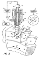
- an electroerosion machine or apparatus 10 including a tubular cutting tool or electrode 12.
- the apparatus includes a multiaxis, numerically controlled (NC) machine 14 which includes a tool head 16 that supports the electrode for rotation or spinning S thereof, and multiple axes of movement during operation.
- NC numerically controlled
- the machine also includes a suitable support table in the exemplary form of a rotary spindle 18 which supports a workpiece 20, preferably with an additional axis of movement.
- Means in the form of a conventional direct current (DC) power supply 22 are provided for carrying electrical power through the electrode 12 and workpiece 20 during operation.
- the power supply includes suitable electrical leads 24 correspondingly joined to the electrode 12 as a cathode (-) and the workpiece as an anode (+) in one embodiment.
- the polarity may be reversed with an anode electrode and a cathode workpiece.
- the electrical lead therefor may be suitably joined thereto using a conventional electrical slip ring or other connection as desired. And, the lead for the workpiece may be directly attached thereto or to the supporting spindle 18 as desired.
- an electrolyte supply 26 for circulating an electrically conductive liquid or electrolyte 30 through the electrode 12 during operation.
- the electrolyte supply includes various conduits 28 for supplying clean and cool electrolyte to the electrode while returning debris-laden electrolyte from the machining site.
- the electrolyte may be plain water, or oil, or other liquid having weak to strong electrical conductivity as desired.
- Means in the form of a digitally programmable electrical controller 32 are operatively joined to the NC machine 14 for controlling its operation, and additionally joined to the DC power supply 22 for also controlling its operation, and coordinating relative movement between the electrode and the workpiece during the electroerosion machining process.
- the controller 32 may have any conventional form and includes a central processing unit (CPU) and all attendant memory and data handling systems which may be programmed using suitable software for controlling all operations of the apparatus.
- CPU central processing unit
- a monitor and keyboard are provided with the controller for use both by the operator in controlling the electroerosion machining process, as well as by the programmer for initially setting up the machine for specific forms of workpieces.
- the electroerosion apparatus is illustrated in more detail in Figure 2 associated with the corresponding process or method of electroerosion of the workpiece 20.
- the process includes feeding the spinning tubular electrode 12 along a feedpath (P) across the workpiece 20, which is preferably held stationary.
- the electrolyte 30 is circulated through the spinning electrode and out through the tip 34 thereof closely adjacent to the workpiece being machined.
- the spinning electrode 12 is powered by the power supply 22 as a cathode while the workpiece is powered as an anode for electroeroding a corresponding slot 36 through the workpiece corresponding generally with the size of the cutting electrode itself.
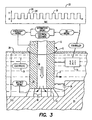
- Figure 3 illustrates further enlarged the tip end of the electrode 12 as it electroerodes the slot 36 in the workpiece.
- the controller 32 is specifically configured for powering the spinning electrode 12 with a DC pulsed train or waveform 38 which has the technical effect of distributing spatially multiple electrical arcs 40 between the electrode tip 34 and the workpiece 20 for controlled electroerosion machining thereof.
- the spinning electrode 12 travels along the programmed feedpath P through the workpiece, electrical power is carried through the electrode and the electrolyte in the small gap G maintained between the electrode tip and the workpiece for electrically eroding material from the workpiece to form the corresponding slot.
- the production of electrical arcs in conventional EDM and ECM processes is strictly prohibited therein due to the associated damage therefrom.
- the corresponding electrical controllers thereof include circuits specifically configured for detecting arcing or incipient arcing, to thereby prevent or terminate arcing during operation.
- the electroerosion process illustrated schematically in Figure 3 intentionally effects electrical arcing which is preferentially distributed spatially over the electrode tip during operation for substantially increasing the rate of material removal from the workpiece.
- the controller 32 is specifically configured for controlling the power supply 22 to power the spinning electrode with the DC pulse voltage waveform 38, while also controlling the multiaxis machine 14 to adjust the electrode travel through the workpiece and effect temporally intermittent, or transient, multiple electrical arcs between the electrode and workpiece.
- Figure 3 also illustrates schematically that the controller 32 is configured between two extremes of operation to prevent no-arcing between the electrode and workpiece as represented by the no-arcing box with the diagonal line therethrough, and to prevent persistent or steady-state arcing similarly represented by the box with the diagonal line therethrough.
- the DC pulse waveform 38 effects a train of on and off DC voltage pulses to power the electroerosion process through the electrode tip.
- the electrical power is carried through the electrolyte 30 in the gap G between the electrode tip and the workpiece.
- the generation of the electrical arcs is random from pulse to pulse, but is nevertheless statistically repetitive and statistically controllable.
- control of the power supply may be coordinated with the feedpath travel P of the electrode for effecting intermittent multiple electrical arcs 40 between the electrode tip and workpiece temporally alternating with electrical discharges between the electrode and workpiece without electrical arcing.
- the increase of material removal attributed to the multiple electrical arcs may be balanced with the resulting recast layer by alternating arcing with non-arcing electrical discharges. This balance may be determined for particular workpieces and particular machining processes empirically using both analysis and a series of test machining.
- clean and cool electrolyte 30 is channeled internally through the tubular electrode and out the orifice in the center of the electrode tip for providing clean and cool electrolyte in the machining gap G for promoting stability and distribution of the multiple electrical arcs.
- the electrolyte also flushes away the erosion debris from the machining process.
- a substantial increase in the electrical current may be used with the spinning electrode with a correspondingly lower peak current density due to the generation of the distributed multiple arcs, which combine to substantially increase the rate of material removal relative to conventional ECM and EDM machining processes.
- the tool head 16 shown in Figure 1 is preferably supported in the multiaxis machine 14 with three axes X,Y,Z of linear and orthogonal translation, and one or more axes of rotation A such as that found around the linear axis X.
- the X axis is parallel to the plane of the exemplary workpiece 20 and normal to the spindle axis.
- the Y axis is parallel to the spindle axis and is in a horizontal plane with the X axis.
- the Z axis is vertical.
- the tool head 16 may be mounted in the machine in any conventional manner for achieving these exemplary axes of movement, and is typically effected using suitable screw driven carriages powered by corresponding electrical servomotors.
- the various servomotors for the movement axes are operatively joined to the controller 32 which coordinates the movement thereof to in turn control the feedpath P of the electrode tip during operation. In this way, the electrode tip may follow a precise 3D feedpath through the workpiece as desired for machining complex 3D contours in the workpiece.
- the spindle 18 illustrated in Figure 1 is supported in the multiaxis machine 14 with a rotary axis B of movement effected by a corresponding servomotor.
- the B axis servomotor is also operatively joined to the controller 32 for preferably periodic rotational indexing of the exemplary workpiece 20 as required during operation.
- the exemplary workpiece illustrated in Figure 1 is in the form of an annular blisk blank, and the spindle 18 is configured for supporting the blank 20 coaxially thereon.
- the spindle 18 is in the form of a shaft, and the blisk blank has a center bore which may be mounted using a suitable fixture fixedly attached to the spindle for rotation therewith during operation.
- the controller 32 is correspondingly configured for driving the spinning electrode 12 along arcuate feedpaths P as illustrated in more detail in Figure 2 axially through the outer perimeter of the blisk blank 20 for forming rough airfoils 42 extending radially outwardly from the perimeter of the workpiece relative to the centerline axis of the supporting spindle.
- the controller 32 is further configured for driving the electrode 12 in successively radially deeper feedpaths axially through the workpiece 20 for electroerosion machining discrete rough airfoils 42 in turn in the blank.
- the slots 36 are therefore machined radially deeper from the outer perimeter of the workpiece for the desired full height of the resulting rough airfoils 42, which airfoils 42 are formed after machining complete slots on opposite sides thereof.
- the rough airfoils 42 so machined include sufficient additional material thereon for undergoing a subsequent machining operation for removing the rough finish thereof and the thin recast layer for achieving the final dimension and smooth surface finish for the final airfoils of the blisk.
- the controller 32 is preferably additionally configured for compensating for this wear of the electrode which decreases the length thereof.
- the controller may be configured for calculating wear per machining pass of the electrode and correspondingly adjusting the radial position of the electrode as the electrode completes each of its feedpath passes through the perimeter of the workpiece.
- the small gap G between the electrode tip and workpiece may be maintained substantially constant during the machining process, but is dynamically varied by the controller to control efficacy and stability of the multiarc erosion process.
- the multiaxis machine 14 preferably includes one or more reference planes 44,46 associated with the length of the electrode 12.
- the controller 32 may then be further configured for touching the electrode tip 34 against the reference plane prior to or immediately after each of the successive feedpaths through the workpiece, or at other intervals, to calibrate the radial position of the electrode tip.
- an accurate indication of the position of the electrode tip, and corresponding length of the electrode may be stored in the controller for each pass of the electrode to improve the accuracy of the wear compensation of the electrode during machining.
- the tip position may otherwise be detected by other suitable means, such as by laser detection.
- the electrode 12 illustrated in Figure 1 is slender or elongate, and is relatively long and thin with a suitable diameter for the intended workpiece. Sufficient length is provided in the electrode for compensating for the wear of the electrode during operation which reduces its length, with the electrode having a suitable length to diameter ratio initially greater than about 5 for example.
- the tool head 16 illustrated in Figure 1 includes a lower tubular guide 48 for coaxially supporting the lower end of the electrode 12, with the lower distal tip 34 of the electrode being suspended therebelow and directly atop the workpiece.
- the lower guide supports the lower end of the electrode for rotary movement therein.
- the multiaxis machine 14 further includes a rotary collet or chuck 50 suitably joined to an upper extension of the tool head 16 above the lower guide for supporting and rotating or spinning the opposite top or proximal end of the elongate electrode 12.
- a rotary collet or chuck 50 suitably joined to an upper extension of the tool head 16 above the lower guide for supporting and rotating or spinning the opposite top or proximal end of the elongate electrode 12.
- the top of the electrode is mounted in the spinning chuck, and the bottom of the electrode is mounted through the lower guide for permitting spinning thereof during operation.
- the tool head 16 illustrated in Figure 1 preferably also includes a middle tubular guide 52 disposed longitudinally between the upper chuck 50 and the lower guide 48.
- the middle guide 52 coaxially supports an intermediate portion of the electrode 12 for restraining wobbling or radial flexing thereof during operation. In this way, accurate position of the electrode tip may be maintained during the machining process by maintaining the long, spinning electrode straight.
- the chuck 50 illustrated in Figure 1 is preferably mounted on the common tool head 16 for selective elevation movement C thereon to push or index the electrode 12 downwardly through the lower guide 48 as the electrode wears at the tip 34 thereof.
- the chuck may be mounted in a suitable carriage powered by another servomotor for precisely controlling the vertical elevation of the proximal end of the electrode, and in turn controlling the vertical location of the lower electrode tip.
- the electrode may be continually indexed lower as its length is reduced.
- the machining process is temporarily interrupted for replacing the electrode with a new and longer electrode, and repositioning the chuck 50 to the top of its travel path.
- the lower guide 48 is illustrated in a preferred embodiment in Figure 2 and includes a ceramic bushing 54 coaxially mounted therein in a suitable bore for coaxially supporting the electrode 12 extending therethrough.
- the ceramic bushing is wear resistant to the rotating electrode for ensuring its accurate support during spinning operation.
- the lower guide may be made from multiple parts, including a main body in which the ceramic bushing 54 may be mounted, and covered by a removable lid fastened thereto by bolts.
- a lower body extends downwardly from the main body of the lower guide through a corresponding aperture in the tool head 16 for retention thereon.
- the lower guide may be formed of stainless steel to resist corrosion from the electrolyte, and has a center bore spaced suitably outwardly from the electrode to provide a small radial gap therebetween, with the electrode being radially supported by the close fitting ceramic bushing 54 disposed therearound.
- the lower guide may have a length to diameter ratio greater than about 3 for ensuring stable support of the lower end of the electrode during operation.
- the middle guide 52 may be similarly configured with a trapped ceramic bushing therein for supporting the intermediate portion of the electrode during operation.
- the middle guide as illustrated in Figure 1 is suitably supported from an additional arm of the tool head 16, which is adjustable in elevation as desired for minimizing any wobbling of the slender electrode during operation.
- the lower guide 48 preferably also includes a row of radial or inclined inlet holes 56 extending laterally therethrough to the center bore thereof, and joined in flow communication to the electrolyte supply 26.
- the supply conduit 28 may be fixedly joined to the lower arm of the tool head 16 through which the lower guide 48 is mounted to provide a common annular manifold around the row of inlet holes 56 for supplying electrolyte thereto under suitable pressure.
- the proximal end of the electrode 12 is suitably joined to the conduit 28 in flow communication with the electrolyte supply 26 for channeling the electrolyte through the electrode.
- the electrolyte is internally channeled through the electrode and discharged out the bore of the electrode tip to locally flush the gap between the tip and workpiece during operation.
- the electrolyte supply 26 illustrated in Figure 1 includes various pipes or conduits for circulating the electrolyte to and from the cutting region of the spinning electrode, and corresponding pumps therefor.
- the electrolyte supply includes two stage filters 58,60 for successively filtering from the electrolyte relatively large or rough and relatively small or fine erosion debris generated during the electroerosion of the workpiece.
- the electrolyte supply preferably also includes a work tank 62 containing the spindle 18 and workpiece mounted thereto.
- the tank is sized for being filled with electrolyte 30 in a pool to submerge the workpiece 20 and the electrode tip during the electroerosion process.
- the bottom of the tank may be suitably connected to the rough filter 58 for removing the large debris particles from the electrolyte.
- the rough filter is in turn joined in flow communication with the fine filter 60 for removing even smaller debris particles.
- the upper portion of the tank 62 may be directly joined to the fine filter and bypassing the rough filter.
- the rough and fine filters 58,60 may have any suitable configuration, such as a filtering conveyor belt in the rough filter 58, and rolled paper filters for the fine filter for effectively removing erosion debris from the electrolyte prior to return to the spinning electrode. Suitable cooling of the electrolyte may also be provided to remove therefrom heat generated during the electroerosion process.
- the two stage filters 58,60 are preferably joined in flow communication with the electrode 12 for effecting both internal and external flushing thereof to enhance the stability of the intermittent multiple electrical arcs generated at the tip end of the electrode during operation.
- Internal flushing is provided by channeling a portion of the electrolyte through the center bore of the electrode and out its tip end.
- external flushing is provided by channeling another portion of the electrolyte through the lower guide 48 as indicated above, while also optionally bathing the entire workpiece in the bath of electrolyte contained in the work tank 62.
- the power supply 22 is configured for generating DC voltage in the preferred range of about 20 to 60 volts, which is typically greater than the voltage range for conventional ECM and generally less than the voltage range for conventional EDM.
- the power supply is further configured for generating relatively high electrical current in the exemplary range of about 80 to 600 amps, with a correspondingly high average current density in the range of 1900 to 12,000 amps per square inches (295-1860 amps per square centimeter).
- the relatively high current and average density thereof promote correspondingly large electroerosion material removal, with the additional advantage of relatively low peak current density of about 1000 amps per square inch (155 amps per square centimeter).
- the low peak current density is attributable to the multiple electrical arcs distributed over the entire cutting area of the electrode tip, as opposed to a single electrical arc.
- the low peak current density minimizes the production of the recast layer in the surface of the machine workpiece and prevents unacceptable heat affected damage thereto.
- the low peak current density may be compared to the high peak current density of multiple orders of magnitude greater in conventional EDM machining in the event of the generation of an electrical arc therein.
- EDM electrowetting-on-dielectric liquid
- a dielectric liquid is used between the electrode and workpiece and promotes a single electrical discharge or arc in which the entire electrical current is dissipated. That single high current arc has the potential to cause significant damage unless it is avoided or terminated in its incipiency.
- the power supply 22 illustrated in Figure 3 is under the control of the controller 32 and is preferably also configured for effecting a DC voltage pulse train having a voltage on-time in the range of about 300 to 1500 microseconds.
- the DC voltage pulse train preferably also has a voltage off-time in the range of about 110 to 1,000 microseconds.
- pulse on and off times may be adjusted by the controller during the electroerosion process to control the generation of the intermittent multiple electrical arcs from the electrode tip alternating with electrical discharges without arcing.
- the alternating arcs and discharges may be balanced by maximizing the electroerosion removal rate while minimizing recast or heat affected surface layers on the workpiece.
- the controller 32 may be preferentially configured for coordinating power to the spinning electrode 12 and the rate of movement or feedrate thereof across the workpiece for electroerosion machining the slot 36 at a machining rate exceeding about 1500 cubic millimeters per minute, without undesirable thermal damage or recast layers in the workpiece.
- testing indicates a substantially high material removal rate for the exemplary superalloy Inconel 718 blisk workpiece of 1500 cubic millimeters per minute for an electrode with 120 amp current and having a diameter of about 7.5 millimeters, with a corresponding frontal electrode area of 22 square millimeters.
- Testing additionally indicates a removal rate of about 2000 cubic millimeters per minute for an electrode having a 13 millimeter diameter with a corresponding frontal electrode area of about 52 square millimeters.
- testing further indicates a removal rate of about 3000 cubic millimeters per minute for an electrode having a 20 millimeter diameter and a corresponding frontal electrode area of about 80 square millimeters.
- electroerosion of the workpiece may be effected more quickly than previously possible, without undesirable damage thereto, for reducing both the time and expense associated in the manufacture of the workpiece, which is particularly significant for complex and expensive workpieces such as the exemplary gas turbine engine rotor blisk disclosed above.
Landscapes
- Engineering & Computer Science (AREA)
- Mechanical Engineering (AREA)
- Physics & Mathematics (AREA)
- Chemical & Material Sciences (AREA)
- Chemical Kinetics & Catalysis (AREA)
- Electrochemistry (AREA)
- Plasma & Fusion (AREA)
- Thermal Sciences (AREA)
- Electrical Discharge Machining, Electrochemical Machining, And Combined Machining (AREA)
Claims (10)
- Appareil d'électroérosion (10), comprenant :une électrode tubulaire (12) ;une machine à axes multiples (14), comportant une tête porte-outil (16), supportant ladite électrode, pour faire tourner celle-ci avec des axes multiples de déplacement et une broche (18), destinée à supporter une pièce à usiner (20), avec un axe supplémentaire de déplacement ;une alimentation en courant (22), comportant des fils d'amenée (24), destinés à acheminer le courant dans ladite électrode (12) et la pièce à usiner (20) ;une alimentation (26) d'électrolyte, comportant un conduit (28), destiné à faire circuler un électrolyte (30) dans ladite électrode (12),caractérisé parun contrôleur (32), couplé de manière opérationnelle à ladite machine à axes multiples (14) et à ladite alimentation en courant (22) pour le contrôle de celles-ci et configuré pour distribuer des arcs électriques multiples intermittents (40) entre ladite électrode (12) et la pièce à usiner (20), en alternant temporairement avec des décharges électriques entre celles-ci sans formation d'un arc électrique.
- Appareil selon la revendication 1, dans lequel :ladite tête porte-outil (16) est supportée dans ladite machine à axes multiples (14) avec trois axes de translation linéaire et un axe de rotation et couplée de manière opérationnelle audit contrôleur (32) pour un déplacement coordonné de celle-ci, pour contrôler ladite trajectoire d'avance de ladite électrode (12) etladite broche (18) est supportée dans ladite machine à axes multiples (14) avec un axe de rotation de déplacement et est couplée de manière opérationnelle audit contrôleur (32), pour indexer à rotation ladite pièce à usiner (20).
- Appareil selon la revendication 2, dans lequel ledit contrôleur (32) est configuré, en outre, pour piloter ladite électrode (12) dans des trajectoires d'avance successivement plus profondes dans ladite pièce à usiner (20), pour électro-usiner des rainures (36) au travers.
- Appareil selon la revendication 3, dans lequel ledit contrôleur (32) est configuré, en outre, pour compenser l'usure de ladite électrode (12), qui diminue la longueur de celle-ci.
- Appareil selon la revendication 4, dans lequel :ladite électrode (12) est mince ;ladite tête porte-outil (16) comporte un guide tubulaire inférieur (48), destiné à supporter une extrémité inférieure de ladite électrode (12), un bout distal inférieur (34) de celle-ci étant suspendue au-dessous etladite machine à axes multiples (14) comporte, en outre, un mandrin rotatif (50), couplé à ladite tête porte-outil (16), au-dessus dudit guide inférieur (48), pour supporter et faire tourner une extrémité proximale opposée de ladite électrode (12).
- Appareil selon la revendication 5, dans lequel ladite tête porte-outil (16) comporte, en outre, un guide tubulaire central (52), disposé entre ledit mandrin (50) et le guide inférieur (48), pour supporter une partie intermédiaire de ladite électrode (12).
- Appareil selon la revendication 6, dans lequel ledit guide inférieur (48) comporte une rangée de trous d'entrée (56), s'étendant latéralement au travers vers l'alésage de ceux-ci et couplée en communication d'écoulement avec ladite alimentation (26) d'électrolyte, pour canaliser ledit électrolyte au travers.
- Appareil selon la revendication 7, dans lequel ladite extrémité proximale de ladite électrode (12) est couplée, en communication d'écoulement, avec ladite alimentation (26) d'électrolyte, pour canaliser ledit électrolyte dans ladite électrode pour une décharge du bout (34) de ladite électrode.
- Appareil selon l'une quelconque des revendications précédentes, dans lequel ledit contrôleur (32) est configuré, en outre, pour contrôler ladite alimentation en courant (22), pour alimenter ladite électrode (12) avec une forme d'onde d'impulsion (38) en courant continu (CC) et contrôler ladite machine à axes multiples (14), pour ajuster le parcours de ladite électrode dans ladite pièce à usiner et produire des arcs électriques multiples intermittents entre ladite électrode et ladite pièce à usiner.
- Procédé d'usinage par électroérosion d'une pièce à usiner (20), comprenant les opérations, consistant à :faire avancer une électrode tubulaire pivotante (12) le long d'une trajectoire d'avance dans toute ladite pièce à usiner (20) ;faire circuler un électrolyte (30) dans ladite électrode pivotante vers le bout (34) de celle-ci, attenant à ladite pièce à usiner ;filtrer ledit électrolyte de circulation (30), pour enlever les débris d'électroérosion de celui-ci,caractérisé par l'opération, consistant àalimenter ladite électrode pivotante (12) et ladite pièce à usiner avec une forme d'onde pulsée (38) en CC, destinée à distribuer des arcs électriques multiples intermittents entre le bout (34) de ladite électrode et ladite pièce à usiner, en alternant temporairement avec des décharges électriques entre le bout de ladite électrode pivotante et ladite pièce à usiner, sans former d'arc électrique, pour usiner par électroérosion une rainure (36) dans ladite pièce à usiner.
Applications Claiming Priority (2)
| Application Number | Priority Date | Filing Date | Title |
|---|---|---|---|
| US842344 | 1986-03-21 | ||
| US10/842,344 US20050247569A1 (en) | 2004-05-07 | 2004-05-07 | Distributed arc electroerosion |
Publications (3)
| Publication Number | Publication Date |
|---|---|
| EP1593449A2 EP1593449A2 (fr) | 2005-11-09 |
| EP1593449A3 EP1593449A3 (fr) | 2006-01-18 |
| EP1593449B1 true EP1593449B1 (fr) | 2013-01-02 |
Family
ID=34941090
Family Applications (1)
| Application Number | Title | Priority Date | Filing Date |
|---|---|---|---|
| EP05252662A Active EP1593449B1 (fr) | 2004-05-07 | 2005-04-28 | Electroérosion avec un arc distribué |
Country Status (4)
| Country | Link |
|---|---|
| US (2) | US20050247569A1 (fr) |
| EP (1) | EP1593449B1 (fr) |
| JP (1) | JP5789070B2 (fr) |
| CN (1) | CN100591452C (fr) |
Families Citing this family (64)
| Publication number | Priority date | Publication date | Assignee | Title |
|---|---|---|---|---|
| DE10326719A1 (de) * | 2003-06-06 | 2004-12-23 | Rolls-Royce Deutschland Ltd & Co Kg | Verdichterschaufelfuß für Triebwerksschaufeln von Flugzeugtriebwerken |
| DE102004013031A1 (de) * | 2004-03-16 | 2005-10-06 | Waldrich Siegen Werkzeugmaschinen Gmbh | Verfahren und Maschine zur Herstellung einer Walze |
| US20050218089A1 (en) * | 2004-03-30 | 2005-10-06 | General Electric Company | Flushing and filtering system for electroerosion machining |
| US20050247569A1 (en) * | 2004-05-07 | 2005-11-10 | Lamphere Michael S | Distributed arc electroerosion |
| DE102004036598A1 (de) * | 2004-07-28 | 2006-03-23 | Mtu Aero Engines Gmbh | Verfahren zum Herstellen aerodynamischer Strukturen bei der Fertigung von integral beschaufelten Gasturbinenrotoren |
| US8070933B2 (en) * | 2005-05-06 | 2011-12-06 | Thielenhaus Microfinishing Corp. | Electrolytic microfinishing of metallic workpieces |
| GB0513465D0 (en) * | 2005-07-01 | 2005-08-10 | Elekta Ab | Manufacture of multi-leaf collimators |
| US20080210571A1 (en) * | 2006-08-24 | 2008-09-04 | Extrude Hone Corporation | Machine And Method For Electrochemically Polishing Indentations Within An Aluminum Wheel |
| US7824526B2 (en) * | 2006-12-11 | 2010-11-02 | General Electric Company | Adaptive spindle assembly for electroerosion machining on a CNC machine tool |
| US20080142488A1 (en) * | 2006-12-19 | 2008-06-19 | General Electric Company | Compound electrode, methods of manufacture thereof and articles comprising the same |
| US7741576B2 (en) * | 2007-05-11 | 2010-06-22 | General Electric Company | Apparatus and method for hybrid machining a workpiece |
| US7976694B2 (en) * | 2007-07-17 | 2011-07-12 | General Electric Company | Apparatus and method for hybrid machining a contoured, thin-walled workpiece |
| JP5301125B2 (ja) * | 2007-08-03 | 2013-09-25 | ゼネラル・エレクトリック・カンパニイ | 複合電気機械加工方法 |
| CN101468416B (zh) * | 2007-12-25 | 2013-01-02 | 通用电气公司 | 电腐蚀加工主轴系统 |
| US20100030365A1 (en) * | 2008-07-30 | 2010-02-04 | Pratt & Whitney | Combined matching and inspection process in machining of fan case rub strips |
| US9333577B2 (en) * | 2008-08-29 | 2016-05-10 | General Electric Company | Electro discharge machining apparatus and method |
| US8236162B2 (en) * | 2008-09-30 | 2012-08-07 | General Electric Company | Electroerosion machining system and method for electrode wear compensation |
| ATE506136T1 (de) * | 2008-11-04 | 2011-05-15 | Siemens Ag | Vorrichtung und verfahren zum herstellen von bohrungen in einer kante einer turbinenschaufel |
| US20100163427A1 (en) * | 2008-12-31 | 2010-07-01 | Yimin Zhan | Methods and systems for electromachining of a workpiece |
| GB2467523A (en) * | 2009-01-30 | 2010-08-04 | Cummins Turbo Tech Ltd | Method for manufacturing turbine wheels |
| DE102009022926B4 (de) * | 2009-05-27 | 2011-09-15 | Mtu Aero Engines Gmbh | Elektrode zur elektrochemischen Bearbeitung eines Werkstücks |
| US8560110B2 (en) | 2009-06-19 | 2013-10-15 | General Electric Company | Electroerosion control system and a dual mode control system |
| US8535491B2 (en) * | 2009-09-18 | 2013-09-17 | General Electric Company | Electrochemical machining assembly with curved electrode |
| IT1396512B1 (it) | 2009-10-21 | 2012-12-14 | Nuovo Pignone Spa | Metodo e dispositivo per compensazione di utensile |
| CN102133666B (zh) * | 2010-01-22 | 2014-08-20 | 通用电气公司 | 刀具接头组件及加工系统 |
| CN102398093B (zh) | 2010-09-14 | 2014-09-24 | 通用电气公司 | 加工系统和方法 |
| DE102011014364A1 (de) * | 2011-03-17 | 2012-09-20 | Stoba Präzisionstechnik Gmbh & Co. Kg | Verfahren und Vorrichtung zum elektrochemischen Bearbeiten von Werkstücken |
| CA2845752C (fr) * | 2011-08-18 | 2016-07-12 | Victor Equipment Company | Systeme a l'arc avec electrode de carbone et jet d'air pour la detection et/ou la reduction d'irregularites dans la surface une piece a travailler et son procede d'utilisation |
| GB201200360D0 (en) * | 2012-01-11 | 2012-02-22 | Rolls Royce Plc | Component production method |
| CN103240473B (zh) | 2012-02-07 | 2015-08-19 | 通用电气公司 | 电极及其制造方法 |
| US20140001158A1 (en) * | 2012-06-27 | 2014-01-02 | General Electric Company | Systems and methods for repairing encased components |
| CN102909443B (zh) * | 2012-09-29 | 2014-09-17 | 北京迪蒙数控技术有限责任公司 | 涡轮盘电火花成形加工及在线检测装置 |
| CN103521861B (zh) * | 2013-09-29 | 2015-10-28 | 南京航空航天大学 | 基于三维复合流场的整体叶盘型面电解加工装置及方法 |
| FR3015554B1 (fr) * | 2013-12-19 | 2016-01-29 | Snecma | Secteur d'anneau de turbine pour turbomachine d'aeronef, presentant des orifices de prehension ameliores |
| TWI594826B (zh) * | 2014-02-13 | 2017-08-11 | 國立高雄應用科技大學 | 複合式微放電研磨加工機台 |
| CN103817388B (zh) * | 2014-03-04 | 2017-07-28 | 山东理工大学 | 一种制备螺旋型硬质合金微细铣刀的装置 |
| CN105081491A (zh) | 2014-05-15 | 2015-11-25 | 通用电气公司 | 加工系统及用于其上的刀具固持装置 |
| CN104084654B (zh) * | 2014-07-15 | 2016-08-31 | 上海交通大学 | 六轴联动空间摇动电火花加工方法 |
| US10022812B2 (en) * | 2014-10-09 | 2018-07-17 | General Electric Company | Methods for the electroerosion machining of high-performance metal alloys |
| CN104646773B (zh) * | 2014-11-11 | 2016-08-24 | 新疆短电弧科技开发有限公司 | 一种短电弧便携可移动放电加工系统 |
| WO2016136940A1 (fr) * | 2015-02-27 | 2016-09-01 | 国立大学法人東京大学 | Dispositif d'usinage électrochimique et procédé d'usinage électrochimique |
| US9346113B1 (en) * | 2015-03-19 | 2016-05-24 | Johnson Technology, Inc. | Electrical discharge machining integrated control system |
| CN104772535B (zh) * | 2015-04-09 | 2017-07-18 | 上海交通大学 | 开放式三维流道高速电弧放电层扫加工方法 |
| CN106141340A (zh) | 2015-04-24 | 2016-11-23 | 通用电气公司 | 轮廓加工方法及用该方法加工的零件 |
| CN104959686A (zh) * | 2015-06-01 | 2015-10-07 | 苏州市宝玛数控设备有限公司 | 一种电火花线切割加工铝合金的工艺改进方法 |
| DE102015216844A1 (de) * | 2015-09-03 | 2017-03-09 | MTU Aero Engines AG | Vorrichtung und Verfahren zur Herstellung eines Schaufelblattes |
| CN106552975B (zh) * | 2015-09-28 | 2019-01-01 | 通用电气公司 | 加工工具和加工系统 |
| CN105537786B (zh) * | 2016-03-04 | 2018-02-02 | 北方工业大学 | 一种旋转超声辅助电磁激励调制高效电弧加工方法 |
| ITUA20162126A1 (it) * | 2016-03-30 | 2017-09-30 | Exergy Spa | Metodo per la costruzione di dischi palettati per turbomacchine radiali e disco palettato ottenuto tramite tale metodo |
| US10245666B2 (en) | 2016-06-30 | 2019-04-02 | General Electric Company | Drilling tool for use in machining a conductive work piece |
| CN107876912B (zh) * | 2017-11-29 | 2019-08-16 | 中山市榄商置业发展有限公司 | 一种大尺寸多轴联动电解加工机床 |
| CN108380989B (zh) * | 2018-03-28 | 2024-04-23 | 北京汉飞航空科技有限公司 | 一种航空发动机整体叶盘的加工方法及设备 |
| EP3552746A1 (fr) * | 2018-04-10 | 2019-10-16 | Siemens Aktiengesellschaft | Dispositif d'usinage électrochimique sélectif de pièces à usiner et installation d'usinage d'une pièce à usiner au moyen d'un tel dispositif |
| KR102135212B1 (ko) * | 2018-10-24 | 2020-07-17 | (주)애니캐스팅 | 전해생성물 제거가 가능한 전해가공장치 |
| CN109226778B (zh) * | 2018-11-15 | 2024-01-30 | 深圳创源航天科技有限公司 | 一种金属粉末颗粒制备装置 |
| CN109848493B (zh) * | 2019-01-30 | 2021-01-01 | 上海交通大学 | 一种基于放电加工的多功能集成制造系统 |
| CN109746534B (zh) * | 2019-02-18 | 2021-04-30 | 上海交通大学 | 基于电弧放电和铣削组合的叶盘类零件加工系统和方法 |
| CN109926670B (zh) * | 2019-04-12 | 2024-04-19 | 南京宁庆数控机床制造有限公司 | 电解加工机床的主轴结构 |
| DE102019210905A1 (de) * | 2019-07-23 | 2021-01-28 | MTU Aero Engines AG | Verfahren und Vorrichtung zum Bearbeiten von Bauteilen durch elektrochemisches Abtragen |
| CN110605445B (zh) * | 2019-08-16 | 2020-08-21 | 南京航空航天大学 | 一种非匀速双旋转整体叶盘叶栅通道电解加工方法 |
| CN110935968B (zh) * | 2019-12-04 | 2020-08-18 | 合肥工业大学 | 一种整体叶盘一体化电解加工的方法及电解工具 |
| CN112171010B (zh) * | 2020-10-09 | 2021-06-04 | 昆山宝锦激光拼焊有限公司 | 一种测量洞口大小且焊接设备 |
| US20220212276A1 (en) * | 2021-01-06 | 2022-07-07 | General Electric Company | Contact matrix for grounding a ceramic component during electrical discharge machining |
| CN113118573A (zh) * | 2021-03-09 | 2021-07-16 | 广东工业大学 | 一种管电极电解铣削加工深窄槽的方法及装置 |
Citations (2)
| Publication number | Priority date | Publication date | Assignee | Title |
|---|---|---|---|---|
| EP1166936A2 (fr) * | 2000-06-23 | 2002-01-02 | The Nottingham Trent University | Utilisation de rétroaction acoustive dans le contrôle d'une machine d'usinage par électroérosion |
| US20030173337A1 (en) * | 2002-03-14 | 2003-09-18 | Tetsuro Ito | Electric sparking drill and method for forming a hole with an electric spark |
Family Cites Families (54)
| Publication number | Priority date | Publication date | Assignee | Title |
|---|---|---|---|---|
| US3417006A (en) * | 1965-01-20 | 1968-12-17 | Inoue Kiyoshi | Method of and apparatus for electrical machining of metallic workpieces |
| US3591761A (en) * | 1968-07-05 | 1971-07-06 | Ibm | Pattern and cavity electroerosion by repeated raster scanning |
| JPS5142682B2 (fr) * | 1972-02-18 | 1976-11-17 | ||
| US4159407A (en) * | 1974-03-23 | 1979-06-26 | Rolls-Royce (1971) Limited | Methods and apparatus for electrically machining a work piece |
| DE7330369U (de) * | 1975-07-31 | 1976-03-18 | Languepin, Carel Fouche, Paris | VorrichtUng zur elektrischen Bearbeitung von Werkstücken |
| US4441005A (en) * | 1980-05-06 | 1984-04-03 | Sodick Co., Ltd. | EDM Pulse generator with a variable output inductor for producing pulse with gradually rising edges |
| US4697059A (en) * | 1980-08-14 | 1987-09-29 | Sodick Co., Ltd. | Apparatus for pattern controlled electrode movement for E.D.M. |
| US4521332A (en) * | 1981-03-23 | 1985-06-04 | Pennwalt Corporation | Highly alkaline cleaning dispersion |
| JPS57168833A (en) * | 1981-04-03 | 1982-10-18 | Hitachi Seiko Ltd | Detecting method of electric discharge machining condition |
| JPS5850414A (ja) * | 1981-09-21 | 1983-03-24 | Japax Inc | ジヤパツクス株式会社 |
| JPS5877414A (ja) * | 1981-11-02 | 1983-05-10 | Inoue Japax Res Inc | 電気加工用加工液及びこの加工液を使用する電気加工方法 |
| US4534831A (en) * | 1982-09-27 | 1985-08-13 | Inoue-Japax Research Incorporated | Method of and apparatus for forming a 3D article |
| JPS5976720A (ja) * | 1982-10-27 | 1984-05-01 | Inoue Japax Res Inc | 放電加工装置 |
| US4608476A (en) * | 1983-09-22 | 1986-08-26 | Japax Incorporated | Retraction control for 3D-path controlled generic electrode electroerosion |
| ZA85914B (en) * | 1984-02-28 | 1985-09-25 | Westinghouse Electric Corp | Electrode for disintegrating metallic material |
| JPS6161720A (ja) * | 1984-09-03 | 1986-03-29 | Nissan Motor Co Ltd | タ−ビンロ−タの加工方法 |
| JPS61103725A (ja) * | 1984-10-25 | 1986-05-22 | Inoue Japax Res Inc | ワイヤカツト放電加工方法 |
| JPH0794088B2 (ja) * | 1987-03-18 | 1995-10-11 | 工業技術院長 | 電解液中ア−ク放電による非導電性材料の加工法 |
| US4772372A (en) * | 1987-05-13 | 1988-09-20 | General Electric Company | Electrodes for electrochemically machining airfoil blades |
| JPH07121489B2 (ja) * | 1988-03-25 | 1995-12-25 | 工業技術院長 | 電解液中アーク放電を利用した加工の制御方法 |
| CH678156A5 (fr) * | 1989-03-20 | 1991-08-15 | Exnii Metallorezh Stankov | |
| US5128010A (en) * | 1990-08-28 | 1992-07-07 | Liangcai Ye | Apparatus for electrical machining |
| US5115112A (en) * | 1991-02-25 | 1992-05-19 | General Electric Company | Spark erosion machining device and method for correcting for the wear of a machining electrode |
| EP0555818B1 (fr) * | 1992-02-12 | 1995-12-13 | Charmilles Technologies S.A. | Dispositif et procédé pour usiner par électro-érosion une cavité à trois dimensions avec une électrode-outil mince et rotative |
| CH688850A5 (fr) * | 1993-08-19 | 1998-04-30 | Charmilles Technologies | Electrodes-outil pour fraisage par électro-érosion. |
| EP0642867A1 (fr) * | 1993-09-10 | 1995-03-15 | Charmilles Technologies S.A. | Structure pour machine d'électroérosion |
| JPH08108322A (ja) * | 1994-10-12 | 1996-04-30 | Mitsubishi Heavy Ind Ltd | 放電加工装置 |
| JP3645957B2 (ja) * | 1995-12-28 | 2005-05-11 | 株式会社ソディック | 放電加工方法及び装置 |
| JP3217999B2 (ja) * | 1997-12-03 | 2001-10-15 | セイコーインスツルメンツ株式会社 | 部品製作方法及び部品製作装置 |
| US6127642A (en) * | 1998-09-10 | 2000-10-03 | General Electric Company | Flex restrained electrical discharge machining |
| DE19849577C2 (de) * | 1998-10-27 | 2000-12-07 | Agie Sa | Verfahren und Vorrichtung zum dreidimensionalen Bearbeiten eines Werkstücks mittels elektroerosiver oder elektrochemischer Bearbeitung |
| DE60026934T2 (de) * | 1999-06-02 | 2006-12-14 | General Electric Co. | Verfahren zur Verminderung der Wandstärke nach dem Giessen einen Turbinenschaufels mittels Funkenerosionsbearbeitung |
| US20030024122A1 (en) * | 1999-07-29 | 2003-02-06 | Yoshikazu Ichiyama | Method and apparatus for producing hydrodynamic bearing parts by electrochemical machining |
| US6423290B1 (en) * | 2000-05-31 | 2002-07-23 | International Business Machines Corporation | Method for recovering an organic solvent from an acidic waste stream such as in integrated chip manufacturing |
| US6579439B1 (en) * | 2001-01-12 | 2003-06-17 | Southern Industrial Chemicals, Inc. | Electrolytic aluminum polishing processes |
| US7128825B2 (en) * | 2001-03-14 | 2006-10-31 | Applied Materials, Inc. | Method and composition for polishing a substrate |
| US6806435B2 (en) * | 2001-04-12 | 2004-10-19 | Elenix, Inc. | Small hole electric discharge machine drill provided with depth-specific processing means |
| US20020157964A1 (en) * | 2001-04-25 | 2002-10-31 | Hoffman Industries International, Ltd. | System and method for electrolytic cleaning |
| US6562227B2 (en) * | 2001-07-31 | 2003-05-13 | General Electric Company | Plunge electromachining |
| US20030075453A1 (en) * | 2001-10-19 | 2003-04-24 | Dolan Shawn E. | Light metal anodization |
| US7175752B2 (en) * | 2002-05-24 | 2007-02-13 | Federal-Mogul Worldwide, Inc. | Method and apparatus for electrochemical machining |
| US6787728B2 (en) * | 2002-12-27 | 2004-09-07 | General Electric Company | Method and apparatus for near net shape rapid rough electromachining for blisks |
| US6858125B2 (en) * | 2002-12-27 | 2005-02-22 | General Electric Company | Multi-axis numerical control electromachining of bladed disks |
| US6680454B1 (en) * | 2002-12-27 | 2004-01-20 | General Electric Company | Electromachining with perforated electrodes |
| GB0304321D0 (en) * | 2003-02-26 | 2003-04-02 | Bladon Jets Ltd | Fans and turbines |
| US20050121332A1 (en) * | 2003-10-03 | 2005-06-09 | Kochilla John R. | Apparatus and method for treatment of metal surfaces by inorganic electrophoretic passivation |
| US6969817B2 (en) * | 2003-10-15 | 2005-11-29 | General Electric Company | Apparatus and method for machining in confined spaces |
| US6897400B1 (en) * | 2004-03-16 | 2005-05-24 | General Electric Company | Out flushing guide bushing |
| US20050218089A1 (en) * | 2004-03-30 | 2005-10-06 | General Electric Company | Flushing and filtering system for electroerosion machining |
| US20050247569A1 (en) * | 2004-05-07 | 2005-11-10 | Lamphere Michael S | Distributed arc electroerosion |
| US20050273999A1 (en) * | 2004-06-09 | 2005-12-15 | General Electric Company | Method and system for fabricating components |
| US8323473B2 (en) * | 2004-11-23 | 2012-12-04 | General Electric Company | Methods and systems for monitoring and controlling electroerosion |
| US7749567B2 (en) * | 2005-02-28 | 2010-07-06 | Sumitomo Chemical Company, Limited | Process for producing a layered article |
| US20070199829A1 (en) * | 2006-02-28 | 2007-08-30 | Federal-Mogul World Wide, Inc. | Application of tribologically active surface to a metal work-piece using electrochemical machining |
-
2004
- 2004-05-07 US US10/842,344 patent/US20050247569A1/en not_active Abandoned
-
2005
- 2005-04-28 EP EP05252662A patent/EP1593449B1/fr active Active
- 2005-05-02 JP JP2005133810A patent/JP5789070B2/ja active Active
- 2005-05-08 CN CN200510069696A patent/CN100591452C/zh active Active
-
2007
- 2007-06-28 US US11/770,207 patent/US20070256939A1/en not_active Abandoned
Patent Citations (2)
| Publication number | Priority date | Publication date | Assignee | Title |
|---|---|---|---|---|
| EP1166936A2 (fr) * | 2000-06-23 | 2002-01-02 | The Nottingham Trent University | Utilisation de rétroaction acoustive dans le contrôle d'une machine d'usinage par électroérosion |
| US20030173337A1 (en) * | 2002-03-14 | 2003-09-18 | Tetsuro Ito | Electric sparking drill and method for forming a hole with an electric spark |
Also Published As
| Publication number | Publication date |
|---|---|
| CN1693024A (zh) | 2005-11-09 |
| EP1593449A2 (fr) | 2005-11-09 |
| EP1593449A3 (fr) | 2006-01-18 |
| CN100591452C (zh) | 2010-02-24 |
| JP5789070B2 (ja) | 2015-10-07 |
| US20070256939A1 (en) | 2007-11-08 |
| JP2005319577A (ja) | 2005-11-17 |
| US20050247569A1 (en) | 2005-11-10 |
Similar Documents
| Publication | Publication Date | Title |
|---|---|---|
| EP1593449B1 (fr) | Electroérosion avec un arc distribué | |
| US6858125B2 (en) | Multi-axis numerical control electromachining of bladed disks | |
| EP3015207B1 (fr) | Procédés pour l'usinage par électroérosion d'alliages métalliques hautes performances | |
| JP4906229B2 (ja) | ブリスクをニアネットシェイプ高速荒加工するための方法及び装置 | |
| US5651901A (en) | Method and apparatus for surface treatment by electrical discharge machining | |
| EP2170546B1 (fr) | Appareil et procédé permettant un usinage hybride d'une pièce à usiner à paroi mince profilée | |
| US20070228017A1 (en) | Electromachining process and apparatus | |
| JP6865531B2 (ja) | 電食加工システム用の電極 | |
| US8471167B2 (en) | Rough machining electroerosion method for machining a channel in a workpiece | |
| JP2006110697A (ja) | 導電性材料でなる被加工物に任意の形状を加工する方法および複合加工装置 | |
| JP6797457B2 (ja) | 電食加工における材料回収のための方法 | |
| US20090314748A1 (en) | Ultrasonic assisted electrodischarge machining | |
| TWI594826B (zh) | 複合式微放電研磨加工機台 | |
| JPH0521690B2 (fr) | ||
| JP2002254247A (ja) | 型彫り微細放電加工による高効率孔加工方法 |
Legal Events
| Date | Code | Title | Description |
|---|---|---|---|
| PUAI | Public reference made under article 153(3) epc to a published international application that has entered the european phase |
Free format text: ORIGINAL CODE: 0009012 |
|
| AK | Designated contracting states |
Kind code of ref document: A2 Designated state(s): AT BE BG CH CY CZ DE DK EE ES FI FR GB GR HU IE IS IT LI LT LU MC NL PL PT RO SE SI SK TR |
|
| AX | Request for extension of the european patent |
Extension state: AL BA HR LV MK YU |
|
| PUAL | Search report despatched |
Free format text: ORIGINAL CODE: 0009013 |
|
| AK | Designated contracting states |
Kind code of ref document: A3 Designated state(s): AT BE BG CH CY CZ DE DK EE ES FI FR GB GR HU IE IS IT LI LT LU MC NL PL PT RO SE SI SK TR |
|
| AX | Request for extension of the european patent |
Extension state: AL BA HR LV MK YU |
|
| RIC1 | Information provided on ipc code assigned before grant |
Ipc: B23H 9/10 20060101ALI20051125BHEP Ipc: B23H 1/02 20060101AFI20050817BHEP Ipc: B23K 9/013 20060101ALI20051125BHEP Ipc: B23H 7/32 20060101ALI20051125BHEP |
|
| 17P | Request for examination filed |
Effective date: 20060718 |
|
| AKX | Designation fees paid |
Designated state(s): DE FR GB |
|
| 17Q | First examination report despatched |
Effective date: 20080807 |
|
| GRAP | Despatch of communication of intention to grant a patent |
Free format text: ORIGINAL CODE: EPIDOSNIGR1 |
|
| GRAS | Grant fee paid |
Free format text: ORIGINAL CODE: EPIDOSNIGR3 |
|
| GRAA | (expected) grant |
Free format text: ORIGINAL CODE: 0009210 |
|
| AK | Designated contracting states |
Kind code of ref document: B1 Designated state(s): DE FR GB |
|
| REG | Reference to a national code |
Ref country code: GB Ref legal event code: FG4D |
|
| REG | Reference to a national code |
Ref country code: DE Ref legal event code: R096 Ref document number: 602005037685 Country of ref document: DE Effective date: 20130307 |
|
| PLBE | No opposition filed within time limit |
Free format text: ORIGINAL CODE: 0009261 |
|
| STAA | Information on the status of an ep patent application or granted ep patent |
Free format text: STATUS: NO OPPOSITION FILED WITHIN TIME LIMIT |
|
| 26N | No opposition filed |
Effective date: 20131003 |
|
| REG | Reference to a national code |
Ref country code: DE Ref legal event code: R097 Ref document number: 602005037685 Country of ref document: DE Effective date: 20131003 |
|
| REG | Reference to a national code |
Ref country code: FR Ref legal event code: PLFP Year of fee payment: 12 |
|
| REG | Reference to a national code |
Ref country code: FR Ref legal event code: PLFP Year of fee payment: 13 |
|
| REG | Reference to a national code |
Ref country code: FR Ref legal event code: PLFP Year of fee payment: 14 |
|
| PGFP | Annual fee paid to national office [announced via postgrant information from national office to epo] |
Ref country code: FR Payment date: 20200319 Year of fee payment: 16 |
|
| PG25 | Lapsed in a contracting state [announced via postgrant information from national office to epo] |
Ref country code: FR Free format text: LAPSE BECAUSE OF NON-PAYMENT OF DUE FEES Effective date: 20210430 |
|
| PGFP | Annual fee paid to national office [announced via postgrant information from national office to epo] |
Ref country code: GB Payment date: 20240320 Year of fee payment: 20 |
|
| PGFP | Annual fee paid to national office [announced via postgrant information from national office to epo] |
Ref country code: DE Payment date: 20240320 Year of fee payment: 20 |