EP1593416B1 - Set of building blocks - Google Patents
Set of building blocks Download PDFInfo
- Publication number
- EP1593416B1 EP1593416B1 EP04708873.7A EP04708873A EP1593416B1 EP 1593416 B1 EP1593416 B1 EP 1593416B1 EP 04708873 A EP04708873 A EP 04708873A EP 1593416 B1 EP1593416 B1 EP 1593416B1
- Authority
- EP
- European Patent Office
- Prior art keywords
- piece
- groove
- corner edge
- block
- building blocks
- Prior art date
- Legal status (The legal status is an assumption and is not a legal conclusion. Google has not performed a legal analysis and makes no representation as to the accuracy of the status listed.)
- Expired - Lifetime
Links
- 235000012489 doughnuts Nutrition 0.000 description 32
- 230000004048 modification Effects 0.000 description 7
- 238000012986 modification Methods 0.000 description 7
- 238000010586 diagram Methods 0.000 description 3
- 230000006835 compression Effects 0.000 description 2
- 238000007906 compression Methods 0.000 description 2
- 230000001747 exhibiting effect Effects 0.000 description 2
- 230000002349 favourable effect Effects 0.000 description 2
- 230000000007 visual effect Effects 0.000 description 2
- 208000024827 Alzheimer disease Diseases 0.000 description 1
- 206010039966 Senile dementia Diseases 0.000 description 1
- 210000004556 brain Anatomy 0.000 description 1
- 230000001143 conditioned effect Effects 0.000 description 1
- 238000010276 construction Methods 0.000 description 1
- 230000008094 contradictory effect Effects 0.000 description 1
- 239000007799 cork Substances 0.000 description 1
- 230000000694 effects Effects 0.000 description 1
- 230000005484 gravity Effects 0.000 description 1
- 239000000463 material Substances 0.000 description 1
- 238000000034 method Methods 0.000 description 1
- 239000000088 plastic resin Substances 0.000 description 1
- 238000007493 shaping process Methods 0.000 description 1
- 239000002023 wood Substances 0.000 description 1
Images


Classifications
-
- A—HUMAN NECESSITIES
- A63—SPORTS; GAMES; AMUSEMENTS
- A63H—TOYS, e.g. TOPS, DOLLS, HOOPS OR BUILDING BLOCKS
- A63H33/00—Other toys
- A63H33/04—Building blocks, strips, or similar building parts
- A63H33/06—Building blocks, strips, or similar building parts to be assembled without the use of additional elements
- A63H33/08—Building blocks, strips, or similar building parts to be assembled without the use of additional elements provided with complementary holes, grooves, or protuberances, e.g. dovetails
- A63H33/084—Building blocks, strips, or similar building parts to be assembled without the use of additional elements provided with complementary holes, grooves, or protuberances, e.g. dovetails with grooves
-
- A—HUMAN NECESSITIES
- A63—SPORTS; GAMES; AMUSEMENTS
- A63F—CARD, BOARD, OR ROULETTE GAMES; INDOOR GAMES USING SMALL MOVING PLAYING BODIES; VIDEO GAMES; GAMES NOT OTHERWISE PROVIDED FOR
- A63F9/00—Games not otherwise provided for
- A63F9/26—Balancing games, i.e. bringing elements into or out of balance
-
- A—HUMAN NECESSITIES
- A63—SPORTS; GAMES; AMUSEMENTS
- A63F—CARD, BOARD, OR ROULETTE GAMES; INDOOR GAMES USING SMALL MOVING PLAYING BODIES; VIDEO GAMES; GAMES NOT OTHERWISE PROVIDED FOR
- A63F9/00—Games not otherwise provided for
- A63F9/0073—Games for obtaining a particular arrangement of playing pieces in a plane or space
-
- A—HUMAN NECESSITIES
- A63—SPORTS; GAMES; AMUSEMENTS
- A63F—CARD, BOARD, OR ROULETTE GAMES; INDOOR GAMES USING SMALL MOVING PLAYING BODIES; VIDEO GAMES; GAMES NOT OTHERWISE PROVIDED FOR
- A63F9/00—Games not otherwise provided for
- A63F9/06—Patience; Other games for self-amusement
- A63F9/12—Three-dimensional jig-saw puzzles
- A63F9/1204—Puzzles consisting of non-interlocking identical blocks, e.g. children's block puzzles
Definitions
- the present invention relates to a set of building blocks for building up together and fitting to each other, for example, as a toy or a decorative object to assist the development of a child's brain and the rehabilitating action of a disabled person.
- a conventional set of building blocks include various shapes of wooden blocks which can simply be built up one over another from lower to upper. It is hardly contemplated to place, for example, a triangle block in its inverted form on the horizontal plane. A resultant building of blocks will thus be far from uniqueness.
- each block has four sides equally recessed in the surface thereof. It is however troublesome to fabricate the equally recessed sides of the block. When the recessed blocks are built up one over another, their recessed sides have to join with each other. This joining action is equal to that of the conventional blocks and may give a limitation on the building pattern.
- FIG. 1 Another modification including some blocks provided with V-shaped grooves is disclosed as a building toy in Japanese Patent Laid-open (Showa)56-31783 .
- the blocks are arranged with the V-shaped groove substantially identical in the width to the surface of the other side so that it can neatly engage with the top of a roof block, hence exhibiting no balancing favor nor shaping uniqueness.
- Document FR-A-956536 discloses a set of bluilding blocks comprising all the technical features set out in the preamble of claim 1.
- the second piece P2 when the corner edge A of the second piece P2 is closely engaged with the groove G arranged in a V-shaped ditch or groove form, the second piece P2 remains inclined relative to the first piece P1.
- the inclination can thus create a unit structure where the blocks are balanced finely.
- the flat plane and the groove are matched at the center of the width WS and the width WG respectively with the reference plane H.
- the first piece may be arranged of a semi-circular cylindrical shape having the groove provided axially in the uppermost of a top side thereof and a recess of a semi-circular column shape provided axially in the widthwise center of a bottom side thereof.
- the second piece may be arranged, while a pair of the first pieces are used, in that one side at one of the two corner edges of the second piece extends parallel with one side at the other of the two corner edges and both the one sides are located at the same side of the second piece so that each flat plane of the first piece is tilted at 45 degrees to the horizontal plane to engage the corner edge with the corresponding groove.
- the first piece of which the flat plane tilted at 45 degrees may be supported by a triangle block which has 45-degree corner edges and can be removed when a combination of the building blocks have been built up.
- the second piece may be arranged, while a pair of the first pieces are used, in that one side at one of the two corner edges of the second piece extends parallel with one side at the other of the two corner edges and both the one sides are located at the same side of the second piece so that the two corner edges of the second piece is engaged with the corresponding groove in the first piece tomake a face contact between the recess 56 of a recessed triangle block 5 and the bottom side 31 of the first piece.
- the second piece may consist of two blocks which have substantially a right angle developed by jointing two corner edges of substantially 45 degrees so that the two joined corner edges at either upper or lower side can be engaged with the groove in each the first piece.
- a pair of cube blocks serving as the second pieces may be placed in their 45 degrees tilted form on the horizontal plane, followed by the first piece being fitted on the corner edge of each cube block and another block being placed on the flat planes of the two first pieces.
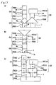
- the combination shown in Figs. 12 and 14a will be explained in comparison with other combinations.
- the combination of the first piece P1 and the second piece P2 according to the present invention is implemented by a long square shaft block 1A placed over a triangle block 4.
- the triangle block 4 receives an inclined load, the combination will fall down from the joint Jg but not the base because the width WG of the groove G is smaller than the width WS of the flat plane S.
- a first piece 1' has the width WS' of a flat plane S arranged equal to the width WG of a groove and its combination will fall down from the joint Jf" with the flat plane S in a known manner.
- Fig. 14c illustrates a combination where a trapezoid block 4' arranged by truncating a triangle and having a small side Sm at the top is used for allowing the combination to fall down from an intentionally narrowed joint.
- the weight of a long square shaft block 1A acts on the narrow joint Jf' causing the trapezoid block 4' to drop down.
- the combination is highly unstable, it will create no fun. With no use of the grooves, the centering of the blocks becomes troublesome thus making the building up of the blocks difficult.
- the triangle block 4 and the trapezoid block 4' shown in Figs. 14a, 14b, and 14c are slightly tiltedunder the same condition, the combinations shown in Figs. 14b and 14c will fall down from the joints Jf' and Jf" quicker than the combination shown in Fig. 14a .
- Fig. 15 is an enlarged view of the second piece P2 tilted relative to the first piece P1, showing a periphery of the groove.
- the second piece P2 When the second piece P2 is tilted relative to the first piece P1, its portion directly facing the corner edge L1 of the first piece P1 is shifted by a distance d1 to the location L2 or the corner edge A of the second piece P2 is moved by a distance d2 from the bottom Gb of the groove.
- a frictional resistance will however be developed. This prevents the corner edge A of the triangle block 4 from moving out from the groove G.
- the center line of the block is tilted at an angle M from the center of the groove G as the corner edge A moves.
- the present invention permits the tilting of the block against the horizontal to be favorably compensated by the functional movement of the joint Jg.
- Fig. 14d illustrates a functional model of the compensating movement for ease of theoretical understanding of the advantageous combination shown in Fig. 14a .
- the j oint Jg is expressed by a V symbol while the joint Jf with the flat plane S is denoted by the circle and the direction of the groove is denoted by OL1.
- the floor 0 is a member of the functional movement and thus applied as a base piece P0.
- the base piece P0 may be replaced by any other building block.
- a group or first set G1 of the floor 0, the cube block 1, and the triangle block 4 are referred to as a unit of the combination.
- both the first piece P1 and the second piece P2 are cube blocks.
- the flat plane S on the first piece P1 is supported by the bottom side 41 of the triangle block 4 serving as the base piece P0, the second piece P2 can be held in stableness.
- the triangle block 4 and the two cube blocks 1 constitute a second set G2 which is a reverse of the first set G1, showing the unit of the combination.
- Fig. 17 illustrates more intricate examples of the combination.
- a fifth group G5 is placed upside down.
- the third group G3 is differentiated from the fourth group G4 by the fact that the direction of the groove is different between OL1 and OL2, showing variations.
- Fig. 18a illustrates a fundamental shape B of the first piece P1.
- the groove width WG is coincided at the center line CL with the width WS of the flat plane S.
- the fundamental shape B may be modified to such a cubic shape 1 as shown in Fig. 18b or such a doughnut half shape 3 as shown in Fig. 18c .
- the cube block 1 has a top side 12 thereof margined for engagement with a triangle block 4 at the intermediate. The top side 12 of the cube block 1 can thus be utilized at optimum.
- both the sides at the corner edge may be arranged to come substantially in face contact with the groove.
- the other side at the corner edge may be arranged of a cylindrical plane to come substantially in linear contact with the groove.
- the ridge line Ab along the corner edge at each end of the flat plane may extend parallel with the lengthwise bottom Gb of the groove. This allows the engagement of the second piece P2 with the groove G to be implemented with the blocks tilted as shown in Fig. 10c , thus ensuring to build up a unique structure with balance.
- the second piece may have the flat plane and the groove. This allows the first piece P1 to serve as the second piece P2 fitted into the groove, as shown in Fig. 10b .
- another small triangle block 4A can be fitted into the groove G of the long square shaft block 1A which has engaged with the grooves G of the two doughnut half blocks 3, thus permitting a less number of the blocks to build up a more intricate structure of the combination.
- the first piece may be arranged of fundamentally a cubic shape, a rectangular parallelepiped shape, and/or a cylindrical shape. This allows any conventional building block of a typical shape to be provided with a groove G, such as shown in Fig. 2 or 3 , and thus combined with the second piece P2, this building up a structure of the combination different from that of the prior art.
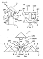
- the second piece may be arranged of fundamentally a right-angle isosceles shape. This allows every corner edge at the right angle to be engaged with the groove, whereby an inverted form of the combination can be implemented as is hardly feasible in the prior art, as shown in Fig. 1a.
- the building blocks according to the present invention are unelaborate and inexpensive in the fabricating process where the first piece is provided simply with a groove. Their advantages are as follows:
- the combination of the building blocks can produce an apparently contradictory effect or feature where its structure appears visually attractive, unique, and fragile and when loaded, becomes stable, thus improving the performance as a play toy or a decorative object.
- the building blocks are provided with the grooves, they can be used as conventional blocks while ensuring the above described novel advantages.
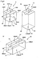
- a set of building blocks according to the present invention are stored in a box 100 which is equal in the thickness to the blocks, as shown in Fig. 1 .
- the building blocks are arranged of such shapes as shown in Figs. 2 to 7 .
- the blocks are substantially equal in the thickness and their dimensional radio of the vertical to the horizontal is as uniform as 1: 2. It is then assumed in this embodiment that the unit dimension is 35 mm and its doubled dimension is 70 mm.
- the building blocks include a first piece P1 having a groove G, which will be described later in more detail, and a second piece P2 arranged to be accepted by the groove G, as best shown in Fig. 12 .
- the two pieces are simply relative to each other.
- the first piece P1 provided with the groove G may serve as the second piece P2 in the combination as shown in Fig. 13a.
- the two pieces P1 and P2 are placed one over the other, starting from the floor 0.
- a cube block 1 has each side thereof sized by the square of the unit dimension, including a bottom side 11 having a flat plane S and a top side 12 which extends parallel with the bottom side 11 and has a V-shaped groove 13 scored substantially across the center thereof.
- the top and bottom sides are parallel and identical in the shape. Accordingly, as the groove 13 is provided in substantially the center of the top side 12, the center of the width WS of the planer surface S of the bottom side 11 and the center of the width WG of the groove 13 are coincided with each other at the reference plane H. This can be equal to the other blocks of which the top and bottom sides are identical in the size.
- a right-angled linear corner edge A1 is defined between any adjacent two of the bottom side 11, the top side 12, the two lateral sides 14; 14, and the two, front and rear, sides 15, 15. Also, the bottom Gb of the groove 13 extends parallel with the ridge line Ab along the right-angled linear corner edge A1 between the bottom side 11 and the lateral side 14.
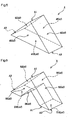
- Fig. 5 illustrates a triangle block 4 arranged of a triangular prism shape comprising a bottom side 41 having a flat plane S, two sloping sides 42, 42 having a flat plane Af, and two, front and rear, sides 45, 45 having a flat plane Af which extend parallel with each other and are of a right isosceles shape having two equal side lines along the sloping sides 42, 42.
- Each of the two equal side lines of the right isosceles shape of the two, front and rear, sides 45, 45 is equal to two times the unit dimension while the thickness or distance between the two sides 45, 45 is equal to the unit dimension.
- a triangular corner edge A3 is defined between the bottom side 41 and the sloping side 42 intersectingat 45 degrees while a right-angled linear corner edge A1 is defined between the two sloping sides 42, 42.
- the cube block 1 and the triangle block 4 can be assembled in such a combination as shown in Fig. 12 where the groove G of the cube block1 accepts the right-angled linear corner edge A1 of the triangle block 4.
- the cube block 1 serves as the first piece P1 and the triangle block 4 serves as the second piece P2.
- the groove G in the cube block 1 is defined by the groove bottom Gb and two groove surfaces Ga.
- the groove surfaces Ga are symmetrically tilted at substantially 45 degrees of the tilting angle C1 from the reference plane H orthogonal to the flat plane S.
- the groove bottom Gb extends parallel with the ridge line Ab along the right-angled linear corner edge between the two flat planes S as is disposed at which the two groove surfaces Ga intersect each other at substantially 90 degrees of the groove angle C2. It is now noted that the depth of the groove G is 6 mm orthogonally from the top side as will be identical to that of each groove.
- the groove G accepts the right-angled linear corner edge A1 of the triangle block 4
- its two surfaces Ga come into face contact with the two flat planes Af which define the right-angled linear corner edge A1 therebetween. Since the weight of the triangle block 4 is uniformly received by the two groove surfaces Ga, the blocks can be built up with balance.
- Fig. 2a illustrates a long square shaft block 1A arranged of a vertically extending parallelepiped shape which is two times greater in the height than the cube block 1, including a bottom side 11A and a top side 12A which are identical to the bottom side 11 and the top side 12 of the cube block 1.
- a groove 13A identical in the shape to the groove 13 is provided in substantially the center of the top side 12A to extend from the front side to the rear side. While each of the bottom side 11A and the top side 12A is sized by the square of the unit dimension; the height of the block 1A is equal to two times the unit dimension.
- Fig. 2c illustrates a wide square shaft block 1B arranged of a thicknesswisely extending parallelepiped shape which is two times greater in the thickness along the groove bottom Gb than the cube block 1, including a bottom side 11B, a top side 12B, and two, front and rear, sides 15B, 15B which are identical to the two, front and rear, sides 15, 15 of the cube block 1.
- a groove 13B identical in the shape to the groove 13 is provided in substantially the center of the top side 12B to extend in the thicknesswise direction. While the distance between the bottom side 11B and the top side 12B is equal to the unit dimension, the length of the groove Gb as the thickness of the block is equal to two times the unit dimension.
- a right-angled linear corner edge A1 is defined between any two adjacent sides of either the long square shaft block 1A or the wide square shaft 1B.
- the ridge line Ab along the right-angled linear corner edge between the bottom side 11A or 11B and the lateral side extends parallel with the groove bottom Gb. Also, any two opposite planes Af are parallel with each other.
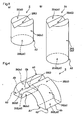
- Fig. 3a illustrates a cylinder block 2 arranged of a cylindrical shape including a bottom side 21 having a flat plane S, a top side 22 arranged in parallel with the bottom side 21, and a lateral side 24 having a cylindrical plane Ar.
- a groove 23 is scored along the diameter in the top side 22.
- the height and the diameter of the bottom side 21 and the top side 22 are equal to the unit dimension.
- a circular corner edge A2 at a right angle is defined between the flat plane Af and the cylindrical plane Ar.
- Fig. 4 illustrates a doughnut half block 3 arranged of a semi-circular cylindrical shape including a bottom side 31 having a flat plane S, a top side 34 having an arcuate plane Ar, and two, front and rear, sides 35, 35 having a fan-shaped flat plane Af and arranged in parallel with each other.
- a groove 33 is scored along the axial direction in the uppermost end of the top side 34.
- the bottom side 31 has a recess 36 of a semi-circular cylindrical shape provided axially in the center along the widthwise direction thereof.
- the thickness along the length of the groove Gb and the diameter of the notch 36 are equal to the unit dimension.
- the width of the bottom side 31 is equal to the unit dimension.
- the cylinder block 2 and the doughnut half block 3 may be assembled together as shown in Fig. 13a.
- the doughnut half block 3 serves as the first piece P1 while the cylinder block 2 serves as the second piece P2.
- the groove G in the doughnut half block 3 is identical in the construction to the groove G in the cube block 1 and is arranged in which its side surfaces Ga are symmetrically tilted at substantially 45 degrees of the tilting angle C1 from the reference plane H orthogonal to the flat plane S.
- the two surfaces Ga intersect each other at substantially 90 degrees of the groove angle C2 along the bottom Gb of the groove G and the ridge line Ab along the right-angled linear corner edge adjacent to the flat plane S extends parallel with the flat plane S.
- the groove G accepts the circular corner edge A2 of the cylinder block 2
- its surface Ga comes into face contact with the flat plane Af which is defined by the circular corner edge A2.
- the cylindrical plane Ar defined between the two circular corner edges A2 comes into linear contact with the groove surface Ga. Since the weight of the cylinder block 2 is uniformly received by the groove surface Ga at the face contact and the other groove surface Ga at the linear contact, the blocks can be built up with balance.
- Fig. 3b illustrates a long cylinder block 2A arranged of a vertically extending cylindrical shape which is two times greater in the height than the cylinder block 2, including a bottom side 21A and a top side 22A which are identical to the bottom side 21 and the top side 22 of the cylinder block 2, and a lateral side 24 having a cylindrical plane Af.
- a groove 23A identical in the shape to the groove 23 is scored along the diameter in substantially the center of the top side 22A.
- a circular corner edge A2 at a right angle is defined between the flat planeAf and the cylindrical plane Ar.
- the height of the block 2A is equal to two times the unit dimension.
- Fig. 6 illustrates a recessed triangle block 5 arranged substantially identical in the shape and size to the triangle block 4, including a bottom side 51 having a flat plane S and two, front and rear, sides 55, 55 having a flat plane Af which extend parallel with each other and are of a right isosceles shape having two equal side lines defined by two sloping sides 52, 52 of flat plane Af.
- a recess 56 is provided in the center of the bottom side 51 extending thicknesswisely between the two, front and rear, sides 55, 55.
- the recess 56 is arranged of a right isosceles shape in the cross section for accepting the right-angled linear corner edge of any other block.
- the width of the recess 56 is equal to the unit dimension while each of the two sloping side lines of the recess 56 extends 36 mm.
- a triangular corner edge A3 is defined between the bottom side 51 and the sloping side 52 which intersect each other at 45 degrees while a right-angled linear corner edge A1 between the two sloping sides 52, 52 extends from the front side 55 to the rear side 55.
- Fig. 7 illustrates a doughnut block 6 arranged of a hollow cylindrical shape, including a bottom side 61 having a flat plane S, a top side 62 arranged parallel with the bottom side 61, and a lateral side 64 having a circular plane Ar.
- the doughnut block 6 has a through hole 66 provided axially in the center thereof. Two grooves 63, 63 are provided along the diameter in the top side 62 as intersect each other.
- the diameter of the bottom side 61 and the top side 62 is equal to two times the unit dimension while the height of the block 6 is equal to the unit dimension.
- the through hole 66 generously accepts the cylinder block 2 or the long cylinder block 2A.
- a circular corner edge A2 at the right angle is defined between the flat plane Af and the circular plane Ar.
- a small triangle block 4A is similar in the shape to the triangle block 4 as its scale ratio to the triangle block 4 is 1:2.
- the middle triangle block 4B is a right isosceles identical to substantially a half of the triangle block 4 provided by dividing vertically along the center line from the right angle vertex.
- the arrow block 7 has such a shape that a right isosceles equal to the small triangle block 4A is reduced at the linear corner edge A1 from the triangle block 4.
- the cylinder half block 8 is equal to substantially a half of the cylinder block 2 provided by dividing vertically along the center line.
- the triangle block 4 and the small triangle block 4A can serve as the second piece P2.
- the other blocks 4B, 7, and 8 can serve as either the first P1 or second piece P2.
- Fig. 8 illustrates an example of the combination where the wide square shaft block 1B is placed on the horizontal plane of a desk or the like and its groove 13B receives at the front half the linear corner edge A1 of the cube block 1 and at the rear half the right-angled corner edge A1 of the triangle block 4.
- the wide square shaft block 1B serves as the first piece P1 while the cube block 1 and the triangle block 4 serve as the second pieces P2.
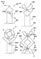
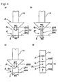
- Fig. 9a illustrates another example of the combination where the long square shaft block 1A serves as the first piece P1 and accepts at its groove 13A the linear corner edge A1 of the cube block 1 serving as the second piece P2. While the cube block 1 is tilted at 45 degrees, its linear corner edge A1' coming opposite to the linear corner edge A1 accepted in the groove 13A is the uppermost point.
- Fig. 9b illustrates a modification of the combination shown in Fig. 9a where the doughnut half block 3 serving as the first piece P1 is engaged at its groove 33 with the linear corner edge A1' of the cube block 1.
- 9c illustrates a further example of the combination where the long square shaft block 1A serving as the first piece P1 is engaged at its groove 13A with the linear corner edge A1 of the recessed triangle block 5 serving as the second piece P2 while the recess 56 of the recessed triangle block 5 receives the doughnut block 6, making a balance.
- Fig. 9d illustrates a further example of the combination starting with two of the recessed triangle blocks 5, 5 joined to each other thus to develop substantially 90 degrees of the corner at each abutment of the triangle corner edges A3, A3 and serve in a pair as the second piece P2.
- the abutment corner is then received by the groove 33 of the doughnut half block 3 placed on the horizontal plane S7 as serving as the first piece P1.
- Another doughnut half block 3 is placed over the opposite abutment corner at 90 degrees of the two recessed triangle blocks 5, 5 remaining balanced.
- the groove G of each doughnut half block 3 allows the two recessed triangle blocks 5, 5 to be closely held together and joined to each other.
- the two recessed triangle blocks 5, 5 may be engaged at their linear corner edges A1, A1 with the groove 33 of the doughnut half block 3.
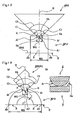
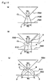
- Fig. 10a illustrates a still further example of the combination where the long square shaft block 1A serving as the second piece P2 is placed on the horizontal plane S7 and engaged at both the linear corner edges A1, A1 of its top side 12A with the grooves 33, 33 of the two doughnut half blocks 3, 3 respectively serving as the first pieces P1.
- the recessed triangle block 5 is placed on the two doughnut half block 3 with both the linear corner edges A1, A1 of its top side remaining engaged with the corresponding grooves 33, 33 so that its inner side at its recess 56 comes into face contact with the bottom sides 31, 31 of both the doughnut half blocks 3, 3. Since any stress for disengaging the doughnut half blocks 3, 3 from the corresponding linear corner edges A1, A1 is symmetrically relieved by the inner side at the recess 56 of the recessed triangle block 5, the blocks can be built up with balance.
- Fig. 10b illustrates a still further example of the combination starting the doughnut half block 3 placed in an inverted form on the horizontal plane S'. More specifically, the doughnut half block 3 is supported on the plane S' at a pair of supporting lines F, each defined between the top side 34 and the groove surface Ga. Two of the cube blocks 1, 1 are placed symmetrically at the left and the right on the bottom side 31 of the doughnut half block 3. Then, two of the small triangle blocks 4A, 4A are placed in the groove engagement on the corresponding cube blocks 1, 1. Since the weight of the cube blocks 1, 1 and the small triangle blocks 4A, 4A is uniformly received by the two supporting lines F, F, the combination f the blocks can be balanced between the right and the left. In this example, the cube blocks 1, 1 serve as the first pieces P1 while the small triangle blocks 4A, 4A serve as the second pieces P2.
- Fig. 10c illustrates a still further example of the combination where two of the triangle blocks 4, 4 are place on the horizontal plane S' and their sloping sides 42, 42 support the doughnut half blocks 3, 3 respectively serving as the first pieces P1.
- the long square shaft block 1A serving as the second piece P2 is engaged at both the linear corner edges A1, A1 of its bottom side 11A with the grooves 33, 33 of the two doughnut half blocks 3, 3.
- the small triangle block 4A serving as the first piece P1 is placed on the long square shaft block 1A and another triangle block 4 is finally placed on the small triangle block 4A.
- the two opposite lateral sides 14A, 14A of the long square shaft block 1A along the linear corner edges A1, A1 are parallel with as accepted in the corresponding grooves 33, 33 of the doughnut half blocks 3, 3 while the bottom side 11A extends parallel with the horizontal plane S'.
- the two small triangle blocks 4, 4 are removed from the corresponding doughnut half blocks 3,3, the remaining blocks can securely be held in a building from but not separated from one another.
- the surface Ga at one side of each groove 33 extending parallel with the horizontal plane S' are loaded with the weight of the blocks 1A, 4A, and 4 while the other surface Ga of each groove 33 receives a lateral stress from the doughnut half block 3.
- the lateral stresses against the groove surfaces Ga, Ga are urged from both sides, they are offset to make a balance. All the weight is supported along the support line F between the bottom side 31 and the top side 34 of the doughnut half block 3 at either side.
- Fig. 11 illustrates a still further example of the combination where two of the long square shaft blocks 1A, 1A are spaced by a distance from each other and engaged with the corresponding cylinder blocks 2, 2 at the upper.
- the two corresponding surfaces Ga, Ga of the grooves in the two cylinder blocks 2, 2 are parallel with each other while the other two surfaces Ga, Ga extend parallel with the horizontal plane S'.
- the two surfaces Ga, Ga of the grooves extending parallel with the horizontal plane S' then support directly the two triangle corner edges A3 of the triangle block 4.
- the doughnut half block 3 is placed on the linear corner edge A1 of the doughnut half block 3.
- each cylinder block 2 having the flat plane Af stays in face contact with the surface Ga of the groove in the corresponding long square shaft block 1A while the lateral side 24 having the circular plane Ar is in linear contact with the other surface Ga of the same.
- the blocks can be balanced and built up to develop a desired bcorner edge form.
- the two long square shaft blocks 1A, 1A and the doughnut half blocks 3 serve as the first pieces P1 while the cylinder blocks 2, 2 and the triangle block 4 serve as the second pieces P2.
- the unit dimension described in the foregoing embodiment of the building blocks is not limited to 35 mm or 70 mm but may arbitrarily be determined as desired. More specifically, 35 mm is the unit dimension while 70 mm is two times the unit dimension in the embodiment.
- the blocks may be fabricated from any other applicable material than wood, such as plastic resin, cork, or sponge, which can provide a favorable degree of physical strength particularly at the grooves.
- the blocks are classified into two types, the first piece P1 and the second piece P2.
- the combination between the first piece P1 and the second piece P2 having at least one corner edge is not limitative but maybe implemented by any other modification with balance. It is at least conditioned that the engagement between a groove and a corner edge is involved while the pattern of building form is indefinite.
- the foregoing embodiment defines that the depth of the groove is 6 mm and the width WG of the groove is 1/3 the unit dimension.
- the depth of the groove is not limited to 6 mm.
- the blocks in a building form may be balanced with ease when the width (or depth) of the groove is greater or with difficulty when the same is smaller.
- the size can be determined depending on the use and purpose under the principle shown in Fig. 15a .
- the building blocks are assembled in such a combination as shown in Fig. 12 .
- the combination is not limited to that shown in Fig. 12 .
- the first piece P1 and the second piece P2 may arbitrarily be determined in the number and type.
- the second piece P2 with no groove may be implemented by a block which is arranged identical in the shape to the cube block 1 but having no groove.
- the ratio between two dimensions for the blocks is 1:2 as bound by the definition.
- the ratio may be 1: 3 or any combination of integral numerals if desired.
- the ratio of 1:0.5 may also be feasible.
- the shape at the groove bottom Gb and the corner edge line Ab is arranged at substantially a right angle in the foregoing embodiment, it may be rounded so long as the engagement between the groove and the corner edge remains favorable.
- the building blocks according to the present invention is favorably used as a children's playing toy and applicable to any action for preventing from senile dementia or rehabilitating the fingers of a disabled person. Also, the building blocks can freely be assembled to build up a decorative object.
Landscapes
- Engineering & Computer Science (AREA)
- Multimedia (AREA)
- Toys (AREA)
Applications Claiming Priority (5)
| Application Number | Priority Date | Filing Date | Title |
|---|---|---|---|
| JP2003000568U | 2003-02-07 | ||
| JP2003000568U JP3097963U (ja) | 2003-02-07 | 2003-02-07 | 積み木セット |
| JP2003309198 | 2003-09-01 | ||
| JP2003309198A JP3762766B2 (ja) | 2003-02-07 | 2003-09-01 | 積み木セット |
| PCT/JP2004/001285 WO2004069363A1 (ja) | 2003-02-07 | 2004-02-06 | 積み木 |
Publications (3)
| Publication Number | Publication Date |
|---|---|
| EP1593416A1 EP1593416A1 (en) | 2005-11-09 |
| EP1593416A4 EP1593416A4 (en) | 2008-03-05 |
| EP1593416B1 true EP1593416B1 (en) | 2013-04-10 |
Family
ID=32852640
Family Applications (1)
| Application Number | Title | Priority Date | Filing Date |
|---|---|---|---|
| EP04708873.7A Expired - Lifetime EP1593416B1 (en) | 2003-02-07 | 2004-02-06 | Set of building blocks |
Country Status (4)
| Country | Link |
|---|---|
| US (1) | US8449345B2 (ja) |
| EP (1) | EP1593416B1 (ja) |
| JP (1) | JP3762766B2 (ja) |
| WO (1) | WO2004069363A1 (ja) |
Families Citing this family (2)
| Publication number | Priority date | Publication date | Assignee | Title |
|---|---|---|---|---|
| WO2009060637A1 (ja) * | 2007-11-07 | 2009-05-14 | Inoue, Akira | ムーブ積木 |
| CN106869393A (zh) * | 2017-02-25 | 2017-06-20 | 宁波市若水助创商务咨询服务有限公司 | 一种相互插接咬合连接块 |
Family Cites Families (12)
| Publication number | Priority date | Publication date | Assignee | Title |
|---|---|---|---|---|
| FR956536A (ja) * | 1950-02-02 | |||
| US2132757A (en) * | 1936-10-08 | 1938-10-11 | Halsam Products Company | Toy building block |
| US2440836A (en) * | 1946-03-18 | 1948-05-04 | Oscar E Turngren | Building construction and units |
| FR1015385A (fr) * | 1947-04-05 | 1952-09-16 | Jeu de construction | |
| US3303604A (en) * | 1963-12-11 | 1967-02-14 | Robert G Mote | Building toy |
| US3660928A (en) * | 1970-08-28 | 1972-05-09 | Jorge Picazo Michel | Modular building blocks with interfitting grooved surfaces |
| US3863918A (en) * | 1973-12-10 | 1975-02-04 | George A Kramer | Building block game |
| US4197669A (en) * | 1977-08-01 | 1980-04-15 | Hynes Bernard D | Construction elements and assembled structures |
| US4372076A (en) * | 1979-06-18 | 1983-02-08 | Harald Beck | Modular interlocking block construction toy |
| JPH084662B2 (ja) * | 1987-01-12 | 1996-01-24 | 明 磯 | デスク積み木 |
| US5938496A (en) * | 1996-04-16 | 1999-08-17 | Patent Category Corp. | Constructional pieces with deformable joints |
| JPH11319333A (ja) | 1998-05-15 | 1999-11-24 | Tsutomu Yamana | 積木玩具 |
-
2003
- 2003-09-01 JP JP2003309198A patent/JP3762766B2/ja not_active Expired - Fee Related
-
2004
- 2004-02-06 EP EP04708873.7A patent/EP1593416B1/en not_active Expired - Lifetime
- 2004-02-06 WO PCT/JP2004/001285 patent/WO2004069363A1/ja active Application Filing
- 2004-02-06 US US10/544,721 patent/US8449345B2/en active Active
Also Published As
| Publication number | Publication date |
|---|---|
| WO2004069363A1 (ja) | 2004-08-19 |
| US20070000203A1 (en) | 2007-01-04 |
| JP2004255162A (ja) | 2004-09-16 |
| US8449345B2 (en) | 2013-05-28 |
| JP3762766B2 (ja) | 2006-04-05 |
| EP1593416A1 (en) | 2005-11-09 |
| EP1593416A4 (en) | 2008-03-05 |
Similar Documents
| Publication | Publication Date | Title |
|---|---|---|
| US20020078653A1 (en) | Card like construction element | |
| WO1995012443A1 (en) | Three-dimensional puzzle | |
| US11110368B2 (en) | Structural element | |
| US4633639A (en) | Construction block | |
| EP1593416B1 (en) | Set of building blocks | |
| US6655685B2 (en) | Three-dimensional jigsaw puzzle | |
| JPH049435B2 (ja) | ||
| CA1041763A (en) | Educational, structural, ornamental or toy block | |
| EP2024047B1 (en) | Improvement in interlocking toy bricks | |
| US11358071B1 (en) | Building block toy | |
| CN211836313U (zh) | 拼接积木组件及拼接结构 | |
| US20100178838A1 (en) | Toy Brick Structure | |
| US20100032897A1 (en) | Three dimensional puzzle | |
| US6443798B1 (en) | Building block toy set | |
| KR20070000067U (ko) | 조립 블럭 | |
| CA2287694A1 (en) | Vertical and horizontal belt masonry system | |
| JPH069206Y2 (ja) | 建築用板 | |
| JP3239368U (ja) | 箱状立体パズル | |
| JP2007181588A (ja) | ブロック玩具。 | |
| WO1990009492A1 (en) | Autofitting building blocks and bricks | |
| KR102666240B1 (ko) | 다빈치 브릿지 완구 조립 세트 | |
| JP5060346B2 (ja) | 出隅部材及びその製造方法 | |
| EP3560568B1 (en) | Assembly blocks | |
| KR200174448Y1 (ko) | 놀이용 블록세트 | |
| JP2022063505A (ja) | ブロックおもちゃ |
Legal Events
| Date | Code | Title | Description |
|---|---|---|---|
| PUAI | Public reference made under article 153(3) epc to a published international application that has entered the european phase |
Free format text: ORIGINAL CODE: 0009012 |
|
| 17P | Request for examination filed |
Effective date: 20050801 |
|
| AK | Designated contracting states |
Kind code of ref document: A1 Designated state(s): AT BE BG CH CY CZ DE DK EE ES FI FR GB GR HU IE IT LI LU MC NL PT RO SE SI SK TR |
|
| AX | Request for extension of the european patent |
Extension state: AL LT LV MK |
|
| DAX | Request for extension of the european patent (deleted) | ||
| A4 | Supplementary search report drawn up and despatched |
Effective date: 20080201 |
|
| RIC1 | Information provided on ipc code assigned before grant |
Ipc: A63F 9/12 20060101ALN20080128BHEP Ipc: A63F 9/26 20060101ALI20080128BHEP Ipc: A63H 33/08 20060101AFI20040826BHEP Ipc: A63F 9/00 20060101ALN20080128BHEP |
|
| 17Q | First examination report despatched |
Effective date: 20100518 |
|
| GRAP | Despatch of communication of intention to grant a patent |
Free format text: ORIGINAL CODE: EPIDOSNIGR1 |
|
| GRAS | Grant fee paid |
Free format text: ORIGINAL CODE: EPIDOSNIGR3 |
|
| GRAL | Information related to payment of fee for publishing/printing deleted |
Free format text: ORIGINAL CODE: EPIDOSDIGR3 |
|
| GRAS | Grant fee paid |
Free format text: ORIGINAL CODE: EPIDOSNIGR3 |
|
| GRAA | (expected) grant |
Free format text: ORIGINAL CODE: 0009210 |
|
| AK | Designated contracting states |
Kind code of ref document: B1 Designated state(s): AT BE BG CH CY CZ DE DK EE ES FI FR GB GR HU IE IT LI LU MC NL PT RO SE SI SK TR |
|
| REG | Reference to a national code |
Ref country code: GB Ref legal event code: FG4D |
|
| REG | Reference to a national code |
Ref country code: CH Ref legal event code: EP Ref country code: AT Ref legal event code: REF Ref document number: 605659 Country of ref document: AT Kind code of ref document: T Effective date: 20130415 |
|
| REG | Reference to a national code |
Ref country code: IE Ref legal event code: FG4D |
|
| REG | Reference to a national code |
Ref country code: DE Ref legal event code: R096 Ref document number: 602004041661 Country of ref document: DE Effective date: 20130606 |
|
| PG25 | Lapsed in a contracting state [announced via postgrant information from national office to epo] |
Ref country code: SI Free format text: LAPSE BECAUSE OF FAILURE TO SUBMIT A TRANSLATION OF THE DESCRIPTION OR TO PAY THE FEE WITHIN THE PRESCRIBED TIME-LIMIT Effective date: 20130410 |
|
| REG | Reference to a national code |
Ref country code: AT Ref legal event code: MK05 Ref document number: 605659 Country of ref document: AT Kind code of ref document: T Effective date: 20130410 |
|
| REG | Reference to a national code |
Ref country code: NL Ref legal event code: VDEP Effective date: 20130410 |
|
| PG25 | Lapsed in a contracting state [announced via postgrant information from national office to epo] |
Ref country code: GR Free format text: LAPSE BECAUSE OF FAILURE TO SUBMIT A TRANSLATION OF THE DESCRIPTION OR TO PAY THE FEE WITHIN THE PRESCRIBED TIME-LIMIT Effective date: 20130711 Ref country code: ES Free format text: LAPSE BECAUSE OF FAILURE TO SUBMIT A TRANSLATION OF THE DESCRIPTION OR TO PAY THE FEE WITHIN THE PRESCRIBED TIME-LIMIT Effective date: 20130721 Ref country code: AT Free format text: LAPSE BECAUSE OF FAILURE TO SUBMIT A TRANSLATION OF THE DESCRIPTION OR TO PAY THE FEE WITHIN THE PRESCRIBED TIME-LIMIT Effective date: 20130410 Ref country code: NL Free format text: LAPSE BECAUSE OF FAILURE TO SUBMIT A TRANSLATION OF THE DESCRIPTION OR TO PAY THE FEE WITHIN THE PRESCRIBED TIME-LIMIT Effective date: 20130410 Ref country code: SE Free format text: LAPSE BECAUSE OF FAILURE TO SUBMIT A TRANSLATION OF THE DESCRIPTION OR TO PAY THE FEE WITHIN THE PRESCRIBED TIME-LIMIT Effective date: 20130410 Ref country code: PT Free format text: LAPSE BECAUSE OF FAILURE TO SUBMIT A TRANSLATION OF THE DESCRIPTION OR TO PAY THE FEE WITHIN THE PRESCRIBED TIME-LIMIT Effective date: 20130812 Ref country code: BE Free format text: LAPSE BECAUSE OF FAILURE TO SUBMIT A TRANSLATION OF THE DESCRIPTION OR TO PAY THE FEE WITHIN THE PRESCRIBED TIME-LIMIT Effective date: 20130410 Ref country code: FI Free format text: LAPSE BECAUSE OF FAILURE TO SUBMIT A TRANSLATION OF THE DESCRIPTION OR TO PAY THE FEE WITHIN THE PRESCRIBED TIME-LIMIT Effective date: 20130410 |
|
| PG25 | Lapsed in a contracting state [announced via postgrant information from national office to epo] |
Ref country code: CY Free format text: LAPSE BECAUSE OF FAILURE TO SUBMIT A TRANSLATION OF THE DESCRIPTION OR TO PAY THE FEE WITHIN THE PRESCRIBED TIME-LIMIT Effective date: 20130410 Ref country code: BG Free format text: LAPSE BECAUSE OF FAILURE TO SUBMIT A TRANSLATION OF THE DESCRIPTION OR TO PAY THE FEE WITHIN THE PRESCRIBED TIME-LIMIT Effective date: 20130710 |
|
| PG25 | Lapsed in a contracting state [announced via postgrant information from national office to epo] |
Ref country code: DK Free format text: LAPSE BECAUSE OF FAILURE TO SUBMIT A TRANSLATION OF THE DESCRIPTION OR TO PAY THE FEE WITHIN THE PRESCRIBED TIME-LIMIT Effective date: 20130410 Ref country code: CZ Free format text: LAPSE BECAUSE OF FAILURE TO SUBMIT A TRANSLATION OF THE DESCRIPTION OR TO PAY THE FEE WITHIN THE PRESCRIBED TIME-LIMIT Effective date: 20130410 Ref country code: EE Free format text: LAPSE BECAUSE OF FAILURE TO SUBMIT A TRANSLATION OF THE DESCRIPTION OR TO PAY THE FEE WITHIN THE PRESCRIBED TIME-LIMIT Effective date: 20130410 Ref country code: SK Free format text: LAPSE BECAUSE OF FAILURE TO SUBMIT A TRANSLATION OF THE DESCRIPTION OR TO PAY THE FEE WITHIN THE PRESCRIBED TIME-LIMIT Effective date: 20130410 |
|
| PLBE | No opposition filed within time limit |
Free format text: ORIGINAL CODE: 0009261 |
|
| STAA | Information on the status of an ep patent application or granted ep patent |
Free format text: STATUS: NO OPPOSITION FILED WITHIN TIME LIMIT |
|
| PG25 | Lapsed in a contracting state [announced via postgrant information from national office to epo] |
Ref country code: IT Free format text: LAPSE BECAUSE OF FAILURE TO SUBMIT A TRANSLATION OF THE DESCRIPTION OR TO PAY THE FEE WITHIN THE PRESCRIBED TIME-LIMIT Effective date: 20130410 Ref country code: RO Free format text: LAPSE BECAUSE OF FAILURE TO SUBMIT A TRANSLATION OF THE DESCRIPTION OR TO PAY THE FEE WITHIN THE PRESCRIBED TIME-LIMIT Effective date: 20130410 |
|
| 26N | No opposition filed |
Effective date: 20140113 |
|
| REG | Reference to a national code |
Ref country code: DE Ref legal event code: R097 Ref document number: 602004041661 Country of ref document: DE Effective date: 20140113 |
|
| PG25 | Lapsed in a contracting state [announced via postgrant information from national office to epo] |
Ref country code: MC Free format text: LAPSE BECAUSE OF FAILURE TO SUBMIT A TRANSLATION OF THE DESCRIPTION OR TO PAY THE FEE WITHIN THE PRESCRIBED TIME-LIMIT Effective date: 20130410 Ref country code: LU Free format text: LAPSE BECAUSE OF FAILURE TO SUBMIT A TRANSLATION OF THE DESCRIPTION OR TO PAY THE FEE WITHIN THE PRESCRIBED TIME-LIMIT Effective date: 20140206 |
|
| REG | Reference to a national code |
Ref country code: CH Ref legal event code: PL |
|
| PG25 | Lapsed in a contracting state [announced via postgrant information from national office to epo] |
Ref country code: LI Free format text: LAPSE BECAUSE OF NON-PAYMENT OF DUE FEES Effective date: 20140228 Ref country code: CH Free format text: LAPSE BECAUSE OF NON-PAYMENT OF DUE FEES Effective date: 20140228 |
|
| REG | Reference to a national code |
Ref country code: IE Ref legal event code: MM4A |
|
| PG25 | Lapsed in a contracting state [announced via postgrant information from national office to epo] |
Ref country code: IE Free format text: LAPSE BECAUSE OF NON-PAYMENT OF DUE FEES Effective date: 20140206 |
|
| REG | Reference to a national code |
Ref country code: FR Ref legal event code: PLFP Year of fee payment: 13 |
|
| PG25 | Lapsed in a contracting state [announced via postgrant information from national office to epo] |
Ref country code: TR Free format text: LAPSE BECAUSE OF FAILURE TO SUBMIT A TRANSLATION OF THE DESCRIPTION OR TO PAY THE FEE WITHIN THE PRESCRIBED TIME-LIMIT Effective date: 20130410 Ref country code: HU Free format text: LAPSE BECAUSE OF FAILURE TO SUBMIT A TRANSLATION OF THE DESCRIPTION OR TO PAY THE FEE WITHIN THE PRESCRIBED TIME-LIMIT; INVALID AB INITIO Effective date: 20040206 |
|
| REG | Reference to a national code |
Ref country code: FR Ref legal event code: PLFP Year of fee payment: 14 |
|
| REG | Reference to a national code |
Ref country code: FR Ref legal event code: PLFP Year of fee payment: 15 |
|
| PGFP | Annual fee paid to national office [announced via postgrant information from national office to epo] |
Ref country code: FR Payment date: 20230227 Year of fee payment: 20 |
|
| PGFP | Annual fee paid to national office [announced via postgrant information from national office to epo] |
Ref country code: GB Payment date: 20230227 Year of fee payment: 20 Ref country code: DE Payment date: 20230227 Year of fee payment: 20 |
|
| REG | Reference to a national code |
Ref country code: DE Ref legal event code: R071 Ref document number: 602004041661 Country of ref document: DE |
|
| REG | Reference to a national code |
Ref country code: GB Ref legal event code: PE20 Expiry date: 20240205 |
|
| PG25 | Lapsed in a contracting state [announced via postgrant information from national office to epo] |
Ref country code: GB Free format text: LAPSE BECAUSE OF EXPIRATION OF PROTECTION Effective date: 20240205 |