EP1591727B1 - Dichtungseinrichtung - Google Patents
Dichtungseinrichtung Download PDFInfo
- Publication number
- EP1591727B1 EP1591727B1 EP05008692A EP05008692A EP1591727B1 EP 1591727 B1 EP1591727 B1 EP 1591727B1 EP 05008692 A EP05008692 A EP 05008692A EP 05008692 A EP05008692 A EP 05008692A EP 1591727 B1 EP1591727 B1 EP 1591727B1
- Authority
- EP
- European Patent Office
- Prior art keywords
- sealing
- profile
- sealing profile
- section
- sealing device
- Prior art date
- Legal status (The legal status is an assumption and is not a legal conclusion. Google has not performed a legal analysis and makes no representation as to the accuracy of the status listed.)
- Expired - Lifetime
Links
Images


Classifications
-
- F—MECHANICAL ENGINEERING; LIGHTING; HEATING; WEAPONS; BLASTING
- F24—HEATING; RANGES; VENTILATING
- F24C—DOMESTIC STOVES OR RANGES ; DETAILS OF DOMESTIC STOVES OR RANGES, OF GENERAL APPLICATION
- F24C15/00—Details
- F24C15/02—Doors specially adapted for stoves or ranges
- F24C15/021—Doors specially adapted for stoves or ranges sealings for doors or transparent panel
Definitions
- the invention relates to a sealing device, preferably for the feed opening of a baking oven or oven, with at least one flexible sealing profile with two end sections, which runs essentially in a closed line, so that two substantially adjacent end sections form a joint, wherein the sealing device at least one corner - Includes or curved portion of a sealing profile, which has a stiffening element.
- Such a sealing device is used for example in the GB 2 106 974 A shown.
- a conventional sealing device usually consists of an elongated and mostly hollow sealing profile, forming or stiffening retaining means such as e.g. (round) corner hooks to adjust the sealing profile to the course of a baking muffle and to fix it on the oven side, a (straight) connector and silicone adhesive for sticking hook and connector.
- stiffening retaining means such as e.g. (round) corner hooks to adjust the sealing profile to the course of a baking muffle and to fix it on the oven side, a (straight) connector and silicone adhesive for sticking hook and connector.
- the prefabricated profile length is glued to the ring by means of the connector.
- the connector is a separate component which is glued into a lower profile chamber of the sealing profile.
- silicone adhesive By wetting the entire cut surface with silicone adhesive, a full-surface bonding of the cut surface to the seal joint is produced.
- the glued connector has the task to reinforce the joint in the sealing ring and secure against the tensile forces occurring at the sealing impact.
- Such a conventional sealing device comprises a plurality of individual components, which must be mounted individually in a plurality of work steps. This goes hand in hand with high material costs and high assembly costs.
- the invention is based on the object to simplify a sealing device of the type mentioned above and to facilitate the production
- the EP-A-277 098 discloses a sealing device, preferably for the feed opening of a baking oven or oven, with at least one flexible sealing profile with two end sections, which runs essentially in a closed line, so that two substantially adjacent end sections form a joint.
- the sealing device comprises at least one corner or curvature section of a sealing profile, which has a stiffening element, wherein the stiffening element has a curvature section with a substantially constant radius and wherein the stiffening element can bridge a joint to connect adjacent end sections.
- the stiffening element according to FIG. 3b is designed such that it has an extended leg, which adjoins the curved section.
- a shaping stiffening element bridges the joint of two substantially adjacent end sections of one or more sealing profiles in a corner or curvature section of the sealing device.
- the stiffening element which stiffens the curvature region of the sealing device, at the same time assumes the task of reinforcing the joint in the sealing ring and securing it against the tensile forces occurring at the sealing joint.
- the stiffening element simultaneously acts as a fastening device to attach a sealing profile to a component to be sealed.
- the sealing frame can thereby be taut and held in contact with the component to be sealed, which reduces leakage and increases the sealing efficiency of the sealing device according to the invention.
- a separate holding device can thereby be saved, which can further reduce the material requirement of the sealing device according to the invention.
- the sealing profile is at least partially hollow in cross-section. This increases the flexibility and improves the sealing effect of the sealing profile on the sealing surface. Moreover, the stiffening elements can then be arranged within the sealing profile, which significantly increases the connection between the stiffening elements and the sealing profile and significantly increases the maximum force transmission between the stiffening elements and the sealing profile. The joint is thus much more resilient.
- An improved sealing effect can be achieved if the sealing frame is adapted to the course of the baking oven muffle and essentially describes a polygon. Feed openings for the oven and stoves are normally substantially rectangular. A sealing device, which follows the course of the feed opening substantially in a closed line, has a plurality of straight sealing portions. Experience has shown that the leakages are smaller on a straight sealing section than on a curved sealing section.
- stiffening element In order to attach the stiffening element to the furnace, it proves to be advantageous if the stiffening element has a fastening device.
- a stiffening element fastened to the furnace clamps and stiffens the sealing profile and predetermines the course of the seal.
- the sealing profile is better held in contact with the component to be sealed.
- At least one stiffening element is a corner hook.
- corner hooks are adapted to hold the sealing frame firmly in door-side or furnace-side system and stabilize shaping. By using corner hooks, a particularly efficient sealing device can be realized.
- At least one stiffening element has a curvature section with a substantially constant radius.
- Curved stiffening elements are particularly suitable for stabilizing a sealing profile.
- At least one stiffening element has at least one extended leg following a curved section.
- non-curved portions of the sealing device are stabilized, which further improves the dimensional stability of the sealing frame in the areas next to the curved stiffening elements.
- the joint of two substantially adjacent end portions lies within the curvature portion of a stiffening element.
- the joint of two substantially adjacent end portions lies in the region of an extended leg of a stiffening element.
- the cut surfaces lie straight on one another and can be glued together better than if the cutting plane lies in the curvature region.
- stiffening elements are glued into the sealing frame.
- the stiffening elements are firmly connected to the sealing profile and a relative displacement of the sealing profile relative to the holding elements is no longer possible. This increases the dimensional stability of the sealing profile and contributes to increasing the sealing efficiency.
- sealing frame is glued to the cut surfaces of the joint with silicone adhesive to the closed profile.
- the sealing frame is attached to the hearth.
- the general structure of sealing devices is based on the in FIG. 1 illustrated sealer frame explained.
- the sealing device 1 consists of an elongated and at least partially hollow sealing profile 2, whose cross section in FIG. 3 will be shown.
- the sealing profile 2 is made of a high temperature resistant, elastic and flexible material, preferably extruded.
- different sealing profiles 2 made of different materials can be combined.
- the sealing frame produced from the successively arranged, partially hollow and elastic sealing profiles 2 is attached to a furnace in such a way that it surrounds the feed opening of the frying and baking tube of the oven in a closed line, and essentially follows the course of the feed opening.
- a sealing profile 2 used for the sealing device 1 according to the invention with reference to the FIGS. 1 to 3 described.
- Dimensional information such as upper, lower, left and right are only to be understood in relation to the view of the respective figure.
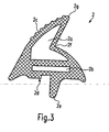
- FIG. 3 the cross-section of a sealing profile 2 used for the sealing device 1 according to the invention is shown.
- the sealing profile 2 has an approximately triangular cross-section and has an upper profile chamber 2a and a lower profile chamber 2b.
- the lower profile chamber 2b has a substantially rectangular cross-section and extends substantially parallel to the abutment side 2d of the sealing profile 2, with which the sealing profile 2 rests against the furnace to be sealed (not shown).
- a corresponding engagement device 2e is provided on the installation side, in order to secure the sealing profile 2 against slipping, and engages in a corresponding furnace-side arrangement, for example groove (not shown).
- the left upper leg of the sealing profile 2 forms the grooved sealing side (hereinafter also called sealing surface) 2c.
- the tip 2g in cross-section of the sealing profile connects the left, provided with the sealing surface 2c leg with the right, a bend 2f having leg of the sealing profile 2. If a pressure exerted by the sealing side on the sealing surface 2c, the right leg of the sealing profile bends. 2 at the kink 2f and the tip 2g lowers view down to the contact side 2d.
- the air contained in the upper profile chamber 2a can escape via a vent opening in the sealing profile 2.
- the feed opening of the roasting and baking tube of the oven (hereinafter also called baking muffle), in which a sealing device according to the invention is installed, has a rectangular shape with rounded corners.
- the dimensions of the loading opening are approx. 480 mm * 3150 mm.
- the sealing profile is prefabricated and has a total length of about 1496 mm, wherein the support side 2d is about 25 mm wide.
- the sealing profile 2 has planar cut surfaces, the cut planes extending substantially perpendicularly to the longitudinal direction of the sealing profile 2. For attachment of the corner hooks 3 on the sealing profile 2, the sealing profile 2 is opened on the support side.
- elongated slots or elongated holes 2h with a length of 20 mm +/- 3 mm are provided centrally on the sealing profile 2 on the support side 2d extending in the longitudinal direction of the sealing profile 2 and penetrate the material of the sealing profile 2 to the lower profile chamber 2b.
- the center of the first slot 2h 1 is spaced from a first end portion 2i 1 of the sealing profile 2 about 15 mm +/- 2 mm.
- the center of the second slot 2h 2 follows at a distance of 305 mm +/- 3 mm, that of the third slot 2h 3 at a distance of a further 433 mm +/- 4 mm and that of the fourth slot 2h 4 at a distance from another 315 mm +/- 4 mm.
- the center of the fourth slot 2h 4 from the other end portion 2i 2 of the sealing profile 2 about 428 mm +/- 4 mm apart.
- a vent hole 2j arranged with a diameter of about 2 mm, which penetrates the material of the sealing profile 2 to the upper profile chamber 2a.
- the vent hole 2j serves to discharge the displaced by closing the oven door from the upper profile chamber 2a air, so that the sealing profile 2 yields under the pressure exerted by the oven door pressure.
- the four corner hooks 3 are used for later attachment of the seal 2 in the stove and give the sealing profile 2 adapted to the baking muffle course.
- the corner hooks are made of a stiffer material than the sealing profile.
- the corner hooks 3 have a mounting portion 3b, which is attached to the furnace, from which - following the sealing course - on both sides parts of an arcuate engaging portion 3a extend.
- the engaging portion 3a engages in the assembled state via the openings 2h in the lower profile chamber 2b of the sealing profile 2 and is glued there using a silicone adhesive.
- the corner hooks 3 are fixed on the furnace side approximately in the corner points in which meet the edges of the feed opening of the furnace.
- the engagement portion 3a of a Eckhakens 3 is arcuately curved and serves for shaping stabilization of the sealing profile 2.
- the engagement portion 3a extends completely within the lower profile chamber 2b of the sealing profile 2, thus providing the curvature in the curved portion.
- the sealing profile describes a curve over an arc length of about 90 degrees with a constant radius of about 23.4 mm.
- the engagement section 3a extending in the lower profile chamber 2b of the sealing profile 2 also has a radius of approximately 23.4 mm over an arc length of approximately 90 degrees.
- the length of the engaging portion 3a is therefore about 36.8 mm.
- the slot opening 2h 1 is in the immediate vicinity of the end portion 2i 1 , bridges the arcuate curved engagement portion 3a of the corner hook 3 in the lower left corner over the joint and connects the two end portions 2i 1 and 2i 2 together.
- the engaging portion 3a extends out of the first, associated end portion 2i 1 of the sealing profile 2 into the second end portion 2i 2 of the sealing profile 2.
- the prefabricated profile length is glued to a closed frame in the area of the curvature.
- the end portions 2i 1 and 2i 2 of the sealing profile 2 adjacent and the cut surfaces are adjacent.
- corner hook 3 fulfills the task, which belongs to a connecting element in the prior art, namely to reinforce the joint in the sealing ring and to secure against the tensile forces occurring at the sealing joint, a connecting component is not absolutely necessary.
- the corner hook 3 is extended at the lower left edge of the picture on one side next to the curved portion, wherein the extended leg substantially parallel to the underside of the feed opening of the frying and baking tube extends the furnace.
- the extended portion 3c of the engagement portion 3a of the corner hook is not curved but straight and has a length of about 25 mm.
- the engagement portion 3a extends over its entire length in the lower profile chamber 2b of the sealing profile.
- the other three corner hooks 3 of the second example are identical to the corner hook of the first embodiment.
- the joint 4 is arranged in the region of the extended leg 3c.
- the cross section of the unprocessed sealing profile 2 in the second example is identical to the cross section of the unprocessed sealing profile 2 in the first embodiment.
- the sealing profile 2 of the second example differs from the sealing profile 2 of the first embodiment only in terms of the arrangement of the openings 2h 1 to 2h 4 for introducing the corner hooks 3 in relation to the end portions 2i 1 and 2i 2 of the sealing profile. 2
- the sealing profile must be prefabricated so that the end portions 2i 1 and 2i 2 meet at the predetermined location in the region of the extended leg.
- the sealing profile 2 is opened in the region of the curved sections.
- slots or slots in the support area 2d of the sealing profile 2 are attached.
- the center of the first slot 2h 1 is spaced from an end portion 2i 1 of the sealing profile 2 about 35 mm +/- 2mm.
- the center of the second slot 2h 2 follows at a distance of 315 mm +/- 3 mm, that of the third slot 2h 3 at a distance of a further 433 mm +/- 4 mm and that of the fourth slot 2h 4 at a distance from another 315 mm +/- 4 mm.
- the center of the fourth slot 2h 4 from the other end portion 2i 2 of the sealing profile 2 about 398 mm +/- 4 mm apart.
- a baking oven door (not shown) which closes the charging opening is located on the sealing side 2c.
- the right leg of the sealing profile 2 is in the cross-sectional view of FIG. 3 provided with the kink 2f, so that the sealing profile 2 yields under the pressure exerted by the oven door pressure and moves the tip 2g of the sealing profile 2 in the direction of the contact side 2d.
- the angle between the contact surface of the oven door and the sealing surface 2c of the sealing profile 2 decreases until, in the ideal case, the entire sealing surface 2c bears against the oven door. In this position, the sealing effect is ideal.
Landscapes
- Engineering & Computer Science (AREA)
- Chemical & Material Sciences (AREA)
- Combustion & Propulsion (AREA)
- Mechanical Engineering (AREA)
- General Engineering & Computer Science (AREA)
- Gasket Seals (AREA)
- Seal Device For Vehicle (AREA)
Description
- Die Erfindung betrifft eine Dichtungseinrichtung, vorzugsweise für die Beschickungsöffnung eines Backofens oder Herdes, mit mindestens einem flexiblen Dichtprofil mit zwei Endabschnitten, das im Wesentlichen in einer geschlossenen Linie verläuft, so dass zwei im Wesentlichen benachbarte Endabschnitte eine Stoßstelle bilden, wobei die Dichtungseinrichtung zumindest einen Eck- oder Krümmungsabschnitt eines Dichtprofils umfasst, welcher ein Versteifungselement aufweist.
- Eine derartige Dichtungseinrichtung wird beispielsweise in der
GB 2 106 974 A - Eine herkömmliche Dichtungseinrichtung besteht üblicherweise aus einem länglichen und zumeist hohlen Dichtprofil, formgebenden oder versteifenden Halteeinrichtungen wie z.B. (runden) Eckhaken, um das Dichtprofil dem Verlauf einer Backmuffel anzupassen und es ofenseitig zu befestigen, einem (geraden) Verbinder sowie Silikonkleber zum Einkleben von Haken und Verbinder.
- Die vorkonfektionierte Profillänge wird mittels des Verbinders zum Ring verklebt. Der Verbinder ist dabei ein eigenes Bauteil, das in eine untere Profilkammer des Dichtprofils eingeklebt wird. Durch die Benetzung der gesamten Schnittfläche mit Silikonkleber wird eine vollflächige Verklebung der Schnittfläche am Dichtungsstoß hergestellt. Je nach Anforderung kann jedoch auch auf eine vollflächige Verklebung verzichtet werden - die Verbindung der Profilenden erfolgt in diesem Fall dann nur über den eingeklebten Verbinder. In beiden Fällen hat der eingeklebte Verbinder die Aufgabe, die Stoßstelle im Dichtungsring zu verstärken und gegen die auftretenden Zugkräfte am Dichtungsstoß zu sichern. Eine derartige, herkömmliche Dichteinrichtung umfasst eine Vielzahl einzelner Bauteile, die in einer Vielzahl von Arbeitsschritten einzeln montiert werden müssen. Dies geht einher mit hohem Materialaufwand und hohen Montagekosten.
- Ausgehend vom voranstehenden Stand der Technik liegt der Erfindung die Aufgabe zu Grunde, eine Dichtungseinrichtung der eingangs erwähnten Art zu vereinfachen und die Herstellung zu erleichtern
- Die
EP-A-277098 - Die Aufgabe wird gelöst durch eine Dichtungseinrichtung mit den Merkmalen des Anspruches 1.
- Bei der erfindungsgemäßen Dichtungseinrichtung überbrückt ein formgebendes Versteifungselement die Stoßstelle zweier im Wesentlichen benachbarter Endabschnitte eines oder mehrerer Dichtungsprofile in einem Eck- oder Krümmungsabschnitt der Dichtungseinrichtung. Das Versteifungselement, das den Krümmungsbereich der Dichtungseinrichtung versteift, übernimmt dabei zugleich die Aufgabe, die Stoßstelle im Dichtungsring zu verstärken und gegen die auftretenden Zugkräfte am Dichtungsstoß zu sichern. So kann der Verbinder eingespart, und die für die erfindungsgemäße Dichtungseinrichtung anfallenden Material- und Monatgekosten reduziert werden.
- Es erweist sich als günstig, das Versteifungselement fest mit einem abzudichtenden Bauteil zu verbinden. So fungiert das Versteifungselement gleichzeitig als Befestigungseinrichtung um ein Dichtungsprofil an einem abzudichtenden Bauteil zu befestigen. Der Dichtungsrahmen kann dadurch straff gespannt und in Anlage an dem abzudichtenden Bauteil gehalten werden, was Leckagen verringert und die Dichtungseffizienz der erfindungsgemäßen Dichtungseinrichtung erhöht. Überdies lässt sich dadurch eine gesonderte Halteeinrichtung einsparen was den Materialbedarf der erfindungsgemäßen Dichtungseinrichtung weiter senken kann.
- Weiterhin kann es von Vorteil sein, wenn das Dichtprofil im Querschnitt zumindest abschnittsweise hohl ist. Dies erhöht die Flexibilität und verbessert die Dichtwirkung des Dichtprofils an der Dichtfläche. Überdies können die Versteifungselemente dann innerhalb des Dichtprofils angeordnet werden, was die Verbindung zwischen den Versteifungselementen und dem Dichtungsprofil erheblich verstärkt und die maximale Kraftübertragung zwischen den Versteifungselementen und dem Dichtungsprofil erheblich erhöht. Die Stoßstelle wird dadurch wesentlich belastbarer.
- Eine optimale Verbindung zwischen den Endabschnitten der Dichtprofile lässt sich erreichen, wenn sich das Versteifungselement aus dem Endabschnitt eines zugeordneten Dichtungsprofils heraus in den benachbarten Endabschnitt hinein erstreckt.
- Eine verbesserte Dichtwirkung lässt sich erzielen, wenn der Dichtungsrahmen dem Verlauf der Backofenmuffel angepasst ist und dabei im Wesentlichen ein Polygon beschreibt. Beschickungsöffnungen für Backofen und Herde sind im Normalfall im Wesentlichen rechteckig. Eine Dichtungseinrichtung, die dem Verlauf der Beschickungsöffnung im Wesentlichen in geschlossener Linie folgt, hat eine Vielzahl gerader Dichtungsabschnitte. An einem geraden Dichtungsabschnitt sind die Leckagen erfahrungsgemäß kleiner als bei einem gekrümmten Dichtungsabschnitt.
- Um das Versteifungselement am Ofen zu befestigen erweist es sich als günstig, wenn das Versteifungselement eine Befestigungseinrichtung aufweist. Ein am Ofen befestigtes Versteifungselement spannt und versteift das Dichtprofil und gibt den Dichtungsverlauf vor. So wird das Dichtprofil besser in Anlage an das abzudichtendes Bauteil gehalten.
- In einer bevorzugten Ausführungsform ist zumindest ein Versteifungselement ein Eckhaken. Derartige Eckhaken sind dazu geeignet, um den Dichtungsrahmen fest in türseitiger oder ofenseitiger Anlage zu halten und formgebend zu stabilisieren. Durch die Verwendung von Eckhaken lässt sich eine besonders effiziente Dichtungseinrichtung verwirklichen.
- Es kann von großem Vorteil sein, wenn zumindest ein Versteifungselement einen Krümmungsabschnitt mit einem im Wesentlichen konstanten Radius aufweist. So kann das Einknicken des Dichtungsprofils effizient verhindert werden, was Leckagen verringert und die Dichtungseffizienz weiter erhöht. Gekrümmte Versteifungselemente eignen sich besonders gut, ein Dichtungsprofil formgebend zu stabilisieren.
- Überdies ist es aus dem Stand der Technik bekannt, wenn zumindest ein Versteifungselement im Anschluss an einen Krümmungsabschnitt zumindest einen verlängerten Schenkel aufweist. So werden auch nicht gekrümmte Abschnitte der Dichtungseinrichtung stabilisiert, was gerade in den Bereichen neben der gekrümmten Versteifungselementen die Formstabilität des Dichtungsrahmens weiter verbessert.
- In einer besonders günstigen Ausführungsform liegt die Stoßstelle zweier im Wesentlichen benachbarter Endabschnitte innerhalb des Krümmungsabschnitts eines Versteifungselements. So kann eines der vorgesehenen Versteifungselemente verwendet werden, ohne dass spezielle Anfertigungen von Versteifungselementen erforderlich sind.
- In einer nicht zur Erfindung gehörenden Form liegt die Stoßstelle zweier im Wesentlichen benachbarter Endabschnitte im Bereich eines verlängerten Schenkels eines Versteifungselements. Bei einer Stossstelle im Schenkelbereich eines Versteifungselements liegen die Schnittflächen gerade aufeinander und können besser miteinander verklebt werden, als wenn die Schnittebene im Krümmungsbereich liegt. So werden auch die in der verklebten Stossstelle auftretenden Spannungen reduziert, was die Lebensdauer der erfindungsgemäßen Dichtungseinrichtung erhöht.
- Es ist von großem Vorteil, wenn die Versteifungselemente in den Dichtrahmen eingeklebt sind. So sind die Versteifungselemente mit dem Dichtungsprofil fest verbunden und ein relatives Verschieben des Dichtungsprofils gegenüber den Halteelementen nicht mehr möglich. Dies erhöht die Formstabilität des Dichtungsprofils und trägt zur Steigerung der Dichtungseffizienz bei.
- Eine zusätzliche Sicherung der Stoßstelle kann dadurch erreicht werden, dass der Dichtungsrahmen an den Schnittflächen der Stoßstelle mit Silikonkleber zum geschlossenen Profil verklebt wird.
- In einer bevorzugten Ausführungsform ist der Dichtungsrahmen am Herd befestigt.
- Der Aufbau einer erfindungsgemäßen Dichtungseinrichtung zur Abdichtung einer durch eine Türe verschließbaren Öffnung eines Herdes wird nachstehend mit Bezug auf die angehängten Zeichnungen beschrieben.
- Kurze Beschreibung der Zeichnungen.
- Fig. 1
- zeigt eine erfindungsgemäße Dichtungseinrichtung mit Stoßstelle im Radius des Eckhakens.
- Fig. 2
- zeigt eine nicht erfindungsgemäße Dichtungseinrichtung mit Stoßstelle auf dem verlängerten Schenkel eines Eckhakens.
- Fig. 3
- zeigt ein Dichtungsprofil im Querschnitt.
- Der allgemeine Aufbau von Dichtungseinrichtungen wird anhand des in
Figur 1 gezeigten Dichtungseinrichtungsrahmens erläutert. Die Dichtungseinrichtung 1 besteht aus einem länglichen und zumindest Abschnittsweise hohlen Dichtprofil 2, dessen Querschnitt inFigur 3 gezeigt wird. Das Dichtprofil 2 ist aus einem hochtemperaturfesten, elastischen und flexiblen Material gefertigt, vorzugsweise extrudiert. In der erfindungsgemäßen Dichteinrichtung 1 können verschiedene Dichtprofile 2 aus verschiedenen Materialien miteinander kombiniert werden. Der aus den hintereinander angeordneten, abschnittsweise hohlen und elastischen Dichtprofilen 2 erzeugte Dichtrahmen wird dabei so an einem Ofen befestigt, dass er die Beschickungsöffnung des Brat- und Backrohres des Ofens in einer geschlossenen Linie umgibt, und dabei im Wesentlichen dem Verlauf der Beschickungsöffnung folgt. - Nachstehend wird ein für die erfindungsgemäße Dichtungseinrichtung 1 verwendetes Dichtprofil 2 mit Bezug auf die
Figuren 1 bis 3 beschrieben. Dimensionale Angaben wie obere(r), untere(r), linke(r) und rechte(r) sind dabei lediglich in Bezug auf die Ansicht der jeweiligen Figur zu verstehen. - In
Figur 3 ist der Querschnitt eines für die erfindungsgemäße Dichtungseinrichtung 1 verwendeten Dichtprofils 2 dargestellt. Das Dichtprofil 2 hat einen in etwa dreieckigen Querschnitt und weist eine obere Profilkammer 2a und eine untere Profilkammer 2b auf. Die untere Profilkammer 2b hat einen im Wesentlichen rechteckigen Querschnitt und erstreckt sich im Wesentlichen parallel zur Anlageseite 2d des Dichtprofils 2, mit der das Dichtprofil 2 an dem abzudichtenden Ofen (nicht gezeigt) anliegt. Eine entsprechende Eingriffseinrichtung 2e ist anlageseitig vorgesehen, um das Dichtprofil 2 gegen Verrutschen zu sichern, und greift in eine entsprechende ofenseitige Anordnung z.B. Nut (nicht gezeigt) ein. Im Querschnitt bildet der linke obere Schenkel des Dichtprofils 2 die mit Rillen versehene Dichtseite (nachstehend auch Dichtfläche genannt) 2c. - Die Spitze 2g im Querschnitt des Dichtprofils verbindet den linken, mit der Dichtfläche 2c versehenen Schenkel mit dem rechten, einen Knick 2f aufweisenden Schenkel des Dichtprofils 2. Wird ein Druck von der Dichtseite auf die Dichtfläche 2c ausgeübt, so knickt der rechte Schenkel des Dichtprofils 2 beim Knick 2f ein und die Spitze 2g senkt sicht zur Anlageseite 2d hinunter. Die in der oberen Profilkammer 2a enthaltene Luft kann über eine Entlüftungsöffnung im Dichtprofil 2 entweichen.
- In der gezeigten Ausführungsform hat die Beschickungsöffnung des Brat- und Backrohres des Herdes (nachstehend auch Backmuffel genannt), bei dem eine erfindungsgemäße Dichteinrichtung eingebaut ist, eine rechteckige Form mit abgerundeten Ecken. Die Maße der Beschickungsöffnung betragen ca. 480 mm * 3150 mm. Das Dichtprofil ist dabei vorkonfektioniert und weist eine Länge von insgesamt ca.1496 mm auf, wobei die Auflageseite 2d dabei ca. 25 mm breit ist. An den Enden weist das Dichtprofil 2 ebene Schnittflächen auf, wobei sich die Schnittebenen im Wesentlichen senkrecht zur Längsrichtung des Dichtprofils 2 erstrecken. Zur Anbringung der Eckhaken 3 am Dichtprofil 2 wird das Dichtprofil 2 auflageseitig geöffnet. Dazu sind mittig am Dichtprofil 2 an der Auflageseite 2d längliche Schlitze oder Langlöcher 2h mit einer Länge von jeweils 20 mm +/- 3 mm vorgesehen, die sich in Längsrichtung des Dichtprofils 2 erstrecken und das Material des Dichtprofil 2 bis zur unteren Profilkammer 2b durchdringen. Der Mittelpunkt des ersten Schlitzes 2h1 ist von einem ersten Endabschnitt 2i1 des Dichtprofils 2 ca. 15 mm +/- 2 mm beabstandet. Der Mittelpunkt des zweiten Schlitzes 2h2 folgt in einem Abstand von 305 mm +/- 3 mm, der des dritten Schlitzes 2h3 in einem Abstand von weiteren 433 mm +/- 4 mm und der des vierten Schlitzes 2h4 in einem Abstand von weiteren 315 mm +/- 4 mm. Somit ist der Mittelpunkt des vierten Schlitzes 2h4 vom anderen Endabschnitt 2i2 des Dichtprofils 2 ca. 428 mm +/- 4 mm beabstandet. In der Auflageseite 2d ist in einem Abstand von ca. 30 mm vom zweiten Endabschnitt 2i2 des Dichtprofils eine Entlüftungsbohrung 2j mit einem Durchmesser von ca. 2 mm angeordnet, die das Material des Dichtprofils 2 bis zur oberen Profilkammer 2a durchdringt. Die Entlüftungsbohrung 2j dient dazu, die durch Verschließen der Backofentür aus der oberen Profilkammer 2a verdrängte Luft abzulassen, so dass das Dichtprofil 2 unter dem von der Backofentür ausgeübten Druck nachgibt.
- Die vier Eckhaken 3 dienen zur späteren Befestigung der Dichtung 2 im Herd und geben dem Dichtprofil 2 einen der Backmuffel angepassten Verlauf. Die Eckhaken sind aus einem steiferen Material gefertigt als das Dichtprofil.
- Sämtliche Materialien oder Materialkombinationen sind für die Eckhaken 3 denkbar, bevorzugt sind Thermoplasten oder Metalle, die den hohen Einsatztemperaturen im Dichtungsbereich standhalten. Die Eckhaken 3 nach dem ersten Ausführungsbeispiel weisen einen Befestigungsabschnitt 3b, der am Ofen befestigt wird auf, von dem sich - dem Dichtungsverlauf folgend - beiderseits Teile eines bogenförmigen Eingreifabschnitts 3a erstrecken. Der Eingreifabschnitt 3a greift im montierten Zustand über die Öffnungen 2h in die untere Profilkammer 2b des Dichtprofils 2 ein und ist dort unter Verwendung eines Silikonklebers eingeklebt.
- Die Eckhaken 3 sind ofenseitig in etwa in den Eckpunkten befestigt, in denen sich die Kanten der Beschickungsöffnung des Ofens treffen. Der Eingreifabschnitt 3a eines Eckhakens 3 ist bogenförmig gekrümmt und dient zur formgebenden Stabilisierung des Dichtungsprofils 2. Im Einbauzustand erstreckt sich der Eingreifabschnitt 3a vollständig innerhalb der unteren Profilkammer 2b des Dichtungsprofils 2 und gibt so den Krümmungsverlauf im gekrümmten Abschnitt vor. Dem Krümmungsverlauf folgend beschreibt das Dichtprofil eine Kurve über eine Bogenlänge von etwa 90 Grad mit einem gleichbleibenden Radius von in etwa 23,4 mm. Dazu weist der sich in der unteren Profilkammer 2b des Dichtprofils 2 erstreckende Eingreifabschnitt 3a ebenso einen Radius von ca. 23,4 mm über eine Bogenlänge von in etwa 90 Grad auf. Die Länge des Eingreifabschnitts 3a beträgt daher ca. 36,8 mm.
- Die Position der Stoßstelle ergibt sich durch die Anordnung der Öffnungen 2h1 bis 2h4 in Bezug auf die Endabschnitte 2i1 und 2i2. Da im ersten Ausführungsbeispiel die Schlitzöffnung 2h1 in unmittelbarer Nähe des Endabschnitts 2i1 liegt, überbrückt der bogenförmig gekrümmte Eingreifabschnitt 3a des Eckhakens 3 im linken unteren Eck über die Stoßstelle und verbindet die beiden Endabschnitte 2i1 und 2i2 miteinander. Genau gesagt erstreckt sich der Eingreifabschnitt 3a aus dem ersten, zugeordneten Endabschnitt 2i1 des Dichtprofils 2 heraus in den zweiten Endabschnitt 2i2 des Dichtprofils 2 hinein. Um die Stoßstelle zu sichern, wird die vorkonfektionierte Profillänge im Bereich der Krümmung zu einem geschlossenen Rahmen verklebt. Dabei sind die Endabschnitte 2i1 und 2i2 des Dichtprofils 2 benachbart und die Schnittflächen liegen aufeinander. Durch die Benetzung der gesamten Schnittfläche des Dichtungsrahmens mit Silikonkleber wird eine vollflächige Verklebung am Dichtungsstoß hergestellt. Es ist jedoch nicht zwingend erforderlich, dass die Schnittflächen direkt aufeinander liegen. So kann ein Spalt zwischen den Endabschnitten 2i1 und 2i2 liegen oder ein weiteres Bauteil zwischengeschaltet werden.
- Da der Eckhaken 3 die Aufgabe erfüllt, die im Stand der Technik einem Verbindungselement zukommt, nämlich die Stossstelle im Dichtungsring zu verstärken und gegen die auftretenden Zugkräfte am Dichtungsstoß zu sichern, ist ein verbindendes Bauteil nicht unbedingt notwendig.
- In einem zweiten Beispiel, welches nachstehend mit Bezug auf die
Figur 2 beschrieben ist, welches nicht zur Erfindung gehört, welches jedoch dem Verständnis der Erfindung dient, ist der Eckhaken 3 am linken unteren Bildrand an einer Seite neben dem Krümmungsabschnitt verlängert, wobei sich der verlängerte Schenkel im Wesentlichen parallel zur Unterseite der Beschickungsöffnung des Brat- und Backrohres des Ofens erstreckt. - Ansonsten gibt es keinen Unterschied zum Eckhaken 3 des ersten Ausführungsbeispiels. Der verlängerte Abschnitt 3c des Eingriffabschnitts 3a des Eckhakens ist nicht gekrümmt sondern gerade und hat eine Länge von ca. 25 mm. Der Eingriffabschnitt 3a erstreckt sich über seine gesamte Länge in der unteren Profilkammer 2b des Dichtprofils. Die anderen drei Eckhaken 3 des zweiten Beispiels sind zum Eckhaken des ersten Ausführungsbeispiels identisch. Die Stoßstelle 4 ist im Bereich des verlängerten Schenkels 3c angeordnet.
- Der Querschnitt des unbearbeiteten Dichtprofils 2 im zweiten Beispiel ist zu dem Querschnitt des unbearbeiteten Dichtprofils 2 im ersten Ausführungsbeispiel identisch. Das Dichtprofil 2 des zweiten Beispiels unterscheidet sich gegenüber dem Dichtprofil 2 des ersten Ausführungsbeispiels lediglich hinsichtlich der Anordnung der Öffnungen 2h1 bis 2h4 zum Einbringen der Eckhaken 3 in Relation zu den Endabschnitten 2i1 und 2i2 des Dichtprofils 2.
- Ebenso wie im ersten Ausführungsbeispiel muss das Dichtprofil vorkonfektioniert werden, so dass die Endabschnitte 2i1 und 2i2 an der vorbestimmten Stelle an im Bereich des verlängerten Schenkels zusammentreffen. Zum Einbringen der Eingriffabschnitte 3a der Eckhaken 3 wird das Dichtprofil 2 im Bereich der gekrümmten Abschnitte geöffnet. Dazu werden wie im ersten Ausführungsbeispiel Schlitze oder Langlöcher in den Auflagebereich 2d des Dichtprofils 2 angebracht. Der Mittelpunkt des ersten Schlitzes 2h1 ist von einem Endabschnitt 2i1 des Dichtprofils 2 ca. 35 mm +/- 2mm beabstandet.
- Der Mittelpunkt des zweiten Schlitzes 2h2 folgt in einem Abstand von 315 mm +/- 3 mm, der des dritten Schlitzes 2h3 in einem Abstand von weiteren 433 mm +/- 4 mm und der des vierten Schlitzes 2h4 in einem Abstand von weiteren 315 mm +/- 4 mm. Somit ist der Mittelpunkt des vierten Schlitzes 2h4 vom anderen Endabschnitt 2i2 des Dichtprofils 2 ca. 398 mm +/- 4 mm beabstandet. Wird das Dichtprofil beginnend mit dem linken unteren Eckhaken im Uhrzeigersinn in einer geschlossenen Linie um die Backmuffel herum am Ofen befestigt so treffen die Endabschnitte 2i1 und 2i2 im Bereich des verlängerten Schenkels des Eingriffabschnitts 3a des Eckhakens 3 aufeinander.
- Nachstehend wird die Funktion und Wirkungsweise einer erfindungsgemäßen Dichtungseinrichtung beschrieben.
- Bei verschlossener Backmuffel liegt eine die Beschickungsöffnung verschließende Backofentüre (nicht gezeigt) an der Dichtseite 2c an. Zur besseren Abdichtung des Spalts zwischen dem Dichtprofil 2 und der anliegenden Backofentüre sind an der Dichtfläche 2c Rillen angebracht. Der rechte Schenkel des Dichtprofils 2 ist in der Querschnittsansicht der
Figur 3 mit dem Knick 2f versehen, so dass das Dichtprofil 2 unter dem von der Backofentüre ausgeübten Druck nachgibt und sich die Spitze 2g des Dichtprofils 2 in Richtung der Anlageseite 2d bewegt. So verkleinert sich der Winkel zwischen der Anlagefläche der Backofentür und der Dichtfläche 2c des Dichtprofils 2, bis im Idealfall die gesamte Dichtfläche 2c an der Backofentür anliegt. In dieser Stellung ist die Dichtwirkung ideal.
Claims (3)
- Dichtungseinrichtung (1), vorzugsweise für die Beschickungsöffnung eines Backofens oder Herdes, mit mindestens einem flexiblen Dichtprofil (2) mit zwei Endabschnitten (2i1, 2i2), das im Wesentlichen in einer geschlossenen Linie verläuft, so dass zwei im Wesentlichen benachbarte Endabschnitte (2i1, 2i2) eine Stoßstelle (4) bilden, wobei die Dichtungseinrichtung (1) zumindest einen Eck- oder Krümmungsabschnitt eines Dichtprofils (2) umfasst, welcher ein Versteifungselement (3) aufweist, wobei das Versteifungselement (3) einen Krümmungsabschnitt (3a) mit einem im Wesentlichen konstanten Radius (R) aufweist, wobei das Versteifungselement (3) die Stoßstelle (4) überbrückt und die benachbarten Endabschnitte (2i1, 2i2) verbindet, dadurch gekennzeichnet, dass die Stoßstelle (4) der Endabschnitte (2i1, 2i2) des Dichtprofils (2) innerhalb des Krümmungsabschnitts (3a) des Versteifungselements (3) und in einem Eck- oder Krümmungsbereich der Dichtungseinrichtung (1) liegt.
- Dichtungseinrichtung (1) nach Anspruch 1, dadurch gekennzeichnet, dass das Versteifungselement (3) fest mit einem abzudichtenden Bauteil verbunden ist.
- Dichtungseinrichtung nach zumindest einem der voranstehenden Ansprüche, dadurch gekennzeichnet, dass das Versteifungselement (3) zumindest abschnittsweise in das Dichtprofil (2) eingeklebt ist.
Applications Claiming Priority (2)
| Application Number | Priority Date | Filing Date | Title |
|---|---|---|---|
| DE102004020799 | 2004-04-28 | ||
| DE102004020799A DE102004020799A1 (de) | 2004-04-28 | 2004-04-28 | Dichtungseinrichtung |
Publications (2)
| Publication Number | Publication Date |
|---|---|
| EP1591727A1 EP1591727A1 (de) | 2005-11-02 |
| EP1591727B1 true EP1591727B1 (de) | 2011-10-05 |
Family
ID=34935490
Family Applications (1)
| Application Number | Title | Priority Date | Filing Date |
|---|---|---|---|
| EP05008692A Expired - Lifetime EP1591727B1 (de) | 2004-04-28 | 2005-04-21 | Dichtungseinrichtung |
Country Status (3)
| Country | Link |
|---|---|
| EP (1) | EP1591727B1 (de) |
| AT (1) | ATE527497T1 (de) |
| DE (1) | DE102004020799A1 (de) |
Cited By (1)
| Publication number | Priority date | Publication date | Assignee | Title |
|---|---|---|---|---|
| EP4325120A1 (de) * | 2022-08-16 | 2024-02-21 | Miele & Cie. KG | Gargerät mit selbstreinigungsfunktion, vorzugsweise mit dampffunktion, besonders vorzugsweise backofen-dampfgarer-kombigerät |
Families Citing this family (4)
| Publication number | Priority date | Publication date | Assignee | Title |
|---|---|---|---|---|
| DE102010041948A1 (de) | 2010-10-04 | 2012-04-05 | Mahle International Gmbh | Filtereinrichtung |
| DE102014111215B3 (de) | 2014-08-06 | 2015-08-06 | Arnold Jäger Holding GmbH | Eckausbildung einer Hohlkammerdichtung |
| US10788258B2 (en) * | 2018-07-03 | 2020-09-29 | Haier Us Appliance Solutions, Inc. | Appliance gasket with internal arcuate component |
| CN110584461A (zh) * | 2019-10-28 | 2019-12-20 | 珠海格力电器股份有限公司 | 一种密封圈装配结构及烹饪设备 |
Family Cites Families (6)
| Publication number | Priority date | Publication date | Assignee | Title |
|---|---|---|---|---|
| GB2106974B (en) * | 1981-10-06 | 1985-08-29 | Silicone Altimex Ltd | Door seal |
| DE3200652C2 (de) * | 1982-01-12 | 1992-01-16 | Metzeler Kautschuk GmbH, 8000 München | Dichtungsrahmen aus elastomerem Material |
| GB2113827B (en) * | 1982-01-23 | 1985-01-23 | Silicone Fabrications Limited | Stretch gaskets |
| EP0277098B1 (de) | 1987-01-21 | 1992-04-29 | GIAT S.r.L. | Geschlossener oder offener Rahmen für eine Backofentürdichtung aus Elastomermaterial |
| GB2281945B (en) * | 1993-09-16 | 1996-07-03 | Silicone Altimex Ltd | Anchorage member |
| ZA953127B (en) * | 1994-04-21 | 1996-01-04 | Pro Trade Distributors Cc | A seal assembly and components therefor |
-
2004
- 2004-04-28 DE DE102004020799A patent/DE102004020799A1/de not_active Withdrawn
-
2005
- 2005-04-21 AT AT05008692T patent/ATE527497T1/de active
- 2005-04-21 EP EP05008692A patent/EP1591727B1/de not_active Expired - Lifetime
Cited By (2)
| Publication number | Priority date | Publication date | Assignee | Title |
|---|---|---|---|---|
| EP4325120A1 (de) * | 2022-08-16 | 2024-02-21 | Miele & Cie. KG | Gargerät mit selbstreinigungsfunktion, vorzugsweise mit dampffunktion, besonders vorzugsweise backofen-dampfgarer-kombigerät |
| BE1030780B1 (de) * | 2022-08-16 | 2024-03-18 | Miele & Cie | Gargerät mit Selbstreinigungsfunktion, vorzugsweise mit Dampfunktion, besonders vorzugsweise Backofen-Dampfgarer-Kombigerät |
Also Published As
| Publication number | Publication date |
|---|---|
| ATE527497T1 (de) | 2011-10-15 |
| DE102004020799A1 (de) | 2005-11-24 |
| EP1591727A1 (de) | 2005-11-02 |
Similar Documents
| Publication | Publication Date | Title |
|---|---|---|
| DE112011101765B4 (de) | Schwingungsdämpfungsvorrichtung | |
| DE20015525U1 (de) | Verriegelungselement | |
| DE4125182A1 (de) | Element fuer eine glaskonstruktion | |
| DE3217329A1 (de) | Zylinderkopfdichtung fuer hubkolben-brennkraftmaschinen | |
| DE102004062060B3 (de) | Fensterscheibe mit einem Sicherungselement | |
| DE202009015122U1 (de) | Vorrichtung zum Abstützen von Solarmodulen | |
| DE60021872T2 (de) | Befestigungs- und schaniervorrichtung für ein paneel und damit ausgestattetes paneelsystem | |
| DE202011052119U1 (de) | Modulrahmen für ein Fotovoltaik- oder Solarmodul | |
| EP0826541B1 (de) | Fahrzeugdach mit einer Folge von Schiebelamellen | |
| EP3736392A1 (de) | Plattenelement für eine abdeckanordnung und abdeckanordnung mit wenigstens zwei plattenelementen | |
| DE102010010249A1 (de) | Solarmodulanordnung | |
| EP0750090A2 (de) | Linearverbinder aus Kunststoff zur Verbindung von hohlen Abstandhalterprofilen von Mehrscheibenisoliergläsern | |
| EP1591727A1 (de) | Dichtungseinrichtung | |
| EP2776285B1 (de) | Wärme-abschirmelement mit elastischem endbereich | |
| DE10355178A1 (de) | Tür für ein Fahrzeug | |
| DE60015051T2 (de) | Metallische Zylinderkopfdichtung mit Druckeinstellungsschlitzen | |
| EP2508816B1 (de) | Dachhaken | |
| DE102005005745C5 (de) | Profilplatte zum Eindecken eines Gebäudedachs sowie Gebäudedach | |
| DE102004019995B4 (de) | Dachmodul für ein Fahrzeugdach | |
| DE102010063562A1 (de) | Fensterheber | |
| DE102006017424A1 (de) | Einstellbare Befestigungsvorrichtung | |
| DE102005055438B4 (de) | Kochmulde | |
| DE3737833C1 (en) | Flat gasket | |
| DE10036402B4 (de) | Dichtungsanordnung | |
| DE202007015356U1 (de) | Mechanischer Verbinder |
Legal Events
| Date | Code | Title | Description |
|---|---|---|---|
| PUAI | Public reference made under article 153(3) epc to a published international application that has entered the european phase |
Free format text: ORIGINAL CODE: 0009012 |
|
| AK | Designated contracting states |
Kind code of ref document: A1 Designated state(s): AT BE BG CH CY CZ DE DK EE ES FI FR GB GR HU IE IS IT LI LT LU MC NL PL PT RO SE SI SK TR |
|
| AX | Request for extension of the european patent |
Extension state: AL BA HR LV MK YU |
|
| 17P | Request for examination filed |
Effective date: 20060324 |
|
| AKX | Designation fees paid |
Designated state(s): AT BE BG CH CY CZ DE DK EE ES FI FR GB GR HU IE IS IT LI LT LU MC NL PL PT RO SE SI SK TR |
|
| 17Q | First examination report despatched |
Effective date: 20100412 |
|
| GRAC | Information related to communication of intention to grant a patent modified |
Free format text: ORIGINAL CODE: EPIDOSCIGR1 |
|
| GRAP | Despatch of communication of intention to grant a patent |
Free format text: ORIGINAL CODE: EPIDOSNIGR1 |
|
| GRAS | Grant fee paid |
Free format text: ORIGINAL CODE: EPIDOSNIGR3 |
|
| GRAA | (expected) grant |
Free format text: ORIGINAL CODE: 0009210 |
|
| AK | Designated contracting states |
Kind code of ref document: B1 Designated state(s): AT BE BG CH CY CZ DE DK EE ES FI FR GB GR HU IE IS IT LI LT LU MC NL PL PT RO SE SI SK TR |
|
| REG | Reference to a national code |
Ref country code: GB Ref legal event code: FG4D Free format text: NOT ENGLISH |
|
| REG | Reference to a national code |
Ref country code: CH Ref legal event code: EP |
|
| REG | Reference to a national code |
Ref country code: IE Ref legal event code: FG4D Ref country code: DE Ref legal event code: R081 Ref document number: 502005011947 Country of ref document: DE Owner name: SILNOVA GMBH, DE Free format text: FORMER OWNER: REHAU AG + CO, 95111 REHAU, DE |
|
| REG | Reference to a national code |
Ref country code: DE Ref legal event code: R096 Ref document number: 502005011947 Country of ref document: DE Effective date: 20111215 |
|
| REG | Reference to a national code |
Ref country code: NL Ref legal event code: VDEP Effective date: 20111005 |
|
| PG25 | Lapsed in a contracting state [announced via postgrant information from national office to epo] |
Ref country code: SI Free format text: LAPSE BECAUSE OF FAILURE TO SUBMIT A TRANSLATION OF THE DESCRIPTION OR TO PAY THE FEE WITHIN THE PRESCRIBED TIME-LIMIT Effective date: 20111005 |
|
| LTIE | Lt: invalidation of european patent or patent extension |
Effective date: 20111005 |
|
| PG25 | Lapsed in a contracting state [announced via postgrant information from national office to epo] |
Ref country code: IS Free format text: LAPSE BECAUSE OF FAILURE TO SUBMIT A TRANSLATION OF THE DESCRIPTION OR TO PAY THE FEE WITHIN THE PRESCRIBED TIME-LIMIT Effective date: 20120205 Ref country code: LT Free format text: LAPSE BECAUSE OF FAILURE TO SUBMIT A TRANSLATION OF THE DESCRIPTION OR TO PAY THE FEE WITHIN THE PRESCRIBED TIME-LIMIT Effective date: 20111005 |
|
| REG | Reference to a national code |
Ref country code: IE Ref legal event code: FD4D |
|
| PG25 | Lapsed in a contracting state [announced via postgrant information from national office to epo] |
Ref country code: GR Free format text: LAPSE BECAUSE OF FAILURE TO SUBMIT A TRANSLATION OF THE DESCRIPTION OR TO PAY THE FEE WITHIN THE PRESCRIBED TIME-LIMIT Effective date: 20120106 Ref country code: PT Free format text: LAPSE BECAUSE OF FAILURE TO SUBMIT A TRANSLATION OF THE DESCRIPTION OR TO PAY THE FEE WITHIN THE PRESCRIBED TIME-LIMIT Effective date: 20120206 Ref country code: NL Free format text: LAPSE BECAUSE OF FAILURE TO SUBMIT A TRANSLATION OF THE DESCRIPTION OR TO PAY THE FEE WITHIN THE PRESCRIBED TIME-LIMIT Effective date: 20111005 Ref country code: SE Free format text: LAPSE BECAUSE OF FAILURE TO SUBMIT A TRANSLATION OF THE DESCRIPTION OR TO PAY THE FEE WITHIN THE PRESCRIBED TIME-LIMIT Effective date: 20111005 |
|
| PG25 | Lapsed in a contracting state [announced via postgrant information from national office to epo] |
Ref country code: CY Free format text: LAPSE BECAUSE OF FAILURE TO SUBMIT A TRANSLATION OF THE DESCRIPTION OR TO PAY THE FEE WITHIN THE PRESCRIBED TIME-LIMIT Effective date: 20111005 |
|
| PG25 | Lapsed in a contracting state [announced via postgrant information from national office to epo] |
Ref country code: EE Free format text: LAPSE BECAUSE OF FAILURE TO SUBMIT A TRANSLATION OF THE DESCRIPTION OR TO PAY THE FEE WITHIN THE PRESCRIBED TIME-LIMIT Effective date: 20111005 Ref country code: DK Free format text: LAPSE BECAUSE OF FAILURE TO SUBMIT A TRANSLATION OF THE DESCRIPTION OR TO PAY THE FEE WITHIN THE PRESCRIBED TIME-LIMIT Effective date: 20111005 Ref country code: IE Free format text: LAPSE BECAUSE OF FAILURE TO SUBMIT A TRANSLATION OF THE DESCRIPTION OR TO PAY THE FEE WITHIN THE PRESCRIBED TIME-LIMIT Effective date: 20111005 Ref country code: BG Free format text: LAPSE BECAUSE OF FAILURE TO SUBMIT A TRANSLATION OF THE DESCRIPTION OR TO PAY THE FEE WITHIN THE PRESCRIBED TIME-LIMIT Effective date: 20120105 Ref country code: SK Free format text: LAPSE BECAUSE OF FAILURE TO SUBMIT A TRANSLATION OF THE DESCRIPTION OR TO PAY THE FEE WITHIN THE PRESCRIBED TIME-LIMIT Effective date: 20111005 Ref country code: CZ Free format text: LAPSE BECAUSE OF FAILURE TO SUBMIT A TRANSLATION OF THE DESCRIPTION OR TO PAY THE FEE WITHIN THE PRESCRIBED TIME-LIMIT Effective date: 20111005 |
|
| PLBE | No opposition filed within time limit |
Free format text: ORIGINAL CODE: 0009261 |
|
| STAA | Information on the status of an ep patent application or granted ep patent |
Free format text: STATUS: NO OPPOSITION FILED WITHIN TIME LIMIT |
|
| PG25 | Lapsed in a contracting state [announced via postgrant information from national office to epo] |
Ref country code: RO Free format text: LAPSE BECAUSE OF FAILURE TO SUBMIT A TRANSLATION OF THE DESCRIPTION OR TO PAY THE FEE WITHIN THE PRESCRIBED TIME-LIMIT Effective date: 20111005 Ref country code: PL Free format text: LAPSE BECAUSE OF FAILURE TO SUBMIT A TRANSLATION OF THE DESCRIPTION OR TO PAY THE FEE WITHIN THE PRESCRIBED TIME-LIMIT Effective date: 20111005 Ref country code: IT Free format text: LAPSE BECAUSE OF FAILURE TO SUBMIT A TRANSLATION OF THE DESCRIPTION OR TO PAY THE FEE WITHIN THE PRESCRIBED TIME-LIMIT Effective date: 20111005 |
|
| 26N | No opposition filed |
Effective date: 20120706 |
|
| BERE | Be: lapsed |
Owner name: REHAU A.G. + CO Effective date: 20120430 |
|
| REG | Reference to a national code |
Ref country code: DE Ref legal event code: R097 Ref document number: 502005011947 Country of ref document: DE Effective date: 20120706 |
|
| PG25 | Lapsed in a contracting state [announced via postgrant information from national office to epo] |
Ref country code: MC Free format text: LAPSE BECAUSE OF NON-PAYMENT OF DUE FEES Effective date: 20120430 |
|
| REG | Reference to a national code |
Ref country code: CH Ref legal event code: PL |
|
| GBPC | Gb: european patent ceased through non-payment of renewal fee |
Effective date: 20120421 |
|
| REG | Reference to a national code |
Ref country code: FR Ref legal event code: ST Effective date: 20121228 |
|
| PG25 | Lapsed in a contracting state [announced via postgrant information from national office to epo] |
Ref country code: BE Free format text: LAPSE BECAUSE OF NON-PAYMENT OF DUE FEES Effective date: 20120430 Ref country code: GB Free format text: LAPSE BECAUSE OF NON-PAYMENT OF DUE FEES Effective date: 20120421 Ref country code: CH Free format text: LAPSE BECAUSE OF NON-PAYMENT OF DUE FEES Effective date: 20120430 Ref country code: LI Free format text: LAPSE BECAUSE OF NON-PAYMENT OF DUE FEES Effective date: 20120430 |
|
| PG25 | Lapsed in a contracting state [announced via postgrant information from national office to epo] |
Ref country code: FR Free format text: LAPSE BECAUSE OF NON-PAYMENT OF DUE FEES Effective date: 20120430 |
|
| PG25 | Lapsed in a contracting state [announced via postgrant information from national office to epo] |
Ref country code: ES Free format text: LAPSE BECAUSE OF FAILURE TO SUBMIT A TRANSLATION OF THE DESCRIPTION OR TO PAY THE FEE WITHIN THE PRESCRIBED TIME-LIMIT Effective date: 20120116 |
|
| REG | Reference to a national code |
Ref country code: AT Ref legal event code: MM01 Ref document number: 527497 Country of ref document: AT Kind code of ref document: T Effective date: 20120421 |
|
| PG25 | Lapsed in a contracting state [announced via postgrant information from national office to epo] |
Ref country code: FI Free format text: LAPSE BECAUSE OF FAILURE TO SUBMIT A TRANSLATION OF THE DESCRIPTION OR TO PAY THE FEE WITHIN THE PRESCRIBED TIME-LIMIT Effective date: 20111005 |
|
| PG25 | Lapsed in a contracting state [announced via postgrant information from national office to epo] |
Ref country code: AT Free format text: LAPSE BECAUSE OF NON-PAYMENT OF DUE FEES Effective date: 20120421 |
|
| PG25 | Lapsed in a contracting state [announced via postgrant information from national office to epo] |
Ref country code: LU Free format text: LAPSE BECAUSE OF NON-PAYMENT OF DUE FEES Effective date: 20120421 |
|
| PG25 | Lapsed in a contracting state [announced via postgrant information from national office to epo] |
Ref country code: HU Free format text: LAPSE BECAUSE OF FAILURE TO SUBMIT A TRANSLATION OF THE DESCRIPTION OR TO PAY THE FEE WITHIN THE PRESCRIBED TIME-LIMIT Effective date: 20050421 |
|
| REG | Reference to a national code |
Ref country code: DE Ref legal event code: R081 Ref document number: 502005011947 Country of ref document: DE Owner name: SILNOVA GMBH, DE Free format text: FORMER OWNER: REHAU AG + CO, 95111 REHAU, DE Ref country code: DE Ref legal event code: R081 Ref document number: 502005011947 Country of ref document: DE Owner name: REHAU INDUSTRIES SE & CO. KG, DE Free format text: FORMER OWNER: REHAU AG + CO, 95111 REHAU, DE |
|
| REG | Reference to a national code |
Ref country code: DE Ref legal event code: R081 Ref document number: 502005011947 Country of ref document: DE Owner name: SILNOVA GMBH, DE Free format text: FORMER OWNER: REHAU INDUSTRIES SE & CO. KG, 95111 REHAU, DE |
|
| REG | Reference to a national code |
Ref country code: DE Ref legal event code: R082 Ref document number: 502005011947 Country of ref document: DE |
|
| REG | Reference to a national code |
Ref country code: DE Ref legal event code: R081 Ref document number: 502005011947 Country of ref document: DE Owner name: SILNOVA GMBH, DE Free format text: FORMER OWNER: SILNOVA GMBH, 95233 HELMBRECHTS, DE |
|
| PGFP | Annual fee paid to national office [announced via postgrant information from national office to epo] |
Ref country code: TR Payment date: 20230418 Year of fee payment: 19 |
|
| PGFP | Annual fee paid to national office [announced via postgrant information from national office to epo] |
Ref country code: DE Payment date: 20240430 Year of fee payment: 20 |
|
| REG | Reference to a national code |
Ref country code: DE Ref legal event code: R071 Ref document number: 502005011947 Country of ref document: DE |