EP1591394B1 - Ausgabevorrichtung - Google Patents
Ausgabevorrichtung Download PDFInfo
- Publication number
- EP1591394B1 EP1591394B1 EP05009020A EP05009020A EP1591394B1 EP 1591394 B1 EP1591394 B1 EP 1591394B1 EP 05009020 A EP05009020 A EP 05009020A EP 05009020 A EP05009020 A EP 05009020A EP 1591394 B1 EP1591394 B1 EP 1591394B1
- Authority
- EP
- European Patent Office
- Prior art keywords
- guide
- fan wheel
- moving means
- delivery according
- members
- Prior art date
- Legal status (The legal status is an assumption and is not a legal conclusion. Google has not performed a legal analysis and makes no representation as to the accuracy of the status listed.)
- Expired - Lifetime
Links
Images






Classifications
-
- B—PERFORMING OPERATIONS; TRANSPORTING
- B65—CONVEYING; PACKING; STORING; HANDLING THIN OR FILAMENTARY MATERIAL
- B65H—HANDLING THIN OR FILAMENTARY MATERIAL, e.g. SHEETS, WEBS, CABLES
- B65H29/00—Delivering or advancing articles from machines; Advancing articles to or into piles
- B65H29/38—Delivering or advancing articles from machines; Advancing articles to or into piles by movable piling or advancing arms, frames, plates, or like members with which the articles are maintained in face contact
- B65H29/40—Members rotated about an axis perpendicular to direction of article movement, e.g. star-wheels formed by S-shaped members
-
- B—PERFORMING OPERATIONS; TRANSPORTING
- B65—CONVEYING; PACKING; STORING; HANDLING THIN OR FILAMENTARY MATERIAL
- B65H—HANDLING THIN OR FILAMENTARY MATERIAL, e.g. SHEETS, WEBS, CABLES
- B65H2404/00—Parts for transporting or guiding the handled material
- B65H2404/60—Other elements in face contact with handled material
- B65H2404/65—Other elements in face contact with handled material rotating around an axis parallel to face of material and perpendicular to transport direction, e.g. star wheel
- B65H2404/654—Other elements in face contact with handled material rotating around an axis parallel to face of material and perpendicular to transport direction, e.g. star wheel having more than 4 elements
-
- B—PERFORMING OPERATIONS; TRANSPORTING
- B65—CONVEYING; PACKING; STORING; HANDLING THIN OR FILAMENTARY MATERIAL
- B65H—HANDLING THIN OR FILAMENTARY MATERIAL, e.g. SHEETS, WEBS, CABLES
- B65H2511/00—Dimensions; Position; Numbers; Identification; Occurrences
- B65H2511/10—Size; Dimensions
- B65H2511/12—Width
Definitions
- the present invention relates to a delivery in a folding machine of a web-fed rotary press.
- a web-fed rotary press is provided with a folding machine for cutting a web at predetermined lengths, which is dried and cooled after printing, and then folding the cut web in the width direction or the longitudinal direction.
- the signature which is folded and formed by the folding machine is sent to a delivery, and is transported to a paper delivery belt by rotation of a fan wheel. Thereafter, the signature is delivered from the printing press by this paper delivery belt.
- the fan wheel is provided with a number of vanes, and is designed to receive and hold the signature between the vanes, and transfer the signature onto the transporting belt as the fan wheel rotates.
- a fan wheel is designed to restrict the signature in the width direction which is held by the fan wheel by providing a side guide to each side of the fan wheel.
- the folding specification such as one time folding, two-time folding or delta folding is selectively employed in the folding machine, the paper width of the signature, which is transported from the folding machine into the delivery, differs for each folding specification.
- a delivery for solving such problems is disclosed in Japanese Patent Application Laid-open No. 2000-86039 , for example.
- the problems are solved by providing, to a side guide, supporting mechanism which allows for movement between a guide position for guiding the signature held in the fan wheel and a retraction position for retraction from the fan wheel at the time of changing the folding specification.
- the supporting mechanism allowing for movement of the side guide since the mechanism is operated manually, the amount of adjustment is different depending on the operators performing the position adjustment of the side guide. In some cases, there is a possibility that a paper jam occurs.
- the transport position of the signature transported by the fan wheel some errors occur in the width direction in response to the speed of the printing press. Especially at the time of starting up the printing press, since the signature is transported at a low speed, the signature has little momentum, lacks stability, and is thus often transported askew. Accordingly, even when the side guide is successfully adjusted in accordance with the width direction of the signature, a glitch that the signature cannot be appropriately guided by the side guide has occurred at the time of low speed operation.
- US 4,971,303 discloses a paddle wheel distributor system as recited in the preamble of claim 1.
- the present invention is to solve the above-described problem.
- the present invention provides a delivery as claimed in claim 1 which automatically moves guide members at the time of changing the folding specification.
- a delivery according to a first aspect of the present invention to solve the above problems includes:
- a delivery according to a second aspect of the present invention to solve the above problems is characterized in that, in the delivery according to the first aspect, the side-guide retraction positions are placed outside the peripheries of the fan wheel when the side guide is moved in the axis direction.
- a delivery according to a third aspect of the present invention to solve the above problems is characterized in that, in the delivery according to the first aspect, the side-guide radial-direction moving means and the side-guide width-direction moving means are made as side-guide moving means in which the side-guide width-direction moving means supports the side-guide radial-direction moving means.
- a delivery according to a fourth aspect of the present invention to solve the above problems is characterized in that, in the delivery according to the third aspect, the side-guide radial-direction moving means is a rodless air cylinder, and the side-guide width-direction moving means is a motor.
- a delivery according to a fifth aspect of the present invention to solve the above problems is characterized in that, in the delivery according to the third aspect, the delivery further includes:
- a delivery according to a sixth aspect of the present invention to solve the above problems is characterized in that, in the delivery according to the fifth aspect, the control means moves the side guide to the side-guide retraction position after moving the back guide to the side-guide retraction position, and the control means moves the back guide to the back-guide guide position after moving the side guide to the side-guide guide position.
- a delivery according to a seventh aspect of the present invention to solve the above problems is characterized in that, in the delivery according to the first aspect, the delivery further includes:
- a delivery according to an eighth aspect of the present invention to solve the above problems is characterized in that, in the delivery according to the fifth aspect, the back guide includes a plurality of back guide members in the width direction of the sheet, and the plurality of the back guide members are individually provided with the back guide moving means.
- a delivery according to a ninth aspect of the present invention to solve the above problems is characterized in that, in the delivery according to the eighth aspect, one back guide member out of the plurality of back guide members is fixed to a guide block, and another back guide member is inserted into the guide block and the forward movement thereof is restricted by the guide block.
- a delivery according to a 10th aspect of the present invention to solve the above problems is characterized in that, in the delivery according to the ninth aspect, the plurality of back guide members are moved between the back-guide guide position and the side-guide retraction position by use of the movement of the guide block.
- a delivery according to an 11th aspect of the present invention to solve the above problems is characterized in that, in the delivery according to the ninth aspect, the other side guide is immovably supported and is fixed near the back guide member.
- a delivery according to a 12th aspect of the present invention to solve the above problems is characterized in that, in the delivery according to the first aspect, the fan wheel includes a plurality of fan wheel members in the width direction of the sheet, and at least one fan wheel member out of the plurality of fan wheel members is supported freely movably in the width direction of the sheet.
- a delivery according to a 13th aspect of the present invention to solve the above problems is characterized in that, in the delivery according to the 12th aspect, fan wheel moving means moving the plurality of fan wheel members in the width direction of the sheet is provided.
- a delivery according to a 14th aspect of the present invention to solve the above problems is characterized in that, in the delivery according to the fifth aspect, the control means moves the back guide to the side-guide retraction position, moves the side guide to the side-guide retraction position, moves the fan wheel to a position corresponding to the sheet, moves the side guide to the side-guide guide position, and then moves the back guide to the back-guide guide position.
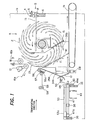
- Fig. 1 is a side view of the delivery according to the embodiment of the present invention.
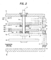
- Fig. 2 is a view on arrow A of Fig. 1 .
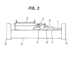
- Fig. 3 is a view on arrow B of Fig. 1 .
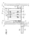
- Fig. 4 is a front view of the delivery according to the embodiment of the present invention.
- Fig. 5 is a plan view of the delivery according to the embodiment of the present invention.
- Fig. 6 is a view on arrows C-C of Fig. 4 .
- Fig. 7 is a view on arrows D-D of Fig. 4 .
- Fig. 8 is a sectional view on arrows E-E of Fig. 5 .
- Fig. 9 is a view on arrow F of Fig. 5 .
- Fig. 10 is a block diagram according to an embodiment of the present invention.
- Fig. 11 is a flowchart showing a discrimination process at the time of changing the folding specification.
- Fig. 12 is a flowchart showing a process at the time of changing the folding specification from the one-time parallel folding to the delta folding.
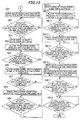
- Fig. 13 is a flowchart showing a process at the time of changing the folding specification from the one-time parallel folding to the two-time parallel folding.
- Fig. 14 is a flowchart showing a process at the time of changing the folding specification from the delta folding to the one-time parallel folding.
- Fig. 15 is a flowchart showing a process at the time of changing the folding specification from the delta folding to the two-time parallel folding.
- Fig. 11 is a flowchart showing a discrimination process at the time of changing the folding specification.
- Fig. 12 is a flowchart showing a process at the time of changing the folding specification from the one-time parallel folding to the delta folding
- FIG. 16 is a flowchart showing a process at the time of changing the folding specification from the two-time parallel folding to the one-time parallel folding.
- Fig. 17 is a flowchart showing a process at the time of changing the folding specification from the two-time parallel folding to the delta folding.
- a fan wheel 2 is pivotally supported between a pair of frames 1a and 1b of the delivery.
- An arrow in Fig. 1 indicates the rotation direction of the fan wheel 2.
- the fan wheel 2 includes four fan wheel members 2a, 2b, 2c and 2d, and these are supported on a supporting shaft 3 with predetermined spacing.
- the fan wheel members 2a and 2b are splined on a spline portion 3a of the supporting shaft 3 to be able to rotate with the supporting shaft 3, and are movable in the axis direction of the supporting shaft 3.
- the fan wheel members 2a and 2b are connected to fan-wheel air cylinders 4 and 5 provided as fan wheel moving means.
- the fan-wheel air cylinders 4 and 5 are attached to a supporting plate 6, which is disposed between the frames 1a and 1b.
- Sliding members 8 and 9, which slide on a rail 7 attached on the supporting plate 6, are attached to one ends of the air cylinders 4 and 5.
- the sliding members 8 and 9 support the fan wheel members 2a and 2b via supporting members 10 and 11.
- the fan wheel members 2a and 2b are pivotally supported by bearings 12 and 13 attached to one ends of the supporting members 10 and 11.
- strippers 14 and 15 are attached to the supporting members 10 and 11.
- a pair of transporting belts 16a and 16b for transporting a signature (the signature 65, 66 or 67 described later) provided as a sheet are looped over roller members 17 and 18.
- the signature which has been transported is ejected from between the roller members 17 and 18, and held by the fan wheel 2.
- a paper delivery belt 19 for receiving the signature which is discharged from the fan wheel 2 and then delivering the signature to a predetermined position.
- Arrows in Fig. 1 indicate the transporting directions of the transporting belts 16a and 16b and the paper delivery belt 19.
- a pair of plate-shaped side guides 20 and 21 for restricting the signature in the width direction, which is temporarily held by the fan wheel 2 are disposed inside the frames 1a and 1b, the side guides 20 and 21 being placed on both sides of the fan wheel 2.
- a pair of brackets 22a and 22b are attached to the back face of the side guide 20, and slide rods 23a and 23b are supported by the upper and lower portions of the brackets 22a and 22b.
- a supporting block 24 slidably supports the slide rods 23a and 23b, and is supported by the frame 1a via an arm 25.
- a pair of brackets 26a and 26b are attached to the back face of the side guide 21, and a side-guide rodless air cylinder 27 provided as side-guide radial-direction moving means is supported between the brackets 26a and 26b.
- a supporting plate 28 is supported by a moving block 27a of the side-guide rodless air cylinder 27, and supports moving rods 28a and 28b, which are disposed perpendicularly to the side-guide rodless air cylinder 27.
- the moving rods 28a and 28b are supported by a supporting block 29 outside the frame 1a.
- the moving rod 28b has a rack shape formed, and the rack and an end of a gear 30 engage with each other.
- the other end of the gear 30 is connected with an end of a gear 31, and engages with a gear 33a of a side-guide encoder 33.
- a side-guide drive motor 32 provided as side-guide width-direction moving means is attached to the gear 31.
- a back guide 34 for restricting the signature in the longitudinal direction (the radial direction of the fan wheel 2) which is temporarily held by the fan wheel 2 is disposed inside the side guides 20 and 21.
- the back guide 34 includes three back guide members 34a, 34b and 34c.
- the back guide members 34a to 34c are supported with predetermined spacing in the width direction of the signature, and are disposed between the fan wheel members 2a, 2b, 2c and 2d, respectively.
- the guide rod 40 is, at both ends thereof, fixed to the supporting plates 35 and 36, and disposed in a state where the guide rod 40 penetrates the guide block 38.
- the guide rod 41 is, at both ends thereof, fixed to the supporting plates 35 and 36, and disposed in a state where the guide rod 41 penetrates the guide blocks 38 and 39.
- the rotation rod 42 is, at both ends thereof, pivotally supported by the supporting plates 35 and 36.
- an external thread portion 42a is formed in the rotation rod 42, and engages with an internal thread portion 38a formed in a block 38A which is fixed to the guide block 38.
- a gear 43 is provided to an end of the rotation rod 42.
- a back-guide drive motor 44 provided as back-guide moving means, which is supported by the supporting plate 35, is placed, and a gear 44a of the back-guide drive motor 44 and the gear 43 engages with each other.
- the back-guide encoder 45 is supported by a bracket 68 which is supported by the frame 1b, and the gear 45a of the back-guide encoder 45 and the rack 37 engage with each other.
- moving rods 46 and 47 and a fixed rod 48 are disposed between the supporting plate 35 and the guide block 38.
- the moving rods 46 and 47 penetrate the supporting plate 35 and the guide block 38. End portions 46a and 47a located outside the guide block 38 are formed on one ends of the moving rods 46 and 47, and connection members 49 and 50 are supported by the other ends thereof.
- One end of the fixed rod 48 penetrates the supporting plate 35 and is fixed to the guide block 38, and the other end thereof is supported by a connection member 51.
- the moving rods 46 and 47 and the fixed rod 48 support the back guide members 34a, 34b and 34c via the connection members 49, 50 and 51. Each of one ends of the connection members 49, 50 and 51 forks and is swingable, so that the angle thereof can be changed.
- Back-guide rodless air cylinders 52 and 53 provided as back-guide moving means, which are supported on the supporting plates 35 and 36 at both ends thereof, are disposed above the moving rods 46 and 47.
- the end portions 46a and 47a of the moving rods 46 and 47 are fixed to the bottom of moving blocks 52a and 53a of the back-guide rodless air cylinders 52 and 53.
- supporting members 54, 55 and 56 are installed on the back-side upper portions of the back guide members 34a, 34b and 34c, respectively.
- a supporting shaft 57 is placed in elongated slots 54a, 55a and 56a opening in the supporting members 54, 55 and 56.
- An arm 59 extended from a supporting plate 58 supports the supporting shaft 57.
- sliding members 8 and 9 slide on the rail 7 as the fan-wheel air cylinders 4 and 5 expand and contract, and the supporting members 10 and 11 slide with this motion, so that the fan wheel members 2a and 2b can move in the axis direction of the supporting shaft 3, that is, in the width direction of the signature. ( Fig. 2 )
- the side guide 20 is freely slidably supported by the supporting block 24, which is supported by the frame 1a, and is thereby movable in the radial direction of the fan wheel 2.
- the side guide 21 is movable in the radial direction of the fan wheel 2 by means of the side-guide rodless air cylinder 27, and is movable in the width direction of the signature by the forward and reverse rotations of the side-guide drive motor 32.
- the side-guide encoder 33 it is possible to sense the position of the side guide 21 in the width direction of the signature from the rotational position of the side-guide drive motor 32. ( Figs. 4 , 6 and 9 )
- the back-guide drive motor 44 is allowed to rotate, whereby the rotation rod 42 is rotated.
- the rotation of the rotation rod 42 allows the rack 37 and the guide blocks 38 and 39 to move toward the fan wheel 2, and allows the fixed rod 48 to move.
- air is fed to the back-guide rodless air cylinders 52 and 53, and the moving blocks 52a and 53a and the end portions 46a and 47a of the moving rods 46 and 47 are pressed against the guide block 38, these members also move toward the fan wheel 2.
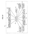
- Fig. 10 is a block diagram showing the configuration of a printing press provided with the delivery according to the present embodiment.
- a printing press 61 includes a controller 60.
- the controller 60 is connected with the fan-wheel air cylinders 4 and 5; the side-guide rodless cylinder 27; the side-guide drive motor 32; the side-guide encoder 33; the back-guide drive motor 44; the back-guide encoder 45; the back-guide rodless air cylinders 52 and 53; a printing-press speed detector 62; a folding specification input part 63; and a display device 64.
- the controller 60 When a folding specification is inputted in the folding specification input part 63 by an operator, on the basis of the signal, the controller 60 performs control sequentially so as to drive the side-guide drive motor 32 and the back-guide drive motor 44, and feed air to the air cylinders 4 and 5, the side-guide rodless cylinder 27, and the back-guide rodless air cylinders 52 and 53.
- the fan wheel 2 the side guide 21 and the back guide 34 are moved to predetermined positions.
- the positions of the side guide 21 and the back guide 34 are sensed by the side-guide encoder 33 and the back-guide encoder 45, respectively, and an operator can view the positions on the display device 64 such as a display.
- the controller 60 moves the side guide 21 placed in a guide position for a signature in the width direction of the signature in response to the drive speed of the printing press 61, and suitably guides the signature.
- the delivery according to the present invention is also capable of supporting all these folding specifications.
- step S1 a folding specification of any of one-time parallel folding, two-time parallel folding and delta folding is newly inputted to the folding specification input part 63.
- step S2 it is determined whether or not the current folding specification is the one-time parallel folding. If the result is Yes, in step S3, it is determined whether or not the folding specification which is newly inputted to the folding specification input part 63 in step S1 is the one-time parallel folding.
- step S3 it is determined whether or not the folding specification which is newly inputted to the folding specification input part 63 in step S1 is the one-time parallel folding.
- the process will end.
- the controller 60 does not drive the side-guide drive motor 32 and the back-guide drive motor 44, and does not allow the fan-wheel air cylinders 4 and 5, the side-guide rodless cylinder 27, and back-guide rodless air cylinders 52 and 53 to operate. Therefore, the fan wheel members 2a and 2b remain placed in the rotation positions R1 and R2, the side guide 21 remains placed in the guide position M1', and the back guide members 34a, 34b and 34c remain placed in the guide position N1.
- step S4 it is determined in step S4 whether or not the folding specification which is newly inputted to the folding specification input part 63 in step S1 is the delta folding.
- the process continues to a process shown in later-described Fig. 12 . That is, the folding specification in this case is changed from the one-time parallel folding to the delta folding.
- step S4 the process continues to a process shown in later-described Fig. 13 . That is, the folding specification in this case is changed from the one-time parallel folding to the two-time parallel folding.
- step S5 it is determined in step S5 whether or not the current folding specification is the delta folding. If the result is Yes, it is determined in step S6 whether or not the folding specification which is newly inputted to the folding specification input part 63 in step S1 is the one-time parallel folding.
- step S6 it is determined in step S6 whether or not the folding specification which is newly inputted to the folding specification input part 63 in step S1 is the one-time parallel folding.
- the process continues to a process shown in later-described Fig. 14 . That is, the folding specification in this case is changed from the delta folding to the one-time parallel folding.
- step S7 it is determined in step S7 whether or not the folding specification which is newly inputted to the folding specification input part 63 in step S1 is the delta folding. If the result is Yes, the process will end.
- the controller 60 does not drive the side-guide drive motor 32 and the back-guide drive motor 44, and does not allow the fan-wheel air cylinders 4 and 5, the side-guide rodless cylinder 27, and back-guide rodless air cylinders 52 and 53 to operate. Therefore, the fan wheel members 2a remains placed in the retraction position r1, the fan wheel members 2b remains placed in the rotation position R2, the side guide 21 remains placed in the guide position M2', the back guide member 34a remains placed in the retraction position n1, and the back guide members 34b and 34c remain placed in the guide position N1.
- step S7 the process continues to a process shown in later-described Fig. 15 . That is, the folding specification in this case is changed from the delta folding to the two-time parallel folding.
- step S8 it is determined in step S8 whether or not the folding specification which is newly inputted to the folding specification input part 63 in step S1 is the one-time parallel folding.
- the process continues to a process shown in later-described Fig. 16 . That is, the folding specification in this case is changed from the two-time parallel folding to the one-time parallel folding.
- step S9 it is determined in step S9 whether or not the folding specification which is newly inputted to the folding specification input part 63 in step S1 is the delta folding. If the result is Yes, the process continues to a process shown in later-described Fig. 17 . That is, the folding specification in this case is changed from the two-time parallel folding to the delta folding.
- step S9 the process will end. Specifically, since the folding specification in this case is changed from the two-time parallel folding to the two-time parallel folding, the controller 60 does not drive the side-guide drive motor 32 and the back-guide drive motor 44, and does not allow the fan-wheel air cylinders 4 and 5, the side-guide rodless cylinder 27, and back-guide rodless air cylinders 52 and 53 to operate. Therefore, the fan wheel members 2a and 2b remain placed in the retraction positions r1 and r2, the side guide 21 remains placed in the guide position M3, the back guide members 34a and 34b remain placed in the retraction position n1, and the back guide member 34c remains placed in the guide position N1.
- step SA1 the back-guide drive motor 44 is driven to rotate in the other direction.
- step SA2 it is determined whether or not it is detected by the back-guide encoder 45 that the back guide members 34a, 34b and 34c have moved to the retraction position n1.
- the drive of the back-guide drive motor 44 is stopped in step SA3. If the result is No, the detection is continued.
- step SA4 the side-guide rodless air cylinder 27 is allowed to operate in the other direction (toward the upstream side in the transporting direction of the signature).
- step SA5 it is determined whether or not the side-guide rodless air cylinder 27 has completed extending in the other direction. In other words, it is determined whether or not the side guide 21 has moved from the guide position M1' to the retraction position m1.
- the fan-wheel air cylinder 4 is allowed to operate in the other direction (toward the frame 1a side) in step SA6. If the result is No, the detection is continued.
- step SA7 it is determined whether or not the fan-wheel air cylinder 4 has completed extending. In other words, it is determined whether or not the fan wheel member 2a has moved from the guide position R1 to the retraction position r1.
- step SA8 it is determined whether or not the back-guide drive motor 32 is driven to rotate in one direction in step SA8. If the result is No, the detection is continued.
- step SA9 it is determined whether or not it is detected by the side-guide encoder 33 that the side guide 21 has moved from the retraction position m1 to the retraction position m2.
- the drive of the side-guide drive motor 32 is stopped in step SA10. If the result is No, the detection is continued.
- step SA11 the side-guide rodless air cylinder 27 is allowed to operate in one direction (toward the downstream side in the transporting direction of the signature).
- step SA12 it is determined whether or not the side-guide rodless air cylinder 27 has completed extending in one direction. In other words, it is determined whether or not the side guide 21 has moved from the retraction position m2 to the guide position M2'.
- the back-guide drive motor 44 is driven to rotate in one direction in step SA13. If the result is No, the detection is continued.
- step SA14 the back-guide rodless air cylinder 52 is allowed to operate in the other direction (toward the upstream side in the transporting direction of the signature).
- step SA15 it is determined whether or not it is detected by the back-guide encoder 45 that the back guide members 34b and 34c have moved to the guide position N1.
- step SA16 it is determined in step SA16 whether or not the back-guide rodless air cylinder 52 has completed extending in the other direction. In other words, it is determined whether or not the back guide member 34a has moved to the retraction position n1.
- the process will end. If the result is No in step SA15 or SA16, the detection is continued.
- step SB1 the back-guide drive motor 44 is driven to rotate in the other direction.
- step SB2 it is determined whether or not it is detected by the back-guide encoder 45 that the back guide members 34a, 34b and 34c have moved to the retraction position n1.
- the drive of the back-guide drive motor 44 is stopped in step SB3. If the result is No, the detection is continued.
- step SB4 the side-guide rodless air cylinder 27 is allowed to operate in the other direction.
- step SB5 it is determined whether or not the side-guide rodless air cylinder 27 has completed extending in the other direction. In other words, it is determined whether or not the side guide 21 has moved from the guide position M1' to the retraction position m1.
- the fan-wheel air cylinders 4 and 5 are allowed to operate in the other direction (toward the frame 1a side) in step SB6. If the result is No, the detection is continued.
- step SB7 it is determined whether or not the fan-wheel air cylinders 4 and 5 have completed extending. In other words, it is determined whether or not the fan wheel members 2a and 2b have moved from the guide positions R1 and R2 to the retraction positions r1 and r2.
- the side-guide drive motor 32 is driven to rotate in one direction in step SB8. If the result is No, the detection is continued.
- step SB9 it is determined whether or not it is detected by the side-guide encoder 33 that the side guide 21 has moved from the retraction position m1 to the retraction position m2.
- the drive of the side-guide drive motor 32 is stopped in step SB10. If the result is No, the detection is continued.
- step SB11 the side-guide rodless air cylinder 27 is allowed to operate in one direction.
- step SB12 it is determined whether or not the side-guide rodless air cylinder 27 has completed extending in one direction. In other words, it is determined whether or not the side guide 21 has moved from the retraction position m2 to the guide position M2'.
- the side-guide drive motor 32 is driven to rotate in one direction in step SB13. If the result is No, the detection is continued.
- step SB14 it is determined whether or not it is detected by the side-guide encoder 33 that the side guide 21 has moved from the guide position M2' to the guide position M3'.
- the back-guide drive motor 44 is driven to rotate in one direction in step SB15. If the result is No, the detection is continued.
- step SB16 the back-guide rodless air cylinders 52 and 53 are allowed to operate in the other direction (toward the upstream side in the transporting direction of the signature).
- step SB17 it is determined whether or not it is detected by the back-guide encoder 45 that the back guide member 34c has moved to the guide position N1.
- step SB18 it is determined in step SB18 whether or not the back-guide rodless air cylinders 52 and 53 have completed extending in the other direction. In other words, it is determined whether or not the back guide members 34a and 34b have moved to the retraction position n1.
- the process will end. If the result is No in step SB17 or SB18, the detection is continued.
- step SC1 the back-guide drive motor 44 is driven to rotate in the other direction.
- step SC2 it is determined whether or not it is detected by the back-guide encoder 45 that the back guide members 34b and 34c have moved to the retraction position n1.
- the drive of the back-guide drive motor 44 is stopped in step SC3. If the result is No, the detection is continued.
- step SC4 the side-guide rodless air cylinder 27 is allowed to operate in the other direction.
- step SC5 it is determined whether or not the side-guide rodless air cylinder 27 has completed extending in the other direction. In other words, it is determined whether or not the side guide 21 has moved from the guide position M2' to the retraction position m2.
- the fan-wheel air cylinder 4 is allowed to operate in one direction (toward the frame 1b side) in step SC6. If the result is No, the detection is continued.
- step SC7 it is determined whether or not the fan-wheel air cylinder 4 has completed retraction. In other words, it is determined whether or not the fan wheel member 2a has moved from the retraction position r1 to the guide position R1.
- step SC8 it is determined whether or not the back-guide drive motor 32 is driven to rotate in the other direction in step SC8. If the result is No, the detection is continued.
- step SC9 it is determined whether or not it is detected by the side-guide encoder 33 that the side guide 21 has moved from the retraction position m2 to the retraction position m1.
- the drive of the side-guide drive motor 32 is stopped in step SC10. If the result is No, the detection is continued.
- step SC11 the side-guide rodless air cylinder 27 is allowed to operate in one direction.
- step SC12 it is determined whether or not the side-guide rodless air cylinder 27 has completed extending in one direction. In other words, it is determined whether or not the side guide 21 has moved from the retraction position m1 to the guide position M1'.
- the back-guide rodless air cylinder 52 is allowed to operate in one direction (toward the upstream side in the transporting direction of the signature) in step SC13. If the result is No, the detection is continued.
- step SC14 the back-guide drive motor 44 is driven to rotate in one direction.
- step SC15 it is determined whether or not it is detected by the back-guide encoder 45 that the back guide members 34a, 34b and 34c have moved to the guide position N1. Here, if the result is Yes, the process will end. If the result is No, the detection is continued.
- step SD1 the back-guide drive motor 44 is driven to rotate in the other direction.
- step SD2 it is determined whether or not it is detected by the back-guide encoder 45 that the back guide members 34b and 34c have moved to the retraction position n1.
- the drive of the back-guide drive motor 44 is stopped in step SD3. If the result is No, the detection is continued.
- step SD4 the side-guide rodless air cylinder 27 is allowed to operate in the other direction.
- step SD5 it is determined whether or not the side-guide rodless air cylinder 27 has completed extending in the other direction. In other words, it is determined whether or not the side guide 21 has moved from the guide position M2' to the retraction position m2.
- the result is Yes, the fan-wheel air cylinder 5 is allowed to operate in the other direction in step SD6. If the result is No, the detection is continued.
- step SD7 it is determined whether or not the fan-wheel air cylinder 5 has completed extending. In other words, it is determined whether or not the fan wheel member 2b has moved from the guide position R2 to the retraction position r2.
- step SD8 it is determined whether or not the side-guide rodless air cylinder 27 is allowed to operate in one direction in step SD8. If the result is No, the detection is continued.
- step SD9 it is determined whether or not the side-guide rodless air cylinder 27 has completed extending in one direction. In other words, it is determined whether or not the side guide 21 has moved from the retraction position m2 to the guide position M2'.
- the side-guide drive motor 32 is driven to rotate in one direction in step SD10. If the result is No, the detection is continued.
- step SD11 it is determined whether or not it is detected by the side-guide encoder 33 that the side guide 21 has moved from the guide position M2' to the guide position M3'.
- step SD12 the drive of the side-guide drive motor 32 is stopped in step SD12. If the result is No, the detection is continued.
- step SD13 the back-guide drive motor 44 is driven to rotate in one direction.
- step SD14 the back-guide rodless air cylinder 53 is allowed to operate in the other direction.
- step SD15 it is determined whether or not it is detected by the back-guide encoder 45 that the back guide member 34c has moved to the guide position N1.
- step SD16 it is determined in step SD16 whether or not the back-guide rodless air cylinder 53 has completed extending in the other direction. In other words, it is determined whether or not the back guide member 34b has moved to the retraction position n1.
- the process will end. If the result is No in step SD15 or SD16, the detection is continued.
- step SE1 the back-guide drive motor 44 is driven to rotate in the other direction.
- step SE2 it is determined whether or not it is detected by the back-guide encoder 45 that the back guide member 34c has moved to the retraction position n1.
- the drive of the back-guide drive motor 44 is stopped in step SE3. If the result is No, the detection is continued.
- step SE4 the back-guide drive motor 32 is driven to rotate in the other direction.
- step SE5 it is determined whether or not it is detected by the side-guide encoder 33 that the side guide 21 has moved from the guide position M3' to the guide position M2'. Here, if the result is Yes, the drive of the side-guide drive motor 32 is stopped in step SE6. If the result is No, the detection is continued.
- step SE7 the side-guide rodless air cylinder 27 is allowed to operate in the other direction.
- step SE8 it is determined whether or not the side-guide rodless air cylinder 27 has completed extending in the other direction. In other words, it is determined whether or not the side guide 21 has moved from the guide position M2' to the retraction position m2.
- the fan-wheel air cylinders 4 and 5 are allowed to operate in one direction (toward the frame 1b side) in step SE9. If the result is No, the detection is continued.
- step SE10 it is determined whether or not the fan-wheel air cylinders 4 and 5 have completed retraction. In other words, it is determined whether or not the fan wheel members 2a and 2b have moved from the retraction positions r1 and r2 to the guide positions R1 and R2.
- step SE12 it is determined whether or not it is detected by the side-guide encoder 33 that the side guide 21 has moved from the retraction position m2 to the retraction position m1.
- step SE13 it is determined whether or not the side guide encoder 33 that the side guide 21 has moved from the retraction position m2 to the retraction position m1.
- the drive of the side-guide drive motor 32 is stopped in step SE13. If the result is No, the detection is continued.
- step SE14 the side-guide rodless air cylinder 27 is allowed to operate in one direction.
- step SE15 it is determined whether or not the side-guide rodless air cylinder 27 has completed extending in one direction. In other words, it is determined whether or not the side guide 21 has moved from the retraction position m1 to the guide position M1'.
- the back-guide drive motor 44 is driven to rotate in one direction in step SE16. If the result is No, the detection is continued.
- step SE17 the back-guide rodless air cylinders 52 and 53 are allowed to operate in one direction (toward the downstream side in the transporting direction of the signature).
- step SE18 it is determined whether or not it is detected by the back-guide encoder 45 that the back guide members 34a, 34b and 34c have moved to the guide position N1. Here, if the result is Yes, the process will end. If the result is No, the detection is continued.
- step SF1 the back-guide drive motor 44 is driven to rotate in the other direction.
- step SF2 it is determined whether or not it is detected by the back-guide encoder 45 that the back guide member 34c has moved to the retraction position n1.
- the drive of the back-guide drive motor 44 is stopped in step SF3. If the result is No, the detection is continued.
- step SF4 the back-guide drive motor 32 is driven to rotate in the other direction.
- step SF5 it is determined whether or not it is detected by the side-guide encoder 33 that the side guide 21 has moved from the guide position M3' to the guide position M2'. Here, if the result is Yes, the drive of the side-guide drive motor 32 is stopped in step SF6. If the result is No, the detection is continued.
- step SF7 the side-guide rodless air cylinder 27 is allowed to operate in the other direction.
- step SF8 it is determined whether or not the side-guide rodless air cylinder 27 has completed extending in the other direction. In other words, it is determined whether or not the side guide 21 has moved from the guide position M2' to the retraction position m2.
- the result is Yes, the fan-wheel air cylinder 5 is allowed to operate in one direction in step SF9. If the result is No, the detection is continued.
- step SF10 it is determined whether or not the fan-wheel air cylinder 5 has completed retraction. In other words, it is determined whether or not the fan wheel member 2b has moved from the retraction position r2 to the guide position R2.
- step SF12 it is determined whether or not the side-guide rodless air cylinder 27 has completed extending in one direction. In other words, it is determined whether or not the side guide 21 has moved from the retraction position m2 to the guide position M2'.
- the back-guide drive motor 44 is driven to rotate in one direction in step SF13. If the result is No, the detection is continued.
- step SF14 the back-guide rodless air cylinder 53 is driven to rotate in one direction.
- step SF15 it is determined whether or not it is detected by the back-guide encoder 45 that the back guide members 34b and 34c have moved to the guide position N1. Here, if the result is Yes, the process will end. If the result is No, the detection is continued.
- the above described operations make it possible to easily move the positions in which the fan wheel members 2a, 2b, 2c and 2d, the back guide members 34a, 34b and 34c, and the side guide 21 are placed, even when the fan wheel members 2a, 2b, 2c and 2d rotationally transport each of the signatures 65, 66 and 67 which have different folding specifications.
- the side guide 21 placed in the guide positions is designed to be moved by the controller 60 in the width direction of the signatures 65, 66 and 67, that is, between the guide positions M1, M2 and M3 and the guide positions M1', M2' and M3', respectively, in response to the drive speed of the printing press 61 (the transporting speed of the signature).
- the controller 60 controls the transport speed of the signatures 65, 66 and 67, that is, between the guide positions M1, M2 and M3 and the guide positions M1', M2' and M3', respectively, in response to the drive speed of the printing press 61 (the transporting speed of the signature).
- the side guide 21 is placed with the side guide 21 spaced apart from the guide positions M1, M2 and M3 to the guide positions M1', M2' and M3' (20 to 80 mm, for example). This prevents the signatures 65, 66 and 67 which have been transported from bumping into the side guide 21, and thereby inhibiting a paper jam and the like from occurring.
- the side guide 21 is so designed that the side guide 21 gradually moves from the guide positions M1', M2' and M3' to the guide positions M1, M2 and M3, respectively, as the drive speed of the printing press 61 increases, and, when the printing press 61 reaches normal operation, the side guide 21 is eventually placed in the guide position M1, M2 or M3. Incidentally, from the time of normal operation to the time of shutting down of the printing press 61, the side guide 21 may be placed in the guide positions M1', M2' and M3'.
- the side guide 21 may be placed in the guide place M1, M2 or M3 from before starting up the printing press 61.
- the back guide members 34a, 34b and 34c placed in the guide position N1 may be designed to be moved in the longitudinal direction of the signatures 65, 66 and 67, that is, between the guide position N1 and the retraction position n1, in response to the drive speed of the printing press 61 by the controller 60.
- This is because of the following reasons. When a signature is transported at a low speed, the signature has little momentum, lacks stability, and is thus transported askew. Therefore, when the back guide is placed in accordance with the length in the longitudinal direction of the signature, there is a possibility that the signature bumps into the back guide.
- the back guide members 34a, 34b and 34c are placed with the back guide members 34a, 34b and 34c spaced apart from the guide position N1 to the retraction position n1 (20 to 80 mm, for example). This prevents the signatures 65, 66 and 67 which have been transported from bumping into the back guide members 34a, 34b and 34c, and thereby preventing a paper jam and the like from occurring.
- the back guide members 34a, 34b and 34c are so designed that the back guide members 34a, 34b and 34c gradually move from the retraction position n1 to the guide position N1 as the drive speed of the printing press 61 increases, and, when the printing press 61 reaches normal operation, the back guide members 34a, 34b and 34c are eventually placed in the guide position N1.
- the back guide members 34a, 34b and 34c are designed to move from the guide position N1 to the retraction position n1, from the time of normal operation to the time of shutting down of the printing press 61.
- the delivery includes: the fan wheel members 2a, 2b, 2c and 2d for holding and rotationally transporting the signatures 65, 66 and 67 delivered from the printing press 61; the pair of side guides 20 and 21 for restricting the signatures 65, 66 and 67 in the width direction which are held in the fan wheel members 2a, 2b, 2c and 2d; the side-guide rodless air cylinder 27 for moving at least one side guide 21 between the side-guide guide positions M1, M2, M3, M1', M2' and M3' for guiding the signatures 65, 66 and 67 and the side-guide retraction positions m1 and m2 for retraction to the outside of the fan wheel members 2a, 2b, 2c and 2d in the radial direction thereof; the side-guide drive motor 32 for moving at least one side guide 21 in the width direction of the signatures 65, 66 and 67; and the controller 60 which controls the side-guide rodless air cylinder 27 and the side-guide
- the rodless air cylinder 27 for moving the signatures 65, 66 and 67 in the transporting direction is supported by the supporting plate 28 which is moved by the side-guide drive motor 32 in the paper width direction which is the direction orthogonal to the transporting direction, and the supporting plate 28 is supported by the frame 1a via the supporting block 29, it is possible to easily control the side guide 21.
- the delivery includes: the back guide members 34a, 34b and 34c, which are provided between the pair of side guides 20 and 21, and which guide the rear ends of the signatures 65, 66 and 67 which are held in the fan wheel members 2a, 2b, 2c and 2d; and the back-guide drive motor 44 and the back-guide rodless air cylinders 52 and 53 for moving the back guide members 34a, 34b and 34c between the guide position N1 for guiding the signatures 65, 66 and 67 and the retraction position n1 for retraction to the outside of the fan wheel members 2a, 2b, 2c and 2d in the radial direction thereof, and the retraction position n1 is placed in such a manner that the side guide 21 can move in the width direction of the signatures 65, 66 and 67, it is possible to automatically move the back guide members 34a, 34b and 34c in synchronization with the movement of the fan wheel members 2a and 2b.
- the controller 60 moves the side guide 21 to the retraction position m1 or m2 after moving the back guide member 34a, 34b and 34c to the retraction position n1
- the controller 60 moves the back guide members 34a, 34b and 34c to the guide position N1 after moving the side guide 21 to the guide position M1, M2, M3, M1', M2' or M3'
- controller 60 moves the side guide 21 to the retraction position m1 or m2 after moving the back guide members 34a, 34b and 34c to the retraction position n1, and then moves the side guide 21 to the guide position M1, M2, M3, M1', M2' or M3', it is possible to prevent the side guide 21 from coming into contact with the back guide members 34a, 34b and 34c.
- back-guide drive motor 44 and the back-guide rodless air cylinders 52 and 53 are provided, it is possible to easily move the back guide members 34a, 34b and 34c to the guide position N1 and the retraction position n1 in accordance with the length in the width direction of the signatures 65, 66 and 67.
- back guide member 34c is fixed to the guide block 38, and the back guide members 34b and 34c are inserted into the guide block 38 in such a manner that the forward movement of the back guide members 34b and 34c is restricted, it is possible to easily control the back guide members 34a, 34b and 34c.
- back guide members 34a, 34b and 34c are moved between the guide position N1 and the retraction position n1 by use of the movement of the guide block 38, it is possible to easily control the back guide members 34a, 34b and 34c in a simple configuration.
- the other side guide 20 is fixed near the back guide member 34c, it is possible to stably guide one end of the signature 65, 66 or 67.
- the fan-wheel members 2a and 2b are supported freely movably in the width direction of the signatures 65, 66 and 67, it is possible to automatically move the fan wheel members 2a and 2b at the time of changing the folding specification.
- the fan-wheel air cylinders 4 and 5, which move the fan wheel members 2a and 2b in the width direction of the signatures 65, 66 and 67, are provided, it is possible to easily control the fan wheel members 2a and 2b.
- the controller 60 moves the back guide members 34a, 34b and 34c to the retraction position n1, moves the side guide 21 to the retraction position m1 or m2, moves the fan wheel members 2a and 2b to a position corresponding to the signature 65, 66 or 67, moves the side guide 21 to the guide position M1, M2, M3, M1', M2' or M3', and then moves the back guide members 34a, 34b and 34c to the guide position N1, it is possible to easily control the fan wheel members 2a and 2b, side guide 21, and the back guide members 34a, 34b and 34c and to prevent the contact thereof with another at the time of changing the folding specification.
- the side guide 20 may be provided with an air cylinder, a drive motor and the like, so that the side guide 20 is allowed to be able to move in the radial direction of the fan wheel 2 or in the width direction of the signatures 65, 66 and 67 as in the case of the side guide 21.
- the fan wheel 2 includes four fan wheel members 2a, 2b, 2c and 2d
- the back guide 34 includes three guide members 34a, 34b and 34c in the present embodiment, the numbers of these members are not limited to these numbers.
- the present invention can be applied to a delivery of a folding machine included in a rotary press, the delivery automatically performing position adjustment of guide members in accordance with the size of a signature, and moving of the guide members in response to the drive speed of the printing press at the time of changing the folding specification.
- the delivery since the delivery includes:
- the side-guide retraction positions are placed outside the peripheries of the fan wheel when the side guide is moved in the axis direction, it is possible to prevent the side guide from coming into contact with the fan wheel.
- the side-guide radial-direction moving means and the side-guide width-direction moving means are made as side-guide moving means in which the side-guide width-direction moving means supports the side-guide radial-direction moving means, it is possible to easily control the side guide.
- the side-guide radial-direction moving means is a rodless air cylinder, and the side-guide width-direction moving means is a motor, it is possible to easily control the side guide.
- the delivery since, in the delivery according to the third aspect, the delivery further includes:
- the control means moves the side guide to the side-guide retraction position after moving the back guide to the side-guide retraction position, and the control means moves the back guide to the back-guide guide position after moving the side guide to the side-guide guide position, it is possible to prevent the side guide from coming into contact with the back guide.
- the delivery since, in the delivery according to the first aspect, the delivery further includes:
- the back guide since, in the delivery according to the fifth aspect, the back guide includes a plurality of back guide members in the width direction of the sheet, and that the plurality of the back guide members are individually provided with the back guide moving means, it is possible to allow the plurality of back guide members to perform guiding in accordance with the length in the width direction of the sheet.
- the plurality of back guide members are moved between the back-guide guide position and the side-guide retraction position by use of the movement of the guide block, it is possible to easily control the back guide members.
- the other side guide is immovably supported and is fixed near the back guide member, it is possible to stably guide the sheet.
- the fan wheel includes a plurality of fan wheel members in the width direction of the sheet, and that at least one fan wheel member out of the plurality of fan wheel members is supported freely movably in the width direction of the sheet, it is possible to automatically move the fan wheel members at the time of changing the folding specification.
- fan wheel moving means moving the plurality of fan wheel members in the width direction of the sheet is provided, it is possible to easily control the fan wheel members.
- the control means moves the back guide to the side-guide retraction position, moves the side guide to the side-guide retraction position, moves the fan wheel to a position corresponding to the sheet, moves the side guide to the side-guide guide position, and then moves the back guide to the back-guide guide position, it is possible to easily control the side guide, the fan wheel and the back guide and to prevent the contact thereof with another at the time of changing the folding specification.
Landscapes
- Engineering & Computer Science (AREA)
- Mechanical Engineering (AREA)
- Folding Of Thin Sheet-Like Materials, Special Discharging Devices, And Others (AREA)
- Discharge By Other Means (AREA)
- Feeding Of Articles By Means Other Than Belts Or Rollers (AREA)
- Massaging Devices (AREA)
- Noodles (AREA)
- Surgical Instruments (AREA)
Claims (17)
- Ausgabevorrichtung mit:einem Fächerrad (2), das ein von einer Druckpresse (61) ausgegebenes Blatt (65, 66, 67) hält und durch Drehbewegung transportiert;gekennzeichnet durch:ein Paar Seitenführungen (20, 21), die das Blatt (65, 66, 67), das in dem Fächerrad (2) gehalten ist, in der Breitenrichtung eingrenzen;Seitenführungs-Radialrichtung-Bewegungsmittel (27) zum Bewegen wenigstens einer Seitenführung (21) zwischen einer Führungsposition (M1, M2, M3, M1', M2', M3') der Seitenführung zum Führen des Blatts (65, 66, 67) und einer Rückzugsposition (m1, m2) der Seitenführung zum Zurückziehen an die Außenseite des Fächerrads (2) in radialer Richtung davon;Seitenführungs-Breitenrichtung-Bewegungsmittel (32) zum Bewegen wenigstens einer Seitenführung (21) in der Breitenrichtung des Blatts (65, 66, 67); undeiner Steuereinrichtung (60) zum Steuern der Seitenführungs-Radialrichtung-Bewegungsmittel (27) und der Seitenführungs-Breitenrichtung-Bewegungsmittel (32) auf solch eine Weise, dass sich die eine Seitenführung (21) in Übereinstimmung mit der Länge in Breitenrichtung des Blatts (65, 66, 67) bewegt.
- Ausgabevorrichtung nach Anspruch 1, dadurch gekennzeichnet, dass
sich die Seitenführungs-Rückzugspositionen (m1, m2) außerhalb der Peripherie des Fächerrads (2) befinden, wenn die Seitenführung (21) in Richtung der Achse bewegt wird. - Ausgabevorrichtung nach Anspruch 1, dadurch gekennzeichnet, dass
die Seitenführungs-Radialrichtung-Bewegungsmittel (27) und die Seitenführungs-Breitenrichtung-Bewegungsmittel (32) als Seitenführungs-Bewegungseinrichtung ausgestaltet sind, in der die Seitenführungs-Breitenrichtung-Bewegungsmittel (32) die Seitenführungs-Radialrichtung-Bewegungsmittel (27) halten. - Ausgabevorrichtung nach Anspruch 3, dadurch gekennzeichnet, dass
die Seitenführungs-Radialrichtung-Bewegungsmittel (27) ein stangenloser Luftzylinder sind und die Seitenführungs-Breitenrichtung-Bewegungsmittel (32) ein Motor sind. - Ausgabevorrichtung nach Anspruch 3, die ferner aufweist:eine hintere Führung (34), die zwischen dem Paar Seitenführungen (20, 21) vorgesehen ist und die das hintere Ende des Blatts (65, 66, 67), das in dem Fächerrad (2) gehalten ist, führt; undBewegungsmittel (44, 52, 53) für die hintere Führung, die die hintere Führung (34) zwischen einer Führungsposition (N1) der hinteren Führung zum Führen des Blatts (65, 66, 67) und einer zurückgezogenen Position (n1) zum Zurückziehen auf die Außenseite des Fächerrads (2) in radialer Richtung davon bewegen,wobei die zurückgezogene Position (n1) derart platziert ist, dass sich die Seitenführung (21) in der Breitenrichtung des Blatts (65, 66, 67) bewegen kann.
- Ausgabevorrichtung nach Anspruch 5, dadurch gekennzeichnet, dass
die Steuereinrichtung (60) nach dem Bewegen der hinteren Führung (34) in die zurückgezogene Position (n1) die Seitenführung (21) in die zurückgezogene Position (m1, m2) der Seitenführung bewegt und die Steuereinrichtung (60) nach dem Bewegen der Seitenführung (21) in die Führungsposition (M1, M2, M3, M1', M2', M3') der Seitenführung die hintere Führung (34) in die Führungsposition (N1) der hinteren Führung bewegt. - Ausgabevorrichtung nach Anspruch 1, die ferner aufweist:eine hintere Führung (34), die zwischen dem Paar Seitenführungen (20, 21) vorgesehen ist und die das hintere Ende des Blatts (65, 66, 67), das in dem Fächerrad (2) gehalten ist, führt; undBewegungsmittel (44, 52, 53) für die hintere Führung, die die hintere Führung (34) zwischen einer Führungsposition (N1) der hinteren Führung zum Führen des Blatts (65, 66, 67) und einer zurückgezogenen Position (n1) zum Zurückziehen auf die Außenseite des Fächerrads (2) in radialer Richtung davon bewegen,wobei die Steuereinrichtung (60) nach dem Bewegen der hinteren Führung (34) in die zurückgezogene Position (n1) die Seitenführung (21) in die zurückgezogene Position (m1, m2) der Seitenführung bewegt und dann die Seitenführung (21) in die Führungsposition (M1, M2, M3, M1', M2', M3') der Seitenführung bewegt.
- Ausgabevorrichtung nach Anspruch 5, dadurch gekennzeichnet, dass
die hintere Führung (34) in Breitenrichtung des Blatts (65, 66, 67) eine Anzahl hinterer Führungselemente (34a, 34b, 34c) aufweist und
die Anzahl der hinteren Führungselemente (34a, 34b, 34c) einzeln mit den Bewegungsmitteln (44, 52, 53) der hinteren Führung versehen ist. - Ausgabevorrichtung nach Anspruch 8, dadurch gekennzeichnet, dass
eines der hinteren Führungselemente (34c) der Anzahl hinterer Führungselemente (34a, 34b, 34c) an einem Führungsblock (38) fixiert ist und ein anderes hinteres Führungselement (34a, 34b) in den Führungsblock (38) eingesetzt ist und die Vorwärtsbewegung davon durch den Führungsblock (38) begrenzt ist. - Ausgabevorrichtung nach Anspruch 9, die ferner aufweist:die Anzahl der hinteren Führungselemente (34a, 34b, 34c) wird durch Verwendung der Bewegung des Führungsblocks (38) zwischen der Führungsposition (N1) der hinteren Führung und der zurückgezogenen Position (n1) bewegt.
- Ausgabevorrichtung nach Anspruch 9, dadurch gekennzeichnet, dass
die andere Seitenführung (20) unbeweglich gehalten ist und nahe dem an dem Führungsblock befestigten hinteren Führungselement (34c) befestigt ist. - Ausgabevorrichtung nach Anspruch 1, dadurch gekennzeichnet, dass
das Fächerrad (2) in der Breitenrichtung des Blatts (65, 66, 67) eine Anzahl von Fächerradelementen (2a, 2b, 2c, 2d) aufweist und
wenigstens ein Fächerradelement (2a, 2b) der Anzahl von Fächerradelementen (2a, 2b, 2c, 2d) in der Breitenrichtung des Blatts (65, 66, 67) bewegbar gehalten ist. - Ausgabevorrichtung nach Anspruch 12, dadurch gekennzeichnet, dass
Fächerrad-Bewegungsmittel (4, 5) vorgesehen sind, die die Anzahl von Fächerradelementen (2a, 2b) in der Breitenrichtung des Blatts (65, 66, 67) bewegen. - Ausgabevorrichtung nach Anspruch 5, dadurch gekennzeichnet, dass
die Steuereinrichtung (60) die hintere Führung (34a, 34b, 34c, 34d) in die zurückgezogene Position (n1) bewegt, die Seitenführung (21) in die zurückgezogene Position (m1, m2) der Seitenführung bewegt, das Fächerrad (2, 2a, 2b, 2c, 2d) in eine Position entsprechend dem Blatt (65, 66, 67) bewegt, die Seitenführung (21) in die Führungsposition (M1, M2, M3, M1', M2', M3') der Seitenführung bewegt und dann die hintere Führung (34, 34a, 34b, 34c) in die Führungsposition (N1) der hinteren Führung bewegt. - Ausgabevorrichtung nach Anspruch 1, dadurch gekennzeichnet, dass sie ferner ein Faltspezifikations-Eingabeteil (63) aufweist, in das eine Faltspezifikation eingegeben ist, und dass die Steuereinrichtung (60) zum Steuern der Seitenführungs-Radialrichtung-Bewegungsmittel (27) und der Seitenführungs-Breitenrichtung-Bewegungsmittel (32) auf der Basis der in ein Faltspezifikations-Eingabeteil eingegebenen Faltspezifikation arbeitet.
- Ausgabevorrichtung nach Anspruch 5, dadurch gekennzeichnet, dass die Steuereinrichtung (60) die Seitenführungs-Radialrichtung-Bewegungsmittel (27), die Seitenführungs-Breitenrichtung-Bewegungsmittel (32) und die Bewegungsmittel (44, 52, 53) der hinteren Führung auf der Basis der in ein Faltspezifikations-Eingabeteil eingegebenen Faltspezifikation steuert.
- Ausgabevorrichtung nach Anspruch 13, dadurch gekennzeichnet, dass die Steuereinrichtung (60) die Seitenführungs-Radialrichtung-Bewegungsmittel (27), die Seitenführungs-Breitenrichtung-Bewegungsmittel (32), die Bewegungsmittel (44, 52, 53) der hinteren Führung und die Fächerrad-Bewegungsmittel (4, 5) auf der Basis der in ein Faltspezifikations-Eingabeteil eingegebenen Faltspezifikation steuert.
Applications Claiming Priority (4)
| Application Number | Priority Date | Filing Date | Title |
|---|---|---|---|
| JP2004136133 | 2004-04-30 | ||
| JP2004136133 | 2004-04-30 | ||
| JP2005107122 | 2005-04-04 | ||
| JP2005107122A JP2005335949A (ja) | 2004-04-30 | 2005-04-04 | 排紙装置 |
Publications (2)
| Publication Number | Publication Date |
|---|---|
| EP1591394A1 EP1591394A1 (de) | 2005-11-02 |
| EP1591394B1 true EP1591394B1 (de) | 2010-03-24 |
Family
ID=34935690
Family Applications (1)
| Application Number | Title | Priority Date | Filing Date |
|---|---|---|---|
| EP05009020A Expired - Lifetime EP1591394B1 (de) | 2004-04-30 | 2005-04-25 | Ausgabevorrichtung |
Country Status (6)
| Country | Link |
|---|---|
| US (1) | US7591465B2 (de) |
| EP (1) | EP1591394B1 (de) |
| JP (1) | JP2005335949A (de) |
| AT (1) | ATE461898T1 (de) |
| DE (1) | DE602005020082D1 (de) |
| ES (1) | ES2343329T3 (de) |
Families Citing this family (11)
| Publication number | Priority date | Publication date | Assignee | Title |
|---|---|---|---|---|
| DE10234970B4 (de) * | 2002-07-31 | 2005-04-28 | Giesecke & Devrient Gmbh | Verfahren und Vorrichtung zum Stapeln von Blattgut |
| DE102004029170B4 (de) * | 2004-06-16 | 2007-05-03 | Man Roland Druckmaschinen Ag | Auslegermodul für eine Druckmaschine |
| KR100608091B1 (ko) * | 2004-07-16 | 2006-08-08 | 엘지엔시스(주) | 매체자동지급기의 스테킹모듈 및 그 제어방법 |
| CN100546331C (zh) * | 2006-11-10 | 2009-09-30 | 亚洲光学股份有限公司 | 以单一动力源同步控制排纸与切换的双面走纸装置 |
| DE102007030907A1 (de) | 2007-07-03 | 2009-01-08 | Manroland Ag | Verfahren zum Antrieb eines Schaufelrads sowie Regelungsvorrichtung und Antriebsvorrichtung dafür |
| JP5081707B2 (ja) * | 2008-04-23 | 2012-11-28 | 株式会社小森コーポレーション | 搬送装置 |
| US8157263B2 (en) * | 2009-06-17 | 2012-04-17 | Muller Martini Corp. | Adjustable stacker infeed |
| GB2472877B (en) * | 2009-09-30 | 2011-08-10 | Cash Dynamics Llp | Device and method for sheet document processing |
| EP2504263B1 (de) * | 2009-11-23 | 2013-10-09 | OCE-Technologies B.V. | Blattumkehrvorrichtung und Verfahren zum Umkehren von gefalteten Blättern |
| CN102658991B (zh) * | 2012-05-17 | 2014-12-31 | 广州广电运通金融电子股份有限公司 | 一种纸张类聚积装置 |
| JP2014012602A (ja) * | 2012-06-07 | 2014-01-23 | Ricoh Co Ltd | 排紙装置、孔版印刷装置 |
Family Cites Families (17)
| Publication number | Priority date | Publication date | Assignee | Title |
|---|---|---|---|---|
| DE7619535U1 (de) * | 1976-06-19 | 1976-10-07 | Gustav Weyland Kg, 6740 Landau | Bogenauslagevorrichtung fuer rotationsdruckmaschinen |
| IT1122891B (it) * | 1979-08-30 | 1986-04-30 | Honeywell Inf Systems Italia | Dispositivo di trascinamento per supporto di stampa |
| JPS6124533Y2 (de) * | 1980-09-02 | 1986-07-23 | ||
| DD264190A1 (de) * | 1987-09-04 | 1989-01-25 | Polygraph Leipzig | Schaufelradausleger zur schuppenauslage von druckprodukten |
| DE3814401C1 (de) | 1988-04-28 | 1989-06-01 | Man Roland Druckmaschinen Ag, 6050 Offenbach, De | |
| JPH06104523B2 (ja) * | 1989-05-11 | 1994-12-21 | 株式会社東京機械製作所 | 折畳装置の羽根車 |
| US5065997A (en) * | 1990-02-26 | 1991-11-19 | Xerox Corporation | Sheet inverter and stacking apparatus |
| JP2953836B2 (ja) * | 1991-10-11 | 1999-09-27 | 株式会社金田機械製作所 | 印刷物整列搬出装置 |
| DE4242885C2 (de) * | 1992-12-18 | 1996-01-25 | Frankenthal Ag Albert | Vorrichtung zum schuppenförmigen Ablegen von gefalzten Druckprodukten |
| JP2992003B2 (ja) * | 1998-01-30 | 1999-12-20 | 株式会社東京機械製作所 | 折機のペーパーガイド装置 |
| JP4014312B2 (ja) * | 1998-09-17 | 2007-11-28 | 株式会社小森コーポレーション | 羽根車のガイド機構 |
| JP4163793B2 (ja) * | 1998-09-21 | 2008-10-08 | 株式会社小森コーポレーション | デリバリー装置 |
| US6231044B1 (en) * | 1998-12-29 | 2001-05-15 | Quad/Tech, Inc. | Delivery apparatus for a printing press |
| US6131903A (en) * | 1999-07-20 | 2000-10-17 | Quad/Tech, Inc. | Signature stripping mechanism |
| JP4497657B2 (ja) * | 2000-05-19 | 2010-07-07 | 株式会社ミヤコシ | 枚葉紙の区分けセット出し装置 |
| US20030021659A1 (en) * | 2001-07-27 | 2003-01-30 | Michler James R. | Vibration reduction assembly for a web converting machine component |
| US6858020B2 (en) * | 2002-07-08 | 2005-02-22 | Ideal Instrument, Inc. | Vaccinator device |
-
2005
- 2005-04-04 JP JP2005107122A patent/JP2005335949A/ja not_active Ceased
- 2005-04-25 EP EP05009020A patent/EP1591394B1/de not_active Expired - Lifetime
- 2005-04-25 ES ES05009020T patent/ES2343329T3/es not_active Expired - Lifetime
- 2005-04-25 DE DE602005020082T patent/DE602005020082D1/de not_active Expired - Lifetime
- 2005-04-25 AT AT05009020T patent/ATE461898T1/de not_active IP Right Cessation
- 2005-04-28 US US11/116,361 patent/US7591465B2/en not_active Expired - Fee Related
Also Published As
| Publication number | Publication date |
|---|---|
| US7591465B2 (en) | 2009-09-22 |
| ES2343329T3 (es) | 2010-07-28 |
| JP2005335949A (ja) | 2005-12-08 |
| ATE461898T1 (de) | 2010-04-15 |
| EP1591394A1 (de) | 2005-11-02 |
| DE602005020082D1 (de) | 2010-05-06 |
| US20050242498A1 (en) | 2005-11-03 |
Similar Documents
| Publication | Publication Date | Title |
|---|---|---|
| EP1591394B1 (de) | Ausgabevorrichtung | |
| CN101020538A (zh) | 旋转工作台 | |
| CA2296500A1 (en) | Method and device for cushioned stoppage and accompanying of containers along a conveying line for containers | |
| EP0928280A1 (de) | Hochgeschwindigkeitsdokument - verarbeitungsmaschine mit dynamischer geschwindigkeitsregelung | |
| JPH05246617A (ja) | バックルフォールディングマシン | |
| US7737378B2 (en) | Sorting system having storage modules for flat mail items with last-in/first-out operation and improved address assignment | |
| KR20140034824A (ko) | 공작 기계 및 이 공작 기계의 구동 규제 장치 | |
| US5785638A (en) | Mailpiece handling apparatus | |
| EP0687521B1 (de) | Querträger für Vakuum-Haltetische zum in-Position-Halten von Platten, insbesondere Holzplatten | |
| CN100569607C (zh) | 排纸装置 | |
| US4844237A (en) | Adjustable storage cassette system for printed products | |
| JP5873140B2 (ja) | 同期制御装置 | |
| JPH0640137A (ja) | 孔版印刷機 | |
| EP3914765B1 (de) | Faltvorrichtung zum falten von gebügelten wäschestücken und verfahren zur bedienung der vorrichtung | |
| US5722651A (en) | Sheet handling | |
| KR101450194B1 (ko) | 컴퓨터 수치제어 선반의 소재 로딩 및 언로딩 장치 | |
| JP7797919B2 (ja) | 封筒処理装置及び画像形成システム | |
| JP4604150B1 (ja) | 製本装置 | |
| US6786150B2 (en) | Printing press roll having auxiliary rotation capability | |
| JP4771440B1 (ja) | 製本装置 | |
| JP2006347754A (ja) | 物品受渡装置 | |
| JP2008273636A (ja) | 紙葉の搬送・排紙方法、及び紙葉の搬送・排紙装置 | |
| JP2002332139A (ja) | 印刷用紙の搬送装置 | |
| JP4190643B2 (ja) | 丁合装置 | |
| EP0597437A1 (de) | Vorrichtung zum Öffnen von Briefumschlägen |
Legal Events
| Date | Code | Title | Description |
|---|---|---|---|
| PUAI | Public reference made under article 153(3) epc to a published international application that has entered the european phase |
Free format text: ORIGINAL CODE: 0009012 |
|
| AK | Designated contracting states |
Kind code of ref document: A1 Designated state(s): AT BE BG CH CY CZ DE DK EE ES FI FR GB GR HU IE IS IT LI LT LU MC NL PL PT RO SE SI SK TR |
|
| AX | Request for extension of the european patent |
Extension state: AL BA HR LV MK YU |
|
| 17P | Request for examination filed |
Effective date: 20060406 |
|
| AKX | Designation fees paid |
Designated state(s): AT BE BG CH CY CZ DE DK EE ES FI FR GB GR HU IE IS IT LI LT LU MC NL PL PT RO SE SI SK TR |
|
| 17Q | First examination report despatched |
Effective date: 20070612 |
|
| GRAP | Despatch of communication of intention to grant a patent |
Free format text: ORIGINAL CODE: EPIDOSNIGR1 |
|
| GRAS | Grant fee paid |
Free format text: ORIGINAL CODE: EPIDOSNIGR3 |
|
| GRAA | (expected) grant |
Free format text: ORIGINAL CODE: 0009210 |
|
| AK | Designated contracting states |
Kind code of ref document: B1 Designated state(s): AT BE BG CH CY CZ DE DK EE ES FI FR GB GR HU IE IS IT LI LT LU MC NL PL PT RO SE SI SK TR |
|
| REG | Reference to a national code |
Ref country code: GB Ref legal event code: FG4D |
|
| REG | Reference to a national code |
Ref country code: CH Ref legal event code: EP |
|
| REG | Reference to a national code |
Ref country code: IE Ref legal event code: FG4D |
|
| REF | Corresponds to: |
Ref document number: 602005020082 Country of ref document: DE Date of ref document: 20100506 Kind code of ref document: P |
|
| REG | Reference to a national code |
Ref country code: SE Ref legal event code: TRGR |
|
| REG | Reference to a national code |
Ref country code: NL Ref legal event code: T3 |
|
| PGFP | Annual fee paid to national office [announced via postgrant information from national office to epo] |
Ref country code: GB Payment date: 20100325 Year of fee payment: 6 |
|
| REG | Reference to a national code |
Ref country code: ES Ref legal event code: FG2A Ref document number: 2343329 Country of ref document: ES Kind code of ref document: T3 |
|
| PG25 | Lapsed in a contracting state [announced via postgrant information from national office to epo] |
Ref country code: LT Free format text: LAPSE BECAUSE OF FAILURE TO SUBMIT A TRANSLATION OF THE DESCRIPTION OR TO PAY THE FEE WITHIN THE PRESCRIBED TIME-LIMIT Effective date: 20100324 |
|
| PGFP | Annual fee paid to national office [announced via postgrant information from national office to epo] |
Ref country code: ES Payment date: 20100505 Year of fee payment: 6 Ref country code: FR Payment date: 20100521 Year of fee payment: 6 |
|
| LTIE | Lt: invalidation of european patent or patent extension |
Effective date: 20100324 |
|
| PG25 | Lapsed in a contracting state [announced via postgrant information from national office to epo] |
Ref country code: SI Free format text: LAPSE BECAUSE OF FAILURE TO SUBMIT A TRANSLATION OF THE DESCRIPTION OR TO PAY THE FEE WITHIN THE PRESCRIBED TIME-LIMIT Effective date: 20100324 Ref country code: PL Free format text: LAPSE BECAUSE OF FAILURE TO SUBMIT A TRANSLATION OF THE DESCRIPTION OR TO PAY THE FEE WITHIN THE PRESCRIBED TIME-LIMIT Effective date: 20100324 Ref country code: FI Free format text: LAPSE BECAUSE OF FAILURE TO SUBMIT A TRANSLATION OF THE DESCRIPTION OR TO PAY THE FEE WITHIN THE PRESCRIBED TIME-LIMIT Effective date: 20100324 Ref country code: AT Free format text: LAPSE BECAUSE OF FAILURE TO SUBMIT A TRANSLATION OF THE DESCRIPTION OR TO PAY THE FEE WITHIN THE PRESCRIBED TIME-LIMIT Effective date: 20100324 |
|
| PGFP | Annual fee paid to national office [announced via postgrant information from national office to epo] |
Ref country code: DE Payment date: 20100430 Year of fee payment: 6 Ref country code: IT Payment date: 20100422 Year of fee payment: 6 Ref country code: NL Payment date: 20100402 Year of fee payment: 6 |
|
| REG | Reference to a national code |
Ref country code: CH Ref legal event code: NV Representative=s name: R. A. EGLI & CO. PATENTANWAELTE |
|
| PG25 | Lapsed in a contracting state [announced via postgrant information from national office to epo] |
Ref country code: BE Free format text: LAPSE BECAUSE OF FAILURE TO SUBMIT A TRANSLATION OF THE DESCRIPTION OR TO PAY THE FEE WITHIN THE PRESCRIBED TIME-LIMIT Effective date: 20100324 Ref country code: RO Free format text: LAPSE BECAUSE OF FAILURE TO SUBMIT A TRANSLATION OF THE DESCRIPTION OR TO PAY THE FEE WITHIN THE PRESCRIBED TIME-LIMIT Effective date: 20100324 Ref country code: GR Free format text: LAPSE BECAUSE OF FAILURE TO SUBMIT A TRANSLATION OF THE DESCRIPTION OR TO PAY THE FEE WITHIN THE PRESCRIBED TIME-LIMIT Effective date: 20100625 Ref country code: EE Free format text: LAPSE BECAUSE OF FAILURE TO SUBMIT A TRANSLATION OF THE DESCRIPTION OR TO PAY THE FEE WITHIN THE PRESCRIBED TIME-LIMIT Effective date: 20100324 |
|
| PGFP | Annual fee paid to national office [announced via postgrant information from national office to epo] |
Ref country code: CH Payment date: 20100414 Year of fee payment: 6 |
|
| PG25 | Lapsed in a contracting state [announced via postgrant information from national office to epo] |
Ref country code: IS Free format text: LAPSE BECAUSE OF FAILURE TO SUBMIT A TRANSLATION OF THE DESCRIPTION OR TO PAY THE FEE WITHIN THE PRESCRIBED TIME-LIMIT Effective date: 20100724 Ref country code: CZ Free format text: LAPSE BECAUSE OF FAILURE TO SUBMIT A TRANSLATION OF THE DESCRIPTION OR TO PAY THE FEE WITHIN THE PRESCRIBED TIME-LIMIT Effective date: 20100324 Ref country code: BG Free format text: LAPSE BECAUSE OF FAILURE TO SUBMIT A TRANSLATION OF THE DESCRIPTION OR TO PAY THE FEE WITHIN THE PRESCRIBED TIME-LIMIT Effective date: 20100624 Ref country code: MC Free format text: LAPSE BECAUSE OF NON-PAYMENT OF DUE FEES Effective date: 20100430 Ref country code: SK Free format text: LAPSE BECAUSE OF FAILURE TO SUBMIT A TRANSLATION OF THE DESCRIPTION OR TO PAY THE FEE WITHIN THE PRESCRIBED TIME-LIMIT Effective date: 20100324 |
|
| PGFP | Annual fee paid to national office [announced via postgrant information from national office to epo] |
Ref country code: SE Payment date: 20100409 Year of fee payment: 6 |
|
| PLBE | No opposition filed within time limit |
Free format text: ORIGINAL CODE: 0009261 |
|
| STAA | Information on the status of an ep patent application or granted ep patent |
Free format text: STATUS: NO OPPOSITION FILED WITHIN TIME LIMIT |
|
| PG25 | Lapsed in a contracting state [announced via postgrant information from national office to epo] |
Ref country code: PT Free format text: LAPSE BECAUSE OF FAILURE TO SUBMIT A TRANSLATION OF THE DESCRIPTION OR TO PAY THE FEE WITHIN THE PRESCRIBED TIME-LIMIT Effective date: 20100726 Ref country code: IE Free format text: LAPSE BECAUSE OF NON-PAYMENT OF DUE FEES Effective date: 20100425 Ref country code: DK Free format text: LAPSE BECAUSE OF FAILURE TO SUBMIT A TRANSLATION OF THE DESCRIPTION OR TO PAY THE FEE WITHIN THE PRESCRIBED TIME-LIMIT Effective date: 20100324 |
|
| 26N | No opposition filed |
Effective date: 20101228 |
|
| REG | Reference to a national code |
Ref country code: NL Ref legal event code: V1 Effective date: 20111101 |
|
| REG | Reference to a national code |
Ref country code: SE Ref legal event code: EUG |
|
| REG | Reference to a national code |
Ref country code: CH Ref legal event code: PL |
|
| GBPC | Gb: european patent ceased through non-payment of renewal fee |
Effective date: 20110425 |
|
| REG | Reference to a national code |
Ref country code: FR Ref legal event code: ST Effective date: 20111230 |
|
| PG25 | Lapsed in a contracting state [announced via postgrant information from national office to epo] |
Ref country code: NL Free format text: LAPSE BECAUSE OF NON-PAYMENT OF DUE FEES Effective date: 20111101 Ref country code: LI Free format text: LAPSE BECAUSE OF NON-PAYMENT OF DUE FEES Effective date: 20110430 Ref country code: DE Free format text: LAPSE BECAUSE OF NON-PAYMENT OF DUE FEES Effective date: 20111101 Ref country code: CH Free format text: LAPSE BECAUSE OF NON-PAYMENT OF DUE FEES Effective date: 20110430 Ref country code: FR Free format text: LAPSE BECAUSE OF NON-PAYMENT OF DUE FEES Effective date: 20110502 |
|
| PG25 | Lapsed in a contracting state [announced via postgrant information from national office to epo] |
Ref country code: GB Free format text: LAPSE BECAUSE OF NON-PAYMENT OF DUE FEES Effective date: 20110425 Ref country code: IT Free format text: LAPSE BECAUSE OF NON-PAYMENT OF DUE FEES Effective date: 20110425 |
|
| REG | Reference to a national code |
Ref country code: DE Ref legal event code: R119 Ref document number: 602005020082 Country of ref document: DE Effective date: 20111101 |
|
| PG25 | Lapsed in a contracting state [announced via postgrant information from national office to epo] |
Ref country code: CY Free format text: LAPSE BECAUSE OF FAILURE TO SUBMIT A TRANSLATION OF THE DESCRIPTION OR TO PAY THE FEE WITHIN THE PRESCRIBED TIME-LIMIT Effective date: 20100324 |
|
| PG25 | Lapsed in a contracting state [announced via postgrant information from national office to epo] |
Ref country code: LU Free format text: LAPSE BECAUSE OF NON-PAYMENT OF DUE FEES Effective date: 20100425 Ref country code: HU Free format text: LAPSE BECAUSE OF FAILURE TO SUBMIT A TRANSLATION OF THE DESCRIPTION OR TO PAY THE FEE WITHIN THE PRESCRIBED TIME-LIMIT Effective date: 20100925 |
|
| PG25 | Lapsed in a contracting state [announced via postgrant information from national office to epo] |
Ref country code: TR Free format text: LAPSE BECAUSE OF FAILURE TO SUBMIT A TRANSLATION OF THE DESCRIPTION OR TO PAY THE FEE WITHIN THE PRESCRIBED TIME-LIMIT Effective date: 20100324 |
|
| PG25 | Lapsed in a contracting state [announced via postgrant information from national office to epo] |
Ref country code: SE Free format text: LAPSE BECAUSE OF NON-PAYMENT OF DUE FEES Effective date: 20110426 |
|
| REG | Reference to a national code |
Ref country code: ES Ref legal event code: FD2A Effective date: 20131029 |
|
| PG25 | Lapsed in a contracting state [announced via postgrant information from national office to epo] |
Ref country code: ES Free format text: LAPSE BECAUSE OF NON-PAYMENT OF DUE FEES Effective date: 20110426 |