EP1589601A1 - Elektrisches Betriebssystem für ein Fahrzeug, mit dissipativem elektrischem Widerstand gekühlt mit Kühlflussigkeit - Google Patents
Elektrisches Betriebssystem für ein Fahrzeug, mit dissipativem elektrischem Widerstand gekühlt mit Kühlflussigkeit Download PDFInfo
- Publication number
- EP1589601A1 EP1589601A1 EP05008360A EP05008360A EP1589601A1 EP 1589601 A1 EP1589601 A1 EP 1589601A1 EP 05008360 A EP05008360 A EP 05008360A EP 05008360 A EP05008360 A EP 05008360A EP 1589601 A1 EP1589601 A1 EP 1589601A1
- Authority
- EP
- European Patent Office
- Prior art keywords
- cooling circuit
- electrical
- electric
- traction chain
- cooling
- Prior art date
- Legal status (The legal status is an assumption and is not a legal conclusion. Google has not performed a legal analysis and makes no representation as to the accuracy of the status listed.)
- Granted
Links
- 239000000110 cooling liquid Substances 0.000 title abstract description 3
- 238000001816 cooling Methods 0.000 claims abstract description 77
- 239000002826 coolant Substances 0.000 claims abstract description 24
- 238000009434 installation Methods 0.000 claims abstract description 22
- 238000004519 manufacturing process Methods 0.000 claims abstract description 7
- 239000000446 fuel Substances 0.000 claims description 41
- 238000003860 storage Methods 0.000 claims description 7
- 239000012080 ambient air Substances 0.000 claims description 6
- QVGXLLKOCUKJST-UHFFFAOYSA-N atomic oxygen Chemical compound [O] QVGXLLKOCUKJST-UHFFFAOYSA-N 0.000 claims description 5
- 239000001301 oxygen Substances 0.000 claims description 5
- 229910052760 oxygen Inorganic materials 0.000 claims description 5
- MYMOFIZGZYHOMD-UHFFFAOYSA-N Dioxygen Chemical compound O=O MYMOFIZGZYHOMD-UHFFFAOYSA-N 0.000 claims description 4
- 229920005597 polymer membrane Polymers 0.000 claims description 3
- 230000006835 compression Effects 0.000 claims description 2
- 238000007906 compression Methods 0.000 claims description 2
- 238000005057 refrigeration Methods 0.000 abstract 1
- 239000007788 liquid Substances 0.000 description 15
- 239000003570 air Substances 0.000 description 7
- 239000003990 capacitor Substances 0.000 description 7
- XLYOFNOQVPJJNP-UHFFFAOYSA-N water Chemical compound O XLYOFNOQVPJJNP-UHFFFAOYSA-N 0.000 description 5
- LYCAIKOWRPUZTN-UHFFFAOYSA-N Ethylene glycol Chemical compound OCCO LYCAIKOWRPUZTN-UHFFFAOYSA-N 0.000 description 4
- 230000008901 benefit Effects 0.000 description 4
- 210000000056 organ Anatomy 0.000 description 4
- 238000002485 combustion reaction Methods 0.000 description 3
- 230000007423 decrease Effects 0.000 description 3
- 238000009826 distribution Methods 0.000 description 3
- 238000005516 engineering process Methods 0.000 description 3
- 238000010438 heat treatment Methods 0.000 description 3
- 239000000203 mixture Substances 0.000 description 3
- FHIJMQWMMZEFBL-HLAPJUAOSA-N DISS Natural products COc1cc(C=CC(=O)OC[C@H]2O[C@H](O[C@]3(CO)O[C@H](CO)[C@@H](O)[C@@H]3OC(=O)C=Cc3cc(OC)c(O)c(OC)c3)[C@H](O)[C@@H](O)[C@@H]2O)cc(OC)c1O FHIJMQWMMZEFBL-HLAPJUAOSA-N 0.000 description 2
- 230000009471 action Effects 0.000 description 2
- 230000000694 effects Effects 0.000 description 2
- 239000013529 heat transfer fluid Substances 0.000 description 2
- WGCNASOHLSPBMP-UHFFFAOYSA-N hydroxyacetaldehyde Natural products OCC=O WGCNASOHLSPBMP-UHFFFAOYSA-N 0.000 description 2
- 230000004044 response Effects 0.000 description 2
- 230000009466 transformation Effects 0.000 description 2
- 230000001133 acceleration Effects 0.000 description 1
- 238000009825 accumulation Methods 0.000 description 1
- 230000033228 biological regulation Effects 0.000 description 1
- 230000015556 catabolic process Effects 0.000 description 1
- 238000006243 chemical reaction Methods 0.000 description 1
- 239000004020 conductor Substances 0.000 description 1
- 238000010276 construction Methods 0.000 description 1
- 230000003247 decreasing effect Effects 0.000 description 1
- 238000006731 degradation reaction Methods 0.000 description 1
- 239000008367 deionised water Substances 0.000 description 1
- 229910021641 deionized water Inorganic materials 0.000 description 1
- 230000006866 deterioration Effects 0.000 description 1
- 230000001627 detrimental effect Effects 0.000 description 1
- 230000009189 diving Effects 0.000 description 1
- 230000005611 electricity Effects 0.000 description 1
- 238000004146 energy storage Methods 0.000 description 1
- 230000003203 everyday effect Effects 0.000 description 1
- 239000012530 fluid Substances 0.000 description 1
- 239000002803 fossil fuel Substances 0.000 description 1
- 238000007710 freezing Methods 0.000 description 1
- 230000008014 freezing Effects 0.000 description 1
- 239000007789 gas Substances 0.000 description 1
- 210000002816 gill Anatomy 0.000 description 1
- 230000017525 heat dissipation Effects 0.000 description 1
- 238000002513 implantation Methods 0.000 description 1
- 239000000463 material Substances 0.000 description 1
- 239000007800 oxidant agent Substances 0.000 description 1
- 230000001590 oxidative effect Effects 0.000 description 1
- 230000035515 penetration Effects 0.000 description 1
- 230000002093 peripheral effect Effects 0.000 description 1
- 238000010248 power generation Methods 0.000 description 1
- 238000011084 recovery Methods 0.000 description 1
- 230000011514 reflex Effects 0.000 description 1
- 230000002441 reversible effect Effects 0.000 description 1
- 238000005070 sampling Methods 0.000 description 1
- 238000004513 sizing Methods 0.000 description 1
- 239000000725 suspension Substances 0.000 description 1
- 230000001052 transient effect Effects 0.000 description 1
- 238000010792 warming Methods 0.000 description 1
Images
Classifications
-
- B—PERFORMING OPERATIONS; TRANSPORTING
- B60—VEHICLES IN GENERAL
- B60L—PROPULSION OF ELECTRICALLY-PROPELLED VEHICLES; SUPPLYING ELECTRIC POWER FOR AUXILIARY EQUIPMENT OF ELECTRICALLY-PROPELLED VEHICLES; ELECTRODYNAMIC BRAKE SYSTEMS FOR VEHICLES IN GENERAL; MAGNETIC SUSPENSION OR LEVITATION FOR VEHICLES; MONITORING OPERATING VARIABLES OF ELECTRICALLY-PROPELLED VEHICLES; ELECTRIC SAFETY DEVICES FOR ELECTRICALLY-PROPELLED VEHICLES
- B60L58/00—Methods or circuit arrangements for monitoring or controlling batteries or fuel cells, specially adapted for electric vehicles
- B60L58/30—Methods or circuit arrangements for monitoring or controlling batteries or fuel cells, specially adapted for electric vehicles for monitoring or controlling fuel cells
- B60L58/32—Methods or circuit arrangements for monitoring or controlling batteries or fuel cells, specially adapted for electric vehicles for monitoring or controlling fuel cells for controlling the temperature of fuel cells, e.g. by controlling the electric load
- B60L58/34—Methods or circuit arrangements for monitoring or controlling batteries or fuel cells, specially adapted for electric vehicles for monitoring or controlling fuel cells for controlling the temperature of fuel cells, e.g. by controlling the electric load by heating
-
- B—PERFORMING OPERATIONS; TRANSPORTING
- B60—VEHICLES IN GENERAL
- B60L—PROPULSION OF ELECTRICALLY-PROPELLED VEHICLES; SUPPLYING ELECTRIC POWER FOR AUXILIARY EQUIPMENT OF ELECTRICALLY-PROPELLED VEHICLES; ELECTRODYNAMIC BRAKE SYSTEMS FOR VEHICLES IN GENERAL; MAGNETIC SUSPENSION OR LEVITATION FOR VEHICLES; MONITORING OPERATING VARIABLES OF ELECTRICALLY-PROPELLED VEHICLES; ELECTRIC SAFETY DEVICES FOR ELECTRICALLY-PROPELLED VEHICLES
- B60L50/00—Electric propulsion with power supplied within the vehicle
- B60L50/50—Electric propulsion with power supplied within the vehicle using propulsion power supplied by batteries or fuel cells
- B60L50/51—Electric propulsion with power supplied within the vehicle using propulsion power supplied by batteries or fuel cells characterised by AC-motors
-
- B—PERFORMING OPERATIONS; TRANSPORTING
- B60—VEHICLES IN GENERAL
- B60L—PROPULSION OF ELECTRICALLY-PROPELLED VEHICLES; SUPPLYING ELECTRIC POWER FOR AUXILIARY EQUIPMENT OF ELECTRICALLY-PROPELLED VEHICLES; ELECTRODYNAMIC BRAKE SYSTEMS FOR VEHICLES IN GENERAL; MAGNETIC SUSPENSION OR LEVITATION FOR VEHICLES; MONITORING OPERATING VARIABLES OF ELECTRICALLY-PROPELLED VEHICLES; ELECTRIC SAFETY DEVICES FOR ELECTRICALLY-PROPELLED VEHICLES
- B60L58/00—Methods or circuit arrangements for monitoring or controlling batteries or fuel cells, specially adapted for electric vehicles
- B60L58/30—Methods or circuit arrangements for monitoring or controlling batteries or fuel cells, specially adapted for electric vehicles for monitoring or controlling fuel cells
- B60L58/32—Methods or circuit arrangements for monitoring or controlling batteries or fuel cells, specially adapted for electric vehicles for monitoring or controlling fuel cells for controlling the temperature of fuel cells, e.g. by controlling the electric load
- B60L58/33—Methods or circuit arrangements for monitoring or controlling batteries or fuel cells, specially adapted for electric vehicles for monitoring or controlling fuel cells for controlling the temperature of fuel cells, e.g. by controlling the electric load by cooling
-
- Y—GENERAL TAGGING OF NEW TECHNOLOGICAL DEVELOPMENTS; GENERAL TAGGING OF CROSS-SECTIONAL TECHNOLOGIES SPANNING OVER SEVERAL SECTIONS OF THE IPC; TECHNICAL SUBJECTS COVERED BY FORMER USPC CROSS-REFERENCE ART COLLECTIONS [XRACs] AND DIGESTS
- Y02—TECHNOLOGIES OR APPLICATIONS FOR MITIGATION OR ADAPTATION AGAINST CLIMATE CHANGE
- Y02T—CLIMATE CHANGE MITIGATION TECHNOLOGIES RELATED TO TRANSPORTATION
- Y02T10/00—Road transport of goods or passengers
- Y02T10/60—Other road transportation technologies with climate change mitigation effect
- Y02T10/70—Energy storage systems for electromobility, e.g. batteries
-
- Y—GENERAL TAGGING OF NEW TECHNOLOGICAL DEVELOPMENTS; GENERAL TAGGING OF CROSS-SECTIONAL TECHNOLOGIES SPANNING OVER SEVERAL SECTIONS OF THE IPC; TECHNICAL SUBJECTS COVERED BY FORMER USPC CROSS-REFERENCE ART COLLECTIONS [XRACs] AND DIGESTS
- Y02—TECHNOLOGIES OR APPLICATIONS FOR MITIGATION OR ADAPTATION AGAINST CLIMATE CHANGE
- Y02T—CLIMATE CHANGE MITIGATION TECHNOLOGIES RELATED TO TRANSPORTATION
- Y02T90/00—Enabling technologies or technologies with a potential or indirect contribution to GHG emissions mitigation
- Y02T90/40—Application of hydrogen technology to transportation, e.g. using fuel cells
Definitions
- the present invention relates to automotive fuel cell vehicles. More particularly, it relates to the management of electrical energy in certain phases transient.
- electric machines are reversible. So, in a motor vehicle with electric traction, the electric machine coupled mechanically to the drive wheels can be used in electric motor to ensure the propulsion of the vehicle, providing electric power to the electric machine. This can also be used as an electric generator during the braking phases of the vehicle and in this case it transforms the mechanical energy of braking into energy the vehicle must absorb, possibly by heat dissipation. This operating mode is often called "electric braking".
- the electrical dissipation resistor (s) are sized and installed to be efficiently cooled by traffic air.
- the electrical resistance or resistances protrude from the body of the vehicle, ie, if they are more integrated, it is necessary to arrange gills sampling a certain flow of air to channel it to resistances and then reject it outside, as is done to cool the radiator in any vehicle with a combustion engine liquid cooled.
- this necessarily causes a deterioration of the aerodynamic qualities of the vehicle.
- the hybrid traction chain uses an electrical resistance dipped in the liquid of the cooling circuit of the engine, in order to improve the efficiency of the dissipation of the electrical calories and in order to keep the heat engine at a ideal operating temperature even when not delivering power.
- the electrical machine or machines and the electronic module (s) of control associated with them must themselves be cooled so too as effective as possible because their performance can not be 100%. This is all the more critical that the mass power of these electrical machines and / or modules electronic amounts. Despite all the care taken in the choice of materials and the construction of electrical machines or electronic modules, we know that it is inevitable that when we cross a significant electric current through the stator of these machines, it is necessary to evacuate the calories due to the losses (by Joules effect, etc.).
- this cooling circuit is a closed circuit in which a coolant circulates, brought into contact with the organs to be to cool and evacuate the calories thanks to a radiator.
- This solution has the advantage high efficiency and allows a fairly fine regulation of the temperature of functioning of the organs of the electric power generation system.
- the electric machine or machines driving the driving wheel (s) of the vehicle as well as the most of the electronic control modules of these electrical machines are in also cooled with a coolant. This allows guarantee a good reliability of all these electrical components as well as a good compactness of these.
- patent application US2003 / 0001440 and US patent 6,087,744 show electrical machines comprising a pipe for the circulation of a liquid of cooling, the pipe being arranged in an outer sleeve of the machine electric.
- US2002 / 0027027 patent application shows a cooling circuit among others, an electric traction machine, a fuel cell and a electronic control module of the electric traction machine.
- Patent Application WO96 / 41393 describes a fuel cell for a vehicle in which electrical resistance is immersed in the liquid of the cooling circuit of the fuel cell to heat the fuel cell very quickly.
- the electrical resistance may, if necessary, be supplied with electric current by producing electrical energy when braking the vehicle to accelerate the implementation temperature of the battery or to keep it in temperature.
- US Patent 6,448,535 discloses also a fuel cell for a vehicle in which an electrical resistance is diving into the liquid of a primary fuel cell cooling circuit to prevent the liquid from freezing because it is, according to this patent, necessarily deionized water.
- This primary cooling circuit is thermally coupled to a secondary liquid cooling circuit with which it exchanges its calories.
- the secondary cooling circuit is only provided with an exchange radiator with the atmosphere and is also used to cool an electric motor.
- the multiplicity of the proposed schemes shows that it is not so simple to conceive of a electric traction chain for a vehicle capable of handling large powers, while using rather compact elements, while offering a response as dynamic as possible to the demands of the driver, especially to slow down quickly and safely, and while maintaining for all elements of operating temperatures not detrimental to their reliability.
- the objective of the invention is to provide a solution well adapted to applications automobiles to the necessary dissipation of electrical energy created excessively by an electrical energy production facility such as a fuel cell when it is unable to rapidly decrease the power delivered, and / or during operation in electric braking of vehicles.
- said installation includes a fuel cell.
- the oxidant either the compressed atmospheric air fuel cell and discharged downstream of the fuel cell. fuel the excess gas in which the proportion of oxygen has decreased, either feeds the fuel cell with pure oxygen.
- the invention provides two separate cooling circuits: a first coolant cooling circuit ensures the cooling of the fuel cell, and a second cooling circuit to coolant, independent of the first city, concerns the machine (s) electric motors connected to the driving wheels as well as the electronic control modules, including those driving these electrical machines, and the electrical resistance of dissipation is immersed in the first cooling circuit.
- the invention is illustrated hereinafter by means of a particular implementation, but not in which the installation comprises a fuel cell. It could be of a fuel cell supplied with oxygen from a tank containing compressed oxygen. It can also be a fuel cell powered by oxygen by compression of the ambient air.
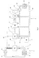
- a fuel cell 3 connected to a power management unit electrical 6 by a power line 60.
- the fuel cell is a battery polymer membrane (PEFC) or alkaline battery (AFC).
- PEFC battery polymer membrane
- AFC alkaline battery
- a electric machine 4 intended to be used as a traction motor or as a generator during the phases of electrical braking.
- the electric machine 4 is connected to at least a driving wheel 40.
- the electronic control module of the electric machine is a inverter 5.
- An electrical line 61 connects the electrical energy management unit 6 to the inverter 5, and an electrical line 62 connects the inverter 5 to the electrical machine 4.
- the traction chain according to the invention preferably comprises a storage device electrical energy, connected to the power line 61 via the management unit 6 of electrical energy, and connected to the electrical energy management unit 6 by means of of an electrical line 63.
- This device for storing electrical energy is advantageously a bank of super capacitors 7.
- the first circuit 1 comprises a first radiator 10 of dissipation of calories to the ambient atmosphere, a hydraulic pump 13, a pipe 12 ensuring the distribution of the coolant from the first radiator 10 to the battery fuel 3.
- the coolant may be a deionized liquid to be conductor of electricity, for example water or a mixture of water and deionized glycol, since it circulates within the fuel cell itself (according to the importance of this electrical aspect, that is, whether it is important to increase the electrical impedance of the branch constituted by this cooling circuit). Meaning Heat transfer fluid circulation is indicated in the drawing.
- hoses 14 returning the coolant after heating from the stack 3 to the first radiator 10 ensuring a heat exchange with the ambient air.
- the cooling of the radiator 10 is made more efficient by the action of a fan 11 ensuring a forced circulation of the ambient air through the radiator 10.
- the second cooling circuit 2 independent of the first circuit 1 and in which circulates a cooling liquid.
- the second cooling circuit 2 uses another independent heat transfer fluid charge the first charge used in the first cooling circuit.
- the cooling circuit is thermally independent of the first circuit of cooling 1: it comprises a second radiator 20 for dissipating calories to the ambient atmosphere, different from the first radiator 10, a hydraulic pump 23 and a network of pipes providing the distribution of coolant to the different organs that must be cooled.
- the direction of circulation of the coolant is indicated on the drawing.
- the second cooling circuit 2 establishes a circulation of coolant in several electrical components.
- the liquid of cooling is for example ordinary water or a mixture of water and glycol.
- the traction chain or even more generally the vehicle propelled by the chain of traction according to the invention could possibly comprise different modules other than the already mentioned inverter 5, the second circuit of cooling 2 establishing a circulation of coolant in several electronic management modules.
- the electronic modules of management cooled by means of a coolant are connected to the second circuit cooling 2.
- all the electrical components cooled by means of a liquid of are connected to this second cooling circuit 2.
- the electric machine 4 mechanically connected to the driving wheel or wheels 40 of the vehicle is connected to this second cooling circuit 2.
- all the electrical components cooled by means of a liquid of cooling are connected to the second cooling circuit 2.
- An electrical dissipation resistor 8 is installed in the first circuit of This dissipation resistor 8 is connected to the electrical line 61 via an electronic switch 81, itself controlled by the energy management unit Electric 6.
- the electric power management unit 6 receives information from the vehicle driver and information describing the operational status of the vehicle, such as the speed of movement. In the electric traction phase, the unit of electrical energy management 6 directly connects the fuel cell 3 to the inverter 5 and the inverter 5 transmit the electrical energy in the form appropriate to the electric machine 4 so that it operates as a motor. Depending on the circumstances, the electric power management unit 6 can also connect the super bench capacitors 7 to the electrical line 61 during the phases of engine operation in order to draw electrical energy in reserve in the bank of super capacitors 7 for add it to the energy from the fuel cell 3.
- Each of the two cooling circuits is preferably temperature controlled, for example by means of a thermostat not shown. Since the circuits are independent, the control temperature of each of these can be different.
- the ideal control temperature for a fuel cell is a little more high that the ideal control temperature of the circuit ensuring the cooling of the electric machine 4 and electronic components associated therewith.
- the control temperature is of the order of 60 ° C to 90 ° C for a battery polymer membrane (PEFC) and it is of the order of 45 ° C to 65 ° C for the circuit ensuring the cooling of the electric machine 4 and the electronic components which are associates.
- PEFC battery polymer membrane
- the inverter 5 drives the machine 4 electric generator so that it returns electrical energy on the line 61. If the electrical energy thus returned on line 61 is greater than the requirements of the vehicle, ie the energy absorbed by the other connected electrical loads in line 61 such as those mentioned above, then piloting the battery to fuel 3 stops the operation of it. Like the inertia of a battery fuel is very low, fuel cell 3 is rapidly ceasing to communicate calories to the coolant circulating in the first circuit of 1. During operation in electric braking, all loads connected to line 61 will absorb some of the electrical energy available. Also, the electrical energy management unit 6 sends the energy electrical priority to the bank of super capacitors 7, in the limit where these have not reached their maximum load.
- the management unit of the electrical energy 6 closes the switch 81 to add the dissipation resistor 8 as electric charge.
- This resistor is able to absorb the maximum current injected on the line 61 by the electrical machine or machines 4.
- the electrical resistance 8 of dissipation heats up and the calories are evacuated as the fluid cooling that takes them to the first radiator 10.
- the installation is dimensioned so that even when the electrical resistance of dissipation 8 is covered by the maximum possible current, the heating of the liquid of cooling inside the cooling circuit 1 remains compatible with the proper operation of the fuel cell 3.
- the efficiency of the evacuation of the calories produced by the dissipation resistor 8 is such as, in comparison with a dissipation resistor which would be cooled in air, we can use resistors 8 much more compact. In addition, there is no degradation of the coefficient of penetration into the vehicle air. Indeed, we use the ability of the radiator 10 to evacuate calories at a time when it would not have been used because of stopping the operation of the fuel cell. Thus, we managed to arrange the cooling circuits so as to make the best use of their capacities and taking advantage of the mutually exclusive character of the operation of the fuel cell its maximum load and the use of dissipation resistor 8 at its expense Max.
Landscapes
- Engineering & Computer Science (AREA)
- Life Sciences & Earth Sciences (AREA)
- Sustainable Development (AREA)
- Sustainable Energy (AREA)
- Power Engineering (AREA)
- Transportation (AREA)
- Mechanical Engineering (AREA)
- Electric Propulsion And Braking For Vehicles (AREA)
- Fuel Cell (AREA)
- Cooling, Air Intake And Gas Exhaust, And Fuel Tank Arrangements In Propulsion Units (AREA)
- Arrangement Or Mounting Of Propulsion Units For Vehicles (AREA)
Applications Claiming Priority (2)
| Application Number | Priority Date | Filing Date | Title |
|---|---|---|---|
| FR0404249 | 2004-04-21 | ||
| FR0404249A FR2869476A1 (fr) | 2004-04-21 | 2004-04-21 | Chaine de traction electrique pour vehicule, comportant une resistance electrique de dissipation refroidie par liquide de refroidissement |
Publications (2)
| Publication Number | Publication Date |
|---|---|
| EP1589601A1 true EP1589601A1 (de) | 2005-10-26 |
| EP1589601B1 EP1589601B1 (de) | 2013-08-21 |
Family
ID=34935275
Family Applications (1)
| Application Number | Title | Priority Date | Filing Date |
|---|---|---|---|
| EP05008360.9A Expired - Lifetime EP1589601B1 (de) | 2004-04-21 | 2005-04-18 | Elektrisches Betriebssystem für ein Fahrzeug, mit dissipativem elektrischem Widerstand gekühlt mit Kühlflussigkeit |
Country Status (5)
| Country | Link |
|---|---|
| US (1) | US7383903B2 (de) |
| EP (1) | EP1589601B1 (de) |
| JP (1) | JP4954493B2 (de) |
| CN (1) | CN100575137C (de) |
| FR (1) | FR2869476A1 (de) |
Cited By (2)
| Publication number | Priority date | Publication date | Assignee | Title |
|---|---|---|---|---|
| CN103532200A (zh) * | 2013-10-25 | 2014-01-22 | 重庆五洲龙新能源汽车有限公司 | 一种新能源汽车的电池管理系统 |
| WO2017084941A1 (fr) * | 2015-11-16 | 2017-05-26 | Bluebus | Systeme de refroidissement pour vehicule electrique, et vehicule electrique muni d'un tel systeme |
Families Citing this family (25)
| Publication number | Priority date | Publication date | Assignee | Title |
|---|---|---|---|---|
| JP4755099B2 (ja) * | 2004-08-18 | 2011-08-24 | 株式会社栗本鐵工所 | 電動車椅子 |
| US7556578B2 (en) * | 2006-10-26 | 2009-07-07 | Gm Global Technology Operations, Inc. | Method and apparatus to control operation of a hydraulic control circuit for an electro-mechanical transmission |
| US20080225483A1 (en) * | 2007-03-15 | 2008-09-18 | Paccar Inc | Frame mounted modular hybrid cooling system |
| JP4461398B2 (ja) * | 2007-12-19 | 2010-05-12 | トヨタ自動車株式会社 | 燃料電池システム |
| US8263279B2 (en) * | 2008-02-20 | 2012-09-11 | GM Global Technology Operations LLC | Apparatus for optimized cooling of a drive unit and a fuel cell in a fuel cell vehicle |
| US8393551B2 (en) * | 2008-07-18 | 2013-03-12 | GM Global Technology Operations LLC | Coolant systems for electric and hybrid-electric vehicles |
| DE102008057118A1 (de) * | 2008-11-13 | 2010-05-20 | Daimler Ag | Brennstoffzellensystem für ein Fahrzeug |
| JP5321910B2 (ja) * | 2009-09-24 | 2013-10-23 | スズキ株式会社 | ハイブリッド車両の冷却装置 |
| JP5417123B2 (ja) * | 2009-10-29 | 2014-02-12 | 株式会社日立製作所 | 電動車両の冷却システム |
| US20110227406A1 (en) * | 2010-03-16 | 2011-09-22 | Nguyen Vietson M | Control method for electrical accumulator unit |
| US8336319B2 (en) * | 2010-06-04 | 2012-12-25 | Tesla Motors, Inc. | Thermal management system with dual mode coolant loops |
| US8427108B2 (en) | 2010-08-19 | 2013-04-23 | Hamilton Sundstrand Corporation | Method for controlling an electric accumulator unit |
| US8461717B2 (en) | 2010-08-19 | 2013-06-11 | Hamilton Sundstrand Corporation | Active filtering electrical accumulator unit |
| US8324869B2 (en) | 2010-08-20 | 2012-12-04 | Hamilton Sundstrand Corporation | Method and apparatus for average current control |
| WO2012033234A1 (ko) * | 2010-09-06 | 2012-03-15 | 볼보 컨스트럭션 이큅먼트 에이비 | 건설기계의 에너지저장소의 방전시스템 |
| DE102010064317A1 (de) * | 2010-12-29 | 2012-07-05 | Robert Bosch Gmbh | System zur Ankopplung mindestens einer Gleichstromquelle an einen steuerbaren Energiespeicher und zugehöriges Betriebsverfahren |
| JP2012183958A (ja) * | 2011-03-07 | 2012-09-27 | Hokuriku Electric Power Co Inc:The | 電気自動車の暖房方法及び装置 |
| JP5790394B2 (ja) * | 2011-10-14 | 2015-10-07 | トヨタ自動車株式会社 | 電気自動車 |
| KR101457937B1 (ko) * | 2012-04-24 | 2014-11-07 | 이청종 | 서버용 유냉식 냉각장치 및 그 구동 방법 |
| US9452682B2 (en) * | 2013-01-18 | 2016-09-27 | GM Global Technology Operations LLC | Transmission for a vehicle |
| DE102013209706B3 (de) * | 2013-05-24 | 2014-11-20 | Siemens Aktiengesellschaft | Kühlanlage zur Kühlung eines Energiespeichers und eines Ladereglers für ein Fahrzeug mit elektrischem Antrieb |
| CN104309469B (zh) * | 2014-05-30 | 2017-03-01 | 潍柴动力股份有限公司 | 一种低温冷却系统、方法及装置 |
| EP3266059A4 (de) * | 2015-12-22 | 2018-10-24 | Hewlett-Packard Enterprise Development LP | Brennstoffzelle für elektronische leistungsbauelemente |
| DE102020128728B4 (de) * | 2020-11-02 | 2022-09-08 | Audi Aktiengesellschaft | Kraftfahrzeug und Verfahren zum Betrieb einer Kühleinrichtung |
| CN218957806U (zh) * | 2022-12-02 | 2023-05-02 | 珠海泰坦新动力电子有限公司 | 一种一体式电池化成设备 |
Citations (3)
| Publication number | Priority date | Publication date | Assignee | Title |
|---|---|---|---|---|
| US5346778A (en) * | 1992-08-13 | 1994-09-13 | Energy Partners, Inc. | Electrochemical load management system for transportation applications |
| WO1996041393A1 (en) * | 1995-06-07 | 1996-12-19 | Ballard Power Systems Inc. | Temperature regulating system for a fuel cell powered vehicle |
| US20030133267A1 (en) * | 2002-01-16 | 2003-07-17 | Beihoff Bruce C. | Cooled electrical terminal assembly and device incorporating same |
Family Cites Families (30)
| Publication number | Priority date | Publication date | Assignee | Title |
|---|---|---|---|---|
| US3626148A (en) | 1969-05-26 | 1971-12-07 | Walter J Woytowich | Electric engine coolant heater |
| US3976507A (en) * | 1975-02-12 | 1976-08-24 | United Technologies Corporation | Pressurized fuel cell power plant with single reactant gas stream |
| JPS6161802A (ja) * | 1984-08-31 | 1986-03-29 | 武田薬品工業株式会社 | 木材保存剤 |
| FR2646500B1 (fr) | 1989-04-27 | 1994-11-25 | Alsthom Gec | Procede de refroidissement de composants electriques, dispositif pour la mise en oeuvre de ce procede et application aux composants embarques dans un vehicule |
| JPH0564378A (ja) * | 1990-11-20 | 1993-03-12 | Mitsubishi Electric Corp | 無停電電源装置 |
| US5255733A (en) * | 1992-08-10 | 1993-10-26 | Ford Motor Company | Hybird vehicle cooling system |
| US5291960A (en) * | 1992-11-30 | 1994-03-08 | Ford Motor Company | Hybrid electric vehicle regenerative braking energy recovery system |
| FR2701435B1 (fr) * | 1993-02-15 | 1995-03-31 | Smh Management Services Ag | Véhicule automobile à traction électrique comprenant un dispositif de récupération d'énergie. |
| DE4322765C1 (de) | 1993-07-08 | 1994-06-16 | Daimler Benz Ag | Verfahren und Vorrichtung zur dynamischen Leistungsregelung für ein Fahrzeug mit Brennstoffzelle |
| DE4327261C1 (de) * | 1993-08-13 | 1994-10-13 | Daimler Benz Ag | Kühlmittelkreislauf |
| US6186254B1 (en) | 1996-05-29 | 2001-02-13 | Xcelliss Fuel Cell Engines Inc. | Temperature regulating system for a fuel cell powered vehicle |
| US6087744A (en) | 1997-08-26 | 2000-07-11 | Robert Bosch Gmbh | Electrical machine |
| FR2792259B1 (fr) * | 1999-04-15 | 2001-06-15 | Valeo Thermique Moteur Sa | Dispositif de refroidissement pour vehicule electrique a pile a combustible |
| EP1072453B1 (de) * | 1999-07-26 | 2006-11-15 | Denso Corporation | Vorrichtung mit einem Kältemittelkreislauf |
| US6394207B1 (en) | 2000-02-16 | 2002-05-28 | General Motors Corporation | Thermal management of fuel cell powered vehicles |
| DE60143647D1 (de) | 2000-10-25 | 2011-01-27 | Michelin Rech Tech | Elektrische drehmaschine und verfahren zur herstellung derselben |
| JP2002184419A (ja) * | 2000-12-14 | 2002-06-28 | Nissan Motor Co Ltd | 燃料電池を搭載した車両の冷却装置 |
| JP3616005B2 (ja) * | 2000-12-20 | 2005-02-02 | 本田技研工業株式会社 | ハイブリッド車両の冷却装置 |
| US6651761B1 (en) * | 2001-09-27 | 2003-11-25 | Ford Global Technologies, Llc | Temperature control system for fuel cell electric vehicle cooling circuit |
| JP3659213B2 (ja) * | 2001-10-30 | 2005-06-15 | 日産自動車株式会社 | 車両用冷却装置 |
| JP2003189409A (ja) | 2001-12-21 | 2003-07-04 | Toyota Motor Corp | 電動機搭載車両 |
| US6838201B2 (en) * | 2002-04-11 | 2005-01-04 | General Motors Corporation | Fuel cell stack coolant conductivity monitoring circuit |
| US6743539B2 (en) * | 2002-04-29 | 2004-06-01 | General Motors Corporation | Coolant fan control for fuel cell systems |
| JP3876793B2 (ja) * | 2002-08-12 | 2007-02-07 | トヨタ自動車株式会社 | 多重冷却システム |
| JP4192535B2 (ja) * | 2002-08-30 | 2008-12-10 | 日産自動車株式会社 | 燃料電池車両 |
| JP3951294B2 (ja) | 2002-09-10 | 2007-08-01 | 住友電気工業株式会社 | モーターの冷却構造 |
| CA2406331C (en) * | 2002-10-01 | 2009-12-22 | Long Manufacturing Ltd. | Thermal management system |
| JP2004268752A (ja) * | 2003-03-10 | 2004-09-30 | Denso Corp | 熱管理システム |
| US7041405B2 (en) * | 2003-10-07 | 2006-05-09 | Utc Fuel Cells, Llc | Fuel cell voltage control |
| EP1588889B1 (de) | 2004-04-21 | 2016-11-23 | MICHELIN Recherche et Technique S.A. | Elektrische Antriebsanlage für Brennstoffzellenfahrzeug mit einem elektrischen Widerstand zur Wärmeabfuhr |
-
2004
- 2004-04-21 FR FR0404249A patent/FR2869476A1/fr active Pending
-
2005
- 2005-04-18 EP EP05008360.9A patent/EP1589601B1/de not_active Expired - Lifetime
- 2005-04-20 US US11/111,258 patent/US7383903B2/en not_active Expired - Fee Related
- 2005-04-21 JP JP2005123097A patent/JP4954493B2/ja not_active Expired - Fee Related
- 2005-04-21 CN CN200510074162A patent/CN100575137C/zh not_active Expired - Fee Related
Patent Citations (3)
| Publication number | Priority date | Publication date | Assignee | Title |
|---|---|---|---|---|
| US5346778A (en) * | 1992-08-13 | 1994-09-13 | Energy Partners, Inc. | Electrochemical load management system for transportation applications |
| WO1996041393A1 (en) * | 1995-06-07 | 1996-12-19 | Ballard Power Systems Inc. | Temperature regulating system for a fuel cell powered vehicle |
| US20030133267A1 (en) * | 2002-01-16 | 2003-07-17 | Beihoff Bruce C. | Cooled electrical terminal assembly and device incorporating same |
Cited By (3)
| Publication number | Priority date | Publication date | Assignee | Title |
|---|---|---|---|---|
| CN103532200A (zh) * | 2013-10-25 | 2014-01-22 | 重庆五洲龙新能源汽车有限公司 | 一种新能源汽车的电池管理系统 |
| CN103532200B (zh) * | 2013-10-25 | 2016-04-13 | 重庆五洲龙新能源汽车有限公司 | 一种新能源汽车的电池管理系统 |
| WO2017084941A1 (fr) * | 2015-11-16 | 2017-05-26 | Bluebus | Systeme de refroidissement pour vehicule electrique, et vehicule electrique muni d'un tel systeme |
Also Published As
| Publication number | Publication date |
|---|---|
| JP2005335680A (ja) | 2005-12-08 |
| CN100575137C (zh) | 2009-12-30 |
| JP4954493B2 (ja) | 2012-06-13 |
| US20050244691A1 (en) | 2005-11-03 |
| US7383903B2 (en) | 2008-06-10 |
| FR2869476A1 (fr) | 2005-10-28 |
| EP1589601B1 (de) | 2013-08-21 |
| CN1689857A (zh) | 2005-11-02 |
Similar Documents
| Publication | Publication Date | Title |
|---|---|---|
| EP1589601B1 (de) | Elektrisches Betriebssystem für ein Fahrzeug, mit dissipativem elektrischem Widerstand gekühlt mit Kühlflussigkeit | |
| EP1588889B1 (de) | Elektrische Antriebsanlage für Brennstoffzellenfahrzeug mit einem elektrischen Widerstand zur Wärmeabfuhr | |
| EP1241041B1 (de) | Fahrzeug mit Super-Kondensator zur Bremsenergie-Rückgewinnung | |
| EP3017498B1 (de) | Thermische steuervorrichtung der batterie eines elektrofahrzeugs | |
| EP2044646B1 (de) | Kompakte energieversorgungsvorrichtung für ein kraftfahrzeug mit geregelter kühlvorrichtung | |
| CA2430157A1 (fr) | Systeme de traction pour vehicule electrique | |
| EP4100268B1 (de) | Vorrichtung zur rückgewinnung und regulierung von wärmeenergie eines elektrofahrzeugs mit elektrochemischem generator und hlkk-system | |
| FR3063188A1 (fr) | Batterie a groupes de cellule(s) de stockage associes respectivement a des modules de conversion, pour la fourniture de tensions de types differents | |
| FR2994546A1 (fr) | Procede de limitation de couple d'une machine electrique de vehicule hybride comportant un systeme de controle de vitesse | |
| EP2512893A1 (de) | Verfahren zur steuerung eines antriebsaggregats eines hybridfahrzeugs und zugehörige vorrichtung | |
| EP2616260B1 (de) | Antriebsstrang für ein hybridfahrzeug | |
| WO2022180310A1 (fr) | Procede et dispositif de controle d'une batterie evitant un emballement thermique | |
| FR2842144A1 (fr) | Procede et dispositif de transmission de puissance pour une vehicule automobile comprenant un moteur thermique et au moins une machine electrique | |
| WO2012131235A2 (fr) | Procede et systeme d'alimentation electrique redondante d'un vehicule automobile hybride | |
| CH717116A2 (fr) | Dispositif de récupération et de régulation d'énergie thermique d'un véhicule électrique à générateur électrochimique avec un système HVAC. | |
| FR3113338A1 (fr) | Dispositif d’alimentation de cathode d’une pile à combustible en air sous pression, à refroidissement optimisé | |
| FR2967634A1 (fr) | Procede de gestion, en fonction de la charge transportee, du fonctionnement d'un vehicule hybride de type vehicule de transport de charges lourdes | |
| WO2025151090A1 (fr) | Voiture électrique chargée par l'énergie généré du mouvement des roues | |
| FR3136410A3 (fr) | Véhicule hybride comprenant un système de motorisation électrique et un système de refroidissement | |
| FR2884887A1 (fr) | Systeme de transmission d'energie cinetique | |
| FR3144566A1 (fr) | Ensemble pour vehicule comprenant un dispositif de stockage d’energie electrique et au moins un element de refroidissement d’un fluide caloporteur | |
| FR3022496A1 (fr) | Systeme de propulsion pour vehicule automobile hybride comprenant des moyens de recuperation de l'energie thermique perdue | |
| FR3142707A1 (fr) | Groupe motopropulseur à hydrogène et procédé de commande de ce groupe | |
| FR3152927A1 (fr) | Véhicule comprenant un système de refroidissement et de maintien en température d’une pile à combustible | |
| FR2930748A1 (fr) | Procede et dispositif de controle d'un stockeur d'energie pour vehicule hybride |
Legal Events
| Date | Code | Title | Description |
|---|---|---|---|
| PUAI | Public reference made under article 153(3) epc to a published international application that has entered the european phase |
Free format text: ORIGINAL CODE: 0009012 |
|
| AK | Designated contracting states |
Kind code of ref document: A1 Designated state(s): AT BE BG CH CY CZ DE DK EE ES FI FR GB GR HU IE IS IT LI LT LU MC NL PL PT RO SE SI SK TR |
|
| AX | Request for extension of the european patent |
Extension state: AL BA HR LV MK YU |
|
| 17P | Request for examination filed |
Effective date: 20060426 |
|
| AKX | Designation fees paid |
Designated state(s): AT BE BG CH CY CZ DE DK EE ES FI FR GB GR HU IE IS IT LI LT LU MC NL PL PT RO SE SI SK TR |
|
| RAP1 | Party data changed (applicant data changed or rights of an application transferred) |
Owner name: PAUL SCHERRER INSTITUT Owner name: MICHELIN RECHERCHE ET TECHNIQUE S.A. |
|
| REG | Reference to a national code |
Ref country code: DE Ref legal event code: R079 Ref document number: 602005040924 Country of ref document: DE Free format text: PREVIOUS MAIN CLASS: H01M0008040000 Ipc: B60L0011180000 |
|
| GRAP | Despatch of communication of intention to grant a patent |
Free format text: ORIGINAL CODE: EPIDOSNIGR1 |
|
| RIC1 | Information provided on ipc code assigned before grant |
Ipc: B60L 11/18 20060101AFI20130313BHEP |
|
| INTG | Intention to grant announced |
Effective date: 20130409 |
|
| GRAS | Grant fee paid |
Free format text: ORIGINAL CODE: EPIDOSNIGR3 |
|
| GRAA | (expected) grant |
Free format text: ORIGINAL CODE: 0009210 |
|
| AK | Designated contracting states |
Kind code of ref document: B1 Designated state(s): AT BE BG CH CY CZ DE DK EE ES FI FR GB GR HU IE IS IT LI LT LU MC NL PL PT RO SE SI SK TR |
|
| REG | Reference to a national code |
Ref country code: GB Ref legal event code: FG4D Free format text: NOT ENGLISH |
|
| REG | Reference to a national code |
Ref country code: CH Ref legal event code: EP |
|
| REG | Reference to a national code |
Ref country code: AT Ref legal event code: REF Ref document number: 627839 Country of ref document: AT Kind code of ref document: T Effective date: 20130915 |
|
| REG | Reference to a national code |
Ref country code: IE Ref legal event code: FG4D Free format text: LANGUAGE OF EP DOCUMENT: FRENCH |
|
| REG | Reference to a national code |
Ref country code: DE Ref legal event code: R096 Ref document number: 602005040924 Country of ref document: DE Effective date: 20131017 |
|
| REG | Reference to a national code |
Ref country code: AT Ref legal event code: MK05 Ref document number: 627839 Country of ref document: AT Kind code of ref document: T Effective date: 20130821 Ref country code: NL Ref legal event code: VDEP Effective date: 20130821 |
|
| REG | Reference to a national code |
Ref country code: LT Ref legal event code: MG4D |
|
| PG25 | Lapsed in a contracting state [announced via postgrant information from national office to epo] |
Ref country code: SE Free format text: LAPSE BECAUSE OF FAILURE TO SUBMIT A TRANSLATION OF THE DESCRIPTION OR TO PAY THE FEE WITHIN THE PRESCRIBED TIME-LIMIT Effective date: 20130821 Ref country code: AT Free format text: LAPSE BECAUSE OF FAILURE TO SUBMIT A TRANSLATION OF THE DESCRIPTION OR TO PAY THE FEE WITHIN THE PRESCRIBED TIME-LIMIT Effective date: 20130821 Ref country code: IS Free format text: LAPSE BECAUSE OF FAILURE TO SUBMIT A TRANSLATION OF THE DESCRIPTION OR TO PAY THE FEE WITHIN THE PRESCRIBED TIME-LIMIT Effective date: 20131221 Ref country code: PT Free format text: LAPSE BECAUSE OF FAILURE TO SUBMIT A TRANSLATION OF THE DESCRIPTION OR TO PAY THE FEE WITHIN THE PRESCRIBED TIME-LIMIT Effective date: 20131223 Ref country code: LT Free format text: LAPSE BECAUSE OF FAILURE TO SUBMIT A TRANSLATION OF THE DESCRIPTION OR TO PAY THE FEE WITHIN THE PRESCRIBED TIME-LIMIT Effective date: 20130821 Ref country code: CY Free format text: LAPSE BECAUSE OF FAILURE TO SUBMIT A TRANSLATION OF THE DESCRIPTION OR TO PAY THE FEE WITHIN THE PRESCRIBED TIME-LIMIT Effective date: 20130619 |
|
| PG25 | Lapsed in a contracting state [announced via postgrant information from national office to epo] |
Ref country code: FI Free format text: LAPSE BECAUSE OF FAILURE TO SUBMIT A TRANSLATION OF THE DESCRIPTION OR TO PAY THE FEE WITHIN THE PRESCRIBED TIME-LIMIT Effective date: 20130821 Ref country code: SI Free format text: LAPSE BECAUSE OF FAILURE TO SUBMIT A TRANSLATION OF THE DESCRIPTION OR TO PAY THE FEE WITHIN THE PRESCRIBED TIME-LIMIT Effective date: 20130821 Ref country code: GR Free format text: LAPSE BECAUSE OF FAILURE TO SUBMIT A TRANSLATION OF THE DESCRIPTION OR TO PAY THE FEE WITHIN THE PRESCRIBED TIME-LIMIT Effective date: 20131122 Ref country code: PL Free format text: LAPSE BECAUSE OF FAILURE TO SUBMIT A TRANSLATION OF THE DESCRIPTION OR TO PAY THE FEE WITHIN THE PRESCRIBED TIME-LIMIT Effective date: 20130821 |
|
| PG25 | Lapsed in a contracting state [announced via postgrant information from national office to epo] |
Ref country code: CY Free format text: LAPSE BECAUSE OF FAILURE TO SUBMIT A TRANSLATION OF THE DESCRIPTION OR TO PAY THE FEE WITHIN THE PRESCRIBED TIME-LIMIT Effective date: 20130821 |
|
| PG25 | Lapsed in a contracting state [announced via postgrant information from national office to epo] |
Ref country code: EE Free format text: LAPSE BECAUSE OF FAILURE TO SUBMIT A TRANSLATION OF THE DESCRIPTION OR TO PAY THE FEE WITHIN THE PRESCRIBED TIME-LIMIT Effective date: 20130821 Ref country code: SK Free format text: LAPSE BECAUSE OF FAILURE TO SUBMIT A TRANSLATION OF THE DESCRIPTION OR TO PAY THE FEE WITHIN THE PRESCRIBED TIME-LIMIT Effective date: 20130821 Ref country code: DK Free format text: LAPSE BECAUSE OF FAILURE TO SUBMIT A TRANSLATION OF THE DESCRIPTION OR TO PAY THE FEE WITHIN THE PRESCRIBED TIME-LIMIT Effective date: 20130821 Ref country code: NL Free format text: LAPSE BECAUSE OF FAILURE TO SUBMIT A TRANSLATION OF THE DESCRIPTION OR TO PAY THE FEE WITHIN THE PRESCRIBED TIME-LIMIT Effective date: 20130821 Ref country code: CZ Free format text: LAPSE BECAUSE OF FAILURE TO SUBMIT A TRANSLATION OF THE DESCRIPTION OR TO PAY THE FEE WITHIN THE PRESCRIBED TIME-LIMIT Effective date: 20130821 Ref country code: RO Free format text: LAPSE BECAUSE OF FAILURE TO SUBMIT A TRANSLATION OF THE DESCRIPTION OR TO PAY THE FEE WITHIN THE PRESCRIBED TIME-LIMIT Effective date: 20130821 |
|
| PGFP | Annual fee paid to national office [announced via postgrant information from national office to epo] |
Ref country code: CH Payment date: 20140328 Year of fee payment: 10 |
|
| PG25 | Lapsed in a contracting state [announced via postgrant information from national office to epo] |
Ref country code: ES Free format text: LAPSE BECAUSE OF FAILURE TO SUBMIT A TRANSLATION OF THE DESCRIPTION OR TO PAY THE FEE WITHIN THE PRESCRIBED TIME-LIMIT Effective date: 20130821 |
|
| PLBE | No opposition filed within time limit |
Free format text: ORIGINAL CODE: 0009261 |
|
| STAA | Information on the status of an ep patent application or granted ep patent |
Free format text: STATUS: NO OPPOSITION FILED WITHIN TIME LIMIT |
|
| 26N | No opposition filed |
Effective date: 20140522 |
|
| REG | Reference to a national code |
Ref country code: DE Ref legal event code: R097 Ref document number: 602005040924 Country of ref document: DE Effective date: 20140522 |
|
| PG25 | Lapsed in a contracting state [announced via postgrant information from national office to epo] |
Ref country code: LU Free format text: LAPSE BECAUSE OF FAILURE TO SUBMIT A TRANSLATION OF THE DESCRIPTION OR TO PAY THE FEE WITHIN THE PRESCRIBED TIME-LIMIT Effective date: 20140418 Ref country code: MC Free format text: LAPSE BECAUSE OF FAILURE TO SUBMIT A TRANSLATION OF THE DESCRIPTION OR TO PAY THE FEE WITHIN THE PRESCRIBED TIME-LIMIT Effective date: 20130821 |
|
| REG | Reference to a national code |
Ref country code: IE Ref legal event code: MM4A |
|
| PG25 | Lapsed in a contracting state [announced via postgrant information from national office to epo] |
Ref country code: IE Free format text: LAPSE BECAUSE OF NON-PAYMENT OF DUE FEES Effective date: 20140418 |
|
| REG | Reference to a national code |
Ref country code: CH Ref legal event code: PL |
|
| PG25 | Lapsed in a contracting state [announced via postgrant information from national office to epo] |
Ref country code: LI Free format text: LAPSE BECAUSE OF NON-PAYMENT OF DUE FEES Effective date: 20150430 Ref country code: CH Free format text: LAPSE BECAUSE OF NON-PAYMENT OF DUE FEES Effective date: 20150430 |
|
| REG | Reference to a national code |
Ref country code: FR Ref legal event code: PLFP Year of fee payment: 12 |
|
| PG25 | Lapsed in a contracting state [announced via postgrant information from national office to epo] |
Ref country code: BG Free format text: LAPSE BECAUSE OF FAILURE TO SUBMIT A TRANSLATION OF THE DESCRIPTION OR TO PAY THE FEE WITHIN THE PRESCRIBED TIME-LIMIT Effective date: 20130821 |
|
| PG25 | Lapsed in a contracting state [announced via postgrant information from national office to epo] |
Ref country code: HU Free format text: LAPSE BECAUSE OF FAILURE TO SUBMIT A TRANSLATION OF THE DESCRIPTION OR TO PAY THE FEE WITHIN THE PRESCRIBED TIME-LIMIT; INVALID AB INITIO Effective date: 20050418 Ref country code: BE Free format text: LAPSE BECAUSE OF FAILURE TO SUBMIT A TRANSLATION OF THE DESCRIPTION OR TO PAY THE FEE WITHIN THE PRESCRIBED TIME-LIMIT Effective date: 20140430 Ref country code: TR Free format text: LAPSE BECAUSE OF FAILURE TO SUBMIT A TRANSLATION OF THE DESCRIPTION OR TO PAY THE FEE WITHIN THE PRESCRIBED TIME-LIMIT Effective date: 20130821 |
|
| REG | Reference to a national code |
Ref country code: FR Ref legal event code: PLFP Year of fee payment: 13 |
|
| PGFP | Annual fee paid to national office [announced via postgrant information from national office to epo] |
Ref country code: FR Payment date: 20170419 Year of fee payment: 13 Ref country code: DE Payment date: 20170419 Year of fee payment: 13 Ref country code: GB Payment date: 20170419 Year of fee payment: 13 |
|
| PGFP | Annual fee paid to national office [announced via postgrant information from national office to epo] |
Ref country code: IT Payment date: 20170424 Year of fee payment: 13 |
|
| REG | Reference to a national code |
Ref country code: DE Ref legal event code: R119 Ref document number: 602005040924 Country of ref document: DE |
|
| GBPC | Gb: european patent ceased through non-payment of renewal fee |
Effective date: 20180418 |
|
| PG25 | Lapsed in a contracting state [announced via postgrant information from national office to epo] |
Ref country code: DE Free format text: LAPSE BECAUSE OF NON-PAYMENT OF DUE FEES Effective date: 20181101 |
|
| PG25 | Lapsed in a contracting state [announced via postgrant information from national office to epo] |
Ref country code: GB Free format text: LAPSE BECAUSE OF NON-PAYMENT OF DUE FEES Effective date: 20180418 |
|
| PG25 | Lapsed in a contracting state [announced via postgrant information from national office to epo] |
Ref country code: IT Free format text: LAPSE BECAUSE OF NON-PAYMENT OF DUE FEES Effective date: 20180418 Ref country code: FR Free format text: LAPSE BECAUSE OF NON-PAYMENT OF DUE FEES Effective date: 20180430 |