US6087744A - Electrical machine - Google Patents
Electrical machine Download PDFInfo
- Publication number
- US6087744A US6087744A US09/131,830 US13183098A US6087744A US 6087744 A US6087744 A US 6087744A US 13183098 A US13183098 A US 13183098A US 6087744 A US6087744 A US 6087744A
- Authority
- US
- United States
- Prior art keywords
- rotor
- electrical machine
- air
- housing
- internal combustion
- Prior art date
- Legal status (The legal status is an assumption and is not a legal conclusion. Google has not performed a legal analysis and makes no representation as to the accuracy of the status listed.)
- Expired - Lifetime
Links
Images


Classifications
-
- H—ELECTRICITY
- H02—GENERATION; CONVERSION OR DISTRIBUTION OF ELECTRIC POWER
- H02K—DYNAMO-ELECTRIC MACHINES
- H02K1/00—Details of the magnetic circuit
- H02K1/06—Details of the magnetic circuit characterised by the shape, form or construction
- H02K1/22—Rotating parts of the magnetic circuit
- H02K1/32—Rotating parts of the magnetic circuit with channels or ducts for flow of cooling medium
-
- H—ELECTRICITY
- H02—GENERATION; CONVERSION OR DISTRIBUTION OF ELECTRIC POWER
- H02K—DYNAMO-ELECTRIC MACHINES
- H02K5/00—Casings; Enclosures; Supports
- H02K5/04—Casings or enclosures characterised by the shape, form or construction thereof
- H02K5/20—Casings or enclosures characterised by the shape, form or construction thereof with channels or ducts for flow of cooling medium
- H02K5/203—Casings or enclosures characterised by the shape, form or construction thereof with channels or ducts for flow of cooling medium specially adapted for liquids, e.g. cooling jackets
-
- H—ELECTRICITY
- H02—GENERATION; CONVERSION OR DISTRIBUTION OF ELECTRIC POWER
- H02K—DYNAMO-ELECTRIC MACHINES
- H02K5/00—Casings; Enclosures; Supports
- H02K5/04—Casings or enclosures characterised by the shape, form or construction thereof
- H02K5/20—Casings or enclosures characterised by the shape, form or construction thereof with channels or ducts for flow of cooling medium
- H02K5/207—Casings or enclosures characterised by the shape, form or construction thereof with channels or ducts for flow of cooling medium with openings in the casing specially adapted for ambient air
-
- H—ELECTRICITY
- H02—GENERATION; CONVERSION OR DISTRIBUTION OF ELECTRIC POWER
- H02K—DYNAMO-ELECTRIC MACHINES
- H02K9/00—Arrangements for cooling or ventilating
- H02K9/02—Arrangements for cooling or ventilating by ambient air flowing through the machine
- H02K9/04—Arrangements for cooling or ventilating by ambient air flowing through the machine having means for generating a flow of cooling medium
- H02K9/06—Arrangements for cooling or ventilating by ambient air flowing through the machine having means for generating a flow of cooling medium with fans or impellers driven by the machine shaft
Definitions
- the present invention relates to electrical machines.
- so-called compact generators which have two flow ventilations by means of two small inwardly located fans.
- the cooling air is aspirated axially and leaves the generator radially in the region of its stator winding head in a drive and collector ring shield.
- additional devices for fresh air aspiration are known.
- the intensity of the cooling must be designed so that the temperature of the components of the generator do not exceed specific limits under all occurring border conditions.
- Conventional complete encapsulation against dust, dirt, and spraying water in utility vehicle generators increases the problems of the required heat withdrawal.
- closed generators are known with cooling ribs for surface cooling, as well close generator with liquid cooling, for example oil.
- cooling circulations which are independent from one another can be varied with respect to their volumes streams and optimized.
- the cooling circulation when operational temperature of the electrical machine is reached, can be switched off individually and independently from one another.
- the stator has a cooling jacket which is joined with an inner surface in a substantially cylindrical housing of the electrical machine and has at least one ring-shaped cooling passage.
- several cooling passages can be provided in the cooling jacket which for example are connected with one another by passages and/or separated from one another by webs.
- the inventive so-called hybrid cooling of the electrical machine can be coupled in an advantageous manner with a liquid cooling circulation of the internal combustion engine.
- a separating valve which is operating electrically or in another manner can be provided.
- a cooling circulation for electrical machines which is independent from the cooling circulation of the internal combustion engine.
- mechanically or electrically operated pump can be used for circulation of the cooling liquid.
- the circulation can be also performed by heating, or in other words in accordance with the thermo siphone principle. For this purpose no special pump is needed.
- the cooling circulation of the rotor of the electrical machine is operated for example with air as a cooling medium, since no insulation problems with respect to flow-guiding components must be taken into consideration.
- the rotor has a central opening, through which the air can flow, and also several transverse openings through which the air can flow radially outwardly and circulate through several openings in the electrical machine.
- the design of the air-guiding element can provide a suction action of the circulating air, which is supported by a central positive guiding element which closes the hollow openings of the rotor. Furthermore, it can be advantageous when an impulse wheel or an impeller with several vanes is provided, which supports the air circulation as a further positive guiding element (air guiding plate turbine). It is advantageous when the airflow passes over a winding head of the electrical machine and thereby can be used especially at high rotary speed for an effective cooling.
- a cooling of air which passes through the water-cooled housing is guaranteed by corresponding air guides, and thereby an effective heat exchange of the cooling media with one another is obtained.
- the air circulation can be both closed, or partially or completely open, or in other words provided with permanent air supply from outside. In an open air circulation, it is advantageous to provide withdrawal of wear products of the friction coating of a dry coupling of the motor vehicle.
- the openings located in the housing for the flowing out air can be both arranged at an end side axially as well as also at the peripheral side radially. In a preferable modification of the invention, all or several openings can be guided in the housing also as longitudinal openings, such as slots or longitudinal slots.
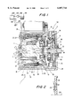
- FIG. 1 is a view showing the schematic section of an electrical machine operatively connected with a transmission
- FIG. 2 is a section of a part of the machine shown in FIG. 1;
- FIG. 3 is a schematic section of a modified embodiment of the electrical machine of FIG. 1.
- FIG. 4 is a perspective view of a cooling jacket of the inventive electrical machine
- FIG. 5 is a view showing the cooling jacket in accordance with another embodiment of the present invention.
- FIG. 6 is a view showing the cooling jacket in accordance with still a further embodiment of the present invention.
- FIG. 7 is a view showing a further embodiment of the electrical machine in accordance with the present invention.
- FIG. 1 shows a schematic cross-section of an electrical machine 1.
- the Figure schematically shows an internal combustion engine 100, a radiator 101, and two conduits 102, 103 for feeding fluid from the engine 10 in the radiator 101 and back again. Cooling fluid for the electrical machine 1 is tapped form the conduit 103 by a tube 104 and fed back to a pump 106 by a tube 105.
- the electrical machine 1 is operatively connected with a transmission.
- the transmission in a shown embodiment is a planetary transmission 52.
- the reduction ratio of the electrical machine 1 relative to a drive train of a motor vehicle is varied in two stages.
- the electrical machine 1 in the shown embodiment a three phase electrical machine. It has a stator 34 with two winding heads 10 and 18 and a rotor 44 which is inoperative connection with the planetary transmission 52.
- the stator 34 is surrounded by a cooling jacket 40.
- the cooling jacket 4 which is substantially cylindrical is connected with an inner surface 45 of a substantially cylindrical housing 36.
- the cooling jacket 40 has one or several ring-shaped or meander-shaped grooves which operate as cooling passages 38. Due to the resulting great contacting surface of the cooling jacket 40 with the housing 30, a good heat transfer from the stator 34 to the cooling jacket 40 and thereby to the housing 36 is guaranteed. During rinsing of the cooling passage 38 with a cooling medium 32, for example with water, a good heat withdrawal is obtained. The substantial heat generation produced in the electrical machine 1 during operation with high load can be transferred from the stator 34 to the housing 36 and then withdrawn fast by the cooling medium 32.
- the cooling medium 32 can enter through a not shown inlet opening in the ring-shaped or meander-shaped cooling passage 38, and then flow through it through the whole periphery of the cooling jacket 40.
- the cooling medium 32 takes a heat energy and can exit through a not shown outlet opening. Because of the large-surface connection and a good thermal transition between the stator 34 and the cooling jacket 40, the stator 34 and thereby the electrical machine 1 are cooled very effectively.
- the heat transfer between the stator 34 and the cooling jacket 40 can be further improved by a good throughflow with the cooling medium 32, which can be obtained by branching into several cooling passages, for example by a web.
- the cooling medium 32 can be circulated by a separate pump provided for this purpose. It is also possible to conduct a circulation based on a thermosiphon principle so that no separate pump is needed.
- connection to the cooling system in particular the cooling circulation of the internal combustion engine is provided. It should be mentioned that with an operational temperature of the internal combustion engine, the temperatures in the cooling medium 32 are substantially higher than in the case of the separate cooling circulation.
- the rotor 44 is rotatably supported in two ball bearings which together with a claw pole 46 and two windings heads 10 and 18 form the electrical machine 1. It further can be seen that the shaft end of the rotor 44 which is located at the right side in FIG. 1 is formed as a central sun gear 66 for a planetary transmission 52 provided with a plurality of planetary gears 68.
- the planetary gears are rotatably supported on a planetary carrier 71 which, together with driven shafts 72 of the planetary transmission 52 form a structural assembly.
- the planetary gears 68 engage with a hollow gear 70 which is fixed relative to the housing 36 or relative the planetary carrier 71. Thereby both particles reduction stages of the planetary transmission can be produced.
- the rotor 44 is provided with a central opening 2 at the left shaft end in FIG. 1.
- the central opening 2 opens into a hollow opening 4 of a greater diameter and provides a throughflow with cooling air.
- the air which flows in the opening 2 flows through the rotor 44 through the hollow opening 4 over its whole length and can flow out through at least two transverse openings 6 directly outside of the right ball bearing 60, radially outwardly into a supply chamber 54 between the transmission 52 and the electrical machine 1.
- the at least two, preferably more, transfers opening 6 are arranged not exactly perpendicular to the rotary axis 56 of the rotor 44. Instead for better air guidance they are slightly inclined outwardly in direction of the shaft end of the rotor 44.
- the transverse openings performs simultaneously the function of a turbine, with the peripheral speed of the outer diameter greater than the peripheral speed at the inner diameter. For this purpose, thereby a suction, in particular a negative pressure, can be obtained, which transports the air from the core of the rotor 44 or in other words from the hollow opening 4.
- This action is supported by an angularly shaped positive guiding element.
- it is formed by a conical closing plug 8 whose conical tip 9 coincides with the rotary axis 56 of the rotor 44.
- the closing plug 8 closes thereby the hollow opening 4 at the side of the rotor 44 which is opposite to the opening 2, and forces the air which flows in the opening 2 to flow out through the transverse openings 6.
- the air which is located in the supply chamber 54 is further guided through several openings 14 or a longitudinal slots 15, which guide the air in direction of an air gap between the rotor 44 and the stator 34.
- the air passes over the winding head 10 at the drive side and can take the heat. Simultaneously, it is cooled by passing over the water-cooled housing 46, before it is guided through the air gap between the rotor 44 and the stator 34, as well as through the claw pole 46 and an excitation winding 16 toward the winding head 18. Therefore the above mentioned elements are cooled.
- the air passes the water-cooled housing 36, it takes the heat with it and is cooled.
- the air can flow out from the electrical machine 1 through several openings 22 or longitudinal slots 23 arranged at the end side of the housing 36. A part of the flowing out air is again aspirated trough the opening 2 as a fresh air. Thereby a partially closed circulation is produced.
- FIG. 2 shows an impulse wheel 28 or an impeller in a detailed cross-section corresponding to FIG. 1. It is formed as a flat disk and fixed immediately adjoining the outflow openings in the radial transverse openings 6 on the shaft in the rotor 44. Thereby the deviation of the airflow from the transverse openings 6 into the openings 14 or into the slot 15 is supported. It flows from a direction coaxial to the rotary axis 56, to a passing flow on the air gap between the rotor 44 and the stator 34 with a deviation around 180°.
- the impulse wheel 28 has several vanes 26 provided on a flat side which faces the electrical machine 1. It also has an air guiding plate 30 located perpendicular to its end.
- the ring-shaped air guiding plate 30 with a contour curved at the inner and outer edges of the ring is located with its flat side parallel to the flat side of the impulse wheel 26 or perpendicular to the rotary axis 56.
- the impulse wheel acts together with the vanes 26 and the air guiding plate 30 as a turbine and operates for supporting the suction action of the air from the transverse openings 6.
- FIG. 3 shows a further cross-section of a modified embodiment of the hybrid-cooled electrical machine 1.
- the parts which are similar to the parts of the previous figures are identified with the same reference numerals and not illustrated in detail.
- a cover 48 is provided at the end side at the left on the housing 36, or in other words at the same side as the opening 2.
- the cover 48 prevents the flow out of the air outwardly and thereby serves for a closed circulation of the air.
- the air which exits the openings 22 or the longitudinal slots 23 can enter the opening 2 again. A greater part of the heat which is taken by the cooling air is transported through the liquid cooling medium 32 outwardly.
- FIG. 4 is a perspective view of the cooling jacket which substantially corresponds to the cooling jacket 40, and has a meander-shaped cooling passage 18'.
- FIG. 5 shows a cooling jacket which has a spiral-shaped cooling passage 18".
- the cooling passage extends twice around the circumference of the jacket.
- FIG. 6 shows a cooling jacket having a plurality of cooling passages 18'" separated from one another by webs.
- FIG. 7 shows an embodiment, in which the slots 110 of means for providing separate circulations with different cooling mediums for the stator and the rotor are replaced by peripheral openings 111.
Abstract
An electrical machine for starting an internal combustion engine and/or for voltage supply of a vehicle electrical system of a motor vehicle has a housing, a stator mounted on the housing, a claw pole rotor system, a separable operative connection with an internal combustion engine, and separate circulations with different cooling media for the stator and the rotor.
Description
The present invention relates to electrical machines.
It is known to use electrical machines, in particular three phase current generators for energy supply of a vehicle electrical system in motor vehicles. Claw pole generators are used for this purpose. They are very light and powerful and therefore are cost favorable. Embodiments with a single flow axial ventilation by an outwardly located fans are known.
In addition, so-called compact generators are used, which have two flow ventilations by means of two small inwardly located fans. The cooling air is aspirated axially and leaves the generator radially in the region of its stator winding head in a drive and collector ring shield. In order to guarantee an effective generator cooling in the case of high motor chamber temperatures, additional devices for fresh air aspiration are known.
The intensity of the cooling must be designed so that the temperature of the components of the generator do not exceed specific limits under all occurring border conditions. Conventional complete encapsulation against dust, dirt, and spraying water in utility vehicle generators increases the problems of the required heat withdrawal. Furthermore, closed generators are known with cooling ribs for surface cooling, as well close generator with liquid cooling, for example oil.
Accordingly, it is an object of present invention to provide an electrical machine, which, due to separate cooling circulation for a stator and for a rotor makes possible an independent cooling of the component.
In particular with the use of different cooling media for stator and rotor, for example water and air, an independent cooling as well as an optimization of a preferable cooling medium passage with respect to a temperature load can be provided. The cooling circulations which are independent from one another can be varied with respect to their volumes streams and optimized.
In accordance with a preferable embodiment of the invention, the cooling circulation, when operational temperature of the electrical machine is reached, can be switched off individually and independently from one another. It is advantageous when the stator has a cooling jacket which is joined with an inner surface in a substantially cylindrical housing of the electrical machine and has at least one ring-shaped cooling passage. In order to guarantee a large-surface and effective cooling, it is however advantageous to extend the cooling passage over a great surface of the cooling jacket, for example meander-or spiral shaped in a peripheral direction of the housing. Also, several cooling passages can be provided in the cooling jacket which for example are connected with one another by passages and/or separated from one another by webs.
The inventive so-called hybrid cooling of the electrical machine can be coupled in an advantageous manner with a liquid cooling circulation of the internal combustion engine. Preferably, a separating valve which is operating electrically or in another manner can be provided. It is also possible to provide a cooling circulation for electrical machines which is independent from the cooling circulation of the internal combustion engine. For circulation of the cooling liquid, mechanically or electrically operated pump can be used. The circulation can be also performed by heating, or in other words in accordance with the thermo siphone principle. For this purpose no special pump is needed.
The cooling circulation of the rotor of the electrical machine is operated for example with air as a cooling medium, since no insulation problems with respect to flow-guiding components must be taken into consideration. In a preferable embodiment, the rotor has a central opening, through which the air can flow, and also several transverse openings through which the air can flow radially outwardly and circulate through several openings in the electrical machine.
In accordance with an especially advantageous embodiment of the present invention, the design of the air-guiding element can provide a suction action of the circulating air, which is supported by a central positive guiding element which closes the hollow openings of the rotor. Furthermore, it can be advantageous when an impulse wheel or an impeller with several vanes is provided, which supports the air circulation as a further positive guiding element (air guiding plate turbine). It is advantageous when the airflow passes over a winding head of the electrical machine and thereby can be used especially at high rotary speed for an effective cooling.
In a preferable embodiment, a cooling of air which passes through the water-cooled housing is guaranteed by corresponding air guides, and thereby an effective heat exchange of the cooling media with one another is obtained. The air circulation can be both closed, or partially or completely open, or in other words provided with permanent air supply from outside. In an open air circulation, it is advantageous to provide withdrawal of wear products of the friction coating of a dry coupling of the motor vehicle. The openings located in the housing for the flowing out air can be both arranged at an end side axially as well as also at the peripheral side radially. In a preferable modification of the invention, all or several openings can be guided in the housing also as longitudinal openings, such as slots or longitudinal slots.
The novel features which are considered as characteristic for the present invention are set forth in particular in the appended claims. The invention itself, however, both as to its construction and its method of operation, together with additional objects and advantages thereof, will be best understood from the following description of specific embodiments when read in connection with the accompanying drawings.
FIG. 1 is a view showing the schematic section of an electrical machine operatively connected with a transmission;
FIG. 2 is a section of a part of the machine shown in FIG. 1;
FIG. 3 is a schematic section of a modified embodiment of the electrical machine of FIG. 1.
FIG. 4 is a perspective view of a cooling jacket of the inventive electrical machine;
FIG. 5 is a view showing the cooling jacket in accordance with another embodiment of the present invention;
FIG. 6 is a view showing the cooling jacket in accordance with still a further embodiment of the present invention; and
FIG. 7 is a view showing a further embodiment of the electrical machine in accordance with the present invention.
FIG. 1 shows a schematic cross-section of an electrical machine 1. The Figure schematically shows an internal combustion engine 100, a radiator 101, and two conduits 102, 103 for feeding fluid from the engine 10 in the radiator 101 and back again. Cooling fluid for the electrical machine 1 is tapped form the conduit 103 by a tube 104 and fed back to a pump 106 by a tube 105. The electrical machine 1 is operatively connected with a transmission. The transmission in a shown embodiment is a planetary transmission 52. The reduction ratio of the electrical machine 1 relative to a drive train of a motor vehicle is varied in two stages. The electrical machine 1 in the shown embodiment, a three phase electrical machine. It has a stator 34 with two winding heads 10 and 18 and a rotor 44 which is inoperative connection with the planetary transmission 52. The stator 34 is surrounded by a cooling jacket 40.
The cooling jacket 4 which is substantially cylindrical is connected with an inner surface 45 of a substantially cylindrical housing 36. The cooling jacket 40 has one or several ring-shaped or meander-shaped grooves which operate as cooling passages 38. Due to the resulting great contacting surface of the cooling jacket 40 with the housing 30, a good heat transfer from the stator 34 to the cooling jacket 40 and thereby to the housing 36 is guaranteed. During rinsing of the cooling passage 38 with a cooling medium 32, for example with water, a good heat withdrawal is obtained. The substantial heat generation produced in the electrical machine 1 during operation with high load can be transferred from the stator 34 to the housing 36 and then withdrawn fast by the cooling medium 32.
The cooling medium 32 can enter through a not shown inlet opening in the ring-shaped or meander-shaped cooling passage 38, and then flow through it through the whole periphery of the cooling jacket 40. The cooling medium 32 takes a heat energy and can exit through a not shown outlet opening. Because of the large-surface connection and a good thermal transition between the stator 34 and the cooling jacket 40, the stator 34 and thereby the electrical machine 1 are cooled very effectively. The heat transfer between the stator 34 and the cooling jacket 40 can be further improved by a good throughflow with the cooling medium 32, which can be obtained by branching into several cooling passages, for example by a web. The cooling medium 32 can be circulated by a separate pump provided for this purpose. It is also possible to conduct a circulation based on a thermosiphon principle so that no separate pump is needed.
In accordance with a further variant of the invention, the connection to the cooling system, in particular the cooling circulation of the internal combustion engine is provided. It should be mentioned that with an operational temperature of the internal combustion engine, the temperatures in the cooling medium 32 are substantially higher than in the case of the separate cooling circulation.
It can be seen that the rotor 44 is rotatably supported in two ball bearings which together with a claw pole 46 and two windings heads 10 and 18 form the electrical machine 1. It further can be seen that the shaft end of the rotor 44 which is located at the right side in FIG. 1 is formed as a central sun gear 66 for a planetary transmission 52 provided with a plurality of planetary gears 68. The planetary gears are rotatably supported on a planetary carrier 71 which, together with driven shafts 72 of the planetary transmission 52 form a structural assembly. The planetary gears 68 engage with a hollow gear 70 which is fixed relative to the housing 36 or relative the planetary carrier 71. Thereby both particles reduction stages of the planetary transmission can be produced.
The rotor 44 is provided with a central opening 2 at the left shaft end in FIG. 1. The central opening 2 opens into a hollow opening 4 of a greater diameter and provides a throughflow with cooling air. The air which flows in the opening 2 flows through the rotor 44 through the hollow opening 4 over its whole length and can flow out through at least two transverse openings 6 directly outside of the right ball bearing 60, radially outwardly into a supply chamber 54 between the transmission 52 and the electrical machine 1. The at least two, preferably more, transfers opening 6 are arranged not exactly perpendicular to the rotary axis 56 of the rotor 44. Instead for better air guidance they are slightly inclined outwardly in direction of the shaft end of the rotor 44.
The transverse openings, in addition to the air guidance, performs simultaneously the function of a turbine, with the peripheral speed of the outer diameter greater than the peripheral speed at the inner diameter. For this purpose, thereby a suction, in particular a negative pressure, can be obtained, which transports the air from the core of the rotor 44 or in other words from the hollow opening 4. This action is supported by an angularly shaped positive guiding element. In the shown embodiment it is formed by a conical closing plug 8 whose conical tip 9 coincides with the rotary axis 56 of the rotor 44. The closing plug 8 closes thereby the hollow opening 4 at the side of the rotor 44 which is opposite to the opening 2, and forces the air which flows in the opening 2 to flow out through the transverse openings 6.
The air which is located in the supply chamber 54 is further guided through several openings 14 or a longitudinal slots 15, which guide the air in direction of an air gap between the rotor 44 and the stator 34. The air passes over the winding head 10 at the drive side and can take the heat. Simultaneously, it is cooled by passing over the water-cooled housing 46, before it is guided through the air gap between the rotor 44 and the stator 34, as well as through the claw pole 46 and an excitation winding 16 toward the winding head 18. Therefore the above mentioned elements are cooled.
When the air passes the water-cooled housing 36, it takes the heat with it and is cooled. The air can flow out from the electrical machine 1 through several openings 22 or longitudinal slots 23 arranged at the end side of the housing 36. A part of the flowing out air is again aspirated trough the opening 2 as a fresh air. Thereby a partially closed circulation is produced.
FIG. 2 shows an impulse wheel 28 or an impeller in a detailed cross-section corresponding to FIG. 1. It is formed as a flat disk and fixed immediately adjoining the outflow openings in the radial transverse openings 6 on the shaft in the rotor 44. Thereby the deviation of the airflow from the transverse openings 6 into the openings 14 or into the slot 15 is supported. It flows from a direction coaxial to the rotary axis 56, to a passing flow on the air gap between the rotor 44 and the stator 34 with a deviation around 180°.
The impulse wheel 28 has several vanes 26 provided on a flat side which faces the electrical machine 1. It also has an air guiding plate 30 located perpendicular to its end. The ring-shaped air guiding plate 30 with a contour curved at the inner and outer edges of the ring is located with its flat side parallel to the flat side of the impulse wheel 26 or perpendicular to the rotary axis 56. The impulse wheel acts together with the vanes 26 and the air guiding plate 30 as a turbine and operates for supporting the suction action of the air from the transverse openings 6.
FIG. 3 shows a further cross-section of a modified embodiment of the hybrid-cooled electrical machine 1. The parts which are similar to the parts of the previous figures are identified with the same reference numerals and not illustrated in detail. In contrast to the embodiment of FIG. 1, a cover 48 is provided at the end side at the left on the housing 36, or in other words at the same side as the opening 2. The cover 48 prevents the flow out of the air outwardly and thereby serves for a closed circulation of the air. The air which exits the openings 22 or the longitudinal slots 23 can enter the opening 2 again. A greater part of the heat which is taken by the cooling air is transported through the liquid cooling medium 32 outwardly.
Some modifications of the inventive electrical machine are shown in FIGS. 4-7. FIG. 4 is a perspective view of the cooling jacket which substantially corresponds to the cooling jacket 40, and has a meander-shaped cooling passage 18'.
FIG. 5 shows a cooling jacket which has a spiral-shaped cooling passage 18". In the shown example, the cooling passage extends twice around the circumference of the jacket.
FIG. 6 shows a cooling jacket having a plurality of cooling passages 18'" separated from one another by webs.
FIG. 7 shows an embodiment, in which the slots 110 of means for providing separate circulations with different cooling mediums for the stator and the rotor are replaced by peripheral openings 111.
It will be understood that each of the elements described above, or two or more together, may also find a useful application in other types of constructions differing from the types described above.
While the invention has been illustrated and described as embodied in electrical machine, it is not intended to be limited to the details shown, since various modifications and structural changes may be made without departing in any way from the spirit of the present invention.
Without further analysis, the foregoing will so fully reveal the gist of the present invention that others can, by applying current knowledge, readily adapt it for various applications without omitting features that, from the standpoint of prior art, fairly constitute essential characteristics of the generic or specific aspects of this invention.
Claims (6)
1. An electrical machine for starting an internal combustion engine and/or for voltage supply of a vehicle electrical system of a motor vehicle, comprising a housing; a stator mounted on said housing; a claw pole rotor systems, a separable operative connection for connecting the machine with an internal combustion engine; and means for providing separate circulations with different cooling media for said stator and said rotor, said means including an opening provided in said rotor centrally and closed by a positive guiding element so as to guide a circulating air.
2. An electrical machine as defined in claim 1, wherein said positive guiding element is formed as a closing plug with a conical tip located on said rotary axis of a rotor.
3. An electrical machine as defined in claim 2; and further comprising a further positive guiding element formed as an impulse wheel with a plurality of vanes.
4. An electrical machine as defined in claim 3, wherein said further positive guiding element has a rotatable air guiding plate.
5. An electrical machine for starting an internal combustion engine and/or for voltage supply of a vehicle electrical system of a motor vehicle, comprising a housing; a stator mounted on said housing; a claw pole rotor systems, a separable operative connection for connecting the machine with an internal combustion engine; and means for providing separate circulations with different cooling media for said stator and said rotor, said means forming a closed air circulation.
6. An electrical machine for starting an internal combustion engine and/or for voltage supply of a vehicle electrical system of a motor vehicle, comprising a housing; a stator mounted on said housing; a claw pole rotor; a separable operative connection for connecting the machine with an internal combustion engine; and means for providing separate circulations with different cooling media for said stator and said rotor, said means including an air cooling of said rotor by an air circulation, said air cooling of said rotor being provided by a central air guide and a plurality of radial transverse openings formed in said rotor, said rotor having a shaft, said central air guide being formed as a single central opening extending from one end of said shaft.
Applications Claiming Priority (4)
| Application Number | Priority Date | Filing Date | Title |
|---|---|---|---|
| DE19737103 | 1997-08-26 | ||
| DE19737103 | 1997-08-26 | ||
| DE19810437A DE19810437A1 (en) | 1997-08-26 | 1998-03-11 | Electrical machine for starting IC engine and/or supplying voltage to car's electrical system |
| DE19810437 | 1998-03-11 |
Publications (1)
| Publication Number | Publication Date |
|---|---|
| US6087744A true US6087744A (en) | 2000-07-11 |
Family
ID=26039473
Family Applications (1)
| Application Number | Title | Priority Date | Filing Date |
|---|---|---|---|
| US09/131,830 Expired - Lifetime US6087744A (en) | 1997-08-26 | 1998-08-11 | Electrical machine |
Country Status (3)
| Country | Link |
|---|---|
| US (1) | US6087744A (en) |
| FR (1) | FR2770941B1 (en) |
| IT (1) | IT1301920B1 (en) |
Cited By (74)
| Publication number | Priority date | Publication date | Assignee | Title |
|---|---|---|---|---|
| US6329731B1 (en) * | 1999-08-10 | 2001-12-11 | The Swatch Group Management Services Ag | Driving unit including a liquid cooled electric motor and a planetary gear |
| US20020078812A1 (en) * | 2000-12-21 | 2002-06-27 | Andreas Stihl Ag & Co., | Gearbox head |
| US6437468B2 (en) * | 2000-04-24 | 2002-08-20 | Capstone Turbine Corporation | Permanent magnet rotor cooling system and method |
| US20030094872A1 (en) * | 2001-11-16 | 2003-05-22 | Tornquist Gerald Eugene | Rotor end caps and a method of cooling a high speed generator |
| US20030173840A1 (en) * | 2002-01-16 | 2003-09-18 | Ballard Power Systems Corporation | Assembly and method for direct cooling of motor end-winding |
| US20040036366A1 (en) * | 2002-08-23 | 2004-02-26 | Fanuc Ltd. | Air-cooled motor |
| US20040066098A1 (en) * | 2002-10-04 | 2004-04-08 | Doherty Kieran P.J. | High speed generator with the main rotor housed inside the shaft |
| US20040084977A1 (en) * | 2002-07-26 | 2004-05-06 | Devine John C. | Permanent magnet generator with an integral cooling system |
| US20040134693A1 (en) * | 2002-10-23 | 2004-07-15 | Nissan Motor Co., Ltd. | Cooling system for electric motor of vehicle |
| US6796198B2 (en) * | 2000-12-15 | 2004-09-28 | I.M., Parpas S.R.L. | Driving assembly for controllably driving a slide |
| US20050104470A1 (en) * | 2003-11-13 | 2005-05-19 | Perkins William P. | Integrated stator-axle for in-wheel motor of an electric vehicle |
| US6909210B1 (en) | 2004-02-06 | 2005-06-21 | Emerson Electric Co. | Cooling system for dynamoelectric machine |
| US20050156470A1 (en) * | 2002-06-06 | 2005-07-21 | Bernd Gromoll | Electric motor comprising a stator cooling unit |
| US20050244691A1 (en) * | 2004-04-21 | 2005-11-03 | Conception Et Developpement Michelin S.A. | Electrical power train for a vehicle, comprising an electrical dissipation element cooled by cooling liquid |
| US20050241865A1 (en) * | 2004-04-21 | 2005-11-03 | Conception Et Developpement Michelin S.A. | Electrical power train for a fuel cell vehicle, comprising an electrical dissipation element |
| US20060038450A1 (en) * | 2004-08-18 | 2006-02-23 | Wavecrest Laboratories Llc | Dynamoelectric machine having heat pipes embedded in stator core |
| US20070063594A1 (en) * | 2005-09-21 | 2007-03-22 | Huynh Andrew C S | Electric machine with centrifugal impeller |
| US20070075596A1 (en) * | 2005-10-01 | 2007-04-05 | Turbo Power Systems Limited | Self-cooled rotor for an electrical machine |
| WO2008014735A1 (en) * | 2006-08-01 | 2008-02-07 | Temic Automotive Electric Motors Gmbh | Machine housing for an electrical machine |
| US20080115527A1 (en) * | 2006-10-06 | 2008-05-22 | Doty Mark C | High capacity chiller compressor |
| US20080252078A1 (en) * | 2007-04-16 | 2008-10-16 | Turbogenix, Inc. | Recovering heat energy |
| US20080250789A1 (en) * | 2007-04-16 | 2008-10-16 | Turbogenix, Inc. | Fluid flow in a fluid expansion system |
| US20080252077A1 (en) * | 2007-04-16 | 2008-10-16 | Calnetix, Inc. | Generating energy from fluid expansion |
| US20080265699A1 (en) * | 2003-07-28 | 2008-10-30 | John Devine | Permanent magnet generator with an integral cooling system and intergral voltage regulation |
| US20090201111A1 (en) * | 2008-01-25 | 2009-08-13 | Calnetix, Inc. | Generating electromagnetic forces with flux feedback control |
| US20090229280A1 (en) * | 2008-03-13 | 2009-09-17 | Doty Mark C | High capacity chiller compressor |
| US7687945B2 (en) | 2004-09-25 | 2010-03-30 | Bluwav Systems LLC. | Method and system for cooling a motor or motor enclosure |
| US20100079946A1 (en) * | 2008-10-01 | 2010-04-01 | Caterpillar Inc. | Air cooling system including airflow deflector for electric drive machine |
| US20100090556A1 (en) * | 2008-10-09 | 2010-04-15 | Calnetix, Inc. | High-aspect ratio homopolar magnetic actuator |
| US20100117627A1 (en) * | 2008-11-07 | 2010-05-13 | Calnetix, Inc. | Measuring linear velocity |
| US20100237725A1 (en) * | 2007-11-09 | 2010-09-23 | Kazutaka Tatematsu | Rotating electric machine and drive device |
| US20100301840A1 (en) * | 2009-05-29 | 2010-12-02 | Calnetix, Inc. | Measuring the position of an object |
| CN101938194A (en) * | 2010-09-17 | 2011-01-05 | 精进电动科技(北京)有限公司 | Cooling water jacket of vehicle motor |
| US20110101905A1 (en) * | 2009-11-02 | 2011-05-05 | Calnetix, Inc. | Generating electromagnetic forces in large air gaps |
| US20110285222A1 (en) * | 2010-05-18 | 2011-11-24 | Remy Technologies, Llc | Sleeve Member for an Electric Machine |
| WO2011082939A3 (en) * | 2009-12-16 | 2011-12-01 | Piller Industrieventilatoren Gmbh | Turbo compressor and compressor system comprising said turbo compressor |
| US20110309697A1 (en) * | 2010-06-21 | 2011-12-22 | Kirkley Jr Thomas E | Electric motor assemblies including stator and/or rotor cooling |
| US20120104884A1 (en) * | 2010-11-01 | 2012-05-03 | Jon Wagner | Electric motor and method of cooling |
| US20120262012A1 (en) * | 2011-04-18 | 2012-10-18 | Kubes Larry A | Electric machine module cooling system and method |
| US20130062976A1 (en) * | 2011-09-14 | 2013-03-14 | Mandar Ranganath Rai | Machines and methods and assembly for same |
| US20130076169A1 (en) * | 2011-09-26 | 2013-03-28 | Hamilton Sundstrand Corporation | Electrical machine with reduced windage loss |
| US8482174B2 (en) | 2011-05-26 | 2013-07-09 | Calnetix Technologies, Llc | Electromagnetic actuator |
| CN103261705A (en) * | 2010-08-25 | 2013-08-21 | 麦格纳动力系有限公司 | Electric water pump with stator cooling |
| WO2012176052A3 (en) * | 2011-06-24 | 2013-11-07 | Toyota Jidosha Kabushiki Kaisha | Cooling structure of rotary electric machine |
| EP2381562A3 (en) * | 2010-04-22 | 2013-11-27 | SAFRAN Power UK Ltd. | Rotary electric machine |
| US20140124172A1 (en) * | 2012-11-05 | 2014-05-08 | Temporal Power Ltd. | Cooled flywheel apparatus |
| US8739538B2 (en) | 2010-05-28 | 2014-06-03 | General Electric Company | Generating energy from fluid expansion |
| US20140167535A1 (en) * | 2012-12-18 | 2014-06-19 | Kia Motors Corporation | Motor unit having cooling channel |
| US8796894B2 (en) | 2010-01-06 | 2014-08-05 | Calnetix Technologies, L.L.C. | Combination radial/axial electromagnetic actuator |
| US20140246932A1 (en) * | 2013-03-04 | 2014-09-04 | Remy Technologies, Llc | Liquid-cooled rotary electric machine having axial end cooling |
| US20140246931A1 (en) * | 2013-03-04 | 2014-09-04 | Remy Technologies, Llc | Liquid-cooled rotary electric machine having fluid channel with auxiliary coolant groove |
| US20140246177A1 (en) * | 2013-03-04 | 2014-09-04 | Remy Technologies, Llc | Liquid-cooled rotary electric machine having cooling jacket with bi-directional flow |
| US8847451B2 (en) | 2010-03-23 | 2014-09-30 | Calnetix Technologies, L.L.C. | Combination radial/axial electromagnetic actuator with an improved axial frequency response |
| US8984884B2 (en) | 2012-01-04 | 2015-03-24 | General Electric Company | Waste heat recovery systems |
| US9018778B2 (en) | 2012-01-04 | 2015-04-28 | General Electric Company | Waste heat recovery system generator varnishing |
| US9024460B2 (en) | 2012-01-04 | 2015-05-05 | General Electric Company | Waste heat recovery system generator encapsulation |
| US9024494B2 (en) | 2013-01-07 | 2015-05-05 | Calnetix Technologies, Llc | Mechanical backup bearing arrangement for a magnetic bearing system |
| DE102014101039A1 (en) | 2014-01-29 | 2015-07-30 | Dr. Ing. H.C. F. Porsche Aktiengesellschaft | Electric machine |
| US20160047395A1 (en) * | 2014-08-15 | 2016-02-18 | Johnson Electric S.A. | Electric Coolant Pump |
| CN105680623A (en) * | 2014-12-04 | 2016-06-15 | 源捷公司 | Motor assembly with integrated cooling system |
| US9531236B2 (en) | 2011-06-02 | 2016-12-27 | Calnetix Technologies, Llc | Arrangement of axial and radial electromagnetic actuators |
| FR3038794A1 (en) * | 2015-07-10 | 2017-01-13 | Valeo Equip Electr Moteur | ROTATING ELECTRIC MACHINE HAVING A MEANS FOR ADJUSTING THE ANGULAR POSITION OF THE TREE |
| FR3038793A1 (en) * | 2015-07-10 | 2017-01-13 | Valeo Equip Electr Moteur | ROTATING ELECTRIC MACHINE WITH LUBRICANT TANK FOR LUBRICATION OF BEARING |
| US9559565B2 (en) | 2013-08-22 | 2017-01-31 | Calnetix Technologies, Llc | Homopolar permanent-magnet-biased action magnetic bearing with an integrated rotational speed sensor |
| US9683601B2 (en) | 2013-03-14 | 2017-06-20 | Calnetix Technologies, Llc | Generating radial electromagnetic forces |
| US9762106B2 (en) | 2014-12-04 | 2017-09-12 | Atieva, Inc. | Motor cooling system |
| JP2017171252A (en) * | 2016-03-25 | 2017-09-28 | 日産自動車株式会社 | Cooling structure of in-wheel motor unit |
| JP6227215B1 (en) * | 2016-12-05 | 2017-11-08 | 三菱電機株式会社 | Rotating electric machine |
| WO2018029867A1 (en) * | 2016-08-08 | 2018-02-15 | 日本精工株式会社 | Motor, actuator, semiconductor manufacturing device, and flat display manufacturing device |
| WO2018105143A1 (en) * | 2016-12-05 | 2018-06-14 | 三菱電機株式会社 | Dynamo-electric machine |
| CN108886301A (en) * | 2016-03-24 | 2018-11-23 | Zf腓特烈斯哈芬股份公司 | motor with cooling device |
| US20190345956A1 (en) * | 2017-01-25 | 2019-11-14 | Ihi Corporation | Electric compressor |
| US20210384802A1 (en) * | 2019-02-25 | 2021-12-09 | Denso Corporation | Rotating electrical machine |
| US11228229B2 (en) * | 2016-11-08 | 2022-01-18 | Aros Electronics Ab | Electric machine with liquid cooling |
Citations (13)
| Publication number | Priority date | Publication date | Assignee | Title |
|---|---|---|---|---|
| US3558943A (en) * | 1968-09-11 | 1971-01-26 | Electrolux Ab | Air cooled rotor for dynamo-electric machine |
| US4190780A (en) * | 1976-12-30 | 1980-02-26 | Canadian General Electric Company Limited | Liquid cooled disc machines |
| US4365178A (en) * | 1981-06-08 | 1982-12-21 | General Electric Co. | Laminated rotor for a dynamoelectric machine with coolant passageways therein |
| US4739204A (en) * | 1986-01-30 | 1988-04-19 | Mitsubishi Denki Kabushiki Kaisha | Liquid cooled a.c. vehicle generator |
| US4765283A (en) * | 1986-03-18 | 1988-08-23 | Mitsubishi Denki Kabushiki Kaisha | Cooling device for vehicle mounted generator |
| US4908537A (en) * | 1988-04-27 | 1990-03-13 | Westinghouse Electric Corp. | Pole ventilation of radially ventilated rotors |
| US4922148A (en) * | 1988-04-25 | 1990-05-01 | Mitsubishi Denki Kabushiki Kaisha | Water-cooled alternator for vehicle |
| US4958095A (en) * | 1987-06-10 | 1990-09-18 | Mazda Motor Corporation | Starter-alternator for a vehicle engine |
| US5271248A (en) * | 1991-08-23 | 1993-12-21 | Sundstrand Corporation | Dual cooling system |
| US5530305A (en) * | 1994-01-13 | 1996-06-25 | Outboard Marine Corporation | Marine engine alternator construction |
| US5655485A (en) * | 1995-07-28 | 1997-08-12 | Nippondenso Co., Ltd. | Rotary electric machine having engine cooling water pump |
| US5836270A (en) * | 1996-07-02 | 1998-11-17 | Denso Corporation | Rotating apparatus and heating apparatus for vehicle |
| US5859482A (en) * | 1997-02-14 | 1999-01-12 | General Electric Company | Liquid cooled electric motor frame |
Family Cites Families (3)
| Publication number | Priority date | Publication date | Assignee | Title |
|---|---|---|---|---|
| DE4138268A1 (en) * | 1991-11-21 | 1993-05-27 | Klein Schanzlin & Becker Ag | ELECTRIC MOTOR |
| JP2829234B2 (en) * | 1993-12-28 | 1998-11-25 | 三菱電機株式会社 | AC generator for vehicles |
| FR2717639B1 (en) * | 1994-03-18 | 1996-04-26 | Valeo Equip Electr Moteur | Motor vehicle alternator with water and air cooling. |
-
1998
- 1998-08-11 IT IT1998MI001886A patent/IT1301920B1/en active IP Right Grant
- 1998-08-11 US US09/131,830 patent/US6087744A/en not_active Expired - Lifetime
- 1998-08-25 FR FR9810678A patent/FR2770941B1/en not_active Expired - Fee Related
Patent Citations (13)
| Publication number | Priority date | Publication date | Assignee | Title |
|---|---|---|---|---|
| US3558943A (en) * | 1968-09-11 | 1971-01-26 | Electrolux Ab | Air cooled rotor for dynamo-electric machine |
| US4190780A (en) * | 1976-12-30 | 1980-02-26 | Canadian General Electric Company Limited | Liquid cooled disc machines |
| US4365178A (en) * | 1981-06-08 | 1982-12-21 | General Electric Co. | Laminated rotor for a dynamoelectric machine with coolant passageways therein |
| US4739204A (en) * | 1986-01-30 | 1988-04-19 | Mitsubishi Denki Kabushiki Kaisha | Liquid cooled a.c. vehicle generator |
| US4765283A (en) * | 1986-03-18 | 1988-08-23 | Mitsubishi Denki Kabushiki Kaisha | Cooling device for vehicle mounted generator |
| US4958095A (en) * | 1987-06-10 | 1990-09-18 | Mazda Motor Corporation | Starter-alternator for a vehicle engine |
| US4922148A (en) * | 1988-04-25 | 1990-05-01 | Mitsubishi Denki Kabushiki Kaisha | Water-cooled alternator for vehicle |
| US4908537A (en) * | 1988-04-27 | 1990-03-13 | Westinghouse Electric Corp. | Pole ventilation of radially ventilated rotors |
| US5271248A (en) * | 1991-08-23 | 1993-12-21 | Sundstrand Corporation | Dual cooling system |
| US5530305A (en) * | 1994-01-13 | 1996-06-25 | Outboard Marine Corporation | Marine engine alternator construction |
| US5655485A (en) * | 1995-07-28 | 1997-08-12 | Nippondenso Co., Ltd. | Rotary electric machine having engine cooling water pump |
| US5836270A (en) * | 1996-07-02 | 1998-11-17 | Denso Corporation | Rotating apparatus and heating apparatus for vehicle |
| US5859482A (en) * | 1997-02-14 | 1999-01-12 | General Electric Company | Liquid cooled electric motor frame |
Cited By (125)
| Publication number | Priority date | Publication date | Assignee | Title |
|---|---|---|---|---|
| US6329731B1 (en) * | 1999-08-10 | 2001-12-11 | The Swatch Group Management Services Ag | Driving unit including a liquid cooled electric motor and a planetary gear |
| US6437468B2 (en) * | 2000-04-24 | 2002-08-20 | Capstone Turbine Corporation | Permanent magnet rotor cooling system and method |
| US6796198B2 (en) * | 2000-12-15 | 2004-09-28 | I.M., Parpas S.R.L. | Driving assembly for controllably driving a slide |
| US20020078812A1 (en) * | 2000-12-21 | 2002-06-27 | Andreas Stihl Ag & Co., | Gearbox head |
| US6769185B2 (en) * | 2000-12-21 | 2004-08-03 | Andreas Stihl Ag & Co. | Gearbox head |
| US20030094872A1 (en) * | 2001-11-16 | 2003-05-22 | Tornquist Gerald Eugene | Rotor end caps and a method of cooling a high speed generator |
| US6734585B2 (en) * | 2001-11-16 | 2004-05-11 | Honeywell International, Inc. | Rotor end caps and a method of cooling a high speed generator |
| US20040164627A1 (en) * | 2001-11-16 | 2004-08-26 | Tornquist Gerald Eugene | Rotor end caps and a method of cooling a high speed generator |
| US20030173840A1 (en) * | 2002-01-16 | 2003-09-18 | Ballard Power Systems Corporation | Assembly and method for direct cooling of motor end-winding |
| US6914354B2 (en) | 2002-01-16 | 2005-07-05 | Ballard Power Systems Corporation | Assembly and method for direct cooling of motor end-winding |
| US20050156470A1 (en) * | 2002-06-06 | 2005-07-21 | Bernd Gromoll | Electric motor comprising a stator cooling unit |
| US7327055B2 (en) * | 2002-07-26 | 2008-02-05 | John Devine | Permanent magnet generator with an integral cooling system |
| US20040084977A1 (en) * | 2002-07-26 | 2004-05-06 | Devine John C. | Permanent magnet generator with an integral cooling system |
| US20040036366A1 (en) * | 2002-08-23 | 2004-02-26 | Fanuc Ltd. | Air-cooled motor |
| US6940192B2 (en) * | 2002-08-23 | 2005-09-06 | Fanuc Ltd. | Air-cooled motor |
| US6897581B2 (en) * | 2002-10-04 | 2005-05-24 | Honeywell International Inc. | High speed generator with the main rotor housed inside the shaft |
| US20040066098A1 (en) * | 2002-10-04 | 2004-04-08 | Doherty Kieran P.J. | High speed generator with the main rotor housed inside the shaft |
| US20040134693A1 (en) * | 2002-10-23 | 2004-07-15 | Nissan Motor Co., Ltd. | Cooling system for electric motor of vehicle |
| US7156195B2 (en) * | 2002-10-23 | 2007-01-02 | Nissan Motor Co., Ltd. | Cooling system for electric motor of vehicle |
| US20080265699A1 (en) * | 2003-07-28 | 2008-10-30 | John Devine | Permanent magnet generator with an integral cooling system and intergral voltage regulation |
| US20050104470A1 (en) * | 2003-11-13 | 2005-05-19 | Perkins William P. | Integrated stator-axle for in-wheel motor of an electric vehicle |
| US7256526B1 (en) | 2003-11-13 | 2007-08-14 | Perkins William P | Integrated stator-axle for in-wheel motor of an electric vehicle |
| US6909210B1 (en) | 2004-02-06 | 2005-06-21 | Emerson Electric Co. | Cooling system for dynamoelectric machine |
| US7404461B2 (en) | 2004-04-21 | 2008-07-29 | Conception Et Developpement Michelin, S.A. | Electrical power train for a fuel cell vehicle, comprising an electrical dissipation element |
| US20050244691A1 (en) * | 2004-04-21 | 2005-11-03 | Conception Et Developpement Michelin S.A. | Electrical power train for a vehicle, comprising an electrical dissipation element cooled by cooling liquid |
| US7383903B2 (en) | 2004-04-21 | 2008-06-10 | Conception Et Developpement Michelin S.A. | Electrical power train for a vehicle, comprising an electrical dissipation element cooled by cooling liquid |
| US20050241865A1 (en) * | 2004-04-21 | 2005-11-03 | Conception Et Developpement Michelin S.A. | Electrical power train for a fuel cell vehicle, comprising an electrical dissipation element |
| US20060038450A1 (en) * | 2004-08-18 | 2006-02-23 | Wavecrest Laboratories Llc | Dynamoelectric machine having heat pipes embedded in stator core |
| US7635932B2 (en) | 2004-08-18 | 2009-12-22 | Bluwav Systems, Llc | Dynamoelectric machine having heat pipes embedded in stator core |
| US7687945B2 (en) | 2004-09-25 | 2010-03-30 | Bluwav Systems LLC. | Method and system for cooling a motor or motor enclosure |
| US20070063594A1 (en) * | 2005-09-21 | 2007-03-22 | Huynh Andrew C S | Electric machine with centrifugal impeller |
| US8395288B2 (en) * | 2005-09-21 | 2013-03-12 | Calnetix Technologies, L.L.C. | Electric machine with centrifugal impeller |
| US20070075596A1 (en) * | 2005-10-01 | 2007-04-05 | Turbo Power Systems Limited | Self-cooled rotor for an electrical machine |
| US7514827B2 (en) * | 2005-10-01 | 2009-04-07 | Turbo Power Systems Limited | Self-cooled rotor for an electrical machine |
| WO2008014735A1 (en) * | 2006-08-01 | 2008-02-07 | Temic Automotive Electric Motors Gmbh | Machine housing for an electrical machine |
| US8156757B2 (en) * | 2006-10-06 | 2012-04-17 | Aff-Mcquay Inc. | High capacity chiller compressor |
| US20080115527A1 (en) * | 2006-10-06 | 2008-05-22 | Doty Mark C | High capacity chiller compressor |
| US8146360B2 (en) | 2007-04-16 | 2012-04-03 | General Electric Company | Recovering heat energy |
| US7638892B2 (en) | 2007-04-16 | 2009-12-29 | Calnetix, Inc. | Generating energy from fluid expansion |
| US20080252077A1 (en) * | 2007-04-16 | 2008-10-16 | Calnetix, Inc. | Generating energy from fluid expansion |
| US20080250789A1 (en) * | 2007-04-16 | 2008-10-16 | Turbogenix, Inc. | Fluid flow in a fluid expansion system |
| US7841306B2 (en) | 2007-04-16 | 2010-11-30 | Calnetix Power Solutions, Inc. | Recovering heat energy |
| US20080252078A1 (en) * | 2007-04-16 | 2008-10-16 | Turbogenix, Inc. | Recovering heat energy |
| US20100320764A1 (en) * | 2007-04-16 | 2010-12-23 | Calnetix Power Solutions, Inc. | Recovering heat energy |
| US8839622B2 (en) | 2007-04-16 | 2014-09-23 | General Electric Company | Fluid flow in a fluid expansion system |
| US8242646B2 (en) * | 2007-11-09 | 2012-08-14 | Toyota Jidosha Kabushiki Kaisha | Rotating electric machine and drive device |
| US20100237725A1 (en) * | 2007-11-09 | 2010-09-23 | Kazutaka Tatematsu | Rotating electric machine and drive device |
| US20090201111A1 (en) * | 2008-01-25 | 2009-08-13 | Calnetix, Inc. | Generating electromagnetic forces with flux feedback control |
| US8102088B2 (en) | 2008-01-25 | 2012-01-24 | Calnetix Technologies, L.L.C. | Generating electromagnetic forces with flux feedback control |
| US8397534B2 (en) | 2008-03-13 | 2013-03-19 | Aff-Mcquay Inc. | High capacity chiller compressor |
| US20090229280A1 (en) * | 2008-03-13 | 2009-09-17 | Doty Mark C | High capacity chiller compressor |
| US20100079946A1 (en) * | 2008-10-01 | 2010-04-01 | Caterpillar Inc. | Air cooling system including airflow deflector for electric drive machine |
| US8251168B2 (en) | 2008-10-01 | 2012-08-28 | Caterpillar Inc. | Air cooling system including airflow deflector for electric drive machine |
| US20100090556A1 (en) * | 2008-10-09 | 2010-04-15 | Calnetix, Inc. | High-aspect ratio homopolar magnetic actuator |
| US8169118B2 (en) | 2008-10-09 | 2012-05-01 | Calnetix Technologies, L.L.C. | High-aspect-ratio homopolar magnetic actuator |
| US20100117627A1 (en) * | 2008-11-07 | 2010-05-13 | Calnetix, Inc. | Measuring linear velocity |
| US8183854B2 (en) | 2008-11-07 | 2012-05-22 | Calnetix Technologies, L.L.C. | Measuring linear velocity |
| US8564281B2 (en) | 2009-05-29 | 2013-10-22 | Calnetix Technologies, L.L.C. | Noncontact measuring of the position of an object with magnetic flux |
| US20100301840A1 (en) * | 2009-05-29 | 2010-12-02 | Calnetix, Inc. | Measuring the position of an object |
| US20110101905A1 (en) * | 2009-11-02 | 2011-05-05 | Calnetix, Inc. | Generating electromagnetic forces in large air gaps |
| US8378543B2 (en) | 2009-11-02 | 2013-02-19 | Calnetix Technologies, L.L.C. | Generating electromagnetic forces in large air gaps |
| CN102713303A (en) * | 2009-12-16 | 2012-10-03 | 德国琵乐风机公司 | Turbo compressor and compressor system comprising said turbo compressor |
| CN102713303B (en) * | 2009-12-16 | 2016-01-20 | 琵乐鼓风机压缩机有限责任公司 | Turbocompressor and the compressor apparatus comprising this turbocompressor |
| US8807971B2 (en) | 2009-12-16 | 2014-08-19 | Piller Industrieventilatoren Gmbh | Turbo compressor and compressor system comprising such a turbo compressor |
| WO2011082939A3 (en) * | 2009-12-16 | 2011-12-01 | Piller Industrieventilatoren Gmbh | Turbo compressor and compressor system comprising said turbo compressor |
| US8796894B2 (en) | 2010-01-06 | 2014-08-05 | Calnetix Technologies, L.L.C. | Combination radial/axial electromagnetic actuator |
| US8847451B2 (en) | 2010-03-23 | 2014-09-30 | Calnetix Technologies, L.L.C. | Combination radial/axial electromagnetic actuator with an improved axial frequency response |
| EP2381562A3 (en) * | 2010-04-22 | 2013-11-27 | SAFRAN Power UK Ltd. | Rotary electric machine |
| US8659191B2 (en) * | 2010-05-18 | 2014-02-25 | Remy Technologies, Llc | Sleeve member for an electric machine |
| US20110285222A1 (en) * | 2010-05-18 | 2011-11-24 | Remy Technologies, Llc | Sleeve Member for an Electric Machine |
| US8739538B2 (en) | 2010-05-28 | 2014-06-03 | General Electric Company | Generating energy from fluid expansion |
| US8963384B2 (en) * | 2010-06-21 | 2015-02-24 | Nidec Motor Corporation | Electric motor assemblies including stator and/or rotor cooling |
| US20110309697A1 (en) * | 2010-06-21 | 2011-12-22 | Kirkley Jr Thomas E | Electric motor assemblies including stator and/or rotor cooling |
| CN103261705A (en) * | 2010-08-25 | 2013-08-21 | 麦格纳动力系有限公司 | Electric water pump with stator cooling |
| CN103261705B (en) * | 2010-08-25 | 2016-11-09 | 麦格纳动力系有限公司 | There is the electric water pump of stator cooling |
| CN101938194A (en) * | 2010-09-17 | 2011-01-05 | 精进电动科技(北京)有限公司 | Cooling water jacket of vehicle motor |
| US20120104884A1 (en) * | 2010-11-01 | 2012-05-03 | Jon Wagner | Electric motor and method of cooling |
| US8970074B2 (en) * | 2010-11-01 | 2015-03-03 | Mission Motor Company | Electric motor and method of cooling |
| US8624452B2 (en) * | 2011-04-18 | 2014-01-07 | Remy Technologies, Llc | Electric machine module cooling system and method |
| US20120262012A1 (en) * | 2011-04-18 | 2012-10-18 | Kubes Larry A | Electric machine module cooling system and method |
| US8482174B2 (en) | 2011-05-26 | 2013-07-09 | Calnetix Technologies, Llc | Electromagnetic actuator |
| US9531236B2 (en) | 2011-06-02 | 2016-12-27 | Calnetix Technologies, Llc | Arrangement of axial and radial electromagnetic actuators |
| WO2012176052A3 (en) * | 2011-06-24 | 2013-11-07 | Toyota Jidosha Kabushiki Kaisha | Cooling structure of rotary electric machine |
| US20130062976A1 (en) * | 2011-09-14 | 2013-03-14 | Mandar Ranganath Rai | Machines and methods and assembly for same |
| US8704414B2 (en) * | 2011-09-14 | 2014-04-22 | General Electric Company | Machines and methods and assembly for same |
| US9660505B2 (en) * | 2011-09-26 | 2017-05-23 | Hamilton Sundstrand Corporation | Electrical machine with reduced windage loss |
| US20130076169A1 (en) * | 2011-09-26 | 2013-03-28 | Hamilton Sundstrand Corporation | Electrical machine with reduced windage loss |
| EP2573906A3 (en) * | 2011-09-26 | 2016-10-05 | Hamilton Sundstrand Corporation | Electrical machine with reduced windage loss |
| US9024460B2 (en) | 2012-01-04 | 2015-05-05 | General Electric Company | Waste heat recovery system generator encapsulation |
| US9018778B2 (en) | 2012-01-04 | 2015-04-28 | General Electric Company | Waste heat recovery system generator varnishing |
| US8984884B2 (en) | 2012-01-04 | 2015-03-24 | General Electric Company | Waste heat recovery systems |
| US10508710B2 (en) * | 2012-11-05 | 2019-12-17 | Bc New Energy (Tianjin) Co., Ltd. | Cooled flywheel apparatus having a stationary cooling member to cool a flywheel annular drive shaft |
| US20140124172A1 (en) * | 2012-11-05 | 2014-05-08 | Temporal Power Ltd. | Cooled flywheel apparatus |
| US20140167535A1 (en) * | 2012-12-18 | 2014-06-19 | Kia Motors Corporation | Motor unit having cooling channel |
| US9369023B2 (en) * | 2012-12-18 | 2016-06-14 | Hyundai Motor Company | Motor unit having cooling channel |
| US9024494B2 (en) | 2013-01-07 | 2015-05-05 | Calnetix Technologies, Llc | Mechanical backup bearing arrangement for a magnetic bearing system |
| US9525325B2 (en) * | 2013-03-04 | 2016-12-20 | Remy Technologies, Llc | Liquid-cooled rotary electric machine having axial end cooling |
| US20140246932A1 (en) * | 2013-03-04 | 2014-09-04 | Remy Technologies, Llc | Liquid-cooled rotary electric machine having axial end cooling |
| US20140246931A1 (en) * | 2013-03-04 | 2014-09-04 | Remy Technologies, Llc | Liquid-cooled rotary electric machine having fluid channel with auxiliary coolant groove |
| US20140246177A1 (en) * | 2013-03-04 | 2014-09-04 | Remy Technologies, Llc | Liquid-cooled rotary electric machine having cooling jacket with bi-directional flow |
| US9683601B2 (en) | 2013-03-14 | 2017-06-20 | Calnetix Technologies, Llc | Generating radial electromagnetic forces |
| US9559565B2 (en) | 2013-08-22 | 2017-01-31 | Calnetix Technologies, Llc | Homopolar permanent-magnet-biased action magnetic bearing with an integrated rotational speed sensor |
| DE102014101039A1 (en) | 2014-01-29 | 2015-07-30 | Dr. Ing. H.C. F. Porsche Aktiengesellschaft | Electric machine |
| US20160047395A1 (en) * | 2014-08-15 | 2016-02-18 | Johnson Electric S.A. | Electric Coolant Pump |
| US10001139B2 (en) * | 2014-08-15 | 2018-06-19 | Johnson Electric S.A. | Electric coolant pump |
| CN105464996A (en) * | 2014-08-15 | 2016-04-06 | 德昌电机(深圳)有限公司 | Electric liquid pump |
| US9762106B2 (en) | 2014-12-04 | 2017-09-12 | Atieva, Inc. | Motor cooling system |
| CN105680623A (en) * | 2014-12-04 | 2016-06-15 | 源捷公司 | Motor assembly with integrated cooling system |
| FR3038794A1 (en) * | 2015-07-10 | 2017-01-13 | Valeo Equip Electr Moteur | ROTATING ELECTRIC MACHINE HAVING A MEANS FOR ADJUSTING THE ANGULAR POSITION OF THE TREE |
| FR3038793A1 (en) * | 2015-07-10 | 2017-01-13 | Valeo Equip Electr Moteur | ROTATING ELECTRIC MACHINE WITH LUBRICANT TANK FOR LUBRICATION OF BEARING |
| WO2017009546A1 (en) * | 2015-07-10 | 2017-01-19 | Valeo Equipements Electriques Moteur | Rotary electric machine provided with a reservoir of lubricant for lubricating a rolling bearing and for cooling the machine |
| WO2017009547A1 (en) * | 2015-07-10 | 2017-01-19 | Valeo Equipements Electriques Moteur | Rotary electric machine equipped with a means of adjusting the angular position of the shaft |
| CN108886301A (en) * | 2016-03-24 | 2018-11-23 | Zf腓特烈斯哈芬股份公司 | motor with cooling device |
| JP2017171252A (en) * | 2016-03-25 | 2017-09-28 | 日産自動車株式会社 | Cooling structure of in-wheel motor unit |
| WO2018029867A1 (en) * | 2016-08-08 | 2018-02-15 | 日本精工株式会社 | Motor, actuator, semiconductor manufacturing device, and flat display manufacturing device |
| JPWO2018029867A1 (en) * | 2016-08-08 | 2018-12-13 | 日本精工株式会社 | Motor, actuator, semiconductor manufacturing apparatus, and flat display manufacturing apparatus |
| US11228229B2 (en) * | 2016-11-08 | 2022-01-18 | Aros Electronics Ab | Electric machine with liquid cooling |
| WO2018105143A1 (en) * | 2016-12-05 | 2018-06-14 | 三菱電機株式会社 | Dynamo-electric machine |
| CN109983671A (en) * | 2016-12-05 | 2019-07-05 | 三菱电机株式会社 | Rotating electric machine |
| CN109983671B (en) * | 2016-12-05 | 2019-12-13 | 三菱电机株式会社 | rotating electrical machine |
| JP6227215B1 (en) * | 2016-12-05 | 2017-11-08 | 三菱電機株式会社 | Rotating electric machine |
| US10615667B2 (en) | 2016-12-05 | 2020-04-07 | Mitsubishi Electric Corporation | Rotary electric machine |
| US20190345956A1 (en) * | 2017-01-25 | 2019-11-14 | Ihi Corporation | Electric compressor |
| US10941788B2 (en) * | 2017-01-25 | 2021-03-09 | Ihi Corporation | Electric compressor |
| US20210384802A1 (en) * | 2019-02-25 | 2021-12-09 | Denso Corporation | Rotating electrical machine |
Also Published As
| Publication number | Publication date |
|---|---|
| FR2770941A1 (en) | 1999-05-14 |
| ITMI981886A0 (en) | 1998-08-11 |
| FR2770941B1 (en) | 2006-10-20 |
| ITMI981886A1 (en) | 2000-02-11 |
| IT1301920B1 (en) | 2000-07-07 |
Similar Documents
| Publication | Publication Date | Title |
|---|---|---|
| US6087744A (en) | Electrical machine | |
| CN100397760C (en) | Back-flowing stator ventilating system for super conductive synchronous machines | |
| US9806586B2 (en) | Electric machine with improved cooling | |
| RU2502179C2 (en) | Electric machine with double axial fan | |
| US4822972A (en) | Bearing cooling apparatus of heating roller | |
| US6919656B2 (en) | Electric asynchronous motor | |
| US6909210B1 (en) | Cooling system for dynamoelectric machine | |
| US11005316B2 (en) | Electrical drive device for a motor vehicle | |
| KR20090121328A (en) | Cooling an electrical machine | |
| US5449961A (en) | Electric machine cooling system | |
| CN111756133A (en) | Motor cooling structure, motor, car | |
| EP3739727B1 (en) | Fluid cooling of grease-packed bearings | |
| CN111819772A (en) | Double-magnetic-flux motor | |
| US20060290214A1 (en) | Dynamo electric machine with a brushless exciter | |
| GB2422003A (en) | Combined fan and heat exchanger | |
| AU2014322794B2 (en) | An electric or hybrid vehicle using motor-generator having shaft with centrifugal fan blades for cooling | |
| CN216016641U (en) | Motor oil circuit structure | |
| CN112969843B (en) | Aircraft turbine engine provided with an electric motor | |
| WO2007102740A1 (en) | Device for cooling of electric motors | |
| CN115244832A (en) | Electric motor with integrated cooling system | |
| CN102420498B (en) | Air course of jacket-cooled generator | |
| CN104723856B (en) | Hybrid power drive module with motor | |
| CN111756163B (en) | Motor end cover, motor, car | |
| JP4013621B2 (en) | Electric water pump | |
| CN220421565U (en) | Driving motor with cooling system |
Legal Events
| Date | Code | Title | Description |
|---|---|---|---|
| AS | Assignment |
Owner name: ROBERT BOSCH GMBH, GERMANY Free format text: ASSIGNMENT OF ASSIGNORS INTEREST;ASSIGNOR:GLAUNING, JUERGEN;REEL/FRAME:009391/0499 Effective date: 19980727 |
|
| FEPP | Fee payment procedure |
Free format text: PAYOR NUMBER ASSIGNED (ORIGINAL EVENT CODE: ASPN); ENTITY STATUS OF PATENT OWNER: LARGE ENTITY |
|
| STCF | Information on status: patent grant |
Free format text: PATENTED CASE |
|
| FPAY | Fee payment |
Year of fee payment: 4 |
|
| FPAY | Fee payment |
Year of fee payment: 8 |
|
| FPAY | Fee payment |
Year of fee payment: 12 |