EP1588987B1 - Kläranlage mit konzentrisch angeordneten Becken - Google Patents
Kläranlage mit konzentrisch angeordneten Becken Download PDFInfo
- Publication number
- EP1588987B1 EP1588987B1 EP05450068A EP05450068A EP1588987B1 EP 1588987 B1 EP1588987 B1 EP 1588987B1 EP 05450068 A EP05450068 A EP 05450068A EP 05450068 A EP05450068 A EP 05450068A EP 1588987 B1 EP1588987 B1 EP 1588987B1
- Authority
- EP
- European Patent Office
- Prior art keywords
- sludge
- tank
- treatment plant
- water treatment
- activated
- Prior art date
- Legal status (The legal status is an assumption and is not a legal conclusion. Google has not performed a legal analysis and makes no representation as to the accuracy of the status listed.)
- Expired - Lifetime
Links
Images

Classifications
-
- C—CHEMISTRY; METALLURGY
- C02—TREATMENT OF WATER, WASTE WATER, SEWAGE, OR SLUDGE
- C02F—TREATMENT OF WATER, WASTE WATER, SEWAGE, OR SLUDGE
- C02F3/00—Biological treatment of water, waste water, or sewage
- C02F3/02—Aerobic processes
- C02F3/12—Activated sludge processes
- C02F3/1236—Particular type of activated sludge installations
- C02F3/1242—Small compact installations for use in homes, apartment blocks, hotels or the like
- C02F3/1247—Small compact installations for use in homes, apartment blocks, hotels or the like comprising circular tanks with elements, e.g. decanters, aeration basins, in the form of segments, crowns or sectors
-
- B—PERFORMING OPERATIONS; TRANSPORTING
- B01—PHYSICAL OR CHEMICAL PROCESSES OR APPARATUS IN GENERAL
- B01D—SEPARATION
- B01D21/00—Separation of suspended solid particles from liquids by sedimentation
- B01D21/003—Sedimentation tanks provided with a plurality of compartments separated by a partition wall
-
- B—PERFORMING OPERATIONS; TRANSPORTING
- B01—PHYSICAL OR CHEMICAL PROCESSES OR APPARATUS IN GENERAL
- B01D—SEPARATION
- B01D21/00—Separation of suspended solid particles from liquids by sedimentation
- B01D21/02—Settling tanks with single outlets for the separated liquid
-
- B—PERFORMING OPERATIONS; TRANSPORTING
- B01—PHYSICAL OR CHEMICAL PROCESSES OR APPARATUS IN GENERAL
- B01D—SEPARATION
- B01D21/00—Separation of suspended solid particles from liquids by sedimentation
- B01D21/24—Feed or discharge mechanisms for settling tanks
- B01D21/2405—Feed mechanisms for settling tanks
-
- B—PERFORMING OPERATIONS; TRANSPORTING
- B01—PHYSICAL OR CHEMICAL PROCESSES OR APPARATUS IN GENERAL
- B01D—SEPARATION
- B01D21/00—Separation of suspended solid particles from liquids by sedimentation
- B01D21/24—Feed or discharge mechanisms for settling tanks
- B01D21/2433—Discharge mechanisms for floating particles
-
- B—PERFORMING OPERATIONS; TRANSPORTING
- B01—PHYSICAL OR CHEMICAL PROCESSES OR APPARATUS IN GENERAL
- B01D—SEPARATION
- B01D21/00—Separation of suspended solid particles from liquids by sedimentation
- B01D21/24—Feed or discharge mechanisms for settling tanks
- B01D21/245—Discharge mechanisms for the sediments
- B01D21/2466—Mammoth pumps, e.g. air lift pumps
-
- B—PERFORMING OPERATIONS; TRANSPORTING
- B01—PHYSICAL OR CHEMICAL PROCESSES OR APPARATUS IN GENERAL
- B01D—SEPARATION
- B01D21/00—Separation of suspended solid particles from liquids by sedimentation
- B01D21/24—Feed or discharge mechanisms for settling tanks
- B01D21/2494—Feed or discharge mechanisms for settling tanks provided with means for the removal of gas, e.g. noxious gas, air
-
- B—PERFORMING OPERATIONS; TRANSPORTING
- B01—PHYSICAL OR CHEMICAL PROCESSES OR APPARATUS IN GENERAL
- B01D—SEPARATION
- B01D21/00—Separation of suspended solid particles from liquids by sedimentation
- B01D21/30—Control equipment
- B01D21/307—Passive control mechanisms without external energy, e.g. using a float
-
- B—PERFORMING OPERATIONS; TRANSPORTING
- B01—PHYSICAL OR CHEMICAL PROCESSES OR APPARATUS IN GENERAL
- B01D—SEPARATION
- B01D21/00—Separation of suspended solid particles from liquids by sedimentation
- B01D21/30—Control equipment
- B01D21/34—Controlling the feed distribution; Controlling the liquid level ; Control of process parameters
-
- C—CHEMISTRY; METALLURGY
- C02—TREATMENT OF WATER, WASTE WATER, SEWAGE, OR SLUDGE
- C02F—TREATMENT OF WATER, WASTE WATER, SEWAGE, OR SLUDGE
- C02F2209/00—Controlling or monitoring parameters in water treatment
- C02F2209/40—Liquid flow rate
-
- Y—GENERAL TAGGING OF NEW TECHNOLOGICAL DEVELOPMENTS; GENERAL TAGGING OF CROSS-SECTIONAL TECHNOLOGIES SPANNING OVER SEVERAL SECTIONS OF THE IPC; TECHNICAL SUBJECTS COVERED BY FORMER USPC CROSS-REFERENCE ART COLLECTIONS [XRACs] AND DIGESTS
- Y02—TECHNOLOGIES OR APPLICATIONS FOR MITIGATION OR ADAPTATION AGAINST CLIMATE CHANGE
- Y02A—TECHNOLOGIES FOR ADAPTATION TO CLIMATE CHANGE
- Y02A20/00—Water conservation; Efficient water supply; Efficient water use
- Y02A20/20—Controlling water pollution; Waste water treatment
- Y02A20/208—Off-grid powered water treatment
-
- Y—GENERAL TAGGING OF NEW TECHNOLOGICAL DEVELOPMENTS; GENERAL TAGGING OF CROSS-SECTIONAL TECHNOLOGIES SPANNING OVER SEVERAL SECTIONS OF THE IPC; TECHNICAL SUBJECTS COVERED BY FORMER USPC CROSS-REFERENCE ART COLLECTIONS [XRACs] AND DIGESTS
- Y02—TECHNOLOGIES OR APPLICATIONS FOR MITIGATION OR ADAPTATION AGAINST CLIMATE CHANGE
- Y02W—CLIMATE CHANGE MITIGATION TECHNOLOGIES RELATED TO WASTEWATER TREATMENT OR WASTE MANAGEMENT
- Y02W10/00—Technologies for wastewater treatment
- Y02W10/10—Biological treatment of water, waste water, or sewage
Definitions
- Wastewater treatment plants of the type described above require not only large areas, but also their own manipulation facilities for each pool, so that high investment costs are to be made, not only for the basic provision, but also in terms of the devices for operation. Furthermore, the risk of freezing of the sludge in winter operation is given for known sewage treatment plants. If you want to accommodate a conventional treatment plant in a housing, the cost of the construction of such a treatment plant will increase enormously.
- Another disadvantage of known sewage treatment plants is the fact that a large number of pumps and other units also increases the operating costs.
- a sewage treatment plant of the type described above is from the EP 1 114 797 A1 in which a central sludge collecting container is surrounded by several concentrically arranged activated sludge tanks, wherein the wastewater is first introduced into a central activated sludge tank, from which it flows in the direction of the center and from there in turn radially outwards.
- the secondary clarifier is provided as a separate basin next to the concentrically arranged activated sludge tank.
- the invention aims to avoid these disadvantages and difficulties and has set itself the task of creating a wastewater treatment plant of the type described above, in which the space requirement is as low as possible, which can be easily provided with an enclosure that requires low operating costs and low investment costs and at In addition, the risk of freezing in winter operation is not given.
- a sewage treatment plant is known in which the sludge tank and the aeration tank are not arranged concentrically, but complement each other to form a ring. Furthermore, a secondary clarifier is not provided between the activated sludge tank and the sludge tank so that there is no concentric arrangement between the sludge tank and the secondary clarifier. Desgeleichen is also the clear water collection tank is not arranged concentrically to the sludge collection container.
- a preferred variant with which the above-outlined object can be achieved even more effectively, is characterized in that the clear water basin surrounds the secondary clarifier trough-like and preferably only over a certain height, the drain for the clear water emanates from the clear water tank below its normal water level.
- a manipulation unit is mounted in a particularly space-saving and effective working, if it is arranged above the concentric tank by means of a rotating rotation, wherein the axis of rotation coincides with the central center axis of the concentric arrangement of the pool, and which manipulation unit is equipped with at least one sludge conveyor.
- the sludge conveying device preferably has a return sludge conveyor leading to the activated sludge tank for the bottom sludge arising in the secondary clarifier.
- the manipulation unit is expediently equipped with at least one leading to the aeration tank and located in NachNeillbecken Wegschlammaufêt for the return of scum in the aeration tank.
- a further preferred embodiment is characterized in that the sludge conveying device has an excess sludge conveyor for bottom sludge of the secondary clarifier leading to the sludge collecting container.
- the manipulation unit is provided with a leading to the sludge collection bucket scum for transferring excess sludge in the sludge pool.
- the sludge conveyor is either designed as a pressurized air compressed air lift, or has a submersible motor pump, wherein the compressed air is supplied via a central feed pipe with rotary coupling of the manipulation unit, and separately controllable for each conveying function or wherein a submersible motor pump is electrically supplied and controlled via a centrally mounted slip ring body, wherein for ease of operation preferably to each return and excess sludge conveyor and each Wegschlammaufsacrificing a compressed air line leads, which can be activated or deactivated by means of preferably heated solenoid valves.
- a tilling device arranged on the manipulation unit and protruding into the mud collecting container can be provided on the manipulation unit.
- the overflow between the activated sludge tank and the secondary clarifier is preferably designed as a scoop apron, which scuba apron covers an inlet opening in the aeration tank at its end and has an outlet opening in the secondary clarifier at its lower end and is preferably made of stainless steel.
- a particularly space-saving variant is characterized in that a conical and diverging from bottom to top separating wall is provided between the activated sludge tank and the secondary clarifier, this partition is expediently formed from stainless steel sheet and is preferably integrally formed at the upper end with a trough-shaped clear water basin, wherein a partition wall disposed between the secondary clarifier and the clear water tank is expediently also formed by stainless steel sheet and below the normal water level is provided with holes for the passage of clear water into the clear water tank.
- a pressure ventilation device is provided in the aeration tank, which is preferably activated simultaneously with the air supply for the sludge conveyor.
- the Wegschlammaufsacrificing has in a simple construction a scum on which a height-adjustable water drainage bar is provided, the water drainage bar is adapted by means of floats to the level of the water level of the secondary settling tank.
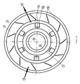
- Fig. 1 a vertically guided axial section through a sewage treatment plant according to the invention and Fig. 2 show a top view, however, with dismantled manipulation unit.
- the treatment plant is formed by concentrically arranged basin, wherein on a base plate 1, an annular outer wall 2 is provided, which limits the treatment plant to the outside.
- annular outer wall 2 is provided, which limits the treatment plant to the outside.
- This annular outer wall 2 defines an activation tank 3 outside, which activation tank 3 is delimited on the inside by a preferably conically upwardly diverging partition 4 of a secondary clarifier 5.
- This partition 4 is preferably made of stainless steel (stainless steel) and provided at the upper end with a clear water tank 6, which extends annularly, ie around the entire partition wall 4, and on the one hand of the conical partition 4 and on the other hand of an approximately zylinderfömig in one certain height on the partition wall 4 attaching wall 7 is delimited by the secondary clarifier 5.
- This cylinder-shaped wall 7 is also formed of stainless steel.
- the clear water tank can also be a different than in Fig. 1 have shown cross-sectional shape - essential is the annular design.
- a sludge collecting container 8 which is delimited from the secondary clarifier 5 by means of an annular wall 9.
- the conical partition 4 results in a very stable self-supporting construction.
- a manipulation unit is provided, which is about an axis of rotation 11, which coincides with the central center axis 12 of the basins 3, 5 and 6, either on a the ponds 3, 5 and 6 spanning bridge 13 or on a the basins 3, 5 and 6 are completely rotatably mounted ceiling covering.
- To rotate the manipulation unit 10 is also a centrally arranged drive 14th
- Fig. 1 how out Fig. 1 can be seen, the wastewater flows through a above the normal waste water level in the aeration tank 3 opening inlet 15 in this.
- the aeration tank 3 is equipped with a pressure aeration device 16 extending near the bottom over its bottom surface.
- the wastewater flows through discharge openings 17, which are provided in the conical dividing wall 4, to the secondary clarifier 5, below the clear water basin 6 attached to the conical dividing wall 4.
- the discharge openings 17 extend from a downwardly extending opening 17 Immersion skirt 18 covered, so that the wastewater or activated sludge that passes through these openings 17 in the secondary clarifier 5, within these diving aprons 18 - these are how out Fig. 2 can be seen distributed over the circumference provided - a degassing finds, which gases back up through the drain holes 17 back into the aeration tank 3.
- the turbid water or activated sludge is lifted from the floor area by means of a mounted on the manipulation unit 10, ie their transversely extending over the pool support 19, and on the one hand via a return sludge conveyor 21 of the sludge conveyor 20 in the aeration tank 3 and on the other hand a surplus sludge conveyor 22 in the centrally disposed sludge collecting 8 passed over.
- the central of the manipulation unit 10 via a Rotary coupling is supplied and is fed from there via compressed air lines 24 to the air pressure openings, is supplied.
- the individual compressed air lines 24 are provided with preferably heatable solenoid valves 25 for controlling the amount of compressed air and thus the flow rate.
- the carrier 19 of the manipulation unit 10 is provided at its opposite end of the mud conveyor 20 with a Wegschlammaufillon 26 having a scum bag 27 to which a movable in level water discharge strip 28 is provided whose level determines the ingress of scum into the scum bag 27.
- This water discharge strip 28 is adapted by means of floating bodies, not shown, to the level 29 of the liquid level of the secondary settling tank 5. This ensures that primarily scum and not too much already clarified water enters the scum bag 27.
- compressed air supply lines 32 are provided, wherein the delivery rate is also adjustable with solenoid valves 25, so that the amount of recirculated or the redirected scum is precisely metered.
- the clarified water now passes through clear water drainage holes 33, which are arranged distributed in the cylindrical partition, which separates the secondary clarifier from the clear water basin, and several times over the circumference, in the gutter-shaped clear water basin 6.
- a plurality of clear water drainage holes 33 prevents drifting of alluvial substances.
- the clear water also passes through a drain 34, which is led from the clear water tank 6 through the aeration tank 3, out of the sewage treatment plant, said drain 34 is equipped with a sifonartig upwardly extending portion 35 for controlling the waste water or clear water level 29.
- a drain opening 36 is provided, from which a sludge discharge line 37 leads away from the sewage treatment plant, for example, leads to a sludge dewatering machine.
- a turbid water outlet 38 is provided in the sludge collecting 8 in the sludge collecting 8. Furthermore project into the mud collection container 8 provided on the manipulation unit 10 Krählstäbe 39, which cause the same a homogenization of the sludge and a better static thickening.
- a particular advantage of the sewage treatment plant according to the invention is the fact that with a manipulation unit 10, all basins 3, 5 and 6 as well as the sludge collection tank 8 in all areas, i. by turning the manipulation unit 10 by 360 °, accessible and workable.
- the entire base area of the secondary clarifier 5 is achieved by means of the sludge conveyor, and it is also the return sludge over the entire circumference of the activated sludge tank 3 introduced into this. This prevents a plug flow in the activation and ensures a vertical flow through the secondary settling tank 5. This also applies to the Wegschlammaufêt 26.
- the wastewater treatment plant according to the invention is particularly suitable for municipal and industrial wastewater treatment plants.
- the activated sludge plant system is characterized by a compact design and functional design of the biological treatment stage.
- the sewage treatment plant according to the invention can be used both for a single-stage plant with simultaneous sludge stabilization and in two-stage plants with anaerobic sludge treatment.
- the levels 29 of the water level in the aeration tank 3, the secondary clarifier 5 and the clear water tank 6 are always balanced due to the hydraulic connection of the tanks 3, 5 and 6. As a result, a homogenization of the sequence is given by a buffer effect at higher feed rates, which adjusts according to the flow characteristic.
- the manipulation unit 10 is controlled by its own control unit or a plant process control system.
- Mud quantities to be delivered can be regulated to that extent, on the one hand on the switch-on of the system and on the other hand on the adjustable by means of solenoid valves compressed air amount of the sludge conveyor.
- the deducted excess sludge is also regulated over the duty cycle of the system. In this case, the amount of sludge to be deducted can be transferred over the whole day in small quantities in the sludge collecting 8. In order to enable the turbid water discharge from the sludge collecting 8 efficiently, a few hours before the deduction of the turbid water, no excess sludge is introduced into the sludge collecting container 8.
Landscapes
- Chemical & Material Sciences (AREA)
- Chemical Kinetics & Catalysis (AREA)
- Life Sciences & Earth Sciences (AREA)
- Engineering & Computer Science (AREA)
- Water Supply & Treatment (AREA)
- Biodiversity & Conservation Biology (AREA)
- Microbiology (AREA)
- Hydrology & Water Resources (AREA)
- Health & Medical Sciences (AREA)
- Environmental & Geological Engineering (AREA)
- Toxicology (AREA)
- Organic Chemistry (AREA)
- Biological Treatment Of Waste Water (AREA)
- Separation Of Suspended Particles By Flocculating Agents (AREA)
- Activated Sludge Processes (AREA)
- Aeration Devices For Treatment Of Activated Polluted Sludge (AREA)
- Water Treatment By Sorption (AREA)
Priority Applications (3)
| Application Number | Priority Date | Filing Date | Title |
|---|---|---|---|
| SI200530464T SI1588987T1 (sl) | 2004-04-14 | 2005-04-14 | Čistilna naprava s koncentrično razporejenimi bazeni |
| AT05450068T ATE405526T1 (de) | 2004-04-14 | 2005-04-14 | Kläranlage mit konzentrisch angeordneten becken |
| PL05450068T PL1588987T3 (pl) | 2004-04-14 | 2005-04-14 | Oczyszczalnia ścieków mająca współśrodkowe zbiorniki |
Applications Claiming Priority (2)
| Application Number | Priority Date | Filing Date | Title |
|---|---|---|---|
| AT6412004 | 2004-04-14 | ||
| AT0064104A AT414124B (de) | 2004-04-14 | 2004-04-14 | Kläranlage |
Publications (2)
| Publication Number | Publication Date |
|---|---|
| EP1588987A1 EP1588987A1 (de) | 2005-10-26 |
| EP1588987B1 true EP1588987B1 (de) | 2008-08-20 |
Family
ID=34943321
Family Applications (1)
| Application Number | Title | Priority Date | Filing Date |
|---|---|---|---|
| EP05450068A Expired - Lifetime EP1588987B1 (de) | 2004-04-14 | 2005-04-14 | Kläranlage mit konzentrisch angeordneten Becken |
Country Status (7)
| Country | Link |
|---|---|
| EP (1) | EP1588987B1 (sr) |
| AT (2) | AT414124B (sr) |
| DE (1) | DE502005005062D1 (sr) |
| HR (1) | HRP20080570T3 (sr) |
| PL (1) | PL1588987T3 (sr) |
| RS (1) | RS50679B (sr) |
| SI (1) | SI1588987T1 (sr) |
Families Citing this family (3)
| Publication number | Priority date | Publication date | Assignee | Title |
|---|---|---|---|---|
| CN107961567A (zh) * | 2017-11-28 | 2018-04-27 | 深圳市万佳晟环保产业有限公司 | 泥浆分离装置 |
| CN116495858B (zh) * | 2023-06-27 | 2023-10-20 | 中铁建工集团有限公司 | 一种高效的污水处理沉淀池 |
| CN118933617B (zh) * | 2024-07-23 | 2025-11-11 | 中国石油天然气集团有限公司 | 钻井泥浆溢流预警监测设备 |
Family Cites Families (6)
| Publication number | Priority date | Publication date | Assignee | Title |
|---|---|---|---|---|
| US3118835A (en) * | 1960-10-27 | 1964-01-21 | Eugene W Butler | Complete oxidation sewage treatment plant |
| US3733263A (en) * | 1971-03-01 | 1973-05-15 | Kimberly Clark Co | Waste treatment system |
| DE2150939A1 (de) * | 1971-10-13 | 1973-04-26 | Karl Hach | Belebungsbecken und dessen verbindung mit dem nachklaerbecken bei klaeranlagen konzentrischen aufbaus, bei denen das nachklaerbecken als rundbecken und das belebungsbecken als ein um das nachklaerbecken gefuehrtes ringbecken ausgebildet ist |
| US3764012A (en) * | 1972-07-24 | 1973-10-09 | B Bohnke | Automatically operable two stage biological compact clearing installation |
| US4197202A (en) * | 1978-07-19 | 1980-04-08 | Przedsiebiorstwo Instalacjiprzemyslowych "Instal" | Biological sewage treatment plant |
| EP1114797A1 (en) * | 2000-01-05 | 2001-07-11 | Sirius B.V. | Device for the purification of waste water. |
-
2004
- 2004-04-14 AT AT0064104A patent/AT414124B/de not_active IP Right Cessation
-
2005
- 2005-04-14 AT AT05450068T patent/ATE405526T1/de not_active IP Right Cessation
- 2005-04-14 PL PL05450068T patent/PL1588987T3/pl unknown
- 2005-04-14 DE DE502005005062T patent/DE502005005062D1/de not_active Expired - Lifetime
- 2005-04-14 EP EP05450068A patent/EP1588987B1/de not_active Expired - Lifetime
- 2005-04-14 SI SI200530464T patent/SI1588987T1/sl unknown
- 2005-04-14 RS RSP-2008/0560A patent/RS50679B/sr unknown
-
2008
- 2008-11-11 HR HR20080570T patent/HRP20080570T3/xx unknown
Also Published As
| Publication number | Publication date |
|---|---|
| RS50679B (sr) | 2010-06-30 |
| ATE405526T1 (de) | 2008-09-15 |
| HRP20080570T3 (en) | 2009-02-28 |
| PL1588987T3 (pl) | 2009-01-30 |
| SI1588987T1 (sl) | 2009-06-30 |
| DE502005005062D1 (de) | 2008-10-02 |
| ATA6412004A (de) | 2005-12-15 |
| EP1588987A1 (de) | 2005-10-26 |
| AT414124B (de) | 2006-09-15 |
Similar Documents
| Publication | Publication Date | Title |
|---|---|---|
| DE1904206A1 (de) | Anlage zur Abwasserreinigung durch Flockung und Belebung | |
| EP1919833B1 (de) | Vorrichtung zur abwasserreinigung | |
| EP1582263B1 (de) | Drucklufthebeanlage für fliessfähige Medien | |
| DE202008003062U1 (de) | Biologische Klärvorrichtung | |
| DE9204960U1 (de) | Vorrichtung zur Entnahme von geklärtem Abwasser aus Rundbecken | |
| EP1588987B1 (de) | Kläranlage mit konzentrisch angeordneten Becken | |
| EP0893413A1 (de) | Verfahren und Vorrichtung zur biologischen Behandlung von Flüssigkeiten, insbesondere zur vollbiologischen Klärung von Abwasser | |
| DE2239041A1 (de) | Reinigungsanlage fuer abwasser | |
| DE20020795U1 (de) | Vorrichtung zum Behandeln von Abwasser | |
| DE102009039316A1 (de) | Abwasserreinigungsanlage und Verfahren zur Abwasserreinigung | |
| DE19939917C1 (de) | Mehrkammerklärgrube | |
| DE4112377C2 (de) | Kompaktreaktor für die aerobe biologische Abwasserreinigung | |
| DE2403334A1 (de) | Klaeranlage | |
| DE2255703A1 (de) | Mechanisch-biologische abwasserreinigungsanlage | |
| EP1094163A2 (de) | Mehrzweckschacht, Kleinkläranlage und Abwasserbehandlungsverfahren | |
| DE4122804A1 (de) | Klaeranlage | |
| EP0535197B1 (de) | Einrichtung zur abtrennung des biologischen schlammes vom gereinigten wasser | |
| EP1138363A2 (de) | Vorrichtung und Verfahren zum Abziehen von gereinigtem Wasser aus einem Behälter bei der biologischen Reinigung von Abwasser | |
| AT391854B (de) | Vorrichtung zur aeroben abwasserreinigung | |
| DE19527970A1 (de) | Kläranlage, insbesondere Bodenfilterkläranlage | |
| AT502184B1 (de) | Einrichtung zur anaeroben biologischen abwasserreinigung | |
| WO1999057068A1 (de) | Vollbiologische kleinkläranlage | |
| DE2144808A1 (de) | Vorrichtung zur biologischen abwasserreinigung nach dem belebtschlammverfahren | |
| DE1658132C3 (de) | Anlage zur Klärung von Abwasser | |
| DE102006005865A1 (de) | Pumpvorrichtung zum Pumpen von Abwasser |
Legal Events
| Date | Code | Title | Description |
|---|---|---|---|
| PUAI | Public reference made under article 153(3) epc to a published international application that has entered the european phase |
Free format text: ORIGINAL CODE: 0009012 |
|
| AK | Designated contracting states |
Kind code of ref document: A1 Designated state(s): AT BE BG CH CY CZ DE DK EE ES FI FR GB GR HU IE IS IT LI LT LU MC NL PL PT RO SE SI SK TR |
|
| AX | Request for extension of the european patent |
Extension state: AL BA HR LV MK YU |
|
| 17P | Request for examination filed |
Effective date: 20060426 |
|
| AKX | Designation fees paid |
Designated state(s): AT BE BG CH CY CZ DE DK EE ES FI FR GB GR HU IE IS IT LI LT LU MC NL PL PT RO SE SI SK TR |
|
| AXX | Extension fees paid |
Extension state: YU Payment date: 20060426 Extension state: AL Payment date: 20060426 Extension state: LV Payment date: 20060426 Extension state: BA Payment date: 20060426 Extension state: MK Payment date: 20060426 Extension state: HR Payment date: 20060426 |
|
| GRAP | Despatch of communication of intention to grant a patent |
Free format text: ORIGINAL CODE: EPIDOSNIGR1 |
|
| GRAS | Grant fee paid |
Free format text: ORIGINAL CODE: EPIDOSNIGR3 |
|
| GRAA | (expected) grant |
Free format text: ORIGINAL CODE: 0009210 |
|
| AK | Designated contracting states |
Kind code of ref document: B1 Designated state(s): AT BE BG CH CY CZ DE DK EE ES FI FR GB GR HU IE IS IT LI LT LU MC NL PL PT RO SE SI SK TR |
|
| AX | Request for extension of the european patent |
Extension state: AL BA HR LV MK YU |
|
| REG | Reference to a national code |
Ref country code: GB Ref legal event code: FG4D Free format text: NOT ENGLISH |
|
| REG | Reference to a national code |
Ref country code: CH Ref legal event code: EP |
|
| REG | Reference to a national code |
Ref country code: IE Ref legal event code: FG4D Free format text: LANGUAGE OF EP DOCUMENT: GERMAN |
|
| REF | Corresponds to: |
Ref document number: 502005005062 Country of ref document: DE Date of ref document: 20081002 Kind code of ref document: P |
|
| REG | Reference to a national code |
Ref country code: HR Ref legal event code: TUEP Ref document number: P20080570 Country of ref document: HR |
|
| REG | Reference to a national code |
Ref country code: RO Ref legal event code: EPE |
|
| REG | Reference to a national code |
Ref country code: GR Ref legal event code: EP Ref document number: 20080403168 Country of ref document: GR |
|
| PG25 | Lapsed in a contracting state [announced via postgrant information from national office to epo] |
Ref country code: NL Free format text: LAPSE BECAUSE OF FAILURE TO SUBMIT A TRANSLATION OF THE DESCRIPTION OR TO PAY THE FEE WITHIN THE PRESCRIBED TIME-LIMIT Effective date: 20080820 Ref country code: LT Free format text: LAPSE BECAUSE OF FAILURE TO SUBMIT A TRANSLATION OF THE DESCRIPTION OR TO PAY THE FEE WITHIN THE PRESCRIBED TIME-LIMIT Effective date: 20080820 Ref country code: IS Free format text: LAPSE BECAUSE OF FAILURE TO SUBMIT A TRANSLATION OF THE DESCRIPTION OR TO PAY THE FEE WITHIN THE PRESCRIBED TIME-LIMIT Effective date: 20081220 |
|
| REG | Reference to a national code |
Ref country code: PL Ref legal event code: T3 |
|
| PG25 | Lapsed in a contracting state [announced via postgrant information from national office to epo] |
Ref country code: FI Free format text: LAPSE BECAUSE OF FAILURE TO SUBMIT A TRANSLATION OF THE DESCRIPTION OR TO PAY THE FEE WITHIN THE PRESCRIBED TIME-LIMIT Effective date: 20080820 Ref country code: ES Free format text: LAPSE BECAUSE OF FAILURE TO SUBMIT A TRANSLATION OF THE DESCRIPTION OR TO PAY THE FEE WITHIN THE PRESCRIBED TIME-LIMIT Effective date: 20081201 |
|
| REG | Reference to a national code |
Ref country code: HR Ref legal event code: T1PR Ref document number: P20080570 Country of ref document: HR |
|
| REG | Reference to a national code |
Ref country code: IE Ref legal event code: FD4D |
|
| PG25 | Lapsed in a contracting state [announced via postgrant information from national office to epo] |
Ref country code: IE Free format text: LAPSE BECAUSE OF FAILURE TO SUBMIT A TRANSLATION OF THE DESCRIPTION OR TO PAY THE FEE WITHIN THE PRESCRIBED TIME-LIMIT Effective date: 20080820 Ref country code: DK Free format text: LAPSE BECAUSE OF FAILURE TO SUBMIT A TRANSLATION OF THE DESCRIPTION OR TO PAY THE FEE WITHIN THE PRESCRIBED TIME-LIMIT Effective date: 20080820 |
|
| REG | Reference to a national code |
Ref country code: HU Ref legal event code: AG4A Ref document number: E004842 Country of ref document: HU |
|
| PG25 | Lapsed in a contracting state [announced via postgrant information from national office to epo] |
Ref country code: PT Free format text: LAPSE BECAUSE OF FAILURE TO SUBMIT A TRANSLATION OF THE DESCRIPTION OR TO PAY THE FEE WITHIN THE PRESCRIBED TIME-LIMIT Effective date: 20090120 |
|
| PLBE | No opposition filed within time limit |
Free format text: ORIGINAL CODE: 0009261 |
|
| STAA | Information on the status of an ep patent application or granted ep patent |
Free format text: STATUS: NO OPPOSITION FILED WITHIN TIME LIMIT |
|
| 26N | No opposition filed |
Effective date: 20090525 |
|
| PG25 | Lapsed in a contracting state [announced via postgrant information from national office to epo] |
Ref country code: EE Free format text: LAPSE BECAUSE OF FAILURE TO SUBMIT A TRANSLATION OF THE DESCRIPTION OR TO PAY THE FEE WITHIN THE PRESCRIBED TIME-LIMIT Effective date: 20080820 |
|
| REG | Reference to a national code |
Ref country code: CH Ref legal event code: PL |
|
| PG25 | Lapsed in a contracting state [announced via postgrant information from national office to epo] |
Ref country code: CH Free format text: LAPSE BECAUSE OF NON-PAYMENT OF DUE FEES Effective date: 20090430 Ref country code: SE Free format text: LAPSE BECAUSE OF FAILURE TO SUBMIT A TRANSLATION OF THE DESCRIPTION OR TO PAY THE FEE WITHIN THE PRESCRIBED TIME-LIMIT Effective date: 20081120 Ref country code: LI Free format text: LAPSE BECAUSE OF NON-PAYMENT OF DUE FEES Effective date: 20090430 |
|
| PGFP | Annual fee paid to national office [announced via postgrant information from national office to epo] |
Ref country code: RO Payment date: 20091029 Year of fee payment: 5 |
|
| PG25 | Lapsed in a contracting state [announced via postgrant information from national office to epo] |
Ref country code: MC Free format text: LAPSE BECAUSE OF NON-PAYMENT OF DUE FEES Effective date: 20090430 |
|
| PGFP | Annual fee paid to national office [announced via postgrant information from national office to epo] |
Ref country code: HU Payment date: 20100712 Year of fee payment: 6 |
|
| PGFP | Annual fee paid to national office [announced via postgrant information from national office to epo] |
Ref country code: AT Payment date: 20100809 Year of fee payment: 6 |
|
| PGFP | Annual fee paid to national office [announced via postgrant information from national office to epo] |
Ref country code: BG Payment date: 20101101 Year of fee payment: 6 |
|
| PG25 | Lapsed in a contracting state [announced via postgrant information from national office to epo] |
Ref country code: IT Free format text: LAPSE BECAUSE OF NON-PAYMENT OF DUE FEES Effective date: 20090414 |
|
| PG25 | Lapsed in a contracting state [announced via postgrant information from national office to epo] |
Ref country code: LU Free format text: LAPSE BECAUSE OF NON-PAYMENT OF DUE FEES Effective date: 20090414 |
|
| PGRI | Patent reinstated in contracting state [announced from national office to epo] |
Ref country code: IT Effective date: 20110616 |
|
| PGFP | Annual fee paid to national office [announced via postgrant information from national office to epo] |
Ref country code: PL Payment date: 20110414 Year of fee payment: 7 |
|
| PG25 | Lapsed in a contracting state [announced via postgrant information from national office to epo] |
Ref country code: CY Free format text: LAPSE BECAUSE OF FAILURE TO SUBMIT A TRANSLATION OF THE DESCRIPTION OR TO PAY THE FEE WITHIN THE PRESCRIBED TIME-LIMIT Effective date: 20080820 |
|
| PG25 | Lapsed in a contracting state [announced via postgrant information from national office to epo] |
Ref country code: RO Free format text: LAPSE BECAUSE OF NON-PAYMENT OF DUE FEES Effective date: 20100414 |
|
| REG | Reference to a national code |
Ref country code: AT Ref legal event code: MM01 Ref document number: 405526 Country of ref document: AT Kind code of ref document: T Effective date: 20110414 |
|
| PG25 | Lapsed in a contracting state [announced via postgrant information from national office to epo] |
Ref country code: HU Free format text: LAPSE BECAUSE OF NON-PAYMENT OF DUE FEES Effective date: 20110415 |
|
| PG25 | Lapsed in a contracting state [announced via postgrant information from national office to epo] |
Ref country code: AT Free format text: LAPSE BECAUSE OF NON-PAYMENT OF DUE FEES Effective date: 20110414 |
|
| PGFP | Annual fee paid to national office [announced via postgrant information from national office to epo] |
Ref country code: BE Payment date: 20120418 Year of fee payment: 8 Ref country code: TR Payment date: 20120425 Year of fee payment: 8 |
|
| PGFP | Annual fee paid to national office [announced via postgrant information from national office to epo] |
Ref country code: FR Payment date: 20120507 Year of fee payment: 8 Ref country code: GB Payment date: 20120419 Year of fee payment: 8 |
|
| PGFP | Annual fee paid to national office [announced via postgrant information from national office to epo] |
Ref country code: IT Payment date: 20120418 Year of fee payment: 8 |
|
| REG | Reference to a national code |
Ref country code: HR Ref legal event code: ODRP Ref document number: P20080570 Country of ref document: HR Payment date: 20130320 Year of fee payment: 9 |
|
| PGFP | Annual fee paid to national office [announced via postgrant information from national office to epo] |
Ref country code: CZ Payment date: 20130321 Year of fee payment: 9 |
|
| PGFP | Annual fee paid to national office [announced via postgrant information from national office to epo] |
Ref country code: GR Payment date: 20130328 Year of fee payment: 9 Ref country code: SK Payment date: 20130321 Year of fee payment: 9 |
|
| PG25 | Lapsed in a contracting state [announced via postgrant information from national office to epo] |
Ref country code: BG Free format text: LAPSE BECAUSE OF NON-PAYMENT OF DUE FEES Effective date: 20111231 |
|
| PGFP | Annual fee paid to national office [announced via postgrant information from national office to epo] |
Ref country code: DE Payment date: 20130430 Year of fee payment: 9 |
|
| REG | Reference to a national code |
Ref country code: PL Ref legal event code: LAPE |
|
| PG25 | Lapsed in a contracting state [announced via postgrant information from national office to epo] |
Ref country code: PL Free format text: LAPSE BECAUSE OF NON-PAYMENT OF DUE FEES Effective date: 20120414 |
|
| PGFP | Annual fee paid to national office [announced via postgrant information from national office to epo] |
Ref country code: SI Payment date: 20130320 Year of fee payment: 9 |
|
| BERE | Be: lapsed |
Owner name: WADL, SIEGFRIED Effective date: 20130430 |
|
| GBPC | Gb: european patent ceased through non-payment of renewal fee |
Effective date: 20130414 |
|
| PG25 | Lapsed in a contracting state [announced via postgrant information from national office to epo] |
Ref country code: GB Free format text: LAPSE BECAUSE OF NON-PAYMENT OF DUE FEES Effective date: 20130414 Ref country code: BE Free format text: LAPSE BECAUSE OF NON-PAYMENT OF DUE FEES Effective date: 20130430 |
|
| REG | Reference to a national code |
Ref country code: FR Ref legal event code: ST Effective date: 20131231 |
|
| PG25 | Lapsed in a contracting state [announced via postgrant information from national office to epo] |
Ref country code: FR Free format text: LAPSE BECAUSE OF NON-PAYMENT OF DUE FEES Effective date: 20130430 Ref country code: IT Free format text: LAPSE BECAUSE OF NON-PAYMENT OF DUE FEES Effective date: 20130414 |
|
| REG | Reference to a national code |
Ref country code: DE Ref legal event code: R119 Ref document number: 502005005062 Country of ref document: DE |
|
| REG | Reference to a national code |
Ref country code: HR Ref legal event code: PBON Ref document number: P20080570 Country of ref document: HR Effective date: 20140414 |
|
| REG | Reference to a national code |
Ref country code: SK Ref legal event code: MM4A Ref document number: E 4491 Country of ref document: SK Effective date: 20140414 |
|
| REG | Reference to a national code |
Ref country code: GR Ref legal event code: ML Ref document number: 20080403168 Country of ref document: GR Effective date: 20141104 |
|
| REG | Reference to a national code |
Ref country code: DE Ref legal event code: R119 Ref document number: 502005005062 Country of ref document: DE Effective date: 20141101 |
|
| PG25 | Lapsed in a contracting state [announced via postgrant information from national office to epo] |
Ref country code: CZ Free format text: LAPSE BECAUSE OF NON-PAYMENT OF DUE FEES Effective date: 20140414 Ref country code: SK Free format text: LAPSE BECAUSE OF NON-PAYMENT OF DUE FEES Effective date: 20140414 Ref country code: GR Free format text: LAPSE BECAUSE OF NON-PAYMENT OF DUE FEES Effective date: 20141104 Ref country code: DE Free format text: LAPSE BECAUSE OF NON-PAYMENT OF DUE FEES Effective date: 20141101 |
|
| REG | Reference to a national code |
Ref country code: SI Ref legal event code: KO00 Effective date: 20141209 |
|
| PG25 | Lapsed in a contracting state [announced via postgrant information from national office to epo] |
Ref country code: SI Free format text: LAPSE BECAUSE OF NON-PAYMENT OF DUE FEES Effective date: 20140415 |
|
| PG25 | Lapsed in a contracting state [announced via postgrant information from national office to epo] |
Ref country code: TR Free format text: LAPSE BECAUSE OF NON-PAYMENT OF DUE FEES Effective date: 20140414 |